EP2474912A1 - Datenlieferungsvorrichtung, -system und -verfahren sowie computerprogramm dafür - Google Patents
Datenlieferungsvorrichtung, -system und -verfahren sowie computerprogramm dafür Download PDFInfo
- Publication number
- EP2474912A1 EP2474912A1 EP10813599A EP10813599A EP2474912A1 EP 2474912 A1 EP2474912 A1 EP 2474912A1 EP 10813599 A EP10813599 A EP 10813599A EP 10813599 A EP10813599 A EP 10813599A EP 2474912 A1 EP2474912 A1 EP 2474912A1
- Authority
- EP
- European Patent Office
- Prior art keywords
- data
- supply
- probability
- supply apparatus
- stored
- Prior art date
- Legal status (The legal status is an assumption and is not a legal conclusion. Google has not performed a legal analysis and makes no representation as to the accuracy of the status listed.)
- Ceased
Links
Images



Classifications
-
- H—ELECTRICITY
- H04—ELECTRIC COMMUNICATION TECHNIQUE
- H04N—PICTORIAL COMMUNICATION, e.g. TELEVISION
- H04N21/00—Selective content distribution, e.g. interactive television or video on demand [VOD]
- H04N21/20—Servers specifically adapted for the distribution of content, e.g. VOD servers; Operations thereof
- H04N21/21—Server components or server architectures
- H04N21/218—Source of audio or video content, e.g. local disk arrays
- H04N21/21815—Source of audio or video content, e.g. local disk arrays comprising local storage units
Definitions
- the present invention relates to a data supply apparatus, a data supply system, and a data supply method, and a computer program, in particular, to those preferably applied to a widely distributed system, by which when supplying data to data supply destinations which are hierarchically connected on a logical network, a data supply instruction can be simplified, an automatic data supply which meets a demand according to increase or decrease in the data supply destinations can be performed, and characteristics such as geographical or temporal data use tendency can be reflected in supply results.
- a data supply apparatus a data supply system, and a data supply method, and a computer program, in particular, to those preferably applied to a widely distributed system, by which when supplying data to data supply destinations which are hierarchically connected on a logical network, a data supply instruction can be simplified, an automatic data supply which meets a demand according to increase or decrease in the data supply destinations can be performed, and characteristics such as geographical or temporal data use tendency can be reflected in supply results.
- Fig. 11 is a diagram showing an example of an existing data supply system preferably applied to a widely distributed system.
- the data supply system (CDN: Contents Delivery Network) of Fig. 11 has a hierarchical logical tree structure corresponding to the number of users or a geographical range covered by the system, and performs appropriate content supply in response to each audience request from users. Accordingly, it is possible to implement high speed responsibility, efficient network usage, and the like.
- the above “supply” means a process of transferring a content to another apparatus, and making the transferred content into a storage device of the relevant apparatus. In the following descriptions, the term “supply” is used to have such a meaning.
- each DC 11 has a three-tier (hierarchical) structure constituting of DCs (Data Centers) from a DC arranged in a metropolitan area to DCs arranged in middle-ranking provincial cities.
- DCs Data Centers
- the manner of forming a hierarchy and the number of tiers are not limited to those in the example.
- the size of each DC has a general relationship "Tier 1 > Tier 2 > Tier 3", that is, the higher the tier, the larger the size of each DC belonging to the relevant tier.
- the capacity for contents storable in each DC has a similar relationship.
- each DC in Tier 3 stores part of contents stored in a DC belonging to Tier 1 or Tier 2.
- content A is provided from the metropolitan DC to the high-ranking provincial city DC1 in response to each access from the users who are connected to the high-ranking provincial city DC1. Additionally, in response to each access from the users who are connected to the middle-ranking provincial city DC1, content A is provided from the metropolitan DC to the relevant high-ranking provincial city DC1, and is further provided from the high-ranking provincial city DC1 to the relevant middle-ranking provincial city DC1.
- content A has been supplied to the high-ranking provincial city DC1 which now stores content A
- content A can be directly supplied to a user, who is connected to the high-ranking provincial city DC1 and accesses content A, without receiving the relevant content from another DC.
- content A is provided from the high-ranking provincial city DC1 to the middle-ranking provincial city DC1. That is, in comparison with a case in that only the metropolitan DC stores content A, a higher level of network usage efficiency can be obtained.
- the lower the tier the smaller the size of each DC belonging to the relevant tier, it is not preferable to supply all contents to all DCs.
- Fig. 12 is a diagram showing a known method for clearly designating DCs to which each content should be supplied.
- DCs to which each content should be supplied may be clearly designated.
- this method cannot solve the following problems.
- Patent Document 1 discloses a system configured by adding a distribution destination information DB to an existing content distribution system. In the configured system, relevant contents are distributed to terminals registered in the distribution destination information DB, based on a prepared distribution schedule and distribution conditions.
- Patent Document 2 discloses a technique for a data supply system, in which dynamic and optimum content resupply to an edge server, from which a user terminal device directly reads a content, is performed, based on user's viewing records, thereby maintaining desired service quality and implementing efficient system operation.
- the conventional content distribution systems shown in the BACKGROUND ART has the following problems, as described above.
- the first problem since it is necessary to perform a computation to determine for each supply spot (supplier) whether or not content supply is performed, and also necessary to clearly designate for each supply destination, the relevant computation for determining the content supply destination requires a considerable amount of cost. Although the determination of the content supply destination may be manually performed based on personal experience, such determination requires a complex manual designation of the content supply destination.
- the second problem since it is necessary to clearly designate the content supply destination, the increase or decrease of the content supply destinations cannot be easily handled.
- the third problem since the content supply information is statically designated, a dynamic variation in demand for contents cannot be handled, so that appropriate data supply suited for such demand cannot be performed.
- the fourth problem since information about use tendency of each content cannot be considered in the relevant content supply designation method, the supply destination must be examined or controlled for each content.
- a user's viewing record is stored for each content, and stored information is analyzed so as to determine resupply of the relevant data.
- Such a system causes other problems about the scalability for viewing record storage and management with respect to the number of contents, and the scalability of increases in the amount of computation performed in the analysis for information about the number of contents.
- the term "content" which is generally used so as to indicate video data or voice data, is used to indicate an object handled in the relevant system.
- the present invention can be applied, not only to contents, but also to general data.
- an object of the present invention is to provide a data supply apparatus, a data supply system, and a data supply method, and a computer program, which are applied to a widely distributed system and can reduce the cost required for the computation to determine each data supply destination.
- Another object of the present invention is to provide a data supply apparatus, a data supply system, and a data supply method, and a computer program, which are applied to a widely distributed system and can easily handle the increase or decrease of the data supply destinations.
- Another object of the present invention is to provide a data supply apparatus, a data supply system, and a data supply method, and a computer program, which are applied to a widely distributed system and can implement automatic data supply in response to a variation in demand for relevant data.
- Another object of the present invention is to provide a data supply apparatus, a data supply system, and a data supply method, and a computer program, which are applied to a widely distributed system and can implement performance (for responsibility, network usage efficiency, and the like) of a certain desired level even without examining or controlling the data supplier for each data.
- the present invention was made to solve the above problems, and provides a data supply apparatus comprising:
- the present invention also provides a data supply system which includes the above data supply apparatus as a constituent of the system.
- the present invention also provides a data supply method comprising:
- the present invention also provides a computer program for controlling a data supply apparatus, the program comprising:
- the data supply apparatus of the present invention when receiving data from another data supply apparatus, whether or not the received data is to be stored in a storage device is determined based on a predetermined supply probability. Therefore, it is unnecessary to set, for each data, whether or not the data can be stored, and the relevant advisability is determined by a simple computation, thereby reducing the computation cost required for data provision or designation of a destination in which data is stored. Additionally, in the data supply system of the present invention, when a supply probability is assigned to each tier (for the data supply apparatuses) in advance, it is unnecessary to assign a supply probability to each data supply apparatus, thereby easily handling the increase or decrease of content supply destinations.
- the present invention it is determined, for each data access, whether or not the data can be stored in a data supply apparatus based on a relevant supply probability. Therefore, it is frequently determined that data which has been frequently accessed is to be stored, so that the higher the access frequency of data, the higher the probability that the data is stored in the data supply apparatus. Accordingly, it is possible to perform appropriate data supply in response to a demand for contents.
- the data supply apparatus of the present invention is preferably applied to widely distributed systems, and provides a logical connection relationship which employs a tree hierarchy.
- the probability of data supply to data supply apparatuses in each tier is contained in each content (or data) itself, each data supply apparatus, or a supply probability providing apparatus.
- each data supply apparatus may have a data storage determination unit and a data storage unit. When data is transferred, the probability of supplying the data is determined in accordance with each tier of the system, and the data is stored in the data storage unit of each present apparatus based on the supply probability.
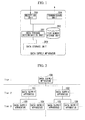
- Fig. 1 is a block diagram showing the general structure of a data supply apparatus as the first embodiment of the present invention.
- Fig. 2 shows an example of a data supply system in which data supply apparatuses for the first embodiment are arranged.
- the data supply apparatus shown in Fig. 1 can be used to configure a widely distributed data supply apparatus as shown in Fig. 2 , and has a data storage unit 200 (e.g., memory or disk) functioning as a storage and primary structural elements which are a data storage determination unit 201 that performs a data storage determination, a tier number storage unit 202 that stores tier number data which is used in the data storage determination, a reception unit 203 that performs data reception, and a transmission unit 204 that performs data transmission.
- a data storage unit 200 e.g., memory or disk
- reference numerals 100, 101, 102, ..., 106, ... each indicate a data supply apparatus belonging to the present embodiment (below, each data supply apparatus in Fig. 2 has structural elements to which reference numerals identical to those in the data supply apparatus 100 of Fig. 1 are applied).
- the data storage unit 200 may be an independent external storage device (such a structure is employed in a specific example explained later).
- the data supply apparatuses in the present embodiment are arranged to form a logical tree (including data supply apparatuses 100 to 106) having a hierarchical structure on such a widely distributed network.
- the relevant hierarchical structure employs numbering, for example, Tier 1, Tier 2, Tier 3, ... as tier numbers assigned starting from the highest tier of the tree, based on natural numbers. Essentially, if each tier can be identified, the numbering method therefor is not limited to the above method based on natural numbers.
- the above-described tier number storage unit 202 stores such hierarchical number data.
- the tree shown in Fig. 2 has two branches, the number of branches (children) are not limited to 2. Furthermore, if hierarchical numbering is possible, a graph structure which can apply a plurality of parents to a child may be employed instead of a tree structure.
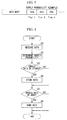
- Fig. 3 is a diagram showing a data structure which indicates data supply probability corresponding to each tier.
- the present apparatus determiners whether or not the received data is stored in the present apparatus based on supply probability information (see Fig. 3 ) appended to the supplied data.
- the supply probability is a probability used when the apparatus which received the relevant data determines whether or not the data should be stored in the present apparatus.
- the supply probability information shown in Fig. 3 may be predetermined in correspondence to each tier on the logical network (detailed explanation therefor will be provided later).
- each data is stored in a data supply apparatus which has frequently accessed the data or a data supply apparatus which is present on a transfer route for the data, with a relatively high probability.
- the probability that data, which has low importance or has not been frequently accessed, is stored in each relevant data supply apparatus is low.
- the supply probability information may be stored in a front part (e.g., header) of data, or in a middle part thereof.
- the supply probability information may be stored separately from the data body, that is, as file management metadata. That is, the supply probability information may be stored in a manner such that the relationship between the relevant information and the corresponding data is clearly indicated.
- a data supply apparatus now requires data which is not stored in the present apparatus (e.g., when receiving a data provision request for the relevant data from a user terminal connected to the present apparatus), and will receive the relevant data from another data supply apparatus.
- a specific example will be shown, in which data is transferred from the data supply apparatus 102 to the data supply apparatus 105 in Fig. 2 .
- the data supply apparatus 102 retrieves the relevant data from the data storage unit 200 (see Fig. 1 ), and sends it to the data supply apparatus 105 via the transmission unit 204.
- the supply probability information (see Fig. 3 ) has been appended to the data stored in the 200.
- the supply probability information can be appended to the data via the data storage determination unit 201 by means of user's operation of an input device (not shown).
- the reception unit 203 of the data supply apparatus 105 receives the transmitted data, and the data storage determination unit 201 of the data supply apparatus 105 determines whether or not the data will be stored into the data storage unit 200 based on the supply probability information (see Fig. 3 ) appended to the data and the tier number (here, "Tier 3") of the present apparatus, which is stored in the tier number storage unit 202.
- the determination of whether or not the data will be stored may be performed as follows.
- the data storage determination unit 201 uses the supply probability information so as to retrieve the supply probability associated with the tier number of the present apparatus, that is, retrieves a supply probability of 60% associated with Tier 3.
- the data storage determination unit 201 then generates random numbers from 1 to 100, and compares each generated random number with the supply probability. If the generated random number is smaller than or equal to the supply probability, it is determined that the relevant data is to be stored in the data storage unit 200. If the generated random number exceeds the supply probability, it is determined that the relevant data is not to be stored in the data storage unit 200.
- the method of data storage determination is not limited above. For example, if the supply probability can be set up to the first decimal place, random numbers from 1 to 1000 may be generated, and the relevant determination may be performed by comparing each generated random number with a value ten times as high as the value of the supply probability.
- the data storage determination unit 201 stores the data into the data storage unit 200.
- the data storage determination unit 201 performs nothing. After that, as the need arises, the data supply apparatus 105 updates the supply probability appended to the relevant data, and transfers the data to an external apparatus via the transmission unit 204.
- Fig. 4 is a flowchart showing an operation of the data supply apparatus in the first embodiment, performed when receiving data. Below, the relevant operation of the data supply apparatus in the first embodiment will be explained by using the flowchart of Fig. 4 while referring to Figs. 1 to 3 . In the following explanation, although reference numeral 100 is conveniently assigned to the target data supply apparatus for the explanation, the other data supply apparatuses each perform similar operation.
- the supply probability is used as a parameter for making the data receiving side determine whether or not the transmitted data should be stored in a storage unit on the receiving side. That is, a data supply apparatus on the data sending side (i) predetermines the supply probability based on the degree of importance for target data, which is associated with the tier (i.e., tier number in the present embodiment) to which a data supply apparatus as the destination of the data belongs on a logical network, and (ii) appends the determined supply probability to the body of the data in advance on the sending side. Accordingly, designation of important data which should be stored onto the receiving side, can be easily performed on the sending side with low cost.
- whether or not the transmitted data should be stored onto the receiving side is designated using a probability based on, not each data supply apparatus as the destination, but the tier to which the data supply apparatus as the destination belongs on a logical network. Therefore, as long as no increase in the number of the tiers occurs, an increase or decrease in the number of data supply destinations can be easily handled.
- the supply probability is used in the data supply designation of the present embodiment, the followings are possible when determining the necessity of data transfer to another data supply apparatus (that is, determining whether or not the relevant data is to be supplied to another data supply apparatus).
- the present embodiment can prevent inappropriate data storage onto the receiving side by appending a relatively low supply probability to the body of data which has relatively low importance or low anticipated frequency for future access.
- a filtering function can also be anticipated as a secondary effect. The reason for the above anticipation follows. If no data supply system based on the present embodiment is used, then each supplied data is stored into the data storage unit 200 for the present even when the data has low importance or low anticipated frequency for future access.
- allocation control based on the URL algorithm may be executed depending on the used amount of the data storage unit 200, which may exclude data, which expectedly has a higher degree of importance or a higher frequency for future access in comparison with the newly stored data, from the relevant memory.
- using a data supply system based on the present embodiment can reduce a probability that data having low importance is stored, and thus the data supply system can function as a filter for the allocation control based on the URL algorithm so as to prevent inappropriate data storage.
- Fig. 5 is a block diagram showing the general structure of a data supply apparatus as the second embodiment of the present invention.
- the tier number storage unit 202 of the data supply apparatus in the first embodiment is replaced with a supply probability storage unit 302.
- the other structural elements are identical to those of the data supply apparatus in the first embodiment.
- an example of the data supply system in which the data supply apparatuses of the present embodiment are arranged is similar to that shown in Fig. 2 .
- the supply probability storage unit 302 a supply probability assigned to the tier to which the present apparatus belongs or supply probabilities assigned to all tiers are stored in advance.
- Each supply probability stored in the supply probability storage unit 302 is not appended to the data body, but stored in the supply probability storage unit 302 (i.e., in the data supply apparatus) as described above.
- information appended to the data body is not supply probability information which indicates a supply probability for each tier number, but scaling factor information that indicates each scaring factor (applicable to all tiers).
- the above scaling factor is a value used for controlling the supply probability for each data (such as a content). For example, when magnification is designated as the scaling factor, the supply probability for the data (such as a content) can be determined by multiplying the magnification by the supply probability stored in the relevant data supply apparatus.
- the scaling factor information may be added in front of data or in the middle of the data, or may be added as separate data (i.e., as file management metadata) from the data body.
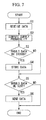
- Fig. 7 is a flowchart showing an operation of the data supply apparatus in the second embodiment, performed when receiving data.
- the relevant operation of the data supply apparatus in the second embodiment will be explained by using the flowchart of Fig. 7 while referring to Figs. 5 and 6 .
- reference numeral 100 is conveniently assigned to the target data supply apparatus for the explanation, the other data supply apparatuses each perform similar operations.
- distinctive features in comparison with the operation of the data supply apparatus in the previously described first embodiment are mainly shown, where reference numerals assigned to each step and sentences in each block are basically identical to those in the flowchart of Fig. 4 , where a part of the sentences is modified.
- step S1 data transferred from another data supply apparatus is received by the reception unit 203 of the data supply apparatus shown in Fig. 5 (see step S1).
- the data supply probability for the relevant data is computed using the supply probability, which is assigned to the present apparatus and stored in the supply probability storage unit 302, and the scaling factor (see Fig. 6 ) appended to the data transferred from said other data supply apparatus (see step S2).
- the data supply probability for the relevant data is computed by multiplying the supply probability assigned to the present apparatus by the scaling factor. Since the operation in the steps from S3 is identical to the operation (shown in the flowchart of Fig. 4 ) of the data supply apparatus in the first embodiment, explanations thereof are omitted here.
- the supply probability can be set, not for each data, but for each tier, or (one supply probability) for all tiers. Therefore, in addition to the effects obtained by the data supply apparatus of the first embodiment of the present invention, setting of the supply probability for each data can be omitted, thereby reducing the storage capacity required for such setting of the supply probability applied to each data body.
- Fig. 8 is a block diagram showing the general structure of a data supply apparatus as the third embodiment of the present invention.
- a supply probability storage unit 401 corresponds to the supply probability storage unit 302 of the data supply apparatus (see Fig. 5 ) in the second embodiment of the present invention, is provided, not within the data supply apparatus, but in a supply probability providing apparatus 400 provided outside the data supply apparatus, where a supply probability obtaining unit 402 is provided in the data supply apparatus, and is positioned between the supply probability storage unit 401 and the data storage determination unit 201.
- the other structural elements are identical to those of the data supply apparatus in the second embodiment of the present invention.
- an example of the data supply system in which the data supply apparatuses of the present embodiment are arranged is similar to that shown in Fig. 2 .
- FIG. 9 is a flowchart showing an operation of the data supply apparatus in the third embodiment, performed when receiving data. Below, the relevant operation of the data supply apparatus in the third embodiment will be explained by using the flowchart of Fig. 9 while referring to Figs. 8 and 6 . In the following explanation, although reference numeral 100 is conveniently assigned to the target data supply apparatus for the explanation, the other data supply apparatuses each perform similar operations.
- step S1 data transferred from another data supply apparatus is received by the reception unit 203 of the data supply apparatus (see Fig. 8 ) (see step S1).
- the supply probability obtaining unit 402 obtains a supply probability for the present apparatus from the supply probability storage unit 401 in the supply probability providing apparatus 400 (see step S2).
- the supply probability obtaining unit 402 then computes the data supply probability for the relevant data by using the obtained supply probability (assigned to the present apparatus) and the scaling factor (see Fig. 6 ) appended to the data (see step S21). Since the operation in the steps from S3 is identical to the operation (shown in the flowchart of Fig. 7 ) of the data supply apparatus in the second embodiment, explanations thereof are omitted here.
- the supply probability providing apparatus 400 which operates outside the data supply apparatus (see Fig. 8 ) and has the supply probability storage unit 401, is provided, and the relevant supply probability is stored in the supply probability storage unit 401 in advance, and is provided from this storage unit. Therefore, it is possible to easily change the data supply probability when the system is operated.
- Fig. 10 shows the system configuration of a cluster distributed file system as an example structure of a network system which includes the data supply apparatus of the present invention.
- the distributed file system of Fig. 10 consists of a DC (data center) 700 (on the server side) connected to an end user 500 and a DC (data center) 800 (on the client side) connected to an end user 600.
- the DC 700 and the DC 800 are connected via a communication line.
- the DC 700 has a data supply apparatus 710 (corresponding to the data supply apparatus in the third embodiment of the present invention) and a file system (on the server side) which includes clients 720 and 730 and file servers 740 to 760.
- the DC 800 has a data supply apparatus 810 (corresponding to the data supply apparatus in the third embodiment of the present invention) and a file system (on the client side) which includes clients 820 and 830 and file servers 840 to 860.
- the DCs 700 and 800 correspond to each DC shown in Fig. 11 .
- the above-described file system on the server side or the file system on the client side each correspond to the data storage unit 200 (see Fig. 8 ).
- the following operation is generally performed when the end user 600 requests the DC 800 to supply data, and the data is not stored in the file system (on the client side) of the DC 800 but is stored in the file server 740 of the DC 700.
- At least part of the operation performed by the structural elements in the data supply apparatus of the present invention is executed by means of computer control.
- a program for making a computer execute the above operation based on the procedure shown in the flowcharts of Figs. 4 , 7 , and 9 may be distributed by storing the program in a computer-readable storage medium such as a semiconductor memory, a CD-ROM, a magnetic tape, or the like.
- the computer which may be a microcomputer, a personal computer, a general purpose computer, or the like, can retrieve the above program from the above-described storage medium so as to execute the program.
- the data supply apparatus in accordance with the present invention can be used in a widely distributed data supply system in a CDN (Contents Delivery Network) or the like, which can be applied to data (e.g., contents) supply or data caching.
- CDN Contents Delivery Network
- the present invention is preferably used when configuring a data supply apparatus and a data supply system suitable for a widely distributed system, by which when supplying data to a destination which is hierarchically connected on a logical network, data supply designation can be simplified, automatic data supply can be performed in response to a demand corresponding to an increase or decrease in the data supply destinations, geographical or temporal data use tendency can be reflected in supply results.
Landscapes
- Engineering & Computer Science (AREA)
- Databases & Information Systems (AREA)
- Multimedia (AREA)
- Signal Processing (AREA)
- Information Transfer Between Computers (AREA)
- Information Retrieval, Db Structures And Fs Structures Therefor (AREA)
- Two-Way Televisions, Distribution Of Moving Picture Or The Like (AREA)
Applications Claiming Priority (2)
| Application Number | Priority Date | Filing Date | Title |
|---|---|---|---|
| JP2009202576 | 2009-09-02 | ||
| PCT/JP2010/063395 WO2011027648A1 (ja) | 2009-09-02 | 2010-08-06 | データ供給装置、システム、及び方法、及びコンピュータプログラム |
Publications (2)
| Publication Number | Publication Date |
|---|---|
| EP2474912A1 true EP2474912A1 (de) | 2012-07-11 |
| EP2474912A4 EP2474912A4 (de) | 2013-03-27 |
Family
ID=43649195
Family Applications (1)
| Application Number | Title | Priority Date | Filing Date |
|---|---|---|---|
| EP10813599A Ceased EP2474912A4 (de) | 2009-09-02 | 2010-08-06 | Datenlieferungsvorrichtung, -system und -verfahren sowie computerprogramm dafür |
Country Status (4)
| Country | Link |
|---|---|
| US (1) | US8903977B2 (de) |
| EP (1) | EP2474912A4 (de) |
| JP (1) | JP5790501B2 (de) |
| WO (1) | WO2011027648A1 (de) |
Family Cites Families (14)
| Publication number | Priority date | Publication date | Assignee | Title |
|---|---|---|---|---|
| US6292828B1 (en) * | 1994-02-23 | 2001-09-18 | David L. Williams | Trans-modal animated information processing with selective engagement |
| US6067565A (en) * | 1998-01-15 | 2000-05-23 | Microsoft Corporation | Technique for prefetching a web page of potential future interest in lieu of continuing a current information download |
| US6182133B1 (en) * | 1998-02-06 | 2001-01-30 | Microsoft Corporation | Method and apparatus for display of information prefetching and cache status having variable visual indication based on a period of time since prefetching |
| US7085843B2 (en) | 2000-07-13 | 2006-08-01 | Lucent Technologies Inc. | Method and system for data layout and replacement in distributed streaming caches on a network |
| JP2004005309A (ja) | 2002-06-03 | 2004-01-08 | Matsushita Electric Ind Co Ltd | コンテンツ配信システムおよびそれに関する方法または記録媒体またはプログラム |
| JP2004246632A (ja) * | 2003-02-14 | 2004-09-02 | Hitachi Ltd | データ分配サーバ、プログラム及びネットワークシステム |
| JP2005070987A (ja) * | 2003-08-22 | 2005-03-17 | Nippon Telegr & Teleph Corp <Ntt> | ファイル共有システムで用いられるノード、ファイル共有システムで用いられるファイル保存方法及びファイル保存プログラム。 |
| US7627617B2 (en) * | 2004-02-11 | 2009-12-01 | Storage Technology Corporation | Clustered hierarchical file services |
| JP2006050479A (ja) * | 2004-08-09 | 2006-02-16 | Ricoh Co Ltd | コンテンツ配信システム、コンテンツ配信サーバ、コンテンツ配信方法、プログラムおよび記録媒体 |
| JP4586203B2 (ja) * | 2004-12-01 | 2010-11-24 | ブラザー工業株式会社 | データ共有システム、及び複製コンテンツデータ保存制御装置等 |
| US7644150B1 (en) * | 2007-08-22 | 2010-01-05 | Narus, Inc. | System and method for network traffic management |
| JP2009202576A (ja) | 2008-01-30 | 2009-09-10 | Ricoh Co Ltd | 画像形成装置、および画像形成装置の画像形成方法 |
| US8051205B2 (en) * | 2008-10-13 | 2011-11-01 | Applied Micro Circuits Corporation | Peer-to-peer distributed storage |
| US8942493B2 (en) * | 2009-11-02 | 2015-01-27 | Panasonic Intellectual Property Corporation Of America | Image coding method, image decoding method, image coding apparatus, and image decoding apparatus |
-
2010
- 2010-08-06 EP EP10813599A patent/EP2474912A4/de not_active Ceased
- 2010-08-06 WO PCT/JP2010/063395 patent/WO2011027648A1/ja not_active Ceased
- 2010-08-06 US US13/392,079 patent/US8903977B2/en active Active
- 2010-08-06 JP JP2011529860A patent/JP5790501B2/ja active Active
Also Published As
| Publication number | Publication date |
|---|---|
| JP5790501B2 (ja) | 2015-10-07 |
| US20120158939A1 (en) | 2012-06-21 |
| WO2011027648A1 (ja) | 2011-03-10 |
| EP2474912A4 (de) | 2013-03-27 |
| JPWO2011027648A1 (ja) | 2013-02-04 |
| US8903977B2 (en) | 2014-12-02 |
Similar Documents
| Publication | Publication Date | Title |
|---|---|---|
| US8086634B2 (en) | Method and apparatus for improving file access performance of distributed storage system | |
| US6401121B1 (en) | File server load distribution system and method | |
| US7234032B2 (en) | Computerized system, method and program product for managing an enterprise storage system | |
| US7580971B1 (en) | Method and apparatus for efficient SQL processing in an n-tier architecture | |
| EP2227016A1 (de) | Inhaltspufferungs- und abfrageverfahren sowie punkt-zu-punkt-medienübertragungssystem | |
| US20120215741A1 (en) | LDAP Replication Priority Queuing Mechanism | |
| EP1430691B1 (de) | Hierarchische cachespeicherung in telekommunikationsnetzen | |
| US20120173486A1 (en) | System and method for dynamically selecting storage locations of replicas in cloud storage system | |
| JP2013525931A (ja) | コンテンツ配信に利用される動的バインド | |
| JP2005004676A (ja) | 適応型分散処理システム | |
| CN102143237A (zh) | 一种基于网格的互联网内容分发方法和系统 | |
| US10296941B2 (en) | System and method for optimizing content distribution | |
| JP2005031987A (ja) | コンテンツ配信システムにおけるコンテンツ配置管理システム及びコンテンツ配置管理プログラム | |
| US9031891B2 (en) | Computing system and method for controlling the execution of a decision process to maintain the data access efficiency upon receipt of an availability information inquiry | |
| JP2003122658A (ja) | データ配送方法 | |
| US20100161585A1 (en) | Asymmetric cluster filesystem | |
| US20060069778A1 (en) | Content distribution system | |
| JP2010191774A (ja) | コンテンツ配信システム、コンテンツ配信装置及びコンテンツ配信方法ならびにそのプログラム、データストレージ装置とその処理方法およびプログラム | |
| KR101593890B1 (ko) | 네트워크에서 부하를 분배하는 시스템 및 방법 | |
| JP2013105227A (ja) | P2P型Webプロキシネットワークシステム | |
| US8903977B2 (en) | Data supply apparatus, system, and method for supplying data to hierarchically-connected data supply destinations | |
| US20040193681A1 (en) | System and method for providing naming service in a distributed processing system | |
| HK1170047A (en) | Data supply device, system, and method, and computer program | |
| US7058773B1 (en) | System and method for managing data in a distributed system | |
| JPH10198623A (ja) | ネットワ−ク用キャッシュシステム及びデ−タ転送方法 |
Legal Events
| Date | Code | Title | Description |
|---|---|---|---|
| PUAI | Public reference made under article 153(3) epc to a published international application that has entered the european phase |
Free format text: ORIGINAL CODE: 0009012 |
|
| 17P | Request for examination filed |
Effective date: 20120315 |
|
| AK | Designated contracting states |
Kind code of ref document: A1 Designated state(s): AL AT BE BG CH CY CZ DE DK EE ES FI FR GB GR HR HU IE IS IT LI LT LU LV MC MK MT NL NO PL PT RO SE SI SK SM TR |
|
| DAX | Request for extension of the european patent (deleted) | ||
| REG | Reference to a national code |
Ref country code: HK Ref legal event code: DE Ref document number: 1170047 Country of ref document: HK |
|
| A4 | Supplementary search report drawn up and despatched |
Effective date: 20130221 |
|
| RIC1 | Information provided on ipc code assigned before grant |
Ipc: H04N 7/173 20110101ALI20130215BHEP Ipc: G06F 13/00 20060101AFI20130215BHEP Ipc: H04N 21/218 20110101ALI20130215BHEP |
|
| 17Q | First examination report despatched |
Effective date: 20160425 |
|
| REG | Reference to a national code |
Ref country code: DE Ref legal event code: R003 |
|
| STAA | Information on the status of an ep patent application or granted ep patent |
Free format text: STATUS: THE APPLICATION HAS BEEN REFUSED |
|
| 18R | Application refused |
Effective date: 20170812 |
|
| REG | Reference to a national code |
Ref country code: HK Ref legal event code: WD Ref document number: 1170047 Country of ref document: HK |