EP2474985B1 - Amorpher Transformator - Google Patents
Amorpher Transformator Download PDFInfo
- Publication number
- EP2474985B1 EP2474985B1 EP11172669.1A EP11172669A EP2474985B1 EP 2474985 B1 EP2474985 B1 EP 2474985B1 EP 11172669 A EP11172669 A EP 11172669A EP 2474985 B1 EP2474985 B1 EP 2474985B1
- Authority
- EP
- European Patent Office
- Prior art keywords
- core
- amorphous
- support member
- corner
- coil
- Prior art date
- Legal status (The legal status is an assumption and is not a legal conclusion. Google has not performed a legal analysis and makes no representation as to the accuracy of the status listed.)
- Not-in-force
Links
Images


Classifications
-
- H—ELECTRICITY
- H01—ELECTRIC ELEMENTS
- H01F—MAGNETS; INDUCTANCES; TRANSFORMERS; SELECTION OF MATERIALS FOR THEIR MAGNETIC PROPERTIES
- H01F27/00—Details of transformers or inductances, in general
- H01F27/06—Mounting, supporting or suspending transformers, reactors or choke coils not being of the signal type
-
- H—ELECTRICITY
- H01—ELECTRIC ELEMENTS
- H01F—MAGNETS; INDUCTANCES; TRANSFORMERS; SELECTION OF MATERIALS FOR THEIR MAGNETIC PROPERTIES
- H01F27/00—Details of transformers or inductances, in general
- H01F27/24—Magnetic cores
- H01F27/25—Magnetic cores made from strips or ribbons
-
- H—ELECTRICITY
- H01—ELECTRIC ELEMENTS
- H01F—MAGNETS; INDUCTANCES; TRANSFORMERS; SELECTION OF MATERIALS FOR THEIR MAGNETIC PROPERTIES
- H01F41/00—Apparatus or processes specially adapted for manufacturing or assembling magnets, inductances or transformers; Apparatus or processes specially adapted for manufacturing materials characterised by their magnetic properties
- H01F41/02—Apparatus or processes specially adapted for manufacturing or assembling magnets, inductances or transformers; Apparatus or processes specially adapted for manufacturing materials characterised by their magnetic properties for manufacturing cores, coils, or magnets
- H01F41/0206—Manufacturing of magnetic cores by mechanical means
- H01F41/0213—Manufacturing of magnetic circuits made from strip(s) or ribbon(s)
- H01F41/0226—Manufacturing of magnetic circuits made from strip(s) or ribbon(s) from amorphous ribbons
Definitions
- the present invention relates to a technology for providing an amorphous transformer, and more particularly, to a support member used for assembly while allowing an amorphous core to stand.
- Japanese Unexamined Patent Publication No. 2001-196234 discloses the vessel for preventing scattering of the fragments, which is structured to have two metal tubular shapes each having a rectangular cross-section.
- the inverted U-like amorphous core is inserted into the vessel, and square box-like lids are provided at top and bottom sides to prevent scattering of the amorphous fragments.
- Japanese Unexamined Patent Publication No. 9-129464 discloses the structure which suppresses generation of the fragments from the amorphous thin band upon assembly of the amorphous core as shown in Fig. 25.
- the drawing represents a corner support for 3-phase core at the corner portion of the mount frame.
- Japanese Unexamined Patent Publication Nos. 2001-196234 and 9-129464 do not disclose the support member used for assembly while allowing the core to stand.
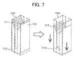
- Fig. 7 shows the task to be achieved for allowing the amorphous core to stand for assembly, which will be described hereinafter.
- US 5 608 371 discloses an amorphous transformer comprising an amorphous core formed of an amorphous material with a lap provided at an upper portion and allowed to stand in substantially a vertical direction while being supported at a core support member, and a coil which is fitted with the amorphous core, wherein the core support member is formed by integrating a core support member for supporting a side surface of the amorphous core and a corner support member for supporting a corner portion of the core.
- the present invention seeks to allow the amorphous core to stand in good condition for preventing sink of the corner portion of the core that is let stand, thus smoothly assembling the core and the coil.
- the present invention provides an amorphous transformer according to claim 1 and a method of manufacturing an amorphous transformer according to claim 3.
- the core support member is provided in substantially a vertical direction along at least one of the side surfaces of the core.
- the corner support member has a shape which follows an R (radius) of the corner portion of the core.
- the core and the coil are assembled by inserting the amorphous core and the core support member for supporting the side surface of the amorphous core into the coil.
- the present invention provides an amorphous transformer which includes an amorphous core formed of an amorphous material with a lap provided at an upper portion and allowed to stand in substantially a vertical direction while being supported at a core support member, and a coil which is fitted with the amorphous core.
- the core member has a box-like shape, one end of which allows the core to be inserted, and the other end of which is provided with a gap at a portion corresponding to the corner portion of the core.
- a corner support member is formed by filling the gap with metal sticks.
- the present invention allows the core for the amorphous material to stand so that the coil is smoothly fitted while minimizing the load to the amorphous core and the coil in the state where the core is let stand.
- Approach to the problem of the core corner portion which sinks owing to its own weight may further be improved compared to the related art, thus simplifying bonding of the lap and improving bonding.
- FIGs. 1A to 1D are perspective views of an example of an amorphous transformer according to the present invention, showing a series of operations for assembling the coil with the amorphous core. This example will be described with respect to the use of 3-phase 5-leg amorphous core transformer.
- Fig. 1A illustrates a core support member 100 for supporting an amorphous core, and a corner support member 101 for preventing sink of a corner portion of the amorphous core.
- the core support member 100 stands substantially in a vertical direction along the side surface of the wound amorphous core having the lap at the upper portion, and has a height substantially equal to the one in the state where the lap of the amorphous core is opened. However, the height is not limited to the one as described above.
- a gap 104 is formed between adjacent support plates 102 and 103, through which a wound coil 120 is fitted with the core while having the lap opened. The core 110 and the support plate 103 are inserted into the coil 120 and the lap is bonded.
- the corner support member 101 for the amorphous core is fabricated based on the radius R of the corner portion of the wound amorphous core, and provided on a portion corresponding to the corner portion of the core for the purpose of preventing sink of the corner portion of the amorphous core owing to its own weight.
- the core support member 100 and the corner support member 101 are integrated through welding so as not to be broken under the weight of the core.
- Fig. 1B shows the state where the amorphous core is set in the integrated structure of the core support member 100 and the corner support member 101.
- the length of the corner support member 101 is set to be substantially the same as width of the amorphous core.
- the corner support members 101 are provided at all the corner portions of the cores.
- Each of both ends and inner side of the core support member 100 has an L-like shape and a T-like shape, respectively. The resultant space of the respective support plates accommodates the cores.
- the core is set while being hung from above.
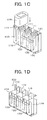
- Fig. 1C shows the state where the amorphous core is set in the integrated structure of the core support member 100 and the corner support member 101, which are further inserted into the coil 120.
- laps 111 of the two adjacent cores at the upper side, and the core support members 100 are inserted into the coil 120.
- the drawing represents the state where the left coil 120 is about to be fitted with the core from above.
- the coil 120 is hung down for positioning so as to be fitted with the core 110 for setting.
- Fig. 1D shows the state where the coil 120 is fitted with the core 110, and then the laps 114 of the amorphous core are bonded.
- the corner support members 101 are provided below the corner portion of the core so as to prevent sink of the corner portion of the core owing to its own weight.
- Example 1 allows the amorphous core 110 to stand, and the approach to the problem resulting from sink of the corner portion owing to the self weight of the amorphous core 110 is significantly improved compared to the related art. This makes it possible to easily conduct bonding of the lap portion 111, resulting in good bonding. As the corner support member suppresses the sink of the corner portion of the core, the properties may be retained in spite of aging variation.
- the amorphous core 110 is supported with the core support member 100 to stand, thus allowing smooth fitting of the coil in the self-supported state. This makes it possible to largely increase the work efficiency.
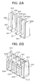
- Figs. 2A and 2B show the core assembly of the 3-phase 5-leg amorphous core transformer having the cores arranged in two rows, core support member 200, and corner support members 201.
- Fig. 2A is a perspective view of the core support member 200 and the corner support members 201 for arranging the cores in two rows.
- Each of the inner side and both ends of the core support member 200 has a cross-like shape and a T-like shape, respectively.
- the amorphous core is set in the space defined by a protruding support plate with cross-like shape, and the space defined by the side plate with T-like shape and the protruding support plate with cross-like shape.
- the corner support member 201 is provided at the portion corresponding to a corner portion 212 of the amorphous core to be set.
- the resultant structure is the same as the one shown in Fig. 1A .
- Fig. 2B is a perspective view showing the cores and coils of the 3-phase 5-leg amorphous transformer in two rows, which are set in the support member 200.
- assembly of the amorphous core and the coil will be described.
- the amorphous cores 210 are arranged in two rows at the protruding support plates 202, 203 with the cross-like shapes while having the laps 211 opened.
- the coil 220 is fitted with the adjacent inner sides of the cores.
- the single coil 220 is fitted with the inner support plate with cross-like shape and the cores in two rows altogether.
- the width of the transformer core shown in Fig. 2B is larger than that of the transformer core shown in Fig. 1D . Increase in the width of the core makes it possible to provide the transformer with large capacity.
- the cores in two rows may be arranged and set in the support members while having the laps 211 opened likewise the case having cores in a single row so that those cores are allowed to stand with the corner support members and the core support members. This makes it possible to smoothly fit the coil 220, thus remarkably improving workability.
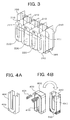
- Fig. 3 is a perspective view showing that the cores are arranged in the core support member 200 in two rows, the coils 220 are fitted, and the laps 211 of the cores are bonded for assembling.
- the structure shown in Fig. 3 is different from the one shown in Fig. 2B in a corner support member 301.
- the corner support member 301 shown in Fig. 3 has a support portion that is not continuous for accommodating the corner portion of the core, each of which has a predetermined width. A plurality of those support portions are arranged at substantially uniform intervals.
- the accommodating portion of the corner support member 301 has the same configuration as that of the corner portion of the core.
- Figs. 4A-4B shows another example of the core support member having a core support member 400 and a corner support member 401 not integrated.
- Fig. 4A is a perspective view of the core support member 400 of box shape.
- Fig. 4B represents a state where the amorphous core is inserted into the box-shape core support member 400, a core corner support member is inserted into the corner portion, which is then inverted upside down.
- the core support member 400 has a long box shape, that is, a cuboidal shape having one smallest side open so that the amorphous core is inserted.
- the corner portion at the other side has a space (gap) so that the corner portion of the core is supported, and a window 403 through which an object is externally inserted.
- the box-shaped core support member has a thin and long cut portion through which the coil is inserted so as to form the box-like shape into the U-like shape.
- the amorphous core is inserted from the open side of the box-shaped core support member 400, and the lap 411 is bonded. It is then inverted upside down as shown by the left drawing of Fig. 4B .
- thin metal sticks are inserted into the respective windows as the space (gap) at the corner portions of the core support member 400 for filling along the arc-shape of the corner portion of the transformer.
- the core support member 400 having the amorphous core inserted is further inverted upside down again as shown in the right drawing of Fig. 4B .
- the thus structured box-shape core support members are arranged in the single row as shown in Fig. 1D to form the 3-phase 5-leg amorphous core.
- the core support members as shown in Fig. 4B may be arranged in two rows likewise the one shown in Fig. 2B to increase the core width for coping with the transformer with large capacity.
- Fig. 5A to 5D show modified examples of the corner core support member.
- Fig. 5A shows the same structure as the one shown in Fig. 1A .
- the corner portion of the core is supported at the support member 201 which has a solid continuous structure shaped along the radius R of the corner portion of the core. If the support member with the aforementioned structure is formed of metal, the supporting function is sufficiently performed. However, because of the solid structure, increased weight tends to cause the entire structure to be heavy.
- Fig. 5B shows that a structure formed by combining a support plate 501 with the radius R and an L-shaped support plate 502 for supporting the plate.
- a structure formed by combining a support plate 501 with the radius R and an L-shaped support plate 502 for supporting the plate may intensify the strength.
- a hollow portion is defined by the plate 501 with the radius R and the L-shaped plate 502, and accordingly, the weight of the support member may be reduced.
- Fig. 5C shows a plurality of support plates 511 each with the radius R obtained by cutting the continuous L-shaped support plate 501 as shown in Fig. 5B in the predetermined dimension are arranged at predetermined intervals for supporting the corner portion of the core. This structure may further reduce the weight compared to the structure shown in Fig. 5B .
- Fig. 5D is a partially enlarged view of the structure shown in Fig. 4B .
- the corner support member is formed by inserting thin metal sticks into the space (gap) to be filled along the arc-like corner portion of the transformer. The structure follows the arc more closely as the stick becomes thinner.
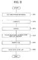
- Fig. 6 is a flowchart representing the method for assembling the amorphous transformer according to the present invention. Each step of the process will be described referring to the flowchart.
- the hoop-like wound amorphous material is pulled and cut in a predetermined length in step 601. Then the cut amorphous material with the predetermined length is positioned and laminated in laminating step 602.
- the core is subjected to rectangular shaping process (not shown) so as to have a U-like configuration.
- rectangular shaping process (not shown) so as to have a U-like configuration.
- the core After annealing the core, it is set in the support member in step 604. After setting the core in the core support member, the coil is fitted with the core and the core support member in coil fitting step 605. After fitting the coil, the lap for the core is bonded in lap bonding step 606. After finishing the lap bonding step, the assembly of the core and the coil is completed.
- the present invention is not limited to the example as described above, but may be changed into various forms.
- the example has been described in detail for explicitness of the present invention.
- the present invention is not limited to the one with all the structures which have been described.
- the structure of the example may be partially replaced with the other example, or added to the other example.
- the structure of each of the examples may be partially added, removed, and replaced as well.
- all the core support members may be integrally formed or separately formed.
- the dimension of the support member and the number of the portion in contact with the core may be added or reduced.
Landscapes
- Engineering & Computer Science (AREA)
- Power Engineering (AREA)
- Manufacturing & Machinery (AREA)
- Manufacturing Cores, Coils, And Magnets (AREA)
Claims (3)
- Amorpher Transformator mit einem aus einem amorphen Material gebildeten amorphen Kern, der eine Überlappung an einem oberen Abschnitt aufweist und im Wesentlichen in einer vertikalen Richtung unter Stützung durch ein Kernabstützungselement steht, und einer Spule, die mit dem amorphen Kern bestückt ist, wobei das Kernabstützungselement ein Kernabstützungselement zum Stützen einer Seitenfläche des amorphen Kerns und ein Eckabstützungselement zum Stützen eines KernEckabschnitts mit gekrümmter Fläche aufweist,
wobei das Eckabstützungselement eine Form aufweist, die der gekrümmten Fläche des Kern-Eckabschnitts folgt, wobei die Eckabstützung gebildet ist durch eine Kombination einer gekrümmten Stützplatte und einer die gekrümmte Platte stützenden L-förmigen Stützplatte, um eine Hohlstruktur zu bilden, und
wobei der amorphe Kern und das Kernabstützungselement so angeordnet sind, dass die Seitenfläche des amorphen Kerns in der Spule gestützt ist. - Amorpher Transformator nach Anspruch 1, wobei das Kernabstützungselement im Wesentlichen in einer vertikalen Richtung längs wenigstens einer der Seitenflächen des Kerns vorgesehen ist.
- Verfahren zum Herstellen eines amorphen Transformators, in dem ein aus einem amorphen Material gebildeter amorpher Kern mit einer Überlappung ausgebildet wird, die an einem oberen Abschnitt vorgesehen ist und es dem Kern erlaubt, im Wesentlichen in einer vertikalen Richtung unter Stützung durch ein Kernabstützungselement zu stehen, und eine Spule mit dem amorphen Kern bestückt wird, wobei
das Kernabstützungselement eine schachtelähnliche Form aufweist, deren eines Ende ein Einschieben des Kerns erlaubt und deren anderes Ende mit einem Spalt an einem Abschnitt versehen ist, der dem Eckabschnitt des Kerns entspricht, wobei
ein Eckabstützungselement durch Auffüllen des Spalts mit Metallstäben gebildet wird.
Priority Applications (1)
| Application Number | Priority Date | Filing Date | Title |
|---|---|---|---|
| EP15183696.2A EP2980813B1 (de) | 2010-12-27 | 2011-07-05 | Amorpher transformator |
Applications Claiming Priority (1)
| Application Number | Priority Date | Filing Date | Title |
|---|---|---|---|
| JP2010289858A JP5341058B2 (ja) | 2010-12-27 | 2010-12-27 | アモルファス変圧器 |
Related Child Applications (2)
| Application Number | Title | Priority Date | Filing Date |
|---|---|---|---|
| EP15183696.2A Division EP2980813B1 (de) | 2010-12-27 | 2011-07-05 | Amorpher transformator |
| EP15183696.2A Division-Into EP2980813B1 (de) | 2010-12-27 | 2011-07-05 | Amorpher transformator |
Publications (2)
| Publication Number | Publication Date |
|---|---|
| EP2474985A1 EP2474985A1 (de) | 2012-07-11 |
| EP2474985B1 true EP2474985B1 (de) | 2015-10-14 |
Family
ID=45715330
Family Applications (2)
| Application Number | Title | Priority Date | Filing Date |
|---|---|---|---|
| EP15183696.2A Not-in-force EP2980813B1 (de) | 2010-12-27 | 2011-07-05 | Amorpher transformator |
| EP11172669.1A Not-in-force EP2474985B1 (de) | 2010-12-27 | 2011-07-05 | Amorpher Transformator |
Family Applications Before (1)
| Application Number | Title | Priority Date | Filing Date |
|---|---|---|---|
| EP15183696.2A Not-in-force EP2980813B1 (de) | 2010-12-27 | 2011-07-05 | Amorpher transformator |
Country Status (4)
| Country | Link |
|---|---|
| US (2) | US8552830B2 (de) |
| EP (2) | EP2980813B1 (de) |
| JP (1) | JP5341058B2 (de) |
| CN (1) | CN102543379B (de) |
Families Citing this family (9)
| Publication number | Priority date | Publication date | Assignee | Title |
|---|---|---|---|---|
| DK2490229T3 (en) * | 2011-02-16 | 2018-07-16 | Hitachi Industry Equipment Systems Co Ltd | Transformer, amorphous transformer and method of manufacturing the transformer |
| CN103107006B (zh) * | 2013-02-04 | 2015-07-01 | 明珠电气有限公司 | 一种三相非晶合金干式接地变压器 |
| EP2975618B1 (de) | 2014-07-16 | 2019-05-29 | Siemens Aktiengesellschaft | Kern für eine elektrische Induktionseinrichtung |
| US10861634B2 (en) * | 2016-04-27 | 2020-12-08 | Hitachi, Ltd. | Stationary induction electric device |
| CN106252052A (zh) * | 2016-09-12 | 2016-12-21 | 安泰科技股份有限公司 | 一种非晶合金铁心变压器及其装配方法 |
| CN106981355B (zh) * | 2017-04-21 | 2019-04-02 | 卧龙电气集团股份有限公司 | 一种侧挂式非晶合金铁芯片竖立器 |
| JP7045973B2 (ja) * | 2018-11-12 | 2022-04-01 | 株式会社日立産機システム | 静止誘導機器用鉄心、静止誘導機器およびその製造方法 |
| CN109841400A (zh) * | 2019-03-28 | 2019-06-04 | 广州增变电气有限公司 | 一种非晶合金变压器铁心的装配装置及方法 |
| JP2025104969A (ja) * | 2023-12-28 | 2025-07-10 | 株式会社日立産機システム | アモルファス変圧器 |
Family Cites Families (27)
| Publication number | Priority date | Publication date | Assignee | Title |
|---|---|---|---|---|
| US2906977A (en) * | 1955-03-02 | 1959-09-29 | Sperry Rand Corp | Means of producing hipersil cores to facilitate mounting thereof |
| US2930012A (en) * | 1958-01-20 | 1960-03-22 | Westinghouse Air Brake Co | Inductive apparatus |
| US3662308A (en) * | 1971-04-29 | 1972-05-09 | Central Moloney Inc | Transformer core and coil mounting frame |
| US3774298A (en) * | 1972-06-29 | 1973-11-27 | Westinghouse Electric Corp | Method of constructing a transformer winding assembly |
| US4260975A (en) * | 1979-05-29 | 1981-04-07 | General Electric Company | Transformer with terminal board support and clamping-mounting structure |
| JPH041708Y2 (de) * | 1985-06-27 | 1992-01-21 | ||
| US4709471A (en) * | 1986-08-15 | 1987-12-01 | Westinghouse Electric Corp. | Method of making a magnetic core |
| JPS63248107A (ja) * | 1987-04-03 | 1988-10-14 | Toshiba Corp | 静止誘導電器 |
| US5083360A (en) * | 1988-09-28 | 1992-01-28 | Abb Power T&D Company, Inc. | Method of making a repairable amorphous metal transformer joint |
| US5226222A (en) | 1990-08-08 | 1993-07-13 | Daihen Corporation | Fabrication method for transformers with an amorphous core |
| JP2626370B2 (ja) * | 1991-11-20 | 1997-07-02 | 松下電器産業株式会社 | 非晶質磁芯変圧器 |
| JP3458119B2 (ja) * | 1993-10-01 | 2003-10-20 | 株式会社ダイヘン | 巻鉄心変圧器 |
| JP2854530B2 (ja) * | 1994-11-25 | 1999-02-03 | 愛知電機株式会社 | 巻鉄心変圧器及びその製造方法 |
| JPH0935973A (ja) * | 1995-07-21 | 1997-02-07 | Aichi Electric Co Ltd | アモルファス鉄心変圧器及びその製造方法 |
| JPH09129464A (ja) * | 1995-10-27 | 1997-05-16 | Aichi Electric Co Ltd | 三相巻鉄心の組立方法及び組立装置 |
| US5684446A (en) * | 1996-10-21 | 1997-11-04 | Abb Power T&D Company Inc. | Transformer core-coil frame attachment and ground |
| TW371768B (en) * | 1997-06-06 | 1999-10-11 | Hitachi Ltd | Amorphous transformer |
| JP2000021642A (ja) * | 1998-06-30 | 2000-01-21 | Hitachi Ltd | 巻鉄心変圧器及びその製造方法 |
| EP0977214B1 (de) * | 1998-07-31 | 2004-11-24 | Hitachi, Ltd. | Transformatorkern aus amorphem Metall |
| JP3868676B2 (ja) * | 1999-08-19 | 2007-01-17 | 東芝エフエーシステムエンジニアリング株式会社 | 巻鉄心変圧器 |
| JP2001196234A (ja) | 2000-01-14 | 2001-07-19 | Hitachi Ltd | アモルファス鉄心モ−ルド変圧器及びその製造方法 |
| JP2001244121A (ja) * | 2000-03-01 | 2001-09-07 | Hitachi Ltd | アモルファス鉄心変圧器 |
| JP2005286169A (ja) * | 2004-03-30 | 2005-10-13 | Toshiba Corp | 変圧器の巻鉄心の製造方法及びその製造装置 |
| CN2888612Y (zh) * | 2006-03-31 | 2007-04-11 | 江苏华鹏变压器有限公司 | 变压器下轭铁芯的支撑架 |
| CN2904232Y (zh) * | 2006-05-31 | 2007-05-23 | 天津泰达节能技术投资咨询有限公司 | 一种水平放置的节能型浇注变压器 |
| JP4948363B2 (ja) * | 2007-11-08 | 2012-06-06 | 株式会社日立産機システム | 変圧器 |
| US20090128276A1 (en) * | 2007-11-19 | 2009-05-21 | John Horowy | Light weight reworkable inductor |
-
2010
- 2010-12-27 JP JP2010289858A patent/JP5341058B2/ja active Active
-
2011
- 2011-07-05 EP EP15183696.2A patent/EP2980813B1/de not_active Not-in-force
- 2011-07-05 EP EP11172669.1A patent/EP2474985B1/de not_active Not-in-force
- 2011-07-15 US US13/184,155 patent/US8552830B2/en not_active Expired - Fee Related
- 2011-07-19 CN CN201110205935.XA patent/CN102543379B/zh not_active Expired - Fee Related
-
2013
- 2013-09-30 US US14/042,073 patent/US9041503B2/en not_active Expired - Fee Related
Also Published As
| Publication number | Publication date |
|---|---|
| US9041503B2 (en) | 2015-05-26 |
| US20140028428A1 (en) | 2014-01-30 |
| US8552830B2 (en) | 2013-10-08 |
| US20120161915A1 (en) | 2012-06-28 |
| JP5341058B2 (ja) | 2013-11-13 |
| CN102543379B (zh) | 2016-01-20 |
| EP2980813A1 (de) | 2016-02-03 |
| EP2474985A1 (de) | 2012-07-11 |
| EP2980813B1 (de) | 2017-11-01 |
| JP2012138469A (ja) | 2012-07-19 |
| CN102543379A (zh) | 2012-07-04 |
Similar Documents
| Publication | Publication Date | Title |
|---|---|---|
| US9041503B2 (en) | Amorphous transformer | |
| TWI621139B (zh) | transformer | |
| EP3306626A1 (de) | Gestapelte kernstruktur und transformator damit | |
| JP2005286169A (ja) | 変圧器の巻鉄心の製造方法及びその製造装置 | |
| JP6937584B2 (ja) | 静止誘導電器用鉄心 | |
| CN103370752B (zh) | 具有带互锁构件的芯部框架的变压器 | |
| KR101853795B1 (ko) | 저손실 경량화 변압기 및 이의 제조방법 | |
| JP5676414B2 (ja) | アモルファス鉄心変圧器 | |
| US9230729B2 (en) | Transformer, amorphous transformer and method of manufacturing the transformer | |
| JP6963493B2 (ja) | ハイブリッド鉄心変圧器 | |
| JP4722589B2 (ja) | 固定子積層鉄心 | |
| JP5661878B2 (ja) | アモルファス変圧器 | |
| JP6320150B2 (ja) | アモルファス変圧器 | |
| CN217881106U (zh) | 非晶合金立体卷铁心 | |
| CN111180170B (zh) | 静止感应设备用铁芯、静止感应设备及其制造方法 | |
| JP4369164B2 (ja) | アモルファス鉄心変圧器の製造方法 | |
| JP6491835B2 (ja) | 静止誘導電器 | |
| JP2019062144A (ja) | 変圧器およびその製造方法 | |
| CN115206645A (zh) | 非晶合金立体卷铁心 | |
| JP7032257B2 (ja) | 変圧器および積鉄心 | |
| KR100543644B1 (ko) | 변압기용 코어 및 그 제조방법 | |
| JP2006120879A (ja) | アモルファス巻鉄心変圧器 | |
| KR100836892B1 (ko) | 카본대를 삽입하여 고정지지하는 코너부 지지대 및 제조방법 | |
| JPS59178712A (ja) | 積層鉄心組立て体 | |
| JPH07118423B2 (ja) | 変圧器 |
Legal Events
| Date | Code | Title | Description |
|---|---|---|---|
| PUAI | Public reference made under article 153(3) epc to a published international application that has entered the european phase |
Free format text: ORIGINAL CODE: 0009012 |
|
| 17P | Request for examination filed |
Effective date: 20110722 |
|
| AK | Designated contracting states |
Kind code of ref document: A1 Designated state(s): AL AT BE BG CH CY CZ DE DK EE ES FI FR GB GR HR HU IE IS IT LI LT LU LV MC MK MT NL NO PL PT RO RS SE SI SK SM TR |
|
| AX | Request for extension of the european patent |
Extension state: BA ME |
|
| REG | Reference to a national code |
Ref country code: DE Ref legal event code: R079 Ref document number: 602011020516 Country of ref document: DE Free format text: PREVIOUS MAIN CLASS: H01F0027250000 Ipc: H01F0027060000 |
|
| RIC1 | Information provided on ipc code assigned before grant |
Ipc: H01F 41/02 20060101ALI20150309BHEP Ipc: H01F 27/06 20060101AFI20150309BHEP Ipc: H01F 27/25 20060101ALI20150309BHEP |
|
| GRAP | Despatch of communication of intention to grant a patent |
Free format text: ORIGINAL CODE: EPIDOSNIGR1 |
|
| INTG | Intention to grant announced |
Effective date: 20150428 |
|
| RIN1 | Information on inventor provided before grant (corrected) |
Inventor name: MIKOSHIBA, RYOSUKE Inventor name: HONMA, TOORU Inventor name: TAKAHASHI, TOSHIAKI Inventor name: ENDO, HIROYUKI Inventor name: NAKANOUE, KENJI |
|
| GRAS | Grant fee paid |
Free format text: ORIGINAL CODE: EPIDOSNIGR3 |
|
| GRAA | (expected) grant |
Free format text: ORIGINAL CODE: 0009210 |
|
| AK | Designated contracting states |
Kind code of ref document: B1 Designated state(s): AL AT BE BG CH CY CZ DE DK EE ES FI FR GB GR HR HU IE IS IT LI LT LU LV MC MK MT NL NO PL PT RO RS SE SI SK SM TR |
|
| REG | Reference to a national code |
Ref country code: GB Ref legal event code: FG4D |
|
| REG | Reference to a national code |
Ref country code: AT Ref legal event code: REF Ref document number: 755662 Country of ref document: AT Kind code of ref document: T Effective date: 20151015 Ref country code: CH Ref legal event code: EP |
|
| REG | Reference to a national code |
Ref country code: IE Ref legal event code: FG4D |
|
| REG | Reference to a national code |
Ref country code: DE Ref legal event code: R096 Ref document number: 602011020516 Country of ref document: DE |
|
| REG | Reference to a national code |
Ref country code: NL Ref legal event code: MP Effective date: 20151014 |
|
| REG | Reference to a national code |
Ref country code: LT Ref legal event code: MG4D |
|
| REG | Reference to a national code |
Ref country code: AT Ref legal event code: MK05 Ref document number: 755662 Country of ref document: AT Kind code of ref document: T Effective date: 20151014 |
|
| PG25 | Lapsed in a contracting state [announced via postgrant information from national office to epo] |
Ref country code: IT Free format text: LAPSE BECAUSE OF FAILURE TO SUBMIT A TRANSLATION OF THE DESCRIPTION OR TO PAY THE FEE WITHIN THE PRESCRIBED TIME-LIMIT Effective date: 20151014 Ref country code: NL Free format text: LAPSE BECAUSE OF FAILURE TO SUBMIT A TRANSLATION OF THE DESCRIPTION OR TO PAY THE FEE WITHIN THE PRESCRIBED TIME-LIMIT Effective date: 20151014 Ref country code: ES Free format text: LAPSE BECAUSE OF FAILURE TO SUBMIT A TRANSLATION OF THE DESCRIPTION OR TO PAY THE FEE WITHIN THE PRESCRIBED TIME-LIMIT Effective date: 20151014 Ref country code: HR Free format text: LAPSE BECAUSE OF FAILURE TO SUBMIT A TRANSLATION OF THE DESCRIPTION OR TO PAY THE FEE WITHIN THE PRESCRIBED TIME-LIMIT Effective date: 20151014 Ref country code: NO Free format text: LAPSE BECAUSE OF FAILURE TO SUBMIT A TRANSLATION OF THE DESCRIPTION OR TO PAY THE FEE WITHIN THE PRESCRIBED TIME-LIMIT Effective date: 20160114 Ref country code: LT Free format text: LAPSE BECAUSE OF FAILURE TO SUBMIT A TRANSLATION OF THE DESCRIPTION OR TO PAY THE FEE WITHIN THE PRESCRIBED TIME-LIMIT Effective date: 20151014 Ref country code: IS Free format text: LAPSE BECAUSE OF FAILURE TO SUBMIT A TRANSLATION OF THE DESCRIPTION OR TO PAY THE FEE WITHIN THE PRESCRIBED TIME-LIMIT Effective date: 20160214 |
|
| PG25 | Lapsed in a contracting state [announced via postgrant information from national office to epo] |
Ref country code: PT Free format text: LAPSE BECAUSE OF FAILURE TO SUBMIT A TRANSLATION OF THE DESCRIPTION OR TO PAY THE FEE WITHIN THE PRESCRIBED TIME-LIMIT Effective date: 20160215 Ref country code: LV Free format text: LAPSE BECAUSE OF FAILURE TO SUBMIT A TRANSLATION OF THE DESCRIPTION OR TO PAY THE FEE WITHIN THE PRESCRIBED TIME-LIMIT Effective date: 20151014 Ref country code: AT Free format text: LAPSE BECAUSE OF FAILURE TO SUBMIT A TRANSLATION OF THE DESCRIPTION OR TO PAY THE FEE WITHIN THE PRESCRIBED TIME-LIMIT Effective date: 20151014 Ref country code: PL Free format text: LAPSE BECAUSE OF FAILURE TO SUBMIT A TRANSLATION OF THE DESCRIPTION OR TO PAY THE FEE WITHIN THE PRESCRIBED TIME-LIMIT Effective date: 20151014 Ref country code: RS Free format text: LAPSE BECAUSE OF FAILURE TO SUBMIT A TRANSLATION OF THE DESCRIPTION OR TO PAY THE FEE WITHIN THE PRESCRIBED TIME-LIMIT Effective date: 20151014 Ref country code: GR Free format text: LAPSE BECAUSE OF FAILURE TO SUBMIT A TRANSLATION OF THE DESCRIPTION OR TO PAY THE FEE WITHIN THE PRESCRIBED TIME-LIMIT Effective date: 20160115 Ref country code: SE Free format text: LAPSE BECAUSE OF FAILURE TO SUBMIT A TRANSLATION OF THE DESCRIPTION OR TO PAY THE FEE WITHIN THE PRESCRIBED TIME-LIMIT Effective date: 20151014 Ref country code: FI Free format text: LAPSE BECAUSE OF FAILURE TO SUBMIT A TRANSLATION OF THE DESCRIPTION OR TO PAY THE FEE WITHIN THE PRESCRIBED TIME-LIMIT Effective date: 20151014 |
|
| REG | Reference to a national code |
Ref country code: DE Ref legal event code: R097 Ref document number: 602011020516 Country of ref document: DE |
|
| PG25 | Lapsed in a contracting state [announced via postgrant information from national office to epo] |
Ref country code: CZ Free format text: LAPSE BECAUSE OF FAILURE TO SUBMIT A TRANSLATION OF THE DESCRIPTION OR TO PAY THE FEE WITHIN THE PRESCRIBED TIME-LIMIT Effective date: 20151014 |
|
| PLBE | No opposition filed within time limit |
Free format text: ORIGINAL CODE: 0009261 |
|
| STAA | Information on the status of an ep patent application or granted ep patent |
Free format text: STATUS: NO OPPOSITION FILED WITHIN TIME LIMIT |
|
| PG25 | Lapsed in a contracting state [announced via postgrant information from national office to epo] |
Ref country code: DK Free format text: LAPSE BECAUSE OF FAILURE TO SUBMIT A TRANSLATION OF THE DESCRIPTION OR TO PAY THE FEE WITHIN THE PRESCRIBED TIME-LIMIT Effective date: 20151014 Ref country code: SK Free format text: LAPSE BECAUSE OF FAILURE TO SUBMIT A TRANSLATION OF THE DESCRIPTION OR TO PAY THE FEE WITHIN THE PRESCRIBED TIME-LIMIT Effective date: 20151014 Ref country code: SM Free format text: LAPSE BECAUSE OF FAILURE TO SUBMIT A TRANSLATION OF THE DESCRIPTION OR TO PAY THE FEE WITHIN THE PRESCRIBED TIME-LIMIT Effective date: 20151014 Ref country code: EE Free format text: LAPSE BECAUSE OF FAILURE TO SUBMIT A TRANSLATION OF THE DESCRIPTION OR TO PAY THE FEE WITHIN THE PRESCRIBED TIME-LIMIT Effective date: 20151014 Ref country code: RO Free format text: LAPSE BECAUSE OF FAILURE TO SUBMIT A TRANSLATION OF THE DESCRIPTION OR TO PAY THE FEE WITHIN THE PRESCRIBED TIME-LIMIT Effective date: 20151014 |
|
| 26N | No opposition filed |
Effective date: 20160715 |
|
| PG25 | Lapsed in a contracting state [announced via postgrant information from national office to epo] |
Ref country code: SI Free format text: LAPSE BECAUSE OF FAILURE TO SUBMIT A TRANSLATION OF THE DESCRIPTION OR TO PAY THE FEE WITHIN THE PRESCRIBED TIME-LIMIT Effective date: 20151014 |
|
| PG25 | Lapsed in a contracting state [announced via postgrant information from national office to epo] |
Ref country code: BE Free format text: LAPSE BECAUSE OF FAILURE TO SUBMIT A TRANSLATION OF THE DESCRIPTION OR TO PAY THE FEE WITHIN THE PRESCRIBED TIME-LIMIT Effective date: 20151014 |
|
| REG | Reference to a national code |
Ref country code: CH Ref legal event code: PL |
|
| GBPC | Gb: european patent ceased through non-payment of renewal fee |
Effective date: 20160705 |
|
| PG25 | Lapsed in a contracting state [announced via postgrant information from national office to epo] |
Ref country code: MC Free format text: LAPSE BECAUSE OF FAILURE TO SUBMIT A TRANSLATION OF THE DESCRIPTION OR TO PAY THE FEE WITHIN THE PRESCRIBED TIME-LIMIT Effective date: 20151014 |
|
| PG25 | Lapsed in a contracting state [announced via postgrant information from national office to epo] |
Ref country code: LI Free format text: LAPSE BECAUSE OF NON-PAYMENT OF DUE FEES Effective date: 20160731 Ref country code: CH Free format text: LAPSE BECAUSE OF NON-PAYMENT OF DUE FEES Effective date: 20160731 Ref country code: FR Free format text: LAPSE BECAUSE OF NON-PAYMENT OF DUE FEES Effective date: 20160801 |
|
| REG | Reference to a national code |
Ref country code: FR Ref legal event code: ST Effective date: 20170331 |
|
| REG | Reference to a national code |
Ref country code: IE Ref legal event code: MM4A |
|
| PG25 | Lapsed in a contracting state [announced via postgrant information from national office to epo] |
Ref country code: GB Free format text: LAPSE BECAUSE OF NON-PAYMENT OF DUE FEES Effective date: 20160705 |
|
| PG25 | Lapsed in a contracting state [announced via postgrant information from national office to epo] |
Ref country code: IE Free format text: LAPSE BECAUSE OF NON-PAYMENT OF DUE FEES Effective date: 20160705 |
|
| PG25 | Lapsed in a contracting state [announced via postgrant information from national office to epo] |
Ref country code: LU Free format text: LAPSE BECAUSE OF NON-PAYMENT OF DUE FEES Effective date: 20160705 |
|
| PG25 | Lapsed in a contracting state [announced via postgrant information from national office to epo] |
Ref country code: HU Free format text: LAPSE BECAUSE OF FAILURE TO SUBMIT A TRANSLATION OF THE DESCRIPTION OR TO PAY THE FEE WITHIN THE PRESCRIBED TIME-LIMIT; INVALID AB INITIO Effective date: 20110705 Ref country code: CY Free format text: LAPSE BECAUSE OF FAILURE TO SUBMIT A TRANSLATION OF THE DESCRIPTION OR TO PAY THE FEE WITHIN THE PRESCRIBED TIME-LIMIT Effective date: 20151014 |
|
| PG25 | Lapsed in a contracting state [announced via postgrant information from national office to epo] |
Ref country code: TR Free format text: LAPSE BECAUSE OF FAILURE TO SUBMIT A TRANSLATION OF THE DESCRIPTION OR TO PAY THE FEE WITHIN THE PRESCRIBED TIME-LIMIT Effective date: 20151014 Ref country code: MT Free format text: LAPSE BECAUSE OF NON-PAYMENT OF DUE FEES Effective date: 20160731 Ref country code: MK Free format text: LAPSE BECAUSE OF FAILURE TO SUBMIT A TRANSLATION OF THE DESCRIPTION OR TO PAY THE FEE WITHIN THE PRESCRIBED TIME-LIMIT Effective date: 20151014 |
|
| PG25 | Lapsed in a contracting state [announced via postgrant information from national office to epo] |
Ref country code: BG Free format text: LAPSE BECAUSE OF FAILURE TO SUBMIT A TRANSLATION OF THE DESCRIPTION OR TO PAY THE FEE WITHIN THE PRESCRIBED TIME-LIMIT Effective date: 20151014 |
|
| PG25 | Lapsed in a contracting state [announced via postgrant information from national office to epo] |
Ref country code: AL Free format text: LAPSE BECAUSE OF FAILURE TO SUBMIT A TRANSLATION OF THE DESCRIPTION OR TO PAY THE FEE WITHIN THE PRESCRIBED TIME-LIMIT Effective date: 20151014 |
|
| REG | Reference to a national code |
Ref country code: DE Ref legal event code: R082 Ref document number: 602011020516 Country of ref document: DE Representative=s name: MEWBURN ELLIS LLP, DE |
|
| PGFP | Annual fee paid to national office [announced via postgrant information from national office to epo] |
Ref country code: DE Payment date: 20200624 Year of fee payment: 10 |
|
| REG | Reference to a national code |
Ref country code: DE Ref legal event code: R119 Ref document number: 602011020516 Country of ref document: DE |
|
| PG25 | Lapsed in a contracting state [announced via postgrant information from national office to epo] |
Ref country code: DE Free format text: LAPSE BECAUSE OF NON-PAYMENT OF DUE FEES Effective date: 20220201 |