EP2475478B1 - Verfahren und vorrichtung zum stützen von längsstäben bei der herstellung von bewehrungselementen - Google Patents
Verfahren und vorrichtung zum stützen von längsstäben bei der herstellung von bewehrungselementen Download PDFInfo
- Publication number
- EP2475478B1 EP2475478B1 EP10773982.3A EP10773982A EP2475478B1 EP 2475478 B1 EP2475478 B1 EP 2475478B1 EP 10773982 A EP10773982 A EP 10773982A EP 2475478 B1 EP2475478 B1 EP 2475478B1
- Authority
- EP
- European Patent Office
- Prior art keywords
- longitudinal
- support member
- bars
- sleeves
- rotatable support
- Prior art date
- Legal status (The legal status is an assumption and is not a legal conclusion. Google has not performed a legal analysis and makes no representation as to the accuracy of the status listed.)
- Not-in-force
Links
Images



Classifications
-
- B—PERFORMING OPERATIONS; TRANSPORTING
- B21—MECHANICAL METAL-WORKING WITHOUT ESSENTIALLY REMOVING MATERIAL; PUNCHING METAL
- B21F—WORKING OR PROCESSING OF METAL WIRE
- B21F27/00—Making wire network, i.e. wire nets
- B21F27/12—Making special types or portions of network by methods or means specially adapted therefor
- B21F27/121—Making special types or portions of network by methods or means specially adapted therefor of tubular form, e.g. as reinforcements for pipes or pillars
- B21F27/122—Making special types or portions of network by methods or means specially adapted therefor of tubular form, e.g. as reinforcements for pipes or pillars by attaching a continuous stirrup to longitudinal wires
- B21F27/124—Making special types or portions of network by methods or means specially adapted therefor of tubular form, e.g. as reinforcements for pipes or pillars by attaching a continuous stirrup to longitudinal wires applied by rotation
Definitions
- the present invention regards a device for supporting longitudinal bars in machines for manufacturing metal cages, in particular for reinforced concrete.
- metal cages are used, often cylindrical shaped, constituted by a series of longitudinal iron bars, outside which is placed a rod spiral-wound on the same bars, according to a suitably predetermined pitch.
- the longitudinal bars are distributed according to a suitable geometrical profile, usually cylindrical; nevertheless examples of piles and pillars having different geometries are not lacking, for example asymmetrical, elliptic, prismatic and the like.
- patent EP 0035477 illustrates a machine for manufacturing cages with spiral-winding comprising a driving flange and a freely sliding flange carried by a trolley which can move in front of the driving head, both flanges being prearranged to support the longitudinal bars in predetermined positions.
- the bars are rotated by the aforesaid flanges, while the metal wire, unwound from a lateral coil and brought in longitudinal motion, progressively spiral-winds about the same bars.
- patent IT 1216960 discloses the use of rotating members constituted by disks provided with holes arranged at various radial distances from the cage forming longitudinal axis, coinciding with the machine rotation axis, for the insertion of the longitudinal bars.
- the longitudinal bars are associated with the aforementioned holes of the rotating members by means of suitable sleeves.
- Patent US 3,579,259 illustrates an analogous support system for the bars wherein the rotating members are constituted by disks having a series of radial eyelets, regularly distanced, designed to be engaged by the longitudinal bars.
- the bars are fastened in the desired position by means of suitable blocking members.
- the support system for the bars illustrated in patent WO 2005/084848 (with family the patent publication IT UD2004 0095 ) belongs to the same typology.
- Patent publication ITPS20010012 illustrates a different support modality for the longitudinal bars wherein the rotating members are provided with an interchangeable ring on which the bar insertion sleeves can be applied, in different positions.
- Patent publication JP 07-144243 discloses a device for the production of X-shaped bar arrangement assembly, comprising a pair of carriages movable so as to get mutually distanced or approached. Each carriage carries a rotary shaft parallel to the carriage moving direction and provided with a rotating body. Such rotating bodies each provide a gage plate having penetrating hole for positioning the end of a bar, and a cross shaped element to support a reinforcing bar fixing frame on the side of the front end of the rotary shaft.
- Patent US 2,861,602 teaches a collapsible mandrel for manufacturing reinforcing cages, comprising a central shaft, a plurality of elongated U-shaped elongated bars parallel to the central shaft, and a plurality of further U-shaped elongated bars which act as sleeves for receiving the longitudinal bars of the reinforcing cages being manufactured.
- cages with longitudinal bars having a suitably folded end In the specified field, the need is felt for manufacturing cages with longitudinal bars having a suitably folded end.
- the use of cages of this type is required, for example, to better distribute the weight of the cage, or to prevent a sinking of the same cage in the ground, due to its own weight, which would enable harmful corrosion phenomena.
- the use of bars with the folded end is useful for safety reasons, to prevent accidental injuries of the operators on the sharp ends protruding from the bars.
- the task of the present invention is that of solving the aforementioned problem, devising a method and a device that allow to operate in an optimal way the support of the longitudinal bars in machines for manufacturing metal cages for reinforced concrete and the like, in particular enabling the mounting of bars having at least one folded end.
- a further scope of the present invention is that of providing a device that allows to orient in the desired manner the aforesaid folded end of the longitudinal bars.
- a further object of the invention is that of devising a support device for bars having a simple conception, a securely reliable functioning and versatile use, as well as relatively economic cost.
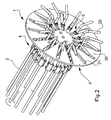
- the support device for longitudinal bars 2 in a machine for manufacturing metal cages, in particular for the reinforcement of piles, reinforced concrete pillars and the like, is indicated in its entirety with 1.
- the bars 2 have a suitable folded end 20.
- the metal cage to be manufactured is constituted by a series of longitudinal bars arranged parallel and made integral, according to the predetermined geometry, by means of a metal wire spiral-wound on the same bars, according to a suitable predetermined pitch.
- the bars suitable to shape the metal cage are arranged according to a circular transverse profile, so as to determine the manufacturing of a cylindrical pile.
- the support device 1 provides a rotating member 3 suitable to support the longitudinal bars 2 in the fastening positions for the formation of the cage.
- Such a rotatable support member 3 is suitable to be actuated in rotation by a suitable motor member, according to the axis of the forming cage, in order to put in rotation the longitudinal bars 2 during the formation of the cage.
- the rotatable support member 3 comprises a disk 30 suitable to be arranged on a plane orthogonal to the cited axis of the forming cage.
- the disk 30 has a series of slots 31 extended in radial direction and angularly distributed in a regular manner.
- the disk 30 is suitable to carry, at the slots 31, a plurality of bushings or sleeves 4 suitable to receive the longitudinal bars 2.
- the sleeves 4 are suitable to be fastened in adjustable positions respectively at the radial slots 31 of the disk 30, through respective connection members 5.
- the sleeves 4 are made from a first element 41 and a second element 42 having a complementary shape, suitable to be associated with each other in a way as to conjointly define, in the position of reciprocal union, a tubular opening 40 for the passage of the bar 2 to be supported.
- first and second element 41, 42 of the sleeves 4 are constituted for example by trolley-shaped prismatic bodies, respectively having a first channel 43 and a second channel 44.
- the channels 43, 44 have equal semicircular profile in a way as to constitute, in the position of reciprocal union of the elements 41 and 42, a cylindrical tubular opening 40.
- the channels 43, 44 it is possible to provide that the channels 43, 44 to have a different shape, so as to define a tubular opening for the passage of the bar 2 with a different profile, as an example prismatic.
- the channels 43, 44 are made differently from each other or otherwise that the tubular opening for the passage of the bar 2 is made by one only channel, shaped in a first trolley element 41, closed by a covering element made by the second element 42.
- the trolley elements 41, 42 are suitable to be tightened, in the position of reciprocal union, between a couple of plates 45 fastened by means of screw means 46.
- connection member 5 is constituted by a couple of plates 51, 52 suitable to be vice-tightened on the disk 30 of the rotatable support member 3 through a screw member 50 that crosses in mounting position a relative radial slot 31.
- a first plate 51 is integral with the first trolley element 41 of the sleeve 4 and rests in mounting position on a side of the disk 30, while the second plate 52 is free and rests in mounting position on the opposite side of the disk 30.
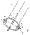
- FIGS 5 and 6 is illustrated a different embodiment of the support device according to the invention, wherein the rotatable support member 3 comprises a ring 32 provided with circumferential slots 33.
- a rotatable support member 3 is of the type illustrated in patent publication WO 2009/104157 .
- the ring 32 is realized by two concentric portions so as to define a continuous circumferential eyelet.
- the ring 32 is arranged on a plane orthogonal to the axis of the forming cage and is appropriately suitable to be constrained to the motion members by means of cross members not represented.
- Such a solution offers the advantage of freeing the central zone of the rotatable support member 3, for example for inserting auxiliary devices on the machine.
- the first and the second element 41, 42 of the sleeves 4 are constituted in this case by respective angular pieces, with squaring profile, suitable to be inserted in each other with sliding in longitudinal direction.
- the first element 41 has along the longitudinal edges respective guides 47 suitable to allow the sliding insertion of the second element 42.
- the tubular opening 40 for the passage of the bar 2 to be supported has a quadrilateral, in particular square, profile.
- the second element 42 is then fastened to the first element 41 by means of appropriate screw members.
- connection member 5 of the first element 41 of the sleeves 4 to the ring 32 of the rotatable support member 3 is constituted by an arm 53 which extends transversely from the element and has a slot 54 that is suitable to be crossed, in mounting position, by a screw member 55 for fastening to the provided circumferential slot 33 of the ring 32.
- the arm 53 is arranged substantially according to a direction diametral to the piece and is mounted radial to the ring 32.
- a rotatable support member 3 is constrained in a known way to the motion members of the machine, on a plane orthogonal to the axis of the forming cage.
- connection member 5 of the first element 41 of the sleeves 4 is constrained in a predetermined position along a relative radial slot 31 of the disk 30 or circumferential slot 33 of the ring 32.
- the connection member 5 of the first element 41 of the sleeves 4 is constrained in a predetermined position along a relative radial slot 31 of the disk 30 or circumferential slot 33 of the ring 32.
- the first element 41 of the sleeves 4 can be radially mounted outwards as well as inwards of the ring 32.
- the first element 41 of the sleeves 4 Once fastened the first element 41 of the sleeves 4, one provides to introduce the bar 2 to be supported, arranging it in the channel longitudinally defined by the same element 41.
- the bar 2 of the longitudinal reinforcement is more commonly introduced with the folded end 20 arranged frontally. It is to observe that such a folded end 20 of the bar 2 can freely pass, in an introduction step, through the radial slot 31 of the disk 30; obviously the passage is completely free, in case of the use of the ring 32 for the support of the bars 2.
- the end of the introduced bar 2, straight or folded, is then fastened to the corresponding disk which is keyed on the mobile head of the machine. In an analogous way one proceeds to the mounting of the successive bars 2.
- the described device attains the scope of making in an optimal manner the support of the longitudinal bars in machines for manufacturing metal cages for reinforced concrete and the like, in particular enabling the mounting of bars having at least one folded end.
- a characteristic of the device in hand is further constituted by the fact that it enables to rotate the longitudinal bars 2 about their own axis, in mounting step, so as to orient the folded end 20 in the wanted direction, as an example inwards of the cage or outwards as represented in figures 1 and 2 .
- the bars 2 are then blocked in order to maintain the folded end 20 in the wanted position.
- the embodiment of the invention may vary depending on the requirements.
Landscapes
- Engineering & Computer Science (AREA)
- Mechanical Engineering (AREA)
- Reinforcement Elements For Buildings (AREA)
- Branching, Merging, And Special Transfer Between Conveyors (AREA)
- Turning (AREA)
- Feeding Of Workpieces (AREA)
Claims (9)
- Vorrichtung zum Tragen der Stäbe für Maschinen zum Herstellen von Metallkörben, wobei diese Metallkörbe aus einer Reihe von Längsstäben (2) bestehen, die gemäß einem vorbestimmten geometrischen Profil angeordnet und mit Hilfe von mindestens einem Metalldraht fest miteinander verbunden sind, der mittels der Kombination einer Drehbewegung um eine mit der Achse des in Entstehung befindlichen Korbs übereinstimmende Achse und einer Verschiebebewegung spiralförmig um die Stäbe (2) gewunden wird, dadurch gekennzeichnet, dass diese Tragvorrichtung Folgendes umfasst:ein drehbares Tragelement (3), das geeignet ist, die Längsstäbe (2) in einer Befestigungsposition abzustützen, um den Korb zu bilden, wobei dieses drehbare Tragelement (3) Bereiche für den freien Durchgang aufweist, die das Einführen von Längsstäben (2) mit nach Möglichkeit gebogenen Enden ermöglichen,eine Vielzahl von Muffen (4), die geeignet sind, die Längsstäbe (2) aufzunehmen, wobei jede Muffe (4) jeweils ein erstes Element (41), das einen ersten Längskanal (43) aufweist, und ein zweites Element (42) umfasst, das einen zweiten Längskanal (44) aufweist, wobei der erste und der zweite Durchgangslängskanal (43, 44) geeignet sind, den röhrenförmigen Raum dieser Muffe (4) zu bilden, wenn sie miteinander zusammengefügt sind; wobei das erste Element (41) mit Hilfe eines Anschlusselements (5) in einer verstellbaren Position am drehbaren Tragelement (3) befestigt werden kann.
- Vorrichtung nach Anspruch 1, dadurch gekennzeichnet, dass das erste und das zweite Element (41, 42) der Muffen (4) aus jeweiligen Winkelprofilen bestehen, die durch eine Verschiebung in Längsrichtung ineinander gesteckt werden können.
- Vorrichtung nach Anspruch 2, dadurch gekennzeichnet, dass die Winkelprofile ein quadratisches Profil haben, so dass sie einen röhrenförmigen Raum (40) für den Durchgang des Stabs (2) mit einem Viereckprofil bilden.
- Vorrichtung nach Anspruch 2, dadurch gekennzeichnet, dass das erste Element (41) der Muffen (4) entlang der Längskanten jeweilige Führungen (47) aufweist, die das Einschieben des zweiten Elements (42) ermöglichen können.
- Vorrichtung nach Anspruch 1, dadurch gekennzeichnet, dass das erste und das zweite Element (41, 42) der Muffen (4) aus schieberförmigen prismatischen Körpern bestehen, die jeweils einen ersten und einen zweiten Kanal (43, 44) mit halbkreisförmigem Profil aufweisen, um gemeinsam einen zylindrischen röhrenförmigen Raum (40) für den Durchgang des zu tragenden Stabs (2) zu definieren.
- Vorrichtung nach Anspruch 1, dadurch gekennzeichnet, dass das Drehtragelement (3) eine Scheibe (30) umfasst, die in einer zur Achse des in Entstehung befindlichen Korbs rechtwinkligen Ebene angeordnet sein kann und eine Reihe von sich in radialer Richtung erstreckenden Langlöchern (31) für die Befestigung des ersten Elements (41) der Muffen (4) in einer verstellbaren Position aufweist.
- Vorrichtung nach Anspruch 1, dadurch gekennzeichnet, dass das drehbare Tragelement (3) einen Ring (32) umfasst, der mit mindestens einem zirkumferenziellen Langloch (33) für die Befestigung des ersten Elements (41) der Muffen (4) in einer verstellbaren Position versehen ist.
- Vorrichtung nach Anspruch 7, dadurch gekennzeichnet, dass das Anschlusselement (5) des ersten Elements (41) der Muffen (4) einen Ausleger (53) umfasst, der sich quer zum diesem ersten Element (41) erstreckt und ein Langloch (54) aufweist, das von schraubenartigen Mitteln (55) zum Befestigen dieses Auslegers (53) an dem zirkumferenziellen Langloch (33) des Rings (32) in einer im Wesentlichen zum Ring (32) radialen Position durchquert werden kann, um die Einstellung der sowohl zirkumferenziellen als auch radialen Positionierung der Längsstäbe (2) auf dem drehbaren Tragelement (3) zu ermöglichen.
- Verfahren zum Montieren von Längsstäben in Maschinen zum Herstellen von Metallkörben, wobei diese Metallkörbe aus einer Reihe von Längsstäben (2) bestehen, die gemäß einem vorbestimmten geometrischen Profil angeordnet und mit Hilfe von mindestens einem Metalldraht fest miteinander verbunden sind, der mittels der Kombination einer Drehbewegung um eine mit der Achse des in Entstehung befindlichen Korbs übereinstimmende Achse und einer Verschiebebewegung spiralförmig um die Stäbe (2) gewunden wird, dadurch gekennzeichnet, dass es die folgenden Phasen umfasst:a. Bereitstellen eines drehbaren Tragelements (3), das geeignet ist, die Längsstäbe (2) in einer Befestigungsposition abzustützen, um den Korb zu bilden, wobei dieses drehbare Tragelement (3) Bereiche für den freien Durchgang aufweist, die das Einführen von Längsstäben (2) mit nach Möglichkeit gebogenen Enden ermöglichen;b. Bereitstellen einer Vielzahl von Muffen (4), wobei jede Muffe (4) jeweils ein erstes Element (41), das einen ersten Längskanal (43) aufweist, und ein zweites Element (42) umfasst, das einen zweiten Längskanal (44) aufweist, wobei der erste und der zweite Durchgangslängskanal (43, 44) den röhrenförmigen Raum dieser Muffe (4) bilden, wenn sie miteinander zusammengefügt sind;c. Fixieren eines ersten Elements (41) der Muffe in einer verstellbaren Position auf dem drehbaren Tragelement (3);d. Einführen eines entsprechenden Längsstabs (2) durch einen Bereich für den freien Durchgang des Drehtragelements (3) mit einem kopfseitig angeordneten gegebenenfalls gebogenen Ende (20) und
Anordnen des Längsstabs (2) im ersten Kanal (43) des ersten Elements (41) der Muffe, die auf dem drehbarem Tragelement (3) befestigt ist;e. Verbinden des zweiten Elements (42) mit dem ersten Element (41) zum Schließen des röhrenförmigen Raums und zum Halten des in das drehbare Tragelement (3) eingeführten Stabs (2);f. Fixieren der anderen Muffen (4) in analoger Weise am Drehtragelement (3).
Applications Claiming Priority (2)
| Application Number | Priority Date | Filing Date | Title |
|---|---|---|---|
| ITBO2009A000578A IT1395571B1 (it) | 2009-09-11 | 2009-09-11 | Dispositivo di supporto delle barre in macchine per realizzare gabbie metalliche |
| PCT/IB2010/054054 WO2011030297A1 (en) | 2009-09-11 | 2010-09-08 | Device for manufacturing reinforcement metal cages with support device for bars |
Publications (2)
| Publication Number | Publication Date |
|---|---|
| EP2475478A1 EP2475478A1 (de) | 2012-07-18 |
| EP2475478B1 true EP2475478B1 (de) | 2013-11-06 |
Family
ID=42139101
Family Applications (1)
| Application Number | Title | Priority Date | Filing Date |
|---|---|---|---|
| EP10773982.3A Not-in-force EP2475478B1 (de) | 2009-09-11 | 2010-09-08 | Verfahren und vorrichtung zum stützen von längsstäben bei der herstellung von bewehrungselementen |
Country Status (3)
| Country | Link |
|---|---|
| EP (1) | EP2475478B1 (de) |
| IT (1) | IT1395571B1 (de) |
| WO (1) | WO2011030297A1 (de) |
Cited By (1)
| Publication number | Priority date | Publication date | Assignee | Title |
|---|---|---|---|---|
| CN104646573A (zh) * | 2014-12-31 | 2015-05-27 | 山东建筑大学 | 钢筋骨架机端部纵筋可调节固定锁紧装置 |
Families Citing this family (1)
| Publication number | Priority date | Publication date | Assignee | Title |
|---|---|---|---|---|
| CN105618969A (zh) * | 2016-03-11 | 2016-06-01 | 山东建筑大学 | 钢筋骨架截面尺寸调节装置 |
Family Cites Families (7)
| Publication number | Priority date | Publication date | Assignee | Title |
|---|---|---|---|---|
| US2861602A (en) * | 1956-12-21 | 1958-11-25 | Anna M Sedges | Collapsible mandrel for manufacturing reinforcing cages |
| US3579259A (en) | 1969-06-23 | 1971-05-18 | Nippon Rocla Pipes Co Ltd | Apparatus for making a double-layer reinforcing cage for concrete pipes |
| IT1141782B (it) * | 1980-03-05 | 1986-10-08 | Rema Macchine Utensili Spa | Macchina formatrice di gabbie |
| IT1216960B (it) | 1987-03-11 | 1990-03-14 | Grilli Mario Corsini Emilio Pa | Procedimento per la fabbricazione di gabbie cilindriche per cemento armanto |
| JP2684541B2 (ja) * | 1993-09-30 | 1997-12-03 | 株式会社長谷工コーポレーション | X形配筋組立鉄筋の製造装置 |
| US20110230450A1 (en) | 2007-10-16 | 2011-09-22 | Vascular Biogenics Lts | Platelet-activating factor (paf) analogs and uses thereof |
| ITBO20080118A1 (it) * | 2008-02-21 | 2009-08-22 | Gricor Impianti S R L | Dispositivo di supporto delle barre in macchine per realizzare gabbie metalliche |
-
2009
- 2009-09-11 IT ITBO2009A000578A patent/IT1395571B1/it active
-
2010
- 2010-09-08 EP EP10773982.3A patent/EP2475478B1/de not_active Not-in-force
- 2010-09-08 WO PCT/IB2010/054054 patent/WO2011030297A1/en not_active Ceased
Cited By (1)
| Publication number | Priority date | Publication date | Assignee | Title |
|---|---|---|---|---|
| CN104646573A (zh) * | 2014-12-31 | 2015-05-27 | 山东建筑大学 | 钢筋骨架机端部纵筋可调节固定锁紧装置 |
Also Published As
| Publication number | Publication date |
|---|---|
| IT1395571B1 (it) | 2012-10-16 |
| ITBO20090578A1 (it) | 2011-03-12 |
| WO2011030297A1 (en) | 2011-03-17 |
| EP2475478A1 (de) | 2012-07-18 |
Similar Documents
| Publication | Publication Date | Title |
|---|---|---|
| EP3134642B1 (de) | Ausrichtwerkzeug, system und verfahren zur verbindung von windturbinenturmsegmenten | |
| US11305447B2 (en) | Pipe cutting machine with a controlled floating cutting mandrel, and cutting method | |
| WO2009013774A1 (en) | Machine used to assemble metal cages for reinforced concrete piles or similar items | |
| EP2600991B1 (de) | Verfahren und vorrichtung zur korrektur der torsionsbeanspruchung bei metallstäben | |
| WO2011066163A1 (en) | Rebar installation system and method of securing rebar | |
| US3592243A (en) | Method of fabricating pc concrete pipe reinforcing | |
| EP2265397B1 (de) | Stützvorrichtung für stangen in maschinen zur herstellung von metallkäfigen; verwendung der vorrichtung | |
| US6925705B2 (en) | Cage making apparatus | |
| KR20210123346A (ko) | 바를 작업하기 위한 머신 및 해당 작업 방법 | |
| US20170326610A1 (en) | Apparatus and method for forming a screw flight | |
| EP2475478A1 (de) | Vorrichtung zur herstellung von verstärkten metallkäfigen mit einer stützvorrichtung für stangen | |
| JP7816747B2 (ja) | 鉄筋籠組み立て装置及び鉄筋籠組み立て方法 | |
| WO2014184787A1 (en) | Apparatus for and method of manufacturing metal cages for conical pillars | |
| EP1366246B1 (de) | Einer vorrichtung zur herstellung von käfigen zugeordnetes bildungselement | |
| EP2358487A2 (de) | Verfahren und vorrichtung zur herstellung von spiralförmigen armierungen für armiertem beton | |
| EP2632618A2 (de) | Maschine zur herstellung von metallkäfigen | |
| WO2002070169A1 (en) | Cage making apparatus | |
| EP2331276B1 (de) | Verfahren und vorrichtung zur positionierung von stangen in maschinen zur herstellung von metallkäfigen | |
| EP2331275B1 (de) | Schweissverfahren in maschinen zur herstellung von metallkäfigen für stahlbeton und entsprechende maschine | |
| KR101413193B1 (ko) | 라운드 벤더 | |
| DE10030499B4 (de) | Montageeinheit zur Herstellung einer Tragzelle eines Luftschiffs | |
| KR101905787B1 (ko) | 두부보강장치 및 이를 이용한 두부보강장치 시공방법 | |
| EP3008164B1 (de) | Aufbauverfahren eines fermenters für eine biogasanlage | |
| DE2553481C3 (de) | Vorrichtung zum Herstellen eines Rohres aus einem Blechband | |
| GR1009768B (el) | Τηλεσκοπικος συναρμολογητης κλωβων οπλισμου σκυροδεματος |
Legal Events
| Date | Code | Title | Description |
|---|---|---|---|
| PUAI | Public reference made under article 153(3) epc to a published international application that has entered the european phase |
Free format text: ORIGINAL CODE: 0009012 |
|
| 17P | Request for examination filed |
Effective date: 20120411 |
|
| AK | Designated contracting states |
Kind code of ref document: A1 Designated state(s): AL AT BE BG CH CY CZ DE DK EE ES FI FR GB GR HR HU IE IS IT LI LT LU LV MC MK MT NL NO PL PT RO SE SI SK SM TR |
|
| DAX | Request for extension of the european patent (deleted) | ||
| GRAP | Despatch of communication of intention to grant a patent |
Free format text: ORIGINAL CODE: EPIDOSNIGR1 |
|
| INTG | Intention to grant announced |
Effective date: 20130408 |
|
| GRAS | Grant fee paid |
Free format text: ORIGINAL CODE: EPIDOSNIGR3 |
|
| GRAA | (expected) grant |
Free format text: ORIGINAL CODE: 0009210 |
|
| AK | Designated contracting states |
Kind code of ref document: B1 Designated state(s): AL AT BE BG CH CY CZ DE DK EE ES FI FR GB GR HR HU IE IS IT LI LT LU LV MC MK MT NL NO PL PT RO SE SI SK SM TR |
|
| REG | Reference to a national code |
Ref country code: GB Ref legal event code: FG4D |
|
| REG | Reference to a national code |
Ref country code: CH Ref legal event code: EP |
|
| REG | Reference to a national code |
Ref country code: AT Ref legal event code: REF Ref document number: 639093 Country of ref document: AT Kind code of ref document: T Effective date: 20131215 |
|
| REG | Reference to a national code |
Ref country code: IE Ref legal event code: FG4D |
|
| REG | Reference to a national code |
Ref country code: DE Ref legal event code: R096 Ref document number: 602010011593 Country of ref document: DE Effective date: 20140102 |
|
| REG | Reference to a national code |
Ref country code: NL Ref legal event code: T3 |
|
| REG | Reference to a national code |
Ref country code: AT Ref legal event code: MK05 Ref document number: 639093 Country of ref document: AT Kind code of ref document: T Effective date: 20131106 |
|
| REG | Reference to a national code |
Ref country code: LT Ref legal event code: MG4D |
|
| PG25 | Lapsed in a contracting state [announced via postgrant information from national office to epo] |
Ref country code: HR Free format text: LAPSE BECAUSE OF FAILURE TO SUBMIT A TRANSLATION OF THE DESCRIPTION OR TO PAY THE FEE WITHIN THE PRESCRIBED TIME-LIMIT Effective date: 20131106 Ref country code: NO Free format text: LAPSE BECAUSE OF FAILURE TO SUBMIT A TRANSLATION OF THE DESCRIPTION OR TO PAY THE FEE WITHIN THE PRESCRIBED TIME-LIMIT Effective date: 20140206 Ref country code: FI Free format text: LAPSE BECAUSE OF FAILURE TO SUBMIT A TRANSLATION OF THE DESCRIPTION OR TO PAY THE FEE WITHIN THE PRESCRIBED TIME-LIMIT Effective date: 20131106 Ref country code: IS Free format text: LAPSE BECAUSE OF FAILURE TO SUBMIT A TRANSLATION OF THE DESCRIPTION OR TO PAY THE FEE WITHIN THE PRESCRIBED TIME-LIMIT Effective date: 20140306 Ref country code: LT Free format text: LAPSE BECAUSE OF FAILURE TO SUBMIT A TRANSLATION OF THE DESCRIPTION OR TO PAY THE FEE WITHIN THE PRESCRIBED TIME-LIMIT Effective date: 20131106 Ref country code: SE Free format text: LAPSE BECAUSE OF FAILURE TO SUBMIT A TRANSLATION OF THE DESCRIPTION OR TO PAY THE FEE WITHIN THE PRESCRIBED TIME-LIMIT Effective date: 20131106 |
|
| PG25 | Lapsed in a contracting state [announced via postgrant information from national office to epo] |
Ref country code: AT Free format text: LAPSE BECAUSE OF FAILURE TO SUBMIT A TRANSLATION OF THE DESCRIPTION OR TO PAY THE FEE WITHIN THE PRESCRIBED TIME-LIMIT Effective date: 20131106 Ref country code: BE Free format text: LAPSE BECAUSE OF FAILURE TO SUBMIT A TRANSLATION OF THE DESCRIPTION OR TO PAY THE FEE WITHIN THE PRESCRIBED TIME-LIMIT Effective date: 20131106 Ref country code: LV Free format text: LAPSE BECAUSE OF FAILURE TO SUBMIT A TRANSLATION OF THE DESCRIPTION OR TO PAY THE FEE WITHIN THE PRESCRIBED TIME-LIMIT Effective date: 20131106 Ref country code: ES Free format text: LAPSE BECAUSE OF FAILURE TO SUBMIT A TRANSLATION OF THE DESCRIPTION OR TO PAY THE FEE WITHIN THE PRESCRIBED TIME-LIMIT Effective date: 20131106 |
|
| PG25 | Lapsed in a contracting state [announced via postgrant information from national office to epo] |
Ref country code: PT Free format text: LAPSE BECAUSE OF FAILURE TO SUBMIT A TRANSLATION OF THE DESCRIPTION OR TO PAY THE FEE WITHIN THE PRESCRIBED TIME-LIMIT Effective date: 20140306 |
|
| PG25 | Lapsed in a contracting state [announced via postgrant information from national office to epo] |
Ref country code: EE Free format text: LAPSE BECAUSE OF FAILURE TO SUBMIT A TRANSLATION OF THE DESCRIPTION OR TO PAY THE FEE WITHIN THE PRESCRIBED TIME-LIMIT Effective date: 20131106 |
|
| REG | Reference to a national code |
Ref country code: DE Ref legal event code: R097 Ref document number: 602010011593 Country of ref document: DE |
|
| PG25 | Lapsed in a contracting state [announced via postgrant information from national office to epo] |
Ref country code: SK Free format text: LAPSE BECAUSE OF FAILURE TO SUBMIT A TRANSLATION OF THE DESCRIPTION OR TO PAY THE FEE WITHIN THE PRESCRIBED TIME-LIMIT Effective date: 20131106 Ref country code: CZ Free format text: LAPSE BECAUSE OF FAILURE TO SUBMIT A TRANSLATION OF THE DESCRIPTION OR TO PAY THE FEE WITHIN THE PRESCRIBED TIME-LIMIT Effective date: 20131106 Ref country code: PL Free format text: LAPSE BECAUSE OF FAILURE TO SUBMIT A TRANSLATION OF THE DESCRIPTION OR TO PAY THE FEE WITHIN THE PRESCRIBED TIME-LIMIT Effective date: 20131106 Ref country code: RO Free format text: LAPSE BECAUSE OF FAILURE TO SUBMIT A TRANSLATION OF THE DESCRIPTION OR TO PAY THE FEE WITHIN THE PRESCRIBED TIME-LIMIT Effective date: 20131106 |
|
| PLBE | No opposition filed within time limit |
Free format text: ORIGINAL CODE: 0009261 |
|
| STAA | Information on the status of an ep patent application or granted ep patent |
Free format text: STATUS: NO OPPOSITION FILED WITHIN TIME LIMIT |
|
| PG25 | Lapsed in a contracting state [announced via postgrant information from national office to epo] |
Ref country code: DK Free format text: LAPSE BECAUSE OF FAILURE TO SUBMIT A TRANSLATION OF THE DESCRIPTION OR TO PAY THE FEE WITHIN THE PRESCRIBED TIME-LIMIT Effective date: 20131106 |
|
| 26N | No opposition filed |
Effective date: 20140807 |
|
| REG | Reference to a national code |
Ref country code: DE Ref legal event code: R097 Ref document number: 602010011593 Country of ref document: DE Effective date: 20140807 |
|
| PG25 | Lapsed in a contracting state [announced via postgrant information from national office to epo] |
Ref country code: SI Free format text: LAPSE BECAUSE OF FAILURE TO SUBMIT A TRANSLATION OF THE DESCRIPTION OR TO PAY THE FEE WITHIN THE PRESCRIBED TIME-LIMIT Effective date: 20131106 |
|
| PG25 | Lapsed in a contracting state [announced via postgrant information from national office to epo] |
Ref country code: MC Free format text: LAPSE BECAUSE OF FAILURE TO SUBMIT A TRANSLATION OF THE DESCRIPTION OR TO PAY THE FEE WITHIN THE PRESCRIBED TIME-LIMIT Effective date: 20131106 Ref country code: LU Free format text: LAPSE BECAUSE OF FAILURE TO SUBMIT A TRANSLATION OF THE DESCRIPTION OR TO PAY THE FEE WITHIN THE PRESCRIBED TIME-LIMIT Effective date: 20140908 |
|
| REG | Reference to a national code |
Ref country code: CH Ref legal event code: PL |
|
| GBPC | Gb: european patent ceased through non-payment of renewal fee |
Effective date: 20140908 |
|
| REG | Reference to a national code |
Ref country code: IE Ref legal event code: MM4A |
|
| REG | Reference to a national code |
Ref country code: FR Ref legal event code: ST Effective date: 20150529 |
|
| PG25 | Lapsed in a contracting state [announced via postgrant information from national office to epo] |
Ref country code: CH Free format text: LAPSE BECAUSE OF NON-PAYMENT OF DUE FEES Effective date: 20140930 Ref country code: GB Free format text: LAPSE BECAUSE OF NON-PAYMENT OF DUE FEES Effective date: 20140908 Ref country code: LI Free format text: LAPSE BECAUSE OF NON-PAYMENT OF DUE FEES Effective date: 20140930 |
|
| PG25 | Lapsed in a contracting state [announced via postgrant information from national office to epo] |
Ref country code: FR Free format text: LAPSE BECAUSE OF NON-PAYMENT OF DUE FEES Effective date: 20140930 Ref country code: IE Free format text: LAPSE BECAUSE OF NON-PAYMENT OF DUE FEES Effective date: 20140908 |
|
| PGFP | Annual fee paid to national office [announced via postgrant information from national office to epo] |
Ref country code: DE Payment date: 20151001 Year of fee payment: 6 |
|
| PGFP | Annual fee paid to national office [announced via postgrant information from national office to epo] |
Ref country code: NL Payment date: 20150922 Year of fee payment: 6 |
|
| PG25 | Lapsed in a contracting state [announced via postgrant information from national office to epo] |
Ref country code: SM Free format text: LAPSE BECAUSE OF FAILURE TO SUBMIT A TRANSLATION OF THE DESCRIPTION OR TO PAY THE FEE WITHIN THE PRESCRIBED TIME-LIMIT Effective date: 20131106 |
|
| PG25 | Lapsed in a contracting state [announced via postgrant information from national office to epo] |
Ref country code: MT Free format text: LAPSE BECAUSE OF FAILURE TO SUBMIT A TRANSLATION OF THE DESCRIPTION OR TO PAY THE FEE WITHIN THE PRESCRIBED TIME-LIMIT Effective date: 20131106 Ref country code: BG Free format text: LAPSE BECAUSE OF FAILURE TO SUBMIT A TRANSLATION OF THE DESCRIPTION OR TO PAY THE FEE WITHIN THE PRESCRIBED TIME-LIMIT Effective date: 20131106 Ref country code: CY Free format text: LAPSE BECAUSE OF FAILURE TO SUBMIT A TRANSLATION OF THE DESCRIPTION OR TO PAY THE FEE WITHIN THE PRESCRIBED TIME-LIMIT Effective date: 20131106 Ref country code: GR Free format text: LAPSE BECAUSE OF FAILURE TO SUBMIT A TRANSLATION OF THE DESCRIPTION OR TO PAY THE FEE WITHIN THE PRESCRIBED TIME-LIMIT Effective date: 20140207 |
|
| PG25 | Lapsed in a contracting state [announced via postgrant information from national office to epo] |
Ref country code: HU Free format text: LAPSE BECAUSE OF FAILURE TO SUBMIT A TRANSLATION OF THE DESCRIPTION OR TO PAY THE FEE WITHIN THE PRESCRIBED TIME-LIMIT; INVALID AB INITIO Effective date: 20100908 Ref country code: TR Free format text: LAPSE BECAUSE OF FAILURE TO SUBMIT A TRANSLATION OF THE DESCRIPTION OR TO PAY THE FEE WITHIN THE PRESCRIBED TIME-LIMIT Effective date: 20131106 |
|
| REG | Reference to a national code |
Ref country code: DE Ref legal event code: R119 Ref document number: 602010011593 Country of ref document: DE |
|
| REG | Reference to a national code |
Ref country code: NL Ref legal event code: MM Effective date: 20161001 |
|
| PG25 | Lapsed in a contracting state [announced via postgrant information from national office to epo] |
Ref country code: NL Free format text: LAPSE BECAUSE OF NON-PAYMENT OF DUE FEES Effective date: 20161001 |
|
| PG25 | Lapsed in a contracting state [announced via postgrant information from national office to epo] |
Ref country code: DE Free format text: LAPSE BECAUSE OF NON-PAYMENT OF DUE FEES Effective date: 20170401 |
|
| PG25 | Lapsed in a contracting state [announced via postgrant information from national office to epo] |
Ref country code: MK Free format text: LAPSE BECAUSE OF FAILURE TO SUBMIT A TRANSLATION OF THE DESCRIPTION OR TO PAY THE FEE WITHIN THE PRESCRIBED TIME-LIMIT Effective date: 20131106 |
|
| PG25 | Lapsed in a contracting state [announced via postgrant information from national office to epo] |
Ref country code: AL Free format text: LAPSE BECAUSE OF FAILURE TO SUBMIT A TRANSLATION OF THE DESCRIPTION OR TO PAY THE FEE WITHIN THE PRESCRIBED TIME-LIMIT Effective date: 20131106 |
|
| P01 | Opt-out of the competence of the unified patent court (upc) registered |
Effective date: 20230502 |
|
| PGFP | Annual fee paid to national office [announced via postgrant information from national office to epo] |
Ref country code: IT Payment date: 20230929 Year of fee payment: 14 |
|
| PG25 | Lapsed in a contracting state [announced via postgrant information from national office to epo] |
Ref country code: IT Free format text: LAPSE BECAUSE OF NON-PAYMENT OF DUE FEES Effective date: 20240908 |