EP2475871B1 - Wartungsarmer hydraulischer turbinenmotor - Google Patents
Wartungsarmer hydraulischer turbinenmotor Download PDFInfo
- Publication number
- EP2475871B1 EP2475871B1 EP10770544.4A EP10770544A EP2475871B1 EP 2475871 B1 EP2475871 B1 EP 2475871B1 EP 10770544 A EP10770544 A EP 10770544A EP 2475871 B1 EP2475871 B1 EP 2475871B1
- Authority
- EP
- European Patent Office
- Prior art keywords
- turbine engine
- turbomachine
- seat
- guiding
- posts
- Prior art date
- Legal status (The legal status is an assumption and is not a legal conclusion. Google has not performed a legal analysis and makes no representation as to the accuracy of the status listed.)
- Active
Links
Images




Classifications
-
- F—MECHANICAL ENGINEERING; LIGHTING; HEATING; WEAPONS; BLASTING
- F03—MACHINES OR ENGINES FOR LIQUIDS; WIND, SPRING, OR WEIGHT MOTORS; PRODUCING MECHANICAL POWER OR A REACTIVE PROPULSIVE THRUST, NOT OTHERWISE PROVIDED FOR
- F03B—MACHINES OR ENGINES FOR LIQUIDS
- F03B13/00—Adaptations of machines or engines for special use; Combinations of machines or engines with driving or driven apparatus; Power stations or aggregates
- F03B13/12—Adaptations of machines or engines for special use; Combinations of machines or engines with driving or driven apparatus; Power stations or aggregates characterised by using wave or tide energy
- F03B13/26—Adaptations of machines or engines for special use; Combinations of machines or engines with driving or driven apparatus; Power stations or aggregates characterised by using wave or tide energy using tide energy
- F03B13/264—Adaptations of machines or engines for special use; Combinations of machines or engines with driving or driven apparatus; Power stations or aggregates characterised by using wave or tide energy using tide energy using the horizontal flow of water resulting from tide movement
-
- F—MECHANICAL ENGINEERING; LIGHTING; HEATING; WEAPONS; BLASTING
- F03—MACHINES OR ENGINES FOR LIQUIDS; WIND, SPRING, OR WEIGHT MOTORS; PRODUCING MECHANICAL POWER OR A REACTIVE PROPULSIVE THRUST, NOT OTHERWISE PROVIDED FOR
- F03B—MACHINES OR ENGINES FOR LIQUIDS
- F03B13/00—Adaptations of machines or engines for special use; Combinations of machines or engines with driving or driven apparatus; Power stations or aggregates
- F03B13/10—Submerged units incorporating electric generators or motors
-
- F—MECHANICAL ENGINEERING; LIGHTING; HEATING; WEAPONS; BLASTING
- F03—MACHINES OR ENGINES FOR LIQUIDS; WIND, SPRING, OR WEIGHT MOTORS; PRODUCING MECHANICAL POWER OR A REACTIVE PROPULSIVE THRUST, NOT OTHERWISE PROVIDED FOR
- F03B—MACHINES OR ENGINES FOR LIQUIDS
- F03B17/00—Other machines or engines
- F03B17/06—Other machines or engines using liquid flow with predominantly kinetic energy conversion, e.g. of swinging-flap type, "run-of-river", "ultra-low head"
- F03B17/062—Other machines or engines using liquid flow with predominantly kinetic energy conversion, e.g. of swinging-flap type, "run-of-river", "ultra-low head" with rotation axis substantially at right angle to flow direction
-
- F—MECHANICAL ENGINEERING; LIGHTING; HEATING; WEAPONS; BLASTING
- F05—INDEXING SCHEMES RELATING TO ENGINES OR PUMPS IN VARIOUS SUBCLASSES OF CLASSES F01-F04
- F05B—INDEXING SCHEME RELATING TO WIND, SPRING, WEIGHT, INERTIA OR LIKE MOTORS, TO MACHINES OR ENGINES FOR LIQUIDS COVERED BY SUBCLASSES F03B, F03D AND F03G
- F05B2230/00—Manufacture
- F05B2230/60—Assembly methods
- F05B2230/61—Assembly methods using auxiliary equipment for lifting or holding
- F05B2230/6102—Assembly methods using auxiliary equipment for lifting or holding carried on a floating platform
-
- F—MECHANICAL ENGINEERING; LIGHTING; HEATING; WEAPONS; BLASTING
- F05—INDEXING SCHEMES RELATING TO ENGINES OR PUMPS IN VARIOUS SUBCLASSES OF CLASSES F01-F04
- F05B—INDEXING SCHEME RELATING TO WIND, SPRING, WEIGHT, INERTIA OR LIKE MOTORS, TO MACHINES OR ENGINES FOR LIQUIDS COVERED BY SUBCLASSES F03B, F03D AND F03G
- F05B2230/00—Manufacture
- F05B2230/70—Disassembly methods
-
- F—MECHANICAL ENGINEERING; LIGHTING; HEATING; WEAPONS; BLASTING
- F05—INDEXING SCHEMES RELATING TO ENGINES OR PUMPS IN VARIOUS SUBCLASSES OF CLASSES F01-F04
- F05B—INDEXING SCHEME RELATING TO WIND, SPRING, WEIGHT, INERTIA OR LIKE MOTORS, TO MACHINES OR ENGINES FOR LIQUIDS COVERED BY SUBCLASSES F03B, F03D AND F03G
- F05B2240/00—Components
- F05B2240/40—Use of a multiplicity of similar components
-
- F—MECHANICAL ENGINEERING; LIGHTING; HEATING; WEAPONS; BLASTING
- F05—INDEXING SCHEMES RELATING TO ENGINES OR PUMPS IN VARIOUS SUBCLASSES OF CLASSES F01-F04
- F05B—INDEXING SCHEME RELATING TO WIND, SPRING, WEIGHT, INERTIA OR LIKE MOTORS, TO MACHINES OR ENGINES FOR LIQUIDS COVERED BY SUBCLASSES F03B, F03D AND F03G
- F05B2240/00—Components
- F05B2240/90—Mounting on supporting structures or systems
- F05B2240/97—Mounting on supporting structures or systems on a submerged structure
-
- F—MECHANICAL ENGINEERING; LIGHTING; HEATING; WEAPONS; BLASTING
- F05—INDEXING SCHEMES RELATING TO ENGINES OR PUMPS IN VARIOUS SUBCLASSES OF CLASSES F01-F04
- F05B—INDEXING SCHEME RELATING TO WIND, SPRING, WEIGHT, INERTIA OR LIKE MOTORS, TO MACHINES OR ENGINES FOR LIQUIDS COVERED BY SUBCLASSES F03B, F03D AND F03G
- F05B2260/00—Function
- F05B2260/02—Transport, e.g. specific adaptations or devices for conveyance
-
- Y—GENERAL TAGGING OF NEW TECHNOLOGICAL DEVELOPMENTS; GENERAL TAGGING OF CROSS-SECTIONAL TECHNOLOGIES SPANNING OVER SEVERAL SECTIONS OF THE IPC; TECHNICAL SUBJECTS COVERED BY FORMER USPC CROSS-REFERENCE ART COLLECTIONS [XRACs] AND DIGESTS
- Y02—TECHNOLOGIES OR APPLICATIONS FOR MITIGATION OR ADAPTATION AGAINST CLIMATE CHANGE
- Y02E—REDUCTION OF GREENHOUSE GAS [GHG] EMISSIONS, RELATED TO ENERGY GENERATION, TRANSMISSION OR DISTRIBUTION
- Y02E10/00—Energy generation through renewable energy sources
- Y02E10/20—Hydro energy
-
- Y—GENERAL TAGGING OF NEW TECHNOLOGICAL DEVELOPMENTS; GENERAL TAGGING OF CROSS-SECTIONAL TECHNOLOGIES SPANNING OVER SEVERAL SECTIONS OF THE IPC; TECHNICAL SUBJECTS COVERED BY FORMER USPC CROSS-REFERENCE ART COLLECTIONS [XRACs] AND DIGESTS
- Y02—TECHNOLOGIES OR APPLICATIONS FOR MITIGATION OR ADAPTATION AGAINST CLIMATE CHANGE
- Y02E—REDUCTION OF GREENHOUSE GAS [GHG] EMISSIONS, RELATED TO ENERGY GENERATION, TRANSMISSION OR DISTRIBUTION
- Y02E10/00—Energy generation through renewable energy sources
- Y02E10/30—Energy from the sea, e.g. using wave energy or salinity gradient
-
- Y—GENERAL TAGGING OF NEW TECHNOLOGICAL DEVELOPMENTS; GENERAL TAGGING OF CROSS-SECTIONAL TECHNOLOGIES SPANNING OVER SEVERAL SECTIONS OF THE IPC; TECHNICAL SUBJECTS COVERED BY FORMER USPC CROSS-REFERENCE ART COLLECTIONS [XRACs] AND DIGESTS
- Y02—TECHNOLOGIES OR APPLICATIONS FOR MITIGATION OR ADAPTATION AGAINST CLIMATE CHANGE
- Y02P—CLIMATE CHANGE MITIGATION TECHNOLOGIES IN THE PRODUCTION OR PROCESSING OF GOODS
- Y02P70/00—Climate change mitigation technologies in the production process for final industrial or consumer products
- Y02P70/50—Manufacturing or production processes characterised by the final manufactured product
-
- Y—GENERAL TAGGING OF NEW TECHNOLOGICAL DEVELOPMENTS; GENERAL TAGGING OF CROSS-SECTIONAL TECHNOLOGIES SPANNING OVER SEVERAL SECTIONS OF THE IPC; TECHNICAL SUBJECTS COVERED BY FORMER USPC CROSS-REFERENCE ART COLLECTIONS [XRACs] AND DIGESTS
- Y10—TECHNICAL SUBJECTS COVERED BY FORMER USPC
- Y10T—TECHNICAL SUBJECTS COVERED BY FORMER US CLASSIFICATION
- Y10T29/00—Metal working
- Y10T29/49—Method of mechanical manufacture
- Y10T29/49815—Disassembling
- Y10T29/49819—Disassembling with conveying of work or disassembled work part
-
- Y—GENERAL TAGGING OF NEW TECHNOLOGICAL DEVELOPMENTS; GENERAL TAGGING OF CROSS-SECTIONAL TECHNOLOGIES SPANNING OVER SEVERAL SECTIONS OF THE IPC; TECHNICAL SUBJECTS COVERED BY FORMER USPC CROSS-REFERENCE ART COLLECTIONS [XRACs] AND DIGESTS
- Y10—TECHNICAL SUBJECTS COVERED BY FORMER USPC
- Y10T—TECHNICAL SUBJECTS COVERED BY FORMER US CLASSIFICATION
- Y10T29/00—Metal working
- Y10T29/49—Method of mechanical manufacture
- Y10T29/49826—Assembling or joining
Definitions
- the present invention relates to a transverse flow hydraulic turbomachine consisting of a succession of turbine stages associated with at least one generator stage.
- the various modular systems of transverse flow hydraulic turbomachines are generally mounted on heavy foundations or foundations resting on a seabed or fluvial.
- the document GB 2,431,628 discloses an apparatus for deploying a submerged generator.
- the present invention aims to provide a turbomachine column assembly suitable for simple assembly and disassembly from standard ships equipped with standard equipment.
- an embodiment of the present invention provides a hydraulic turbomachine comprising, between a seat and a succession of turbine stages associated with at least one generator, a guide block removably attached to the lower stage of the turbomachine. and nesting on the seat, the guide block containing reels guide cables whose ends are permanently fixed to the seat.
- the reels are motorized winches.
- the seat comprises vertical pins in which complementary elements of the guide block are fitted, the guide cables being fixed to said pins.
- the turbomachine comprises an active part and a holding structure attached to the seat, in which the only active part is removable.
- the holding structure comprises vertical uprights in the form of slotted sleeves
- the active part comprises lateral uprights adapted to fit into said pillar-shaped uprights, the guide cables passing through a lower part of the uprights of the active part of the machine and being fixed to the bottom of the uprights in the form of sleeves.
- the pillar-shaped uprights comprise locking latches which close when the lateral uprights of the active part of the turbomachine are extracted from the pillar-shaped uprights, so as to maintain the guide cables inside the uprights.
- the turbomachine comprises two twin columns and the seat comprises a central pile in which is engaged a central portion of the turbomachine.
- the pile rises to the level of the surface of the liquid medium in which the turbomachine is immersed.
- An embodiment of the present invention provides a method of disassembling a turbomachine as above, from a building provided with lifting means and gripping means, comprising the steps of bringing the building on site ; lift the turbomachine from the lifting means attached to an upper part of the turbomachine; once the top of the turbomachine has reached the level of the vessel, gripping the guide block by the gripping means; disassemble the turbomachine stage by stage while the turbine engine is mounted in stages using the gripping means; and down the guide block to the skewer in the seat to which it is guided by the guide means.
- An embodiment of the present invention provides a method of mounting a turbomachine as above, from a building provided with lifting means and gripping means, comprising the steps of bringing the building on site ; lifting the guide block from the lifting means attached to an upper part of the block of guidance; once the guide block has reached the level of the ship, grasp it by the gripping means; stage by stage the turbomachine while the turbine engine is lowered step by step by means of gripping means; and lowering the turbomachine from the lifting means attached to an upper part of the turbomachine until inserting the guide block into the seat.
- the figure 1 is an exploded perspective view of a simplified example of a single-column transverse flow hydraulic turbine engine.
- This turbomachine comprises four stages of turbines 1, 2, 3, 4 and a generator stage 5. These stages have a common shaft, the turbine stages being for example of the type described in the French patent application. 04/50209 above.
- Each of the stages comprises assembly means with the adjacent stage (s) and coupling means (not shown) are provided between the shafts of the turbines and the generator.
- the turbomachine further comprises a guide block 6 containing reels / unwinders or winches whose function will be explained below. In the example shown, the generatrix 5 fits into this guide block 6.
- the Figure 2A represents a single-column turbine engine 10 of the same type as that illustrated in exploded view in figure 1 , in the assembled state.
- the base 6 rests on a seat or foundation 11.
- the seat 11 is represented very symbolically. In general, it will be a large block of mass intended to ensure the maintenance of the turbine engine on a seabed or fluvial at a location where there is a current capable of driving the turbines.
- Gripping or hooking means 13 are connected to an upper plate 14 of the turbomachine. They consist, for example, of a cable hooked to this upper plate, the end of the cable being connected to a buoy 16.
- the Figure 2B represents the turbomachine 10, in a state in which it is pulled up by the cable 13.
- Pins 14 extend upward from the foundation. At each of these pins (or in each of these pins) is fixed a guide wire 15 coming from a winder or winch of the guide block 6.
- the figure 3 is a perspective view of the guide block 6, without its upper plate.
- On the side of the lower face of the block 6 are formed openings, preferably surrounded by a conical cladding 21, adapted to mate with the pins 14 to maintain the turbine engine in position when it is placed on the seat 11.
- the guide cables 15 illustrated in Figure 2B are wound around a winder or winch 23.
- a central zone 25 of the guide block 6 is intended to receive the generator 5. Fixing means between this generatrix or other structural element of the turbomachine (not shown) are also provided .
- Each of the reels 23 allows unrolling the guide cables 15 while maintaining a certain tension when pulling on the column by means of the cable 13 to raise it.
- each of the winders 23 is a winch associated with a motor element, for example electric or pneumatic, not shown.
- the Figures 4A to 4F illustrate steps of disassembly of a single column hydraulic turbine engine, of the type of Figures 1 to 3 , for example for a maintenance operation.
- the operations are carried out from a conventional vessel 30 having an access well 32 associated with lifting means 34. There is shown a vessel with central access well. It can also be provided that the operations are carried out from the rear platform of a ship, a barge pulled by a ship or a pontoon-bigue type vessel.
- a ship arrives at the site and locates the buoy 16 of the pulling cable 13. It will be noted that the presence of a buoy 16 associated with a pulling cable 13 is only one possible embodiment. It could be provided that the top of the turbomachine comprises an active or passive signaling means locatable from the building. The building can then send to the top of the turbomachine a suitable attachment means, for example a hook system or an electromagnet system.
- each The element will weigh in the order of one ton, which may be less if the elements of the turbines are made of a composite material.
- the structure to be lifted will have a weight of the order of 5 tons.
- the top of the turbomachine corresponding substantially to the upper stage 1 is put out of water.
- the guide block 6 is grasped from appropriate means provided on the ship, for example cylinders 36 whose lower part is provided with engaging electromagnets. Then, the cable 13 can be unhooked, and the upper stage 1 disassembled.
- the turbine upper stage 1 was dismantled and placed on the deck of the vessel.
- the cylinders 36 were raised to reveal the second turbine stage 2. Again, this floor is disassembled and put on the side.
- the four stages of turbines 1 to 4 were dismantled and placed on the deck of the ship, as well as the generator if disassembly is necessary. After which, the cable 13 is hooked to the upper part of the guide block 6 and the guide block is brought down through the cable 13 while being guided, and possibly driven, by the cables 15.
- the guide block is replaced on the seat 11 and the ship resumes its journey to transport the various stages of the turbomachine to a maintenance workshop, if it is not equipped to maintain in situ.
- the cables 15 are connected to reels / unwinders which ensure the tension of these cables during the descent.
- these reels are motorized winches.
- An energy source for example an electric cable or a pneumatic line, is connected from the building to these motors to actuate them, which can help the interlocking of the guide block 6 on the pins 14 of the seat or foundation 11.
- the electrical cable or the pneumatic line can be detached from the guide block by tearing and reassembled on the ship, or can be held in place at the level of the block of guidance, its upper part being attached to the buoy 16 if such a buoy is provided.
- FIGS. 5A to 5F illustrate successive stages of reinstatement of a turbomachine of the type of Figures 1 to 3 .
- turbomachine 10 is progressively lowered as illustrated by FIG. figure 5E and set up as shown in the figure 5F , in the same way as previously described for the descent of the guide block alone.
- FIGS. 6A to 6E illustrate the case of a turbomachine associated with a holding structure, for example as described in the application for French patent 05/50420 above.
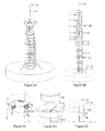
- the Figure 6A is a simplified perspective view illustrating such a type of turbomachine while it is being implemented. place and the Figure 6B represents this turbomachine while its active part 40 is raised relative to the holding structure 41.
- the turbomachine 40 comprises four turbine stages 1, 2, 3, 4 and a generator stage 5, the assembly being attached to a lower guide block 6.
- the turbomachine 40 includes side uprights 42 which are engageable in slotted leg members 44 of the holding structure.
- the holding structure 41 is directly attached to a foundation 43. It may be provided lateral reinforcements 45 to strengthen the structure.
- Each upright 44 of the holding structure preferably comprises an upper flare 47 to facilitate the introduction of the uprights 42 of the turbomachine.
- cables 15 mounted on reels of the guide block 6 are connected to the seat. This time, they pass inside the hollow amounts 44 of the holding structure to guide the insertion of the uprights 42 in the uprights 44.
- the Figure 6C represents a detail of the guide block. Cables 15 wound around the winches 23 extend laterally from the guide block into side posts 45 of this guide block forming part of the set of uprights 42 illustrated in FIG. Figure 6B .
- the Figure 6D represents an enlargement of the upper part of the holding structure 41. It is better to see an example of the flares 47 of the hollow uprights 44 in which the uprights 42 of the turbomachine proper and the guide cables 15 engage.
- a latch 48 equipped with a torsion spring. This latch is in the low position when the uprights 42 are engaged in the uprights 44 and automatically return to the position shown when these amounts 42 have exceeded the level of the latches. The cable 15 is thus guided at the upper part of the uprights 44.
- several latches 48 may be provided along a hollow upright 44.
- FIGS. 7A to 7F are schematic views illustrating the rise of a turbomachine column of the type of Figures 6A and 6B .
- FIGS. 8A and 8B are perspective views of another embodiment of a single-column turbomachine in which the turbomachine 50 is a turbomachine provided with a fairing 52 advantageously allowing it to orient itself automatically with respect to the direction of a current.
- the turbomachine is mounted on a central portion (not shown) of the guide block 6 free to rotate about a vertical axis relative to the seat 11.
- FIGS 9A and 9B represent an example in which the turbomachine 60 comprises two twin columns rotating in the opposite direction, of the type described in the application of French patent 07/58511 above.
- a guide block 6 comprising unrepresented winders or winches on which are mounted guide cables 15.
- a central pile 62 having substantially the height of the turbomachine and designed to strengthen its rigidity and improve its fixation.
- the turbomachine is mounted on a central portion (not shown) of the guide block 6 free to rotate about a vertical axis relative to the seat 11.
- FIGS 10A and 10B represent a structure similar to those of Figures 9A and 9B but in which the central pile 72 is extended substantially to the level of the surface of the medium in which the turbomachine is immersed. It will be understood that such a structure is suitable for environments in which the turbomachine is arranged in a shallow manner, and in which there are no particular navigation constraints above the turbomachines. The presence of such a pile going back to the surface simplifies in particular the handling of the various hoisting and power supply cables of the turbomachine. In addition, such a constitution makes it possible to lighten the structure, insofar as it is essentially the central pile which ensures the rigidity.
Landscapes
- Engineering & Computer Science (AREA)
- Chemical & Material Sciences (AREA)
- Combustion & Propulsion (AREA)
- Mechanical Engineering (AREA)
- General Engineering & Computer Science (AREA)
- Power Engineering (AREA)
- Life Sciences & Earth Sciences (AREA)
- General Life Sciences & Earth Sciences (AREA)
- Oceanography (AREA)
- Other Liquid Machine Or Engine Such As Wave Power Use (AREA)
- Hydraulic Turbines (AREA)
- Structures Of Non-Positive Displacement Pumps (AREA)
Claims (10)
- Hydraulikturbinenmotor, der zwischen einem Sitz (11) und einer Reihe von Turbinenstufen (1-4), die mit mindestens einem Generator (5) assoziiert sind, einen Führungsblock (6) aufweist, der entfernbar an der unteren Stufe des Turbinenmotors angebracht ist und an dem Sitz nestartig aufgenommen ist, wobei der Führungsblock Wickelvorrichtungen (23) für Führungskabel (15) enthält, deren Enden an dem Sitz befestigt sind.
- Turbinenmotor nach Anspruch 1, wobei die Wickelvorrichtungen motorisierte Winden sind.
- Turbinenmotor nach Anspruch 1 oder 2, wobei der Sitz (11) vertikale Spindeln (14) aufweist, in denen komplementäre Elemente (21) der Führungsblöcke (6) nestartig aufgenommen sind, wobei die Führungskabel (15) an den Spindeln angebracht sind.
- Turbinenmotor nach einem der Ansprüche 1 bis 3, der einen aktiven Teil (40) und eine Haltestruktur (41) aufweist, die an dem Sitz angebracht ist, wobei nur der aktive Teil entfernbar ist.
- Turbinenmotor nach Anspruch 4, wobei die Haltestruktur (41) vertikale Pfosten aufweist, welche die Form von geschlitzten Hülsen (44) haben, und wobei der aktive Teil (40) seitliche Pfosten (42) aufweist, die in die hülsenförmigen Pfosten eingeführt werden können, wobei die Führungskabel (15) durch einen unteren Teil der Pfosten des aktiven Teils der Maschine verlaufen und an dem Unterteil der hülsenförmigen Pfosten angebracht sind.
- Turbinenmotor nach Anspruch 5, wobei die hülsenförmigen Pfosten Verriegelungen (48) aufweisen, die sich schließen, wenn die seitlichen Pfosten (42) des aktiven Teils des Turbinenmotors aus den hülsenförmigen Pfosten (44) herausgezogen werden, um die Führungskabel in den Pfosten zu halten.
- Turbinenmotor nach einem der Ansprüche 1 bis 6, welcher zwei doppelte Säulen aufweist, wobei der Sitz einen mittleren Pfahl (62) aufweist, mit dem ein mittlerer Teil des Turbinenmotors in Eingriff kommt.
- Turbinenmotor nach Anspruch 7, wobei der Pfahl (72) zur Oberfläche des flüssigen Mediums hinaufragt, in welchem der Turbinenmotor eingetaucht ist.
- Verfahren zum Demontieren des Turbinenmotors nach einem der Ansprüche 1 bis 8 von einem Schiff aus, welches mit Hubmitteln (34) und mit Greifmitteln (36) versehen ist, welches folgende Schritte aufweist:Bringen des Schiffes (30) zum Einsatzort;Anheben des Turbinenmotors ausgehend von den Hubmitteln (34), die an einem oberen Teil des Turbinenmotors befestigt sind;sobald der obere Teil des Turbinenmotors das Niveau des Schiffes erreicht hat, Greifen des Führungsblockes (6) mit den Greifmitteln (36);Demontieren des Turbinenmotors Stufe um Stufe, während der Turbinenmotor stufenweise mittels der Greifmittel angehoben wird; undAbsenken des Führungsblocks, bis er mit den Spindeln des Sitzes (11) in Eingriff ist, zu dem er durch die Führungsmittel geleitet wird.
- Verfahren zum Montieren des Turbinenmotors nach einem der Ansprüche 1 bis 8 von einem Schiff aus, welches mit Hubmitteln (34) und mit Greifmitteln (36) versehen ist, welches folgende Schritte aufweist:Bringen des Schiffes (30) zum Einsatzort;Anheben des Führungsblockes (6) mit den Hubmitteln, die an einem oberen Teil des Führungsblockes befestigt sind;sobald der obere Teil des Führungsblocks (6) das Niveau des Schiffes erreicht hat, Greifen des Führungsblocks mit den Greifmitteln (36);Montieren des Turbinenmotors Stufe um Stufe, während der Turbinenmotor stufenweise mittels der Greifmittel abgesenkt wird; undAbsenken des Turbinenmotors mit den Hubmitteln, die an einem oberen Teil des Turbinenmotors befestigt sind, bis der Führungsblock mit den Spindeln des Sitzes (11) in Eingriff ist.
Applications Claiming Priority (2)
| Application Number | Priority Date | Filing Date | Title |
|---|---|---|---|
| FR0956120A FR2949826B1 (fr) | 2009-09-09 | 2009-09-09 | Turbomachine hydraulique a maintenance simple |
| PCT/FR2010/051883 WO2011030067A1 (fr) | 2009-09-09 | 2010-09-09 | Turbomachine hydraulique à maintenance simple |
Publications (2)
| Publication Number | Publication Date |
|---|---|
| EP2475871A1 EP2475871A1 (de) | 2012-07-18 |
| EP2475871B1 true EP2475871B1 (de) | 2015-01-21 |
Family
ID=42135935
Family Applications (1)
| Application Number | Title | Priority Date | Filing Date |
|---|---|---|---|
| EP10770544.4A Active EP2475871B1 (de) | 2009-09-09 | 2010-09-09 | Wartungsarmer hydraulischer turbinenmotor |
Country Status (12)
| Country | Link |
|---|---|
| US (1) | US20120189448A1 (de) |
| EP (1) | EP2475871B1 (de) |
| JP (1) | JP5723369B2 (de) |
| KR (1) | KR101702051B1 (de) |
| CN (1) | CN103038498A (de) |
| AU (1) | AU2010294017B2 (de) |
| BR (1) | BR112012005325A2 (de) |
| CA (1) | CA2773077C (de) |
| CL (1) | CL2012000605A1 (de) |
| FR (1) | FR2949826B1 (de) |
| NZ (1) | NZ598572A (de) |
| WO (1) | WO2011030067A1 (de) |
Families Citing this family (11)
| Publication number | Priority date | Publication date | Assignee | Title |
|---|---|---|---|---|
| FR2967216B1 (fr) * | 2010-11-05 | 2012-12-07 | Electricite De France | Hydrolienne a flux transverse a etages autonomes |
| FR2978502B1 (fr) * | 2011-07-25 | 2013-08-30 | Electricite De France | Turbine hydraulique a trainee en bout d'aile reduite |
| GB2513917B (en) * | 2013-05-10 | 2015-07-29 | 1847 Subsea Engineering Ltd | Tidal power generation apparatus and methods |
| GB201419099D0 (en) * | 2014-10-27 | 2014-12-10 | Repetitive Energy Company Ltd | Water Turbine |
| NO20160787A1 (en) | 2016-05-10 | 2017-06-19 | Norwegian Tidal Solutions | Underwater electrical power plant |
| GB2579196B (en) * | 2018-11-22 | 2021-10-06 | Cleantech Eng Ltd | Upright tidal turbine assembly |
| CN119452163A (zh) | 2022-04-12 | 2025-02-14 | 马克·丹尼尔·法博 | 用于操作流体涡轮机集群的系统和方法 |
| WO2024050317A1 (en) | 2022-08-28 | 2024-03-07 | Flower Turbines, Inc. | Systems and methods for operating a cluster of fluid turbines |
| CN119895139A (zh) | 2022-09-18 | 2025-04-25 | 花卉涡轮机股份有限公司 | 用于涡轮轴的套筒 |
| WO2024151908A2 (en) | 2023-01-15 | 2024-07-18 | Mark Daniel Farb | Systems and methods for fluid turbine operations |
| CN121311675A (zh) | 2023-04-09 | 2026-01-09 | 花卉涡轮机股份有限公司 | 流体涡轮机操作系统和方法 |
Family Cites Families (9)
| Publication number | Priority date | Publication date | Assignee | Title |
|---|---|---|---|---|
| FR450209A (fr) | 1912-10-31 | 1913-03-19 | Louis Emile Andre Gillier | Dispositif permettant de réaliser la vaporisation instantanée d'un fil, au moment de son emploi au tissage et la condensation de la vapeur employée |
| FR550420A (fr) | 1921-05-10 | 1923-03-09 | Raccord rigide pour soupapes de pneumatiques | |
| NL35277C (de) | 1932-07-15 | |||
| GB0227739D0 (en) * | 2002-11-28 | 2003-01-08 | Marine Current Turbines Ltd | Supporting structures for water current (including tidal stream) turbines |
| FR2865777B1 (fr) * | 2004-02-04 | 2006-05-05 | Inst Nat Polytech Grenoble | Turbomachine hydraulique |
| FR2882109B1 (fr) * | 2005-02-14 | 2010-09-03 | Inst Nat Polytech Grenoble | Dispositif de maintien d'une turbomachine hydraulique |
| GB2431628B (en) * | 2005-10-31 | 2009-01-28 | Tidal Generation Ltd | A deployment and retrieval apparatus for submerged power generating devices |
| GB0705476D0 (en) * | 2007-03-22 | 2007-05-02 | Marine Current Turbines Ltd | Deep water water current turbine installations |
| FR2922606B1 (fr) * | 2007-10-23 | 2014-07-04 | Inst Nat Polytech Grenoble | Turbomachine a turbines hydrauliques a flux transverse a force globale de portance reduite |
-
2009
- 2009-09-09 FR FR0956120A patent/FR2949826B1/fr not_active Expired - Fee Related
-
2010
- 2010-09-09 AU AU2010294017A patent/AU2010294017B2/en not_active Ceased
- 2010-09-09 KR KR1020127009173A patent/KR101702051B1/ko not_active Expired - Fee Related
- 2010-09-09 EP EP10770544.4A patent/EP2475871B1/de active Active
- 2010-09-09 JP JP2012528429A patent/JP5723369B2/ja not_active Expired - Fee Related
- 2010-09-09 WO PCT/FR2010/051883 patent/WO2011030067A1/fr not_active Ceased
- 2010-09-09 US US13/395,176 patent/US20120189448A1/en not_active Abandoned
- 2010-09-09 CA CA2773077A patent/CA2773077C/en active Active
- 2010-09-09 NZ NZ598572A patent/NZ598572A/xx not_active IP Right Cessation
- 2010-09-09 CN CN2010800403958A patent/CN103038498A/zh active Pending
- 2010-09-09 BR BR112012005325-6A patent/BR112012005325A2/pt not_active Application Discontinuation
-
2012
- 2012-03-07 CL CL2012000605A patent/CL2012000605A1/es unknown
Also Published As
| Publication number | Publication date |
|---|---|
| AU2010294017A1 (en) | 2012-04-12 |
| KR101702051B1 (ko) | 2017-02-02 |
| CL2012000605A1 (es) | 2012-09-07 |
| CA2773077A1 (en) | 2011-03-17 |
| JP5723369B2 (ja) | 2015-05-27 |
| CA2773077C (en) | 2019-05-28 |
| JP2013504709A (ja) | 2013-02-07 |
| US20120189448A1 (en) | 2012-07-26 |
| FR2949826A1 (fr) | 2011-03-11 |
| FR2949826B1 (fr) | 2012-01-20 |
| KR20120103568A (ko) | 2012-09-19 |
| NZ598572A (en) | 2013-02-22 |
| AU2010294017B2 (en) | 2015-11-26 |
| BR112012005325A2 (pt) | 2020-10-27 |
| EP2475871A1 (de) | 2012-07-18 |
| WO2011030067A1 (fr) | 2011-03-17 |
| CN103038498A (zh) | 2013-04-10 |
Similar Documents
| Publication | Publication Date | Title |
|---|---|---|
| EP2475871B1 (de) | Wartungsarmer hydraulischer turbinenmotor | |
| EP2041429B1 (de) | Vorrichtung und verfahren zur schnellen demontage des rotors und der gondel von einem windturbinenmast und mit einer solchen vorrichtung ausgestattete windturbine | |
| EP1581703B1 (de) | Verfahren zur offshore-montage einer windturbine | |
| EP2633214B1 (de) | Schiff mit einer brücke mit einer vertiefung mit eingebautem drehteller | |
| EP1716293A1 (de) | Konstruktion zum transportieren, installieren und demontieren der elemente einer festgelegten ölplattform und verfahren zur verwendung der konstruktion | |
| KR101790970B1 (ko) | 육상에서 조립한 해상풍력발전기의 해상에서의 설치방법 | |
| EP2647767A1 (de) | Off shore Gründung einer Windenergieanlage. | |
| EP2495162A1 (de) | Transportschiff einer Windkraftanlage an einen Offshore-Standort und Verfahren zu ihrer Aufstellung | |
| EP1773707A1 (de) | Hebeanordnung | |
| EP2058444B1 (de) | Konstruktionsverfahren eines Tiefbaus und entsprechendes System | |
| EP2516251B1 (de) | Pendelsystem für den transport einer hoch- und tiefbaustruktur in einem wassermedium | |
| EP4373735B1 (de) | Vorrichtung zum handhaben einer last zum installieren oder entfernen einer schaufel auf einer offshore-windturbine und verfahren zum einsetzen einer solchen vorrichtung | |
| EP4590578A1 (de) | Schwimmende tragstruktur mit mehreren zentralen säulen für eine offshore-windturbine und verfahren zur montage solch einer struktur | |
| EP4259927B1 (de) | Verfahren zur montage eines schwimmenden offshore-windparks | |
| EP0863260A1 (de) | Verfahren zum Verbinden der Beingurte einer Ölplattform | |
| CA1094400A (fr) | Dispositif de mise en tension des lignes d'ancrage | |
| FR2970748A1 (fr) | Procede pour la realisation d'operations de maintenance sur un dispositif d'eolienne flottante offshore et systeme correspondant | |
| EP3144213B1 (de) | Verfahren für den einbau eines länglichen grundelements einer windkraftanlage, insbesondere für den mast der windkraftanlage | |
| BE887882A (fr) | Structure pour supporter un appareillage au-dessus du fond d'une masse d'eau | |
| CN110402317B (zh) | 用于处理、储存和运输的系统和方法 | |
| FR3125504A1 (fr) | Procédé pour le montage ou le démontage d’une pale sur une éolienne en mer et plateforme équipée pour la mise en œuvre d’un tel procédé. | |
| FR3139331A1 (fr) | Procédé et système pour le montage d’une pale sur une éolienne en mer. | |
| WO2023052444A1 (fr) | Système et procédé de mise à l'eau d'une charge lourde |
Legal Events
| Date | Code | Title | Description |
|---|---|---|---|
| PUAI | Public reference made under article 153(3) epc to a published international application that has entered the european phase |
Free format text: ORIGINAL CODE: 0009012 |
|
| 17P | Request for examination filed |
Effective date: 20120305 |
|
| AK | Designated contracting states |
Kind code of ref document: A1 Designated state(s): AL AT BE BG CH CY CZ DE DK EE ES FI FR GB GR HR HU IE IS IT LI LT LU LV MC MK MT NL NO PL PT RO SE SI SK SM TR |
|
| DAX | Request for extension of the european patent (deleted) | ||
| REG | Reference to a national code |
Ref country code: DE Ref legal event code: R079 Ref document number: 602010021987 Country of ref document: DE Free format text: PREVIOUS MAIN CLASS: F03B0013260000 Ipc: F03B0017060000 |
|
| GRAP | Despatch of communication of intention to grant a patent |
Free format text: ORIGINAL CODE: EPIDOSNIGR1 |
|
| RIC1 | Information provided on ipc code assigned before grant |
Ipc: F03B 17/06 20060101AFI20140731BHEP Ipc: F03B 13/26 20060101ALI20140731BHEP |
|
| INTG | Intention to grant announced |
Effective date: 20140815 |
|
| GRAS | Grant fee paid |
Free format text: ORIGINAL CODE: EPIDOSNIGR3 |
|
| GRAA | (expected) grant |
Free format text: ORIGINAL CODE: 0009210 |
|
| AK | Designated contracting states |
Kind code of ref document: B1 Designated state(s): AL AT BE BG CH CY CZ DE DK EE ES FI FR GB GR HR HU IE IS IT LI LT LU LV MC MK MT NL NO PL PT RO SE SI SK SM TR |
|
| REG | Reference to a national code |
Ref country code: GB Ref legal event code: FG4D Free format text: NOT ENGLISH |
|
| REG | Reference to a national code |
Ref country code: CH Ref legal event code: EP |
|
| REG | Reference to a national code |
Ref country code: IE Ref legal event code: FG4D Free format text: LANGUAGE OF EP DOCUMENT: FRENCH |
|
| REG | Reference to a national code |
Ref country code: DE Ref legal event code: R096 Ref document number: 602010021987 Country of ref document: DE Effective date: 20150305 |
|
| REG | Reference to a national code |
Ref country code: AT Ref legal event code: REF Ref document number: 709318 Country of ref document: AT Kind code of ref document: T Effective date: 20150315 |
|
| REG | Reference to a national code |
Ref country code: NL Ref legal event code: VDEP Effective date: 20150121 |
|
| REG | Reference to a national code |
Ref country code: AT Ref legal event code: MK05 Ref document number: 709318 Country of ref document: AT Kind code of ref document: T Effective date: 20150121 |
|
| REG | Reference to a national code |
Ref country code: LT Ref legal event code: MG4D |
|
| PG25 | Lapsed in a contracting state [announced via postgrant information from national office to epo] |
Ref country code: NO Free format text: LAPSE BECAUSE OF FAILURE TO SUBMIT A TRANSLATION OF THE DESCRIPTION OR TO PAY THE FEE WITHIN THE PRESCRIBED TIME-LIMIT Effective date: 20150421 Ref country code: FI Free format text: LAPSE BECAUSE OF FAILURE TO SUBMIT A TRANSLATION OF THE DESCRIPTION OR TO PAY THE FEE WITHIN THE PRESCRIBED TIME-LIMIT Effective date: 20150121 Ref country code: ES Free format text: LAPSE BECAUSE OF FAILURE TO SUBMIT A TRANSLATION OF THE DESCRIPTION OR TO PAY THE FEE WITHIN THE PRESCRIBED TIME-LIMIT Effective date: 20150121 Ref country code: LT Free format text: LAPSE BECAUSE OF FAILURE TO SUBMIT A TRANSLATION OF THE DESCRIPTION OR TO PAY THE FEE WITHIN THE PRESCRIBED TIME-LIMIT Effective date: 20150121 Ref country code: HR Free format text: LAPSE BECAUSE OF FAILURE TO SUBMIT A TRANSLATION OF THE DESCRIPTION OR TO PAY THE FEE WITHIN THE PRESCRIBED TIME-LIMIT Effective date: 20150121 Ref country code: SE Free format text: LAPSE BECAUSE OF FAILURE TO SUBMIT A TRANSLATION OF THE DESCRIPTION OR TO PAY THE FEE WITHIN THE PRESCRIBED TIME-LIMIT Effective date: 20150121 Ref country code: BG Free format text: LAPSE BECAUSE OF FAILURE TO SUBMIT A TRANSLATION OF THE DESCRIPTION OR TO PAY THE FEE WITHIN THE PRESCRIBED TIME-LIMIT Effective date: 20150421 |
|
| PG25 | Lapsed in a contracting state [announced via postgrant information from national office to epo] |
Ref country code: LV Free format text: LAPSE BECAUSE OF FAILURE TO SUBMIT A TRANSLATION OF THE DESCRIPTION OR TO PAY THE FEE WITHIN THE PRESCRIBED TIME-LIMIT Effective date: 20150121 Ref country code: PL Free format text: LAPSE BECAUSE OF FAILURE TO SUBMIT A TRANSLATION OF THE DESCRIPTION OR TO PAY THE FEE WITHIN THE PRESCRIBED TIME-LIMIT Effective date: 20150121 Ref country code: NL Free format text: LAPSE BECAUSE OF FAILURE TO SUBMIT A TRANSLATION OF THE DESCRIPTION OR TO PAY THE FEE WITHIN THE PRESCRIBED TIME-LIMIT Effective date: 20150121 Ref country code: IS Free format text: LAPSE BECAUSE OF FAILURE TO SUBMIT A TRANSLATION OF THE DESCRIPTION OR TO PAY THE FEE WITHIN THE PRESCRIBED TIME-LIMIT Effective date: 20150521 Ref country code: GR Free format text: LAPSE BECAUSE OF FAILURE TO SUBMIT A TRANSLATION OF THE DESCRIPTION OR TO PAY THE FEE WITHIN THE PRESCRIBED TIME-LIMIT Effective date: 20150422 Ref country code: AT Free format text: LAPSE BECAUSE OF FAILURE TO SUBMIT A TRANSLATION OF THE DESCRIPTION OR TO PAY THE FEE WITHIN THE PRESCRIBED TIME-LIMIT Effective date: 20150121 |
|
| REG | Reference to a national code |
Ref country code: DE Ref legal event code: R097 Ref document number: 602010021987 Country of ref document: DE |
|
| PG25 | Lapsed in a contracting state [announced via postgrant information from national office to epo] |
Ref country code: RO Free format text: LAPSE BECAUSE OF FAILURE TO SUBMIT A TRANSLATION OF THE DESCRIPTION OR TO PAY THE FEE WITHIN THE PRESCRIBED TIME-LIMIT Effective date: 20150121 Ref country code: EE Free format text: LAPSE BECAUSE OF FAILURE TO SUBMIT A TRANSLATION OF THE DESCRIPTION OR TO PAY THE FEE WITHIN THE PRESCRIBED TIME-LIMIT Effective date: 20150121 Ref country code: CZ Free format text: LAPSE BECAUSE OF FAILURE TO SUBMIT A TRANSLATION OF THE DESCRIPTION OR TO PAY THE FEE WITHIN THE PRESCRIBED TIME-LIMIT Effective date: 20150121 Ref country code: DK Free format text: LAPSE BECAUSE OF FAILURE TO SUBMIT A TRANSLATION OF THE DESCRIPTION OR TO PAY THE FEE WITHIN THE PRESCRIBED TIME-LIMIT Effective date: 20150121 Ref country code: SK Free format text: LAPSE BECAUSE OF FAILURE TO SUBMIT A TRANSLATION OF THE DESCRIPTION OR TO PAY THE FEE WITHIN THE PRESCRIBED TIME-LIMIT Effective date: 20150121 |
|
| PLBE | No opposition filed within time limit |
Free format text: ORIGINAL CODE: 0009261 |
|
| STAA | Information on the status of an ep patent application or granted ep patent |
Free format text: STATUS: NO OPPOSITION FILED WITHIN TIME LIMIT |
|
| 26N | No opposition filed |
Effective date: 20151022 |
|
| PG25 | Lapsed in a contracting state [announced via postgrant information from national office to epo] |
Ref country code: IT Free format text: LAPSE BECAUSE OF FAILURE TO SUBMIT A TRANSLATION OF THE DESCRIPTION OR TO PAY THE FEE WITHIN THE PRESCRIBED TIME-LIMIT Effective date: 20150121 |
|
| PG25 | Lapsed in a contracting state [announced via postgrant information from national office to epo] |
Ref country code: SI Free format text: LAPSE BECAUSE OF FAILURE TO SUBMIT A TRANSLATION OF THE DESCRIPTION OR TO PAY THE FEE WITHIN THE PRESCRIBED TIME-LIMIT Effective date: 20150121 |
|
| PG25 | Lapsed in a contracting state [announced via postgrant information from national office to epo] |
Ref country code: LU Free format text: LAPSE BECAUSE OF FAILURE TO SUBMIT A TRANSLATION OF THE DESCRIPTION OR TO PAY THE FEE WITHIN THE PRESCRIBED TIME-LIMIT Effective date: 20150909 Ref country code: MC Free format text: LAPSE BECAUSE OF FAILURE TO SUBMIT A TRANSLATION OF THE DESCRIPTION OR TO PAY THE FEE WITHIN THE PRESCRIBED TIME-LIMIT Effective date: 20150121 |
|
| REG | Reference to a national code |
Ref country code: CH Ref legal event code: PL |
|
| PG25 | Lapsed in a contracting state [announced via postgrant information from national office to epo] |
Ref country code: CH Free format text: LAPSE BECAUSE OF NON-PAYMENT OF DUE FEES Effective date: 20150930 Ref country code: LI Free format text: LAPSE BECAUSE OF NON-PAYMENT OF DUE FEES Effective date: 20150930 |
|
| REG | Reference to a national code |
Ref country code: FR Ref legal event code: PLFP Year of fee payment: 7 |
|
| PG25 | Lapsed in a contracting state [announced via postgrant information from national office to epo] |
Ref country code: MT Free format text: LAPSE BECAUSE OF FAILURE TO SUBMIT A TRANSLATION OF THE DESCRIPTION OR TO PAY THE FEE WITHIN THE PRESCRIBED TIME-LIMIT Effective date: 20150121 |
|
| PG25 | Lapsed in a contracting state [announced via postgrant information from national office to epo] |
Ref country code: HU Free format text: LAPSE BECAUSE OF FAILURE TO SUBMIT A TRANSLATION OF THE DESCRIPTION OR TO PAY THE FEE WITHIN THE PRESCRIBED TIME-LIMIT; INVALID AB INITIO Effective date: 20100909 Ref country code: SM Free format text: LAPSE BECAUSE OF FAILURE TO SUBMIT A TRANSLATION OF THE DESCRIPTION OR TO PAY THE FEE WITHIN THE PRESCRIBED TIME-LIMIT Effective date: 20150121 |
|
| PG25 | Lapsed in a contracting state [announced via postgrant information from national office to epo] |
Ref country code: CY Free format text: LAPSE BECAUSE OF FAILURE TO SUBMIT A TRANSLATION OF THE DESCRIPTION OR TO PAY THE FEE WITHIN THE PRESCRIBED TIME-LIMIT Effective date: 20150121 |
|
| PG25 | Lapsed in a contracting state [announced via postgrant information from national office to epo] |
Ref country code: BE Free format text: LAPSE BECAUSE OF NON-PAYMENT OF DUE FEES Effective date: 20150930 |
|
| PG25 | Lapsed in a contracting state [announced via postgrant information from national office to epo] |
Ref country code: TR Free format text: LAPSE BECAUSE OF FAILURE TO SUBMIT A TRANSLATION OF THE DESCRIPTION OR TO PAY THE FEE WITHIN THE PRESCRIBED TIME-LIMIT Effective date: 20150121 |
|
| REG | Reference to a national code |
Ref country code: FR Ref legal event code: PLFP Year of fee payment: 8 |
|
| PG25 | Lapsed in a contracting state [announced via postgrant information from national office to epo] |
Ref country code: MK Free format text: LAPSE BECAUSE OF FAILURE TO SUBMIT A TRANSLATION OF THE DESCRIPTION OR TO PAY THE FEE WITHIN THE PRESCRIBED TIME-LIMIT Effective date: 20150121 Ref country code: PT Free format text: LAPSE BECAUSE OF FAILURE TO SUBMIT A TRANSLATION OF THE DESCRIPTION OR TO PAY THE FEE WITHIN THE PRESCRIBED TIME-LIMIT Effective date: 20150121 |
|
| REG | Reference to a national code |
Ref country code: FR Ref legal event code: PLFP Year of fee payment: 9 |
|
| PG25 | Lapsed in a contracting state [announced via postgrant information from national office to epo] |
Ref country code: AL Free format text: LAPSE BECAUSE OF FAILURE TO SUBMIT A TRANSLATION OF THE DESCRIPTION OR TO PAY THE FEE WITHIN THE PRESCRIBED TIME-LIMIT Effective date: 20150121 |
|
| PGFP | Annual fee paid to national office [announced via postgrant information from national office to epo] |
Ref country code: DE Payment date: 20190913 Year of fee payment: 10 |
|
| REG | Reference to a national code |
Ref country code: DE Ref legal event code: R119 Ref document number: 602010021987 Country of ref document: DE |
|
| PG25 | Lapsed in a contracting state [announced via postgrant information from national office to epo] |
Ref country code: DE Free format text: LAPSE BECAUSE OF NON-PAYMENT OF DUE FEES Effective date: 20210401 |
|
| PGFP | Annual fee paid to national office [announced via postgrant information from national office to epo] |
Ref country code: IE Payment date: 20230817 Year of fee payment: 14 |
|
| PG25 | Lapsed in a contracting state [announced via postgrant information from national office to epo] |
Ref country code: IE Free format text: LAPSE BECAUSE OF NON-PAYMENT OF DUE FEES Effective date: 20240909 |
|
| PGFP | Annual fee paid to national office [announced via postgrant information from national office to epo] |
Ref country code: GB Payment date: 20250919 Year of fee payment: 16 |
|
| PGFP | Annual fee paid to national office [announced via postgrant information from national office to epo] |
Ref country code: FR Payment date: 20250930 Year of fee payment: 16 |