EP2476094B1 - Verfahren zur installation einer fahrzeugüberwachungsvorrichtung - Google Patents
Verfahren zur installation einer fahrzeugüberwachungsvorrichtung Download PDFInfo
- Publication number
- EP2476094B1 EP2476094B1 EP10762998.2A EP10762998A EP2476094B1 EP 2476094 B1 EP2476094 B1 EP 2476094B1 EP 10762998 A EP10762998 A EP 10762998A EP 2476094 B1 EP2476094 B1 EP 2476094B1
- Authority
- EP
- European Patent Office
- Prior art keywords
- road
- value
- image
- vehicle monitoring
- vehicle
- Prior art date
- Legal status (The legal status is an assumption and is not a legal conclusion. Google has not performed a legal analysis and makes no representation as to the accuracy of the status listed.)
- Active
Links
Images



Classifications
-
- G—PHYSICS
- G08—SIGNALLING
- G08G—TRAFFIC CONTROL SYSTEMS
- G08G1/00—Traffic control systems for road vehicles
- G08G1/01—Detecting movement of traffic to be counted or controlled
- G08G1/052—Detecting movement of traffic to be counted or controlled with provision for determining speed or overspeed
-
- G—PHYSICS
- G06—COMPUTING OR CALCULATING; COUNTING
- G06T—IMAGE DATA PROCESSING OR GENERATION, IN GENERAL
- G06T7/00—Image analysis
- G06T7/80—Analysis of captured images to determine intrinsic or extrinsic camera parameters, i.e. camera calibration
-
- G—PHYSICS
- G08—SIGNALLING
- G08G—TRAFFIC CONTROL SYSTEMS
- G08G1/00—Traffic control systems for road vehicles
- G08G1/01—Detecting movement of traffic to be counted or controlled
- G08G1/04—Detecting movement of traffic to be counted or controlled using optical or ultrasonic detectors
-
- G—PHYSICS
- G06—COMPUTING OR CALCULATING; COUNTING
- G06T—IMAGE DATA PROCESSING OR GENERATION, IN GENERAL
- G06T2207/00—Indexing scheme for image analysis or image enhancement
- G06T2207/30—Subject of image; Context of image processing
- G06T2207/30236—Traffic on road, railway or crossing
Definitions
- the present invention relates to a method of installing a vehicle control apparatus traveling on a road. It also relates to a program and a vehicle control assembly for implementing the method.
- the invention can be applied to a device for controlling the speeds of vehicles traveling on the road.
- a vehicle speed control apparatus comprises a speed measuring system which is coupled to a photographic system.
- the apparatus is intended to be disposed on a road approach, being oriented towards a vehicle whose speed must be controlled.
- the speed measurement system is commonly called radar, and is based on the Doppler effect.
- the principle of such a measure is well known, so there is no need to explain it again. It is only recalled that the measurement of the speed of the vehicle is based on the radial component of this speed which is parallel to the direction which connects the vehicle to the speed measuring system at the time of the measurement.
- the transverse component of the vehicle speed which is perpendicular to the vehicle-to-system direction of measurement, does not interfere with the Doppler effect.
- the result of the speed measurement therefore critically depends on the value of the angle which separates the direction of movement of the vehicle and the direction vehicle-system of measurement. For this reason, it is essential to accurately determine the value of this angle before a speed measurement is performed.
- Regulations fix this accuracy, for example within ⁇ 0.5 ° (degree), or within ⁇ 0.65% depending on the origin of the regulation being applied.
- the supplier of the speed measuring system can recommend a value for the angle between the direction of movement of the vehicle and the vehicle-system direction of measurement, for example about 25 °.
- the photographic system produces one or more image (s) of the vehicle whose speed is controlled. This or these image (s) allows (tent) to identify the vehicle, including the number of its license plate.
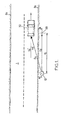
- the speed control performance by-law may require that proof be provided showing that angle ⁇ 11 has been duly determined and adjusted for the control session.
- photographs are taken of the operator setting milestone 20, which show the measurement of distances d 1 and d 2 . These photos must then be accessible from the control file of each vehicle whose speed is excessive.
- this procedure of validity of the road check is also tedious itself.
- the angular measurement deflection is deduced from a measurement of the optical viewing angle, this measurement being made from an image that is captured by the photographic system of the device.
- No distance measurement or operator movement along the road is therefore necessary, so that the installation of the device for a new roadside control session is greatly simplified.
- no milestone is to be placed at a setback distance which must be accurately measured from the edge of the road.
- the installation of the vehicle control device is therefore much faster, and can be performed by a small number of operators.
- Such a method is particularly suitable for a vehicle control device which is of the mobile road control device type, since the angular deviation of measurement is different in this case at each new roadside control session.
- the image from which the value of the optical viewing angle is deduced can be kept very simply in the file of each vehicle controlled.
- the creepage distances and the point (s) of flight that were used to determine this angle of sight can then be checked at any time later, particularly during the administrative or legal processing of the file.
- creepage distances can be determined in multiple ways in the image (s) that are (are) captured.
- the two opposite edges of the road, the two edge lines of the road if they are marked on its surface, and / or the central marking line of the road may be used to determine the vanishing lines of each captured image.
- the direction of each road edge, each shore line or the central marking line may in particular be determined by superimposing, in the image that has been captured, a rectilinear segment at this road edge, this line of bank or the central marking line.
- Such a superposition is carried out globally, in a medium way, so that it is not hindered by local irregularities of the roadside or the corresponding marking line.
- the direction of each roadside or marking line in the image can thus be determined accurately.
- the vanishing point As a result, as well as the optical viewing angle and hence the radio angle of view, are also determined with greater accuracy.
- Such a method which is based on image processing can be executed automatically, in particular by a computer processing unit, in a way that is quick and simple for the operator in charge of the roadside check.
- the vehicle control device may be of the type of speed control device of vehicles traveling on the road.
- the measurement system may comprise a Doppler speed measurement system. A radioelectic axis of this Doppler velocity measuring system then forms the radial direction of distance measurement.
- the invention also proposes a computer program, which is intended to be stored in a memory of a computer processing unit, on a removable memory medium or on a computer reading medium, and which includes instructions for executing the instructions. steps / 5 / to / 7 / of a method according to the invention, as described above.
- a program must be considered as a product within the framework of the protection sought by this patent application,
- the invention also proposes a vehicle control assembly, which comprises the vehicle control apparatus and a computer processing unit, the latter comprising a memory or a computer reading medium adapted to store the instructions of the program. previous computer.
- the invention is now described in detail in the particular case of a vehicle speed control apparatus. However, it is understood that it may be applied to other types of roadside control devices, such as separation distance control devices between two vehicles, or aircraft number plate reading devices. vehicles.
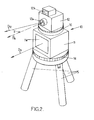
- a vehicle speed control apparatus which is generally designated by the reference numeral 10 comprises a Doppler effect speed measuring system 11 and a photographic system 12.
- the systems 11 and 12 may be superimposed with a relative orientation which is fixed initially. They are mounted together on a support that can be a base when it is a fixed road control device, or a tripod 15 when it is a mobile device road control.
- the apparatus 10 may further comprise a rotation plate 14, which is arranged between its support on the one hand and the systems 11 and 12 on the other hand. The plate 14 makes it possible to turn the systems 11 and 12 together about a vertical axis, to modify an angular orientation of these located in a horizontal plane. It can be motorized or manually operated.
- the speed measuring system 11 by Doppler effect, or radar, has a transmission-reception window 11a, which is traversed by the radiation used to perform the speed measurement.
- D 11 denotes the radio axis of the radar 11, which constitutes the radial direction of distance measurement.
- the radar 11 measures the component of the speed of movement of a vehicle which is parallel to the radio axis D 11 , also called the radial component of the speed. The component of this speed which is perpendicular to the radio axis D 11 is not measured.
- the radio axis D 11 is fixed relative to the housing of the radar 11, when this housing is turned in any way.
- the radar 11 may be adapted to measure the speed of a vehicle moving away from or approaching the apparatus 10. In addition, the operation of the radar 11 is triggered automatically when a vehicle passing in front of the aircraft 10 is detected.
- the photographic system 12 may be a standard camera which includes a lens 12a and an illumination device 12b.
- the device 12b may be a flash, or any other illumination device, especially with continuous illumination.
- D 12 denotes the optical axis of the photographic system 12. More precisely, D 12 is the optical axis of the lens 12a, which generally passes through a geometric center of each image that is captured by the system 12.
- the axis optical D 12 is fixed relative to a housing of the system 12, whatever the movements that are applied to the latter housing.
- the operation of the photographic system 12 is synchronized with that of the radar 11.
- the radio axis D 11 of the radar 11 and the optical axis D 12 of the photographic system 12 are fixed with respect to one another during a period of use of the apparatus 10. They form an angle of mounting which is noted ⁇ , and which is a measure of the lack of parallelism between the axes D 11 and D 12 in a horizontal plane.
- the parallelism of the axes D 11 and D 12 is adjusted at the factory during the assembly of the apparatus 10, and the mounting angle ⁇ is measured initially and then periodically during maintenance sessions of the apparatus 10.
- a intermediate platen rotation 16 can be arranged between the systems 11 and 12 of the apparatus 10, to allow easier adjustment of the parallelism of the axes D 11 and D 12 .
- the skilled person knows several methods for measuring the mounting angle ⁇ . Throughout the present description of the invention, the value of the mounting angle ⁇ is fixed and assumed to have been determined according to one of these methods.
- the photographic system 12 produces an imaging relationship that associates any point within an input field of this photographic system with a point in each image that is captured by the same system.
- this imaging relationship constitutes a projection of the portion of space that is located in front of the photographic system 12, within its field of entry, in the plane of the image that is formed by the objective 12a and which is seized.
- the point Q is called the intermediate point.
- the point A is taken as the origin of the x and z axes in the image plane 12c.
- R is the image of the point P which is formed by the photographic system 12, with its coordinates x R and z R which are measured in the image plane 12c respectively along the x and z axes.
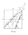
- the figure 3b represents the image plane 12c with two dotted lines: a rectilinear square pattern and a curved line pattern which corresponds to the previous one when the distortion of the photographic system 12 is applied.
- the curved field is obtained by applying the relations 2a and 2b to the points of the rectilinear frame.
- the points Q and R which are indicated respectively belong to the rectilinear frame and to the curved frame.
- the imaging relationship can be characterized from at least one image of a calibration pattern, which is captured by the photographic system 12.
- the coordinates x R and z R of the image point R can also be read or interpolated from a registered lookup table whose inputs can be the coordinates Q and Q Q of the intermediate point Q.
- the imaging relation can be characterized by equations that directly express the coordinates x R and z R of the image point R, in the image plane 12c, as a function of the X P , Y P and Z P coordinates of the point P of the input field.
- the characterization of the imaging relation of the photographic system 12 can be carried out in a production plant or in a technical maintenance center of the recording equipment. speed 10.
- the invention is based on the identification of creepage distances in an image that is captured after the speed control apparatus 10 has been installed on an approach to Route 1.
- These vanishing lines correspond to lines that are rectilinear and parallel in the actual scene that was photographed. At least two vanishing lines are thus identified.
- several groups of trailing lines are identified, each corresponding to lines in the photographed scene that are actually straight and parallel to one another within the same group, but which are oriented differently from a group to the other. other.
- each set of vanishing lines may include more than one two lines.
- the vanishing lines are generally curved, because of the optical distortions of the system 12, even though the lines to which they correspond in the photographed scene are rectilinear.
- curves that are curved lines of lines can be superimposed respectively on the images of the edges B 2 and B 3 of a straight segment of the road 1, and the image of the central marking line B 1
- These creepage distances must have regular curvatures, or regular curvature variations, to converge to a single vanishing point that can be accurately determined.
- the creepage distances are identified in the image after the image has been processed to suppress optical distortion of the photographic system 12.
- Lines that are straight in the actual photographed scene are then reproduced in lines that are also straight in the image that was captured and then corrected for optical distortion. It is then easier to precisely superimpose straight lines of vanishing lines to lines or elements of the image, even if these lines or elements of the image are interrupted, partially masked or irregular.
- the rectilinear creepage plot can be superimposed on an average position of a pattern line that is marked in the image, with a precision that is good.
- Images that are used to identify creepage distances can be captured at the beginning of the roadside check before a particular vehicle is checked.
- the vanishing lines can be located directly in an image that is captured during the control of a vehicle.
- each R point of one of these images has been moved to the position of the intermediate point Q such that the QR vector corresponds to the optical distortion, as illustrated by the figure 3b .
- the position of the intermediate point Q can be determined by numerically reversing the relations 2a and 2b which have been given above, to obtain the coordinates x Q and z Q as a function of the coordinates x R and z R.
- the vanishing lines that appear in all these corrected images of the optical distortion are therefore rectilinear.
- the use of the creepage L 1 and L 6 to L 9 makes it possible to avoid any increase or narrowing of the width of the road 1, in the segment of the road where the road check is carried out , does not distort the determination of the orientation of the apparatus 10 relative to the direction D 0 'of movement of the vehicles.
- a vanishing point F is then determined at the intersection of the vanishing lines that correspond to parallel lines in the scene that is photographed.
- This vanishing point F is characterized by its coordinates on the x and z axes, measured from the central point A.
- each vanishing point F which is thus determined in one of the images captured is not necessarily located within the peripheral boundaries of this image. Indeed, the image limit is fixed by a field diaphragm of the photographic system 12, or by the size of the photodetector matrix which is located in the image plane 12c, without relation to the scene being photographed.
- several vanishing points can be determined in the same image, one for each group of vanishing lines that have been identified in this image.
- the value of the optical viewing angle ⁇ 12 can be deduced from the coordinates of each vanishing point F in the corrected image of the optical distortions.
- the optical viewing angle ⁇ 12 is equal to the Arctan complementary value (x F / f) when the vanishing point is from a group of vanishing lines corresponding to a direction in the photographed scene that is perpendicular to route 1 ( figure 4c ).
- the dimension of the vanishing point F, along the z axis, depends on the inclination of the control apparatus 10 with respect to a horizontal plane, and on a possible slope of the road 1.
- ⁇ 11 ⁇ 12 + ⁇ when the mounting angle ⁇ is counted from the optical axis D 12 of the photographic system 12 to the radio axis D 11 of the radar 11, the latter forming the radial direction of distance measurement.
- the target value ⁇ 11 -target can be provided by the manufacturer of the tester 10.
- the vehicle control device 10 can then be rotated to reduce the error ⁇ , for example by actuating the rotation stage 14.
- the speed of the vehicle 30 traveling on the road 1 can then be measured using the radar 11.
- the value of the angular deviation of measurement ⁇ 11 is transmitted to the speed measuring system 11 in a known manner, which can be automated.
- a vehicle control assembly may comprise a control apparatus as described hitherto, and a computer processing unit which includes a memory or a computer reading medium adapted to store instructions of a program of computer.
- This program includes, in particular, instructions for determining at least one vanishing point in an image that has been captured, from several creepage distances that are identified in this image, and then to calculate the optical viewing angle ⁇ 12 and the deflection angular measurement ⁇ 11 .
- the entry of the characterizations of the creepage distances can be carried out in a precise and user-friendly way when the image is displayed on a screen.
- the program may then include sequences to assist the operator in identifying the creepage distances within the captured image. For example, a trailing-line plot can be superimposed on the image, which the operator can modify, move and orient differently in the image to bring it into coincidence with elements reproduced in the image, which he chooses. It then validates the plot that coincides with these selected picture elements and can restart the operation for another line of flight.
- the program may be adapted to perform image recognition with pattern recognition, and autonomously determine creepage distances and vanishing points.
- the program can perform itself the comparison of images and determine the creepage distances from the successive positions of the vehicle in the captured images.
- the vehicle control assembly may furthermore comprise an alarm system which is connected to be activated by the computer processing unit during execution of the program instructions, if the error ⁇ is greater than the fixed error value.
- the vehicle control assembly may further comprise a control system of the plate 14, which is adapted to control a rotation of this plate according to the error ⁇ .
- the imaging relationship can be characterized in multiple ways, which are equivalent in order to suppress the optical distortion of the photographic system that is used.
- the vanishing points in the image that is captured can also be identified in different ways, which are also equivalent to each other.
- the invention is not limited to a control of vehicle speeds, but that it can be applied to any road control device, for which the angle between the road and the radial direction of measurement remote needs to be determined.
Landscapes
- Physics & Mathematics (AREA)
- General Physics & Mathematics (AREA)
- Engineering & Computer Science (AREA)
- Computer Vision & Pattern Recognition (AREA)
- Theoretical Computer Science (AREA)
- Traffic Control Systems (AREA)
Claims (20)
- Verfahren zur Aufstellung eines Geräts zur Überwachung von Fahrzeugen (30), die auf einer Straße (1) fahren, wobei das Fahrzeugüberwachungsgerät (10) ein Messsystem (11) und ein fotografisches System (12) enthält, die miteinander verbunden sind, wobei das Verfahren die folgenden vorhergehenden Schritte enthält:/1/Charakterisieren einer Abbildungsbeziehung, die einen Punkt (R) in jedem vom fotografischen System (12) erfassten Bild jedem Punkt (P) zuordnet, der sich innerhalb eines Eingangsfelds des fotografischen Systems befindet, und/2/Bestimmen eines Werts eines Montagewinkels (ε) des Fahrzeugüberwachungsgeräts (10) zwischen einer optischen Achse (D12) des fotografischen Systems (12) und einer radialen Fernmessrichtung (D11) des Messsystems (11),
wobei das Verfahren außerdem die folgenden Schritte enthält:/3/Anordnen des Fahrzeugüberwachungsgeräts (10) an einem Rand (B2) der Straße (1),/4/bestimmten mindestens eines Bilds der Straße mit dem fotografischen System (12) des Fahrzeugüberwachungsgeräts (10),/5/ Festlegen mindestens eines Fluchtpunkts (F) in dem im Schritt /4/ / erfassten Bild ausgehend von mindestens zwei im Bild ermittelten Fluchtlinien (L1-L9),/6/Bestimmen eines Werts eines optischen Sichtwinkels (α12) zwischen der Straße (1) und der optischen Achse (D12) des fotografischen Systems (12) ausgehend von mindestens einer Koordinate jedes im Schritt /5/ bestimmten Fluchtpunkts (F) und der im Schritt /1/ charakterisierten Abbildungsbeziehung, und/7/ Bestimmen eines Werts einer Messwinkelabweichung (α11) zwischen der Straße (1) und der radialen Fernmessrichtung (D11) des Messsystems (11) ausgehend von dem im Schritt /6/ bestimmten Wert des optischen Sichtwinkels (α12) und von dem im Schritt /2/ bestimmten Wert des Montagewinkels (ε). - Verfahren nach Anspruch 1, wobei der Schritt /1/ die folgenden Teilschritte enthält:/1-1/Bestimmen eines zentralen Punkts (A) jedes Bilds entsprechend der optischen Achse (D12) des fotografischen Systems (12);/1-2/Charakterisieren einer zentralen Projektionsbeziehung, die Koordinaten des im Inneren des Eingangsfelds des fotografischen Systems (12) befindlichen Punkts (P) mit Koordinaten eines Zwischenpunkts (Q) in jedem erfassten Bild verbindet, wobei die zentrale Projektion einen beliebigen Punkt der optischen Achse (D12) des fotografischen Systems (12) dem im Teilschritt /1-1/ bestimmten zentralen Punkt (A) zuordnet; und/1-3/Charakterisieren einer optischen Verzerrung des fotografischen Systems (12) derart, dass die im Schritt /1/ charakterisierte Abbildungsbeziehung aus der im Teilschritt /1-2/ charakterisierten zentralen Projektion resultiert, gefolgt von einer Anwendung der optischen Verzerrung.
- Verfahren nach Anspruch 1 oder 2, das außerdem enthält:/8/ Berechnen eines Fehlers zwischen dem im Schritt /7/ bestimmten Wert der Messwinkelabweichung (α11) und einem. Zielwert für die Messwinkelabweichung; und/9/gegebenenfalls Erzeugen eines Alarmsignals, wenn der Fehler über einem festgelegten Fehlerwert liegt.
- Verfahren nach Anspruch 3, das außerdem enthält:/10/ Drehen des Fahrzeugüberwachungsgeräts (10), um den Fehler zwischen dem Wert der Messwinkelabweichung (α11) und dem Zielwert für die Messwinkelabweichung zu verringern.
- Verfahren nach einem der vorhergehenden Ansprüche, das außerdem einen Messschritt enthält, der für ein auf der Straße (1) fahrendes Fahrzeug (30) durchgeführt wird, wobei der Wert der im Schritt /7/ bestimmten Messwinkelabweichung (α11) verwendet wird, um ein Messergebnis für das Fahrzeug zu erhalten.
- Verfahren nach einem der vorhergehenden Ansprüche, wobei die vorhergehenden Schritte /1/ und /2/ in einer Produktionsfabrik oder in einem technischen Wartungszentrum des Fahrzeugüberwachungsgeräts (10) durchgeführt werden.
- Verfahren nach Anspruch 6, wobei die Abbildungsbeziehung im Schritt /1/ ausgehend von mindestens einem Bild eines Eichrasters charakterisiert wird, wobei das Bild vom fotografischen System (12) des Fahrzeugüberwachungsgeräts (10) erfasst wird.
- Verfahren nach einem der vorhergehenden Ansprüche, wobei das Fahrzeugüberwachungsgerät (10) von der Art mobiles Straßenüberwachungsgerät ist.
- Verfahren nach einem der vorhergehenden Ansprüche, wobei mindestens eine im Schritt /5/ ermittelte Fluchtlinie (L1-L3) im erfassten Bild einem geradlinigen Segment einer Mittelleitlinie (B1), einem Rand (B2, B3) oder einer Fahrbahnrandlinie der Straße (1) entspricht.
- Verfahren nach einem der vorergehenden Ansprüche, wobei mindestens eine im Schritt /5/ ermittelte Fluchtlinie (L4, L5) durch zwei Messstangen (C1-C4) ermittelt wird, die an einem Rand eines geradlinigen Segments der Straße (1) angeordnet sind.
- Verfahren nach einem der vorhergehenden Ansprüche, wobei mindestens eine im Schritt /5/ ermittelte Fluchtlinie (L6, L7) ausgehend von Punkten (D1-D4) im erfassten Bild ermittelt wird, die zwei Scheinwerfern eines auf der Straße (1) fahrenden Fahrzeugs (30, 40) entsprechen.
- Verfahren nach einem der vorhergehenden Ansprüche, wobei mindestens eine im Schritt /5/ ermittelte Fluchtlinie (L8, L9) ausgehend von Stellungen des gleichen Richtpunkts (E1, E2) eines auf der Straße (1) fahrenden Fahrzeugs (50) in unterschiedlichen Bildern festgelegt wird, die nacheinander ohne Bewegung des Fahrzeugüberwachungsgeräts (10) bestimmt werden, wobei die Stellungen in das gleiche der Bilder übertragen werden.
- Verfahren nach einem der vorhergehenden Ansprüche, wobei das Fahrzeugüberwachungsgerät (10) von der Art Geschwindigkeitsüberwachungsgerät der auf der Straße (1) fahrenden Fahrzeuge (30) ist, wobei das Messsystem (11) ein System der Geschwindigkeitsmessung durch Doppler-Effekt enthält, und eine Funkachse des Systems zur Geschwindigkeitsmessung durch Doppler-Effekt die radiale Fernmessrichtung (D11) formt.
- Computerprogrammprodukt, das dazu bestimmt ist, in einem Speicher einer Datenverarbeitungseinheit, in einem entfernbaren Speichermedium oder in einem Datenlesemedium gespeichert zu werden, dadurch gekennzeichnet, dass es Anweisungen aufweist, um die Schritte /5/ bis /7/ eines Verfahrens nach einem der vorhergehenden Ansprüche auszuführen.
- Computerprogrammprodukt nach Anspruch 14, dadurch gekennzeichnet, dass es außerdem Anweisungen aufweist, um:- eine Charakterisierung der Abbildungsbeziehung zu speichern;- den Wert des Montagewinkels (ε) des Fahrzeugüberwachungsgeräts (10) zwischen der optischen Achse (D12) des fotografischen Systems (12) und der radialen Fernmessrichtung (D11) des Messsystems (11) zu speichern; und- am Eingang Charakterisierungen von mindestens zwei Fluchtlinien (L1-L9) in mindestens einem erfassten Bild zu empfangen.
- Computerprogrammprodukt nach Anspruch 14 oder 15, dadurch gekennzeichnet, dass es außerdem Anweisungen zur Berechnung eines Fehlers zwischen dem Wert der Messwinkelabweichung (α11) und einem Zielwert für die Messwinkelabweichung aufweist.
- Fahrzeugüberwachungseznheit, die ein Fahrzeugüberwachungsgerät (10) enthält, das selbst ein Messsystem (11) und ein fotografisches System (12) enthält, die fest miteinander verbunden sind, wobei die Einheit dadurch gekennzeichnet ist, dass sie außerdem enthält:- eine Datenverarbeitungseinheit, die einen Speicher oder ein Datenlesemedium aufweist, der/das geeignet ist, um die Anweisungen eines Computerprogrammprodukts nach einem der Ansprüche 14 bis 16 zur speichern.
- Fahrzeugüberwachungseinheit nach Anspruch 17, die außerdem ein Alarmsystem enthält, das verbunden ist, um von der Datenverarbeitungseinheit bei einer Ausführung der Anweisungen des Computerprogrammprodukts aktiviert zu werden, wenn ein Fehler zwischen dem Wert der Messwinkelabweichung (α11) und einem Zielwert für die Messwinkelabweichung höher als ein festgelegter Fehlerwert ist.
- Fahrzeugüberwachungseinheit nach Anspruch 17 oder 18, die außerdem enthält:- eine Drehplatte (14), die zwischen einem Träger (15) des Fahrzeugüberwachungsgeräts (10) und dem Fahrzeugüberwachungsgerät angeordnet ist; und- ein Steuersystem der Platte, das geeignet ist, um eine Drehung der Platte abhängig von einem Fehler zwischen dem Wert der von der Datenverarbeitungseinheit erzeugten Messwinkelabweichung (α11) und einem Zielwert für die Messwinkelabweichung zu steuern.
- Fahrzeugüberwachungseinheit nach einem der Ansprüche 17 bis 19, wobei das Fahrzeugüberwachungsgerät von der Art Geschwindigkeitsüberwachungsgerät für die auf einer Straße (1) fahrenden Fahrzeuge (30) ist, wobei das Messsystem (11) ein System zur Geschwindigkeitsmessung durch Doppler-Effekt enthält, und eine Funkachse des Systems zur Geschwindigkeitsmessung durch Doppler-Effekt die radiale Fernmessrichtung (D11) formt.
Applications Claiming Priority (2)
| Application Number | Priority Date | Filing Date | Title |
|---|---|---|---|
| FR0956191A FR2949896B1 (fr) | 2009-09-10 | 2009-09-10 | Procede d'installation d'un appareil de controle de vehicules |
| PCT/FR2010/051759 WO2011030034A1 (fr) | 2009-09-10 | 2010-08-23 | Procede d'installation d'un appareil de controle de vehicules |
Publications (2)
| Publication Number | Publication Date |
|---|---|
| EP2476094A1 EP2476094A1 (de) | 2012-07-18 |
| EP2476094B1 true EP2476094B1 (de) | 2014-03-05 |
Family
ID=41463122
Family Applications (1)
| Application Number | Title | Priority Date | Filing Date |
|---|---|---|---|
| EP10762998.2A Active EP2476094B1 (de) | 2009-09-10 | 2010-08-23 | Verfahren zur installation einer fahrzeugüberwachungsvorrichtung |
Country Status (3)
| Country | Link |
|---|---|
| EP (1) | EP2476094B1 (de) |
| FR (1) | FR2949896B1 (de) |
| WO (1) | WO2011030034A1 (de) |
Families Citing this family (4)
| Publication number | Priority date | Publication date | Assignee | Title |
|---|---|---|---|---|
| DE102011050660B4 (de) * | 2011-05-26 | 2013-01-03 | Jenoptik Robot Gmbh | Verfahren zur Ausrichtung und Verfahren zur Kontrolle der Ausrichtung eines Verkehrsüberwachungsgerätes zu einem Fahrbahnrand |
| FR2989470B1 (fr) * | 2012-04-16 | 2014-05-16 | Morpho | Procede d'installation d'un cinemometre |
| FR2993672B1 (fr) * | 2012-07-20 | 2016-12-09 | Morpho | Procede d'installation d'un cinemometre sur une route en virage |
| FR3131777B1 (fr) * | 2022-01-13 | 2024-11-29 | Idemia Identity & Security France | procédé d’alignement d’une caméra sur une route |
Family Cites Families (1)
| Publication number | Priority date | Publication date | Assignee | Title |
|---|---|---|---|---|
| CH466385A (de) * | 1968-02-28 | 1968-12-15 | Zellweger Uster Ag | Verfahren und Vorrichtung zur Auswertung von Lichtbildern bei der Dopplerradar-Geschwindigkeitsmessung |
-
2009
- 2009-09-10 FR FR0956191A patent/FR2949896B1/fr not_active Expired - Fee Related
-
2010
- 2010-08-23 EP EP10762998.2A patent/EP2476094B1/de active Active
- 2010-08-23 WO PCT/FR2010/051759 patent/WO2011030034A1/fr not_active Ceased
Also Published As
| Publication number | Publication date |
|---|---|
| FR2949896B1 (fr) | 2011-11-18 |
| EP2476094A1 (de) | 2012-07-18 |
| WO2011030034A1 (fr) | 2011-03-17 |
| FR2949896A1 (fr) | 2011-03-11 |
Similar Documents
| Publication | Publication Date | Title |
|---|---|---|
| CN112219226A (zh) | 多阶段相机校准 | |
| WO2019025035A1 (en) | METHOD, APPARATUS AND COMPUTER PROGRAM FOR VEHICLE | |
| US11637967B2 (en) | Information processing apparatus, information processing method, and calibration apparatus | |
| EP2924671A1 (de) | Automatisches klassifizierungssystem von kraftfahrzeugen | |
| US11908165B2 (en) | Systems and methods for calibrating image capturing models | |
| EP2476094B1 (de) | Verfahren zur installation einer fahrzeugüberwachungsvorrichtung | |
| CN111480057B (zh) | 图像处理装置、图像处理方法和程序 | |
| EP3355277A1 (de) | Anzeigeverfahren mindestens einer darstellung eines objekts auf einem bildschirm, entsprechendes computerprogramm, entsprechendes elektronisches anzeige-gerät und -vorrichtung | |
| FR2973896A1 (fr) | Procede de guidage d'un avion vers un objet-cible predefini et systeme de guidage | |
| EP2161677A1 (de) | Erfassungsverfahren eines Zielobjekts für ein Kraftfahrzeug | |
| FR3043824A3 (fr) | Procede et dispositif d'etalonnage de parametres extrinseques d'une camera pour habitacle de vehicule automobile | |
| EP4212825B1 (de) | Verfahren zur ausrichtung einer kamera auf einer strasse | |
| CN208434047U (zh) | 一种用于消除眼镜镜面反光的摄像装置 | |
| CN106991415A (zh) | 用于车载鱼眼相机的图像处理方法和装置 | |
| JP2009059260A (ja) | 立体物識別装置および立体物識別方法 | |
| EP3018625B1 (de) | Kalibrierungsverfahren eines zielsystems | |
| US9232132B1 (en) | Light field image processing | |
| WO2021156026A1 (fr) | Procédé de calibration des caractéristiques extrinsèques d'un lidar | |
| CN107872615B (zh) | 全景扫描监控系统 | |
| CN106303395B (zh) | 一种实时双目偏振消光探测装置 | |
| FR3167467A1 (fr) | Procédé et dispositif d’apprentissage d’un modèle de prédiction de profondeur capable de traiter des objets dynamiques présents dans une scène. | |
| FR3167233A1 (fr) | Procédé et dispositif d’apprentissage d’un modèle de prédiction de positions de points tridimensionnels associé à un système de vision. | |
| FR3167468A1 (fr) | Procédé et dispositif d’apprentissage d’un modèle de prédiction de profondeur assisté par un modèle de flux de scène. | |
| FR3162894A1 (fr) | Procédé et dispositif de détermination d’une profondeur par un système de vision monoscopique appris par supervision d’un système de vision stéréoscopique | |
| FR3162893A1 (fr) | Procédé et dispositif d’apprentissage d’un modèle de prédiction de profondeur associé à un système de vision multi résolution |
Legal Events
| Date | Code | Title | Description |
|---|---|---|---|
| PUAI | Public reference made under article 153(3) epc to a published international application that has entered the european phase |
Free format text: ORIGINAL CODE: 0009012 |
|
| 17P | Request for examination filed |
Effective date: 20120301 |
|
| AK | Designated contracting states |
Kind code of ref document: A1 Designated state(s): AL AT BE BG CH CY CZ DE DK EE ES FI FR GB GR HR HU IE IS IT LI LT LU LV MC MK MT NL NO PL PT RO SE SI SK SM TR |
|
| DAX | Request for extension of the european patent (deleted) | ||
| RAP1 | Party data changed (applicant data changed or rights of an application transferred) |
Owner name: MORPHO |
|
| GRAP | Despatch of communication of intention to grant a patent |
Free format text: ORIGINAL CODE: EPIDOSNIGR1 |
|
| INTG | Intention to grant announced |
Effective date: 20131015 |
|
| GRAS | Grant fee paid |
Free format text: ORIGINAL CODE: EPIDOSNIGR3 |
|
| GRAA | (expected) grant |
Free format text: ORIGINAL CODE: 0009210 |
|
| AK | Designated contracting states |
Kind code of ref document: B1 Designated state(s): AL AT BE BG CH CY CZ DE DK EE ES FI FR GB GR HR HU IE IS IT LI LT LU LV MC MK MT NL NO PL PT RO SE SI SK SM TR |
|
| REG | Reference to a national code |
Ref country code: GB Ref legal event code: FG4D Free format text: NOT ENGLISH |
|
| REG | Reference to a national code |
Ref country code: CH Ref legal event code: EP |
|
| REG | Reference to a national code |
Ref country code: AT Ref legal event code: REF Ref document number: 655323 Country of ref document: AT Kind code of ref document: T Effective date: 20140315 |
|
| REG | Reference to a national code |
Ref country code: IE Ref legal event code: FG4D Free format text: LANGUAGE OF EP DOCUMENT: FRENCH |
|
| REG | Reference to a national code |
Ref country code: DE Ref legal event code: R096 Ref document number: 602010014018 Country of ref document: DE Effective date: 20140417 |
|
| REG | Reference to a national code |
Ref country code: NL Ref legal event code: T3 |
|
| REG | Reference to a national code |
Ref country code: NL Ref legal event code: T3 |
|
| REG | Reference to a national code |
Ref country code: SE Ref legal event code: TRGR |
|
| REG | Reference to a national code |
Ref country code: AT Ref legal event code: MK05 Ref document number: 655323 Country of ref document: AT Kind code of ref document: T Effective date: 20140305 |
|
| REG | Reference to a national code |
Ref country code: NL Ref legal event code: T3 |
|
| PG25 | Lapsed in a contracting state [announced via postgrant information from national office to epo] |
Ref country code: LT Free format text: LAPSE BECAUSE OF FAILURE TO SUBMIT A TRANSLATION OF THE DESCRIPTION OR TO PAY THE FEE WITHIN THE PRESCRIBED TIME-LIMIT Effective date: 20140305 Ref country code: NO Free format text: LAPSE BECAUSE OF FAILURE TO SUBMIT A TRANSLATION OF THE DESCRIPTION OR TO PAY THE FEE WITHIN THE PRESCRIBED TIME-LIMIT Effective date: 20140605 |
|
| REG | Reference to a national code |
Ref country code: SE Ref legal event code: RPOT |
|
| REG | Reference to a national code |
Ref country code: LT Ref legal event code: MG4D |
|
| PG25 | Lapsed in a contracting state [announced via postgrant information from national office to epo] |
Ref country code: AT Free format text: LAPSE BECAUSE OF FAILURE TO SUBMIT A TRANSLATION OF THE DESCRIPTION OR TO PAY THE FEE WITHIN THE PRESCRIBED TIME-LIMIT Effective date: 20140305 Ref country code: FI Free format text: LAPSE BECAUSE OF FAILURE TO SUBMIT A TRANSLATION OF THE DESCRIPTION OR TO PAY THE FEE WITHIN THE PRESCRIBED TIME-LIMIT Effective date: 20140305 Ref country code: CY Free format text: LAPSE BECAUSE OF FAILURE TO SUBMIT A TRANSLATION OF THE DESCRIPTION OR TO PAY THE FEE WITHIN THE PRESCRIBED TIME-LIMIT Effective date: 20140305 |
|
| PG25 | Lapsed in a contracting state [announced via postgrant information from national office to epo] |
Ref country code: LV Free format text: LAPSE BECAUSE OF FAILURE TO SUBMIT A TRANSLATION OF THE DESCRIPTION OR TO PAY THE FEE WITHIN THE PRESCRIBED TIME-LIMIT Effective date: 20140305 Ref country code: HR Free format text: LAPSE BECAUSE OF FAILURE TO SUBMIT A TRANSLATION OF THE DESCRIPTION OR TO PAY THE FEE WITHIN THE PRESCRIBED TIME-LIMIT Effective date: 20140305 |
|
| PG25 | Lapsed in a contracting state [announced via postgrant information from national office to epo] |
Ref country code: EE Free format text: LAPSE BECAUSE OF FAILURE TO SUBMIT A TRANSLATION OF THE DESCRIPTION OR TO PAY THE FEE WITHIN THE PRESCRIBED TIME-LIMIT Effective date: 20140305 Ref country code: RO Free format text: LAPSE BECAUSE OF FAILURE TO SUBMIT A TRANSLATION OF THE DESCRIPTION OR TO PAY THE FEE WITHIN THE PRESCRIBED TIME-LIMIT Effective date: 20140305 Ref country code: BG Free format text: LAPSE BECAUSE OF FAILURE TO SUBMIT A TRANSLATION OF THE DESCRIPTION OR TO PAY THE FEE WITHIN THE PRESCRIBED TIME-LIMIT Effective date: 20140605 Ref country code: IS Free format text: LAPSE BECAUSE OF FAILURE TO SUBMIT A TRANSLATION OF THE DESCRIPTION OR TO PAY THE FEE WITHIN THE PRESCRIBED TIME-LIMIT Effective date: 20140705 |
|
| PG25 | Lapsed in a contracting state [announced via postgrant information from national office to epo] |
Ref country code: SK Free format text: LAPSE BECAUSE OF FAILURE TO SUBMIT A TRANSLATION OF THE DESCRIPTION OR TO PAY THE FEE WITHIN THE PRESCRIBED TIME-LIMIT Effective date: 20140305 Ref country code: ES Free format text: LAPSE BECAUSE OF FAILURE TO SUBMIT A TRANSLATION OF THE DESCRIPTION OR TO PAY THE FEE WITHIN THE PRESCRIBED TIME-LIMIT Effective date: 20140305 Ref country code: PL Free format text: LAPSE BECAUSE OF FAILURE TO SUBMIT A TRANSLATION OF THE DESCRIPTION OR TO PAY THE FEE WITHIN THE PRESCRIBED TIME-LIMIT Effective date: 20140305 |
|
| REG | Reference to a national code |
Ref country code: DE Ref legal event code: R097 Ref document number: 602010014018 Country of ref document: DE |
|
| PG25 | Lapsed in a contracting state [announced via postgrant information from national office to epo] |
Ref country code: PT Free format text: LAPSE BECAUSE OF FAILURE TO SUBMIT A TRANSLATION OF THE DESCRIPTION OR TO PAY THE FEE WITHIN THE PRESCRIBED TIME-LIMIT Effective date: 20140707 |
|
| PLBE | No opposition filed within time limit |
Free format text: ORIGINAL CODE: 0009261 |
|
| STAA | Information on the status of an ep patent application or granted ep patent |
Free format text: STATUS: NO OPPOSITION FILED WITHIN TIME LIMIT |
|
| PG25 | Lapsed in a contracting state [announced via postgrant information from national office to epo] |
Ref country code: DK Free format text: LAPSE BECAUSE OF FAILURE TO SUBMIT A TRANSLATION OF THE DESCRIPTION OR TO PAY THE FEE WITHIN THE PRESCRIBED TIME-LIMIT Effective date: 20140305 |
|
| 26N | No opposition filed |
Effective date: 20141208 |
|
| REG | Reference to a national code |
Ref country code: DE Ref legal event code: R097 Ref document number: 602010014018 Country of ref document: DE Effective date: 20141208 |
|
| PG25 | Lapsed in a contracting state [announced via postgrant information from national office to epo] |
Ref country code: LU Free format text: LAPSE BECAUSE OF FAILURE TO SUBMIT A TRANSLATION OF THE DESCRIPTION OR TO PAY THE FEE WITHIN THE PRESCRIBED TIME-LIMIT Effective date: 20140823 Ref country code: IT Free format text: LAPSE BECAUSE OF FAILURE TO SUBMIT A TRANSLATION OF THE DESCRIPTION OR TO PAY THE FEE WITHIN THE PRESCRIBED TIME-LIMIT Effective date: 20140305 Ref country code: MC Free format text: LAPSE BECAUSE OF FAILURE TO SUBMIT A TRANSLATION OF THE DESCRIPTION OR TO PAY THE FEE WITHIN THE PRESCRIBED TIME-LIMIT Effective date: 20140305 |
|
| REG | Reference to a national code |
Ref country code: CH Ref legal event code: PL |
|
| PG25 | Lapsed in a contracting state [announced via postgrant information from national office to epo] |
Ref country code: CH Free format text: LAPSE BECAUSE OF NON-PAYMENT OF DUE FEES Effective date: 20140831 Ref country code: BE Free format text: LAPSE BECAUSE OF NON-PAYMENT OF DUE FEES Effective date: 20140831 Ref country code: LI Free format text: LAPSE BECAUSE OF NON-PAYMENT OF DUE FEES Effective date: 20140831 |
|
| REG | Reference to a national code |
Ref country code: IE Ref legal event code: MM4A |
|
| PG25 | Lapsed in a contracting state [announced via postgrant information from national office to epo] |
Ref country code: SI Free format text: LAPSE BECAUSE OF FAILURE TO SUBMIT A TRANSLATION OF THE DESCRIPTION OR TO PAY THE FEE WITHIN THE PRESCRIBED TIME-LIMIT Effective date: 20140305 |
|
| REG | Reference to a national code |
Ref country code: FR Ref legal event code: PLFP Year of fee payment: 6 |
|
| PG25 | Lapsed in a contracting state [announced via postgrant information from national office to epo] |
Ref country code: IE Free format text: LAPSE BECAUSE OF NON-PAYMENT OF DUE FEES Effective date: 20140823 |
|
| PG25 | Lapsed in a contracting state [announced via postgrant information from national office to epo] |
Ref country code: SM Free format text: LAPSE BECAUSE OF FAILURE TO SUBMIT A TRANSLATION OF THE DESCRIPTION OR TO PAY THE FEE WITHIN THE PRESCRIBED TIME-LIMIT Effective date: 20140305 |
|
| PG25 | Lapsed in a contracting state [announced via postgrant information from national office to epo] |
Ref country code: MT Free format text: LAPSE BECAUSE OF FAILURE TO SUBMIT A TRANSLATION OF THE DESCRIPTION OR TO PAY THE FEE WITHIN THE PRESCRIBED TIME-LIMIT Effective date: 20140305 Ref country code: GR Free format text: LAPSE BECAUSE OF FAILURE TO SUBMIT A TRANSLATION OF THE DESCRIPTION OR TO PAY THE FEE WITHIN THE PRESCRIBED TIME-LIMIT Effective date: 20140606 |
|
| REG | Reference to a national code |
Ref country code: FR Ref legal event code: PLFP Year of fee payment: 7 |
|
| PG25 | Lapsed in a contracting state [announced via postgrant information from national office to epo] |
Ref country code: TR Free format text: LAPSE BECAUSE OF FAILURE TO SUBMIT A TRANSLATION OF THE DESCRIPTION OR TO PAY THE FEE WITHIN THE PRESCRIBED TIME-LIMIT Effective date: 20140305 Ref country code: HU Free format text: LAPSE BECAUSE OF FAILURE TO SUBMIT A TRANSLATION OF THE DESCRIPTION OR TO PAY THE FEE WITHIN THE PRESCRIBED TIME-LIMIT; INVALID AB INITIO Effective date: 20100823 |
|
| REG | Reference to a national code |
Ref country code: FR Ref legal event code: PLFP Year of fee payment: 8 |
|
| PG25 | Lapsed in a contracting state [announced via postgrant information from national office to epo] |
Ref country code: MK Free format text: LAPSE BECAUSE OF FAILURE TO SUBMIT A TRANSLATION OF THE DESCRIPTION OR TO PAY THE FEE WITHIN THE PRESCRIBED TIME-LIMIT Effective date: 20140305 |
|
| REG | Reference to a national code |
Ref country code: FR Ref legal event code: PLFP Year of fee payment: 9 |
|
| PG25 | Lapsed in a contracting state [announced via postgrant information from national office to epo] |
Ref country code: AL Free format text: LAPSE BECAUSE OF FAILURE TO SUBMIT A TRANSLATION OF THE DESCRIPTION OR TO PAY THE FEE WITHIN THE PRESCRIBED TIME-LIMIT Effective date: 20140305 |
|
| REG | Reference to a national code |
Ref country code: DE Ref legal event code: R081 Ref document number: 602010014018 Country of ref document: DE Owner name: IDEMIA ROAD SAFETY FRANCE, FR Free format text: FORMER OWNER: MORPHO, LSSY LES MOULINEAUX, FR Ref country code: DE Ref legal event code: R081 Ref document number: 602010014018 Country of ref document: DE Owner name: IDEMIA IDENTITY & SECURITY FRANCE SAS, FR Free format text: FORMER OWNER: MORPHO, LSSY LES MOULINEAUX, FR |
|
| REG | Reference to a national code |
Ref country code: NL Ref legal event code: HC Owner name: IDEMIA IDENTITY & SECURITY FRANCE; FR Free format text: DETAILS ASSIGNMENT: CHANGE OF OWNER(S), CHANGE OF OWNER(S) NAME; FORMER OWNER NAME: MORPHO Effective date: 20210518 |
|
| P01 | Opt-out of the competence of the unified patent court (upc) registered |
Effective date: 20230428 |
|
| REG | Reference to a national code |
Ref country code: DE Ref legal event code: R081 Ref document number: 602010014018 Country of ref document: DE Owner name: IDEMIA ROAD SAFETY FRANCE, FR Free format text: FORMER OWNER: IDEMIA IDENTITY & SECURITY FRANCE SAS, COURBEVOIE, FR |
|
| REG | Reference to a national code |
Ref country code: NL Ref legal event code: PD Owner name: IDEMIA ROAD SAFETY FRANCE; FR Free format text: DETAILS ASSIGNMENT: CHANGE OF OWNER(S), ASSIGNMENT; FORMER OWNER NAME: IDEMIA IDENTITY & SECURITY FRANCE Effective date: 20250606 |
|
| REG | Reference to a national code |
Ref country code: GB Ref legal event code: 732E Free format text: REGISTERED BETWEEN 20250605 AND 20250611 |
|
| PGFP | Annual fee paid to national office [announced via postgrant information from national office to epo] |
Ref country code: NL Payment date: 20250723 Year of fee payment: 16 |
|
| PGFP | Annual fee paid to national office [announced via postgrant information from national office to epo] |
Ref country code: DE Payment date: 20250724 Year of fee payment: 16 |
|
| PGFP | Annual fee paid to national office [announced via postgrant information from national office to epo] |
Ref country code: GB Payment date: 20250724 Year of fee payment: 16 |
|
| PGFP | Annual fee paid to national office [announced via postgrant information from national office to epo] |
Ref country code: FR Payment date: 20250725 Year of fee payment: 16 |
|
| PGFP | Annual fee paid to national office [announced via postgrant information from national office to epo] |
Ref country code: SE Payment date: 20250723 Year of fee payment: 16 |
|
| PGFP | Annual fee paid to national office [announced via postgrant information from national office to epo] |
Ref country code: CZ Payment date: 20250730 Year of fee payment: 16 |