EP2476193B1 - Limitation de courant de defaut dans des systemes de transmission de puissance en courant continu - Google Patents
Limitation de courant de defaut dans des systemes de transmission de puissance en courant continu Download PDFInfo
- Publication number
- EP2476193B1 EP2476193B1 EP09782924.6A EP09782924A EP2476193B1 EP 2476193 B1 EP2476193 B1 EP 2476193B1 EP 09782924 A EP09782924 A EP 09782924A EP 2476193 B1 EP2476193 B1 EP 2476193B1
- Authority
- EP
- European Patent Office
- Prior art keywords
- fault
- current
- voltage
- control
- converter
- Prior art date
- Legal status (The legal status is an assumption and is not a legal conclusion. Google has not performed a legal analysis and makes no representation as to the accuracy of the status listed.)
- Active
Links
Images


Classifications
-
- H—ELECTRICITY
- H02—GENERATION; CONVERSION OR DISTRIBUTION OF ELECTRIC POWER
- H02J—ELECTRIC POWER NETWORKS; CIRCUIT ARRANGEMENTS OR SYSTEMS FOR SUPPLYING OR DISTRIBUTING ELECTRIC POWER; SYSTEMS FOR STORING ELECTRIC ENERGY
- H02J3/00—Circuit arrangements for AC mains or AC distribution networks
- H02J3/36—Arrangements for transfer of electric power between AC networks via high-voltage DC [HVDC] links; Arrangements for transfer of electric power between generators and networks via HVDC links
-
- H—ELECTRICITY
- H02—GENERATION; CONVERSION OR DISTRIBUTION OF ELECTRIC POWER
- H02H—EMERGENCY PROTECTIVE CIRCUIT ARRANGEMENTS
- H02H7/00—Emergency protective circuit arrangements specially adapted for specific types of electric machines or apparatus or for sectionalised protection of cable or line systems, and effecting automatic switching in the event of an undesired change from normal working conditions
- H02H7/26—Sectionalised protection of cable or line systems, e.g. for disconnecting a section on which a short-circuit, earth fault, or arc discharge has occured
- H02H7/268—Sectionalised protection of cable or line systems, e.g. for disconnecting a section on which a short-circuit, earth fault, or arc discharge has occured for DC systems
-
- H—ELECTRICITY
- H02—GENERATION; CONVERSION OR DISTRIBUTION OF ELECTRIC POWER
- H02M—APPARATUS FOR CONVERSION BETWEEN AC AND AC, BETWEEN AC AND DC, OR BETWEEN DC AND DC, AND FOR USE WITH MAINS OR SIMILAR POWER SUPPLY SYSTEMS; CONVERSION OF DC OR AC INPUT POWER INTO SURGE OUTPUT POWER; CONTROL OR REGULATION THEREOF
- H02M7/00—Conversion of AC power input into DC power output; Conversion of DC power input into AC power output
- H02M7/42—Conversion of DC power input into AC power output without possibility of reversal
- H02M7/44—Conversion of DC power input into AC power output without possibility of reversal by static converters
- H02M7/48—Conversion of DC power input into AC power output without possibility of reversal by static converters using discharge tubes with control electrode or semiconductor devices with control electrode
- H02M7/483—Converters with outputs that each can have more than two voltages levels
- H02M7/4835—Converters with outputs that each can have more than two voltages levels comprising two or more cells, each including a switchable capacitor, the capacitors having a nominal charge voltage which corresponds to a given fraction of the input voltage, and the capacitors being selectively connected in series to determine the instantaneous output voltage
-
- H—ELECTRICITY
- H02—GENERATION; CONVERSION OR DISTRIBUTION OF ELECTRIC POWER
- H02M—APPARATUS FOR CONVERSION BETWEEN AC AND AC, BETWEEN AC AND DC, OR BETWEEN DC AND DC, AND FOR USE WITH MAINS OR SIMILAR POWER SUPPLY SYSTEMS; CONVERSION OF DC OR AC INPUT POWER INTO SURGE OUTPUT POWER; CONTROL OR REGULATION THEREOF
- H02M1/00—Details of apparatus for conversion
- H02M1/32—Means for protecting converters other than automatic disconnection
-
- Y—GENERAL TAGGING OF NEW TECHNOLOGICAL DEVELOPMENTS; GENERAL TAGGING OF CROSS-SECTIONAL TECHNOLOGIES SPANNING OVER SEVERAL SECTIONS OF THE IPC; TECHNICAL SUBJECTS COVERED BY FORMER USPC CROSS-REFERENCE ART COLLECTIONS [XRACs] AND DIGESTS
- Y02—TECHNOLOGIES OR APPLICATIONS FOR MITIGATION OR ADAPTATION AGAINST CLIMATE CHANGE
- Y02E—REDUCTION OF GREENHOUSE GAS [GHG] EMISSIONS, RELATED TO ENERGY GENERATION, TRANSMISSION OR DISTRIBUTION
- Y02E60/00—Enabling technologies; Technologies with a potential or indirect contribution to GHG emissions mitigation
- Y02E60/60—Arrangements for transfer of electric power between AC networks or generators via a high voltage DC link [HVCD]
Definitions
- the present invention generally relates to voltage source converters. More particularly the present invention relates to a method, voltage source converter and computer program product for limiting the current in a DC power transmission system.
- Direct Current (DC) power transmission systems are of interest to use in various situations, for instance when transferring electrical power over long distances.
- DC power transmission system as a grid being connected to one or more Alternating Current (AC) systems or AC grids via one or more voltage source converters.
- AC Alternating Current
- a DC system can here be connected to an AC system in several different ways. It is for instance possible that the DC system is connected via one voltage source converter and a transformer such that there is no grounding on the DC side. It is also possible to connect a DC system to an AC system using separate voltage source converters connected on the DC side between a positive DC potential and ground and a negative DC potential and ground, respectively. In the first case a fault current from the AC side occurs when there are pole-to-pole faults, while in the second case a fault current from the AC side occurs when there are pole-to-ground faults. The first case may also result in fault current at a pole-to-ground fault if the transformer is grounded on both sides or if no transformer is used.
- Limiting of the DC current can be performed in a number of ways.
- JP 11027853 does for instance describe a rectifier connected to a DC power line including a diode.
- the rectifier is made up of thyristors.
- the diode is used to measure the current through the DC power line and the thyristors are controlled to limit this current.
- the Fault Current Limiter is provided in series with a DC power line and includes a thyristor in parallel with a transistor, such as an Insulated Gate Bipolar Transistor (IGBT). There is also a capacitor. In operation the thyristor is turned off and the transistor is turned on at the occurrence of a fault. This causes a current running through the transistor and capacitor to gradually increase and the current running through the thyristor to gradually decrease to zero for dependably turning off the thyristor. Once the thyristor has been dependably turned off, the transistor is turned on and off for controlling the fault current.
- IGBT Insulated Gate Bipolar Transistor
- JP 04138063 describes a bridge type rectifier circuit having thyristors in one leg and switches in another leg.
- US 6624993 describes a fault current limiting system for direct current circuits.
- a diode is provided in series with a transmission line. If a fault current exceeds a current from a current source that biases the diode open, the diode will cease to conduct and route a fault current through the current source and an inductor.
- WO 2008/067786 discloses a voltage source converter according to the preamble of claim 15.
- a voltage source converter is a converter that is based on switching units, where a switching unit is a combination of a primary switching element with an anti-parallel secondary rectifying element.
- the present invention is directed towards reducing fault currents by means of control of switching units in voltage source converters.
- One object of the present invention is to provide a method for limiting the fault current in a DC power transmission network, which uses the switching units of a voltage source converter.
- This object is according to a first aspect of the present invention achieved through a method for limiting the current in a DC power transmission system using a voltage source converter including a fault current path between an AC side and a DC side of the converter, the fault current path including at least one switching unit of a first type, where each switching unit of the first type includes a primary switching element together with an anti-parallel secondary controllable rectifying element, the method comprising the steps of:
- Another object of the present invention is to provide a voltage source converter for limiting the fault current in a DC power transmission network, which converter uses its own switching units for this fault current limitation.
- This object is according to a second aspect of the present invention achieved through a voltage source converter for limiting the current in a DC power transmission system, being provided with an AC side and a DC side and having a fault current path between the AC side and the DC side, the voltage source converter comprising:
- Another object of the present invention is to provide a computer program product for limiting the fault current in a DC power transmission network, which uses the switching units of a voltage source converter for the fault current limitation.
- This object is according to a third aspect of the present invention achieved through computer program product for limiting the current in a DC power transmission system using a voltage source converter including a fault current path between an AC side and a DC side of the converter, the fault current path including at least one switching unit of a first type, where each switching unit of the first type includes a primary switching element together with an anti-parallel secondary controllable rectifying element.
- the computer program is loadable into a control unit of the voltage source converter and comprising computer program code means to make the control unit, when the program is loaded in the control unit, change, based on a fault being detected in the DC power transmission system when the primary switching elements of the converter are blocked, the control of the controllable rectifying elements from a first control mode to a second control mode, the first control mode being to control the controllable rectifying elements to act as non-controllable rectifying elements and the second control mode being to control the controllable rectifying elements to act as controllable rectifying elements, and control, according to the second control mode, the controllable rectifying elements of the fault current path to limit the current at the DC side of the converter.
- the present invention has a number of advantages. It limits the fault current in a DC power transmission system, which simplifies the removal of the fault. This allows a simpler and more economical realization of circuit breakers to be made.
- As the current limitation is made in the secondary rectifying elements of the voltage source converter, there is no additional current limitation element provided in the DC power transmission system. This allows current limitation to be provided without significantly limiting the efficiency of the DC power transmission system in normal operation. This also provides current limiting functionality without additional elements, but the same voltage source converter elements can be used for voltage conversion and current limitation.
- the controlling of the controllable rectifying elements according to the second control mode may involve controlling the elements with a pre-determined control signal,. It may also be based on detecting the current at the DC side of the converter and control of the controllable rectifying elements of the fault current path based on this detected current.
- the controlling of the controllable rectifying elements of the fault current path according to the second control mode may comprise controlling of the average current at the DC side of the converter to a set current limitation value.
- the detection of a fault in the DC power system may involve comparing at least one characteristic of at least one power component at the DC side of the voltage source converter with at least one power component threshold and determining that there is a fault in case the characteristic of the power component passes this threshold.
- a power component may here be the voltage and a characteristic may be the level of this voltage while the corresponding power component threshold may be a first voltage level reference. The determining that there is a fault is in this case made in dependence of if the voltage falls below the first voltage level reference.
- another characteristic used may be the rate of change and the corresponding power component threshold would then be a voltage rate of change threshold. The determining that there is a fault is in this case made in dependence of if the rate of change of the voltage falls below this voltage rate of change threshold.
- Another power component may be the current and a characteristic may be the level of this current, where a corresponding power component threshold is a current level threshold. The determining that there is a fault is in this case made in dependence of if the current rises above this current level threshold. Another characteristic that may be used also for this power component is the rate of change of the current, where the corresponding threshold is a current rate of change threshold. The determining that there is a fault is in this case made in dependence of if the rate of change of the current rises above this current rate of change threshold.
- the detection of the removal of the fault may comprise comparing the average voltage at the DC side with a second voltage reference and determining that the fault has been removed in case this average voltage rises above the second voltage reference.
- the controlling in the second control mode may involve a phase angle control of the controllable rectifying element.
- the controllable rectifying element can be controlled to provide a zero crossing of the current at the DC side of the converter.
- phase angle control this may be obtained at a phase angle that is approximately ninety degrees. This simplifies the DC circuit breaker design even more.
- the switching unit of the first type may be a part of a voltage source converter cell including an energy storage element and a switching unit of a second type and comprising a primary switching element together with an anti-parallel secondary non-controllable rectifying element, wherein the switching units are connected in series with each other and these series connected switching units are connected in parallel with the energy storage element.
- Fig. 1 shows a single line diagram of a simplified Direct Current (DC) power transmission system 20 being connected to four different Alternating Current (AC) power lines via voltage source converters 12, 14, 16 and 18.
- the power transmission system may with advantage be a High Voltage Direct Current (HVDC) system.
- a first voltage source converter 12 having an AC side connected to a first AC power line 13 and a DC side connected to a first junction 23 between a first DC power line 22 and a second DC power line 24.
- There is also a second voltage source converter 14 having an AC side connected to a second AC power line 15 and a DC side connected to second junction 25 between the second DC power line 24 and a third DC power line 26.
- a third voltage source converter 16 having an AC side connected to a third AC power line 17 and a DC side connected to a third junction 27 between the first DC power line 22 and a fourth DC power line 28.
- a fourth voltage source converter 18 having an AC side connected to a fourth AC power line 19 and a DC side connected to a fourth junction 29 between the third DC power line 26 and the fourth DC power line 28.
- the AC power lines 13, 15, 17 and 19 may here be provided in different AC power transmission and/or distribution systems.
- the DC power transmission system 20 may also be termed a DC grid.
- first circuit breaker 30 in the first power line 22 at the first junction 23 and a second circuit breaker 32 also in the first power line 22 at the third junction 27 of the DC power transmission system 20.
- first voltage source converter 12 supplies a DC current i DC and a DC voltage u DC to the DC power transmission network 10.
- the DC power transmission system can be more complex and include several more DC power lines. It can also include less power lines, for instance one. It should furthermore be realized that there may be several more circuit breakers in the DC system. There are only two in fig. 1 in order to simplify the description of the present invention. There may also be more or fewer voltage source converters interfacing the DC power transmission system.
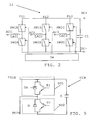
- Fig. 2 shows a block schematic outlining an example of a first type of voltage source converter 12.
- the voltage source converter 12 here includes a group of branches in the form of phase legs connected in parallel between two DC terminals DC+ and DC- for connection to the DC power transmission system.
- phase legs PL1, PL2, PL3 in order to enable connection to a three-phase AC transmission system. It should however be realized that as an alternative there may be for instance only two phase legs.
- Each phase leg PL1, PL2, PL3 has a first and second end point.
- each phase leg includes a lower and upper phase leg half and at the junction where the halves of a leg meet, a three-phase connection point AC1, AC2 and AC3 is provided.
- Each three-phase connection point AC1, AC2, AC3 is here connected to the corresponding phase leg via a respective inductor LAC1, LAC2, LAC3.
- Each half includes a switching arrangement SW1A, SW2A, SW1B, SW2B, SW1C, SW2C being controlled by a control unit 34.
- a capacitor C1 connected in parallel with the phase legs.
- the switching arrangements can each be provided in the form of one or more series connected combinations of primary switching element and anti-parallel secondary rectifying element, where the switching element may as an example be an IGBT transistor.
- Each such combination of primary switching element and anti-parallel secondary rectifying element is here denoted a switching unit.
- the control unit 34 controls the switching elements of the switching arrangements for converting AC power to DC power or vice versa.
- the two DC terminals DC+ and DC- here make up the DC side of the voltage source converter 12, while the AC terminals AC1, AC2 and AC3 make up the AC side of the voltage source converter.
- the exemplifying converter 12 may here be operated in two power directions.
- the control typically involves generating control signals by the control unit 34 in known fashion based on PWM modulation, for instance using a triangular saw-tooth wave as a reference signal, and supplying these control signals to the switching arrangements SW1A, SW1B, SW1C, SW2A, SW2B and SW2C.
- the control unit 34 has further DC fault current limiting functionality, which will be described later on.
- the voltage source converter may according to another variation of the present invention be realized in the form of voltage source converter cells being connected to each other in series.
- fig. 3 which shows a second type of voltage source converter 12, where the switching arrangements of each phase leg of the voltage source converter in fig. 1 has been replaced by a number or a string of voltage source converter cells.
- the second type of voltage source converter is thus a cell based voltage source converter. It should also be noted that the capacitor between the two DC terminals DC+ and DC- has been removed.
- the upper half of the first phase leg PL1 includes three cells CA1, CA2 and CA3, while the lower half of the first phase leg PL1 includes three cells CA4, CA5 and CA6.
- the upper half of the second phase leg PL2 includes three cells CB1, CB2 and CB3, while the lower half of the second phase leg PL2 includes three cells CB4, CB5 and CB6.
- the upper half of the third phase leg PL3 includes three cells CC1, CC2 and CC3, while the lower half of the third phase leg PL3 includes three cells CC4, CC5 and CC6.
- the numbers are here only chosen for exemplifying the principles of the present invention. It is often preferred to have many more cells in each phase leg, especially in HVDC applications.
- Fig. 4 schematically shows a first type of converter cell CCA that may be used in the voltage source converter of the second type.
- the cell CCA is a half-bridge converter cell and includes an energy storage element, here in the form of a capacitor C, which is connected in parallel with a first group of switching units.
- the switching units in the first group are connected in series with each other.
- the first group here includes a first switching unit SU1 and a second switching unit SU2 (shown as dashed boxes), where each switching unit SU1, SU2 may be realized in the form of a primary switching element that may be an IGBT (Insulated Gate Bipolar Transistor) transistor together with an anti-parallel secondary rectifying element.
- IGBT Insulated Gate Bipolar Transistor
- the first switching unit SU1 is of a first type, where the switching element is a first transistor T and here an IGBT and the rectifying element is a controllable rectifying element and here a thyristor TH.
- the primary switching element may also have the ability to block a negative voltage.
- a transistor may thus have the ability to withstand a negative voltage applied between collector and emitter. This may be obtained through providing the transistor with inherent negative voltage blocking capability or through series connection of the transistor with a diode.
- the second switching unit SU2 is here of a second type where the switching element is of the same type and here a second transistor T2, while the rectifying element is a non-controllable rectifying element and here a diode D. In fig.
- the diode D of the second switching unit SU2 is oriented upwards in the figure, which is towards the capacitor C, and connected in parallel between emitter and collector of the second transistor T2.
- the second switching unit SU2 is connected in series with and followed by the first switching unit SU1 that has the thyristor TH with the same orientation as the diode and connected in parallel with the first transistor T1.
- the cell has a first connection terminal TE1A and a second connection terminal TE2A, each providing a connection for the cell to a phase leg of the voltage source converter.
- the first connection terminal TE1A more particularly provides a connection from the phase leg to the junction between the first and the second switching unit SU1 and SU2, while the second connection terminal TE2A provides a connection from the phase leg to the junction between the first switching unit SU1 and the capacitor C.
- These connection terminals TE1A and TE2A thus provide points where the cell can be connected to the phase leg.
- connection of the first connection terminal TE1A thus joins the phase leg with the connection point or junction between two of the series connected switching units of the first group, here the first and second switching units SU1 and SU2, while the connection of the second connection terminal TE2A joins the phase leg with a connection point between the first group of series connected switching units and the energy storage element, which is here the connection point between the first switching unit SU1 and the capacitor C.
- a phase leg as shown in fig. 3 may for instance be obtained through connecting a first connection terminal of a first cell to the first DC terminal via an inductor, connecting a first connection terminal of a second cell to the second connection terminal of the first cell, connecting a first connection terminal of a third cell to the second connection terminal of the second cell, connecting a first connection terminal of a fourth cell to the second connection terminal of the third cell, connecting a first connection terminal of a fifth cell to the second connection terminal of the fourth cell, connecting a first connection terminal of a sixth cell to the second connection terminal of the fifth cell and connecting the second terminal of the sixth cell to the second DC terminal via an inductor.
- Fig. 5 schematically shows a second type of half-bridge converter cell CCB having the same type of components as the first type and being interconnected in the same way.
- the first switching unit SU1 is followed by the second switching unit SU2.
- connection terminal TE2B a connection terminal
- second connection terminal which provides a connection between the branch and the connection point between the first and the second switching units SU1 and SU2 as well as a connection terminal
- a first connection terminal TE1B which provides a connection between the branch and the junction between the first switching unit SU1 and the capacitor C.
- the first type of voltage source converter is provided with switching arrangements, at least in the upper phase leg halves, that are made up of switching units of the first type, while the voltage source converter of the second type includes cells of the first or the second type, at least in the upper phase leg halves, i.e. also includes such switching units of the first type.
- the switching units include units were there is a primary switching element together with an anti-parallel secondary controllable element.
- the voltage source converter according to the invention may be provided in relation to high voltage DC applications where large currents and voltages are used. In HVDC systems it is possible that a fault is created in the DC power transmission system, for instance in the first power line in fig. 1 .
- Such DC faults are hard to handle in DC power transmission systems.
- One reason for them being hard to handle is that the currents may become very high in the case of a fault.
- Another problem is that the system is a DC power transmission system, where the current is a DC current. This makes the breaking of power lines a rather complex affair.
- the present invention is directed towards addressing such issues.
- the normal way of providing a voltage source converter is to provide all switching units as switching element and non-controllable rectifying element pairs, i.e. as transistor and diode combinations. When this is the case, the current through the voltage source converter will increase when a DC fault occurs and the transistors will be blocked in order to avoid thermal damage. If the phase legs are solely made up of transistor-diode pairs, the converter will behave as a diode bridge i.e. the fault current is uncontrolled (in an active sense).
- a fault current path is here the path that the fault current will take through the voltage source converter.
- the voltage source converter is a traditional voltage source converter, such as the converter shown in fig. 2
- this is straightforward and involves replacing all diodes in at least one half of the phase legs with thyristors.
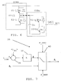
- fig. 6 schematically shows a first CCB1 and an n th CCBn cell of the second type connected between the positive DC terminal DC+ and the first AC terminal AC1 of the first leg of the voltage source converter of fig. 3 .
- Fig. 7 shows a block schematic of one way of realizing a thyristor control functionality 35 of the control unit.
- a first subtracting unit 36 which receives two signals i dc and i lim and supplies the result of a subtracting operation to an amplifying unit 38, which amplifies the difference with a gain k and provides a phase angle ⁇ as output to a switch 40.
- the switch 40 also receives a zero phase angle ⁇ 0 and is switchable between two positions based on two control signals F_DTC representing fault detection and F_RMV representing fault removal.
- the switch provides as its output a phase angle ⁇ c that is either of the two phase angles ⁇ or ⁇ 0 .
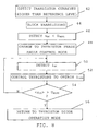
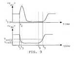
- fig. 1 , 3 , 6 and 7 schematically shows a flow chart including a number of method steps in a method for limiting the current in the DC power transmission system and being performed in the first voltage source converter 12, and to fig. 9 , which schematically shows the average current and average voltage of the first voltage source converter at the DC side in relation to a fault in the first power line.
- the thyristors TH1 and THn in the converter cell elements CCB of the first converter 12 are in normal operation, i.e. when there is no fault in the DC network 20, operated as diodes. This means that they are controlled by the control unit 34 according to a first control mode so that they will always conduct current as a positive voltage is applied over them.
- the switch 40 of the thyristor control functionality 35 of the control unit 34 in this mode is set to provide a phase angle ⁇ c that is a zero phase angle ⁇ 0 for firing the thyristors TH1 and THn.
- control unit may send a continuous sequence of gate current pulses, also known as "picket fence", to the thyristors in order to make sure that they turn on whenever they get forward biased.
- gate current pulses also known as "picket fence”
- the control unit instead automatically provides gate drive pulses whenever the thyristors are forward biased. In this way the thyristors provide a current path in the opposite direction of that of the transistors T1-1 and T1-n that act as switches. This means that in this first control mode the first type of switching units are controlled to act as transistors with anti-parallel diodes.
- the control unit 34 may thus determine that the current through the transistors are jeopardizing them and therefore block them. However, the current will still continue to rise and the voltage will also continue to fall. Therefore the fault is then detected, which detection may be carried out by the first converter 12 itself or by dedicated fault detection equipment provided in the DC power transmission system 20. This means that the control unit may receive a fault detection indication signal from such equipment or may determine the existence of a fault itself. Detection of a fault can thus be performed in a multitude of ways.
- the power component is a voltage and one characteristic of this voltage is the voltage level that is compared with a voltage level threshold. This means that as the voltage level at the DC side of the voltage source converter 12 is decreasing it is possible to detect a fault through detecting that this voltage level, and thus the voltage in the DC network, falls below a first threshold U REF1 , step 46, which first threshold is thus a first voltage level reference. This crossing of the first threshold is detected at a time t 3 .
- the detecting of a fault in this case involves comparing the voltage at the DC side of the converter with a first voltage reference and determining the there is a fault in dependence of if this voltage falls below the first voltage reference. In this case a determination is made that there is a fault if the voltage level falls below this voltage level threshold.
- Faults may alternatively be detected through sensing another characteristic, the rate of change of the voltage at the DC side of the voltage source converter, comparing this rate of change with a corresponding first rate of change threshold and determining the existence of a fault in case this rate of change is below this first rate of change threshold, which first rate of change threshold is normally negative. This means that a fault would be detected if the rate of change, which is negative, falls below this negative threshold.
- this rate of change is higher than the absolute value of the threshold. In this way it is possible to detect a fast drop of the voltage. It is also possible to detect a characteristic of another power component, the current, where the characteristic may be the current level. Here it is possible that the current level at the DC side of the voltage source converter is detected, compared with a corresponding current level threshold and the existence of a fault is determined if this current level threshold is exceeded. It is furthermore possible to detect another characteristic of the current at the DC side of the voltage source converter, the rate of change, compare this rate of change with a corresponding rate of change threshold and determine that there is a fault in case this rate of change is above this rate of change threshold, which threshold is normally positive. This means that a fast increase of the current would be detected. It should finally be mentioned that it is also possible with a combination of any of these detection techniques for detecting a fault.
- control unit 34 thereafter changes control mode for the thyristors of the switching units in the fault current path from the first control mode to a second control mode, which is to control these thyristors to act as controllable rectifying elements, i.e. normal thyristor control, or in other words phase angle control.
- the control unit 34 thus changes control mode from diode to phase angle control, step 48, which is done based on a fault detecting signal F_DTC, which may thus be generated internally in the control unit 34 or a signal received from an entity external to the control unit 34.
- phase angle control is based on the current i DC at the DC side of the first converter 12 and more particularly on the average current on the DC side. Therefore the current i DC at the DC side of the converter 12 is detected or measured, step 50.
- the control unit 34 then controls the controllable rectifying elements of the first converter based on the detected current. This involves controlling the thyristors for obtaining a set current limitation value i LIM , step 52.
- the current limit value i LIM can here be set to zero. However it may be desirable to continue to feed some current into the DC power transmission system. It may for instance be necessary to have some current in the DC power transmission system in order to perform selective detection of where in the system the fault is located in order to find out which parts of the DC power transmission system that are faulty and need to be disconnected. It may also be necessary to retain some currents in order to charge cable capacitances once the faulty part is disconnected. The fault current contribution can be substantially lower than the normal load current, since the indication of fault is obtained via the DC voltage.
- the fault current contribution from the first voltage source converter may be I LIM /m, where m is the number of voltage source converters that are interfacing the DC power transmission system.
- the fault is removed in the system, which is typically done through the first and second circuit breakers 30 and 32 disconnecting the first DC power line 12 from the DC power transmission system 20. This is done at time t 4 .
- the removal of the fault may then be detected. This detection may also here be performed in the system outside of the converter or in the converter itself.
- the control unit 34 therefore compares the average voltage ⁇ u DC > at the DC side of the first converter 12 with a second voltage reference U REF2 , step 54, and if this is exceeded, then the control unit 34 determines that the fault has been removed and returns to thyristor diode control mode, i.e.
- step 56 which is done at time t 5 .
- the control unit 34 thus resumes control of the controllable rectifying elements in the fault current path according to the first control mode. Then the transistors can also be unblocked and normal operation is thus restored. However if the average voltage did not exceed this second reference voltage U REF2 , step 54, thyristor control mode is continued, steps 50, 52.
- a switch back to the first control mode may be done through generating or receiving a control signal F_RMV indicating that the fault has been removed, which signal is supplied to the switch 40, which switches in order to once again supply the zero phase angle ⁇ 0 as output signal for controlling the thyristors.
- Removal of the fault may for instance be detected through sensing the rate of change of the voltage at the DC side of the voltage source converter, comparing this rate of change with a second rate of change threshold and detecting a removal of the fault in case this rate of change is above this second rate of change threshold, which threshold is normally positive. This means that a fast increase of the voltage would be detected. It should finally be mentioned that it is also possible with a combination of these detection techniques for detecting a removal of the fault.
- time interval t 4 - t 3 should be large enough for allowing safe determination of the location of the fault so that wrong disconnections are not made.
- the current limitation is set so low that the phase angle will be regulated to approximately ninety degrees and preferably slightly less than ninety degrees. This has the advantage of obtaining a current at the DC side of the converter that has a zero crossing. Because the current at the DC side has a zero-crossing, the circuit breakers in the DC power transmission system can be simplified. Because there are zero-crossings it is possible to use AC circuit breakers that are simpler in structure and often cheaper than regular DC breakers.
- all switching units of the cell are switching units of the first type. It is also possible that all switching units are of the first type also in voltage source converters of the first type.
- the step of blocking switching elements was performed before the fault was detected. However, it should be realized that the fault may as an alternative be detected simultaneously or before the switching elements are blocked.
- snubbers in order to limit the rate of change of the voltage at turn off as well as reactors for limiting the rate of change of the current at turn on. This may also be combined with a clamping arrangement.
- a snubber may for instance be placed in parallel with the thyristor, while a reactor may be placed in series with it.
- the switching units used in the cells have been described as employing transistors. These are with advantage IGBTs. It should be realized that other types of switching elements may be used, such as elements based on thyristors, MOSFET transistors, GTOs (Gate Turn-Off Thyristor) or IGCTs (Integrated Gate Commuted Thyristor). Also the controllable rectifying elements may be provided as GTOs or IGCTs.
- the control unit need not be provided as a part of a voltage source converter. It can be provided as a separate device that provides control signals to the voltage source converter.
- This control unit may be realized in the form of discrete components as indicated in fig. 7 . However, it may also be implemented in the form of a processor with accompanying program memory comprising computer program code that performs the desired control functionality when being run on the processor.
- This computer program product can be provided as a data carrier such as one or more CD ROM discs or one or more memory sticks carrying computer program code, which performs the above-described current limitation control functionality when being loaded into a control unit of a voltage source converter.
Landscapes
- Engineering & Computer Science (AREA)
- Power Engineering (AREA)
- Rectifiers (AREA)
- Inverter Devices (AREA)
Claims (29)
- Procédé pour limiter le courant dans un système de transport d'énergie en courant continu (20) au moyen d'un convertisseur de source de tension (12) comportant un chemin de courant de défaut entre un côté alternatif et un côté continu du convertisseur, ledit chemin de courant de défaut comportant au moins une unité de commutation (SU1) d'un premier type, chaque unité de commutation du premier type comportant un élément de commutation primaire (T1) ainsi qu'un élément de redressement commandable secondaire anti-parallèle (TH), le procédé comprenant les étapes consistant à :- bloquer (44) des éléments de commutation primaires (T1, T2) du convertisseur,- détecter (46) un défaut dans le système d'énergie en courant continu,- modifier (46) la commande des éléments de redressement commandables dans le chemin de courant de défaut pour la faire basculer d'un premier mode de commande sur un deuxième mode de commande, le premier mode de commande servant à commander les éléments de redressement commandables pour qu'ils se comportent comme des éléments de redressement non commandables de façon à être toujours conducteurs de courant lorsqu'une tension positive est appliquée à leurs bornes, et le deuxième mode de commande servant à commander les éléments de redressement commandables pour qu'ils se comportent comme des éléments de redressement commandables, et- commander (52), selon ledit deuxième mode de commande, les éléments de redressement commandables du chemin de courant de défaut dans le but de limiter le courant du côté continu du convertisseur.
- Procédé selon la revendication 1, comprenant en outre l'étape consistant à détecter (50) le courant (iDC) du côté continu du convertisseur, et l'étape consistant à commander les éléments de redressement commandables du chemin de courant de défaut comprend l'étape consistant à commander (52) les éléments de redressement commandables du chemin de courant de défaut sur la base de ce courant détecté.
- Procédé selon la revendication 2, dans lequel l'étape consistant à commander les éléments de redressement commandables comprend l'étape consistant à commander le courant moyen (<iDC>) du côté continu du convertisseur pour l'amener à une valeur de limitation de courant fixée (iLIM).
- Procédé selon l'une quelconque des revendications précédentes, dans lequel l'étape consistant à détecter un défaut dans le système d'énergie en courant continu consiste à comparer au moins une caractéristique d'au moins une composante d'énergie du côté continu du convertisseur de source de tension à au moins un seuil de composante d'énergie et à établir qu'un défaut existe si la caractéristique de la composante d'énergie passe ce seuil.
- Procédé selon la revendication 4, dans lequel une composante d'énergie constitue la tension (uDC), une caractéristique constitue le niveau de cette tension, un seuil de composante d'énergie constitue une première référence de niveau de la tension (UREF1) et l'étape consistant à établir qu'un défaut existe consiste à établir si la tension passe sous la première référence de niveau de la tension.
- Procédé selon la revendication 4 ou 5, dans lequel une composante d'énergie constitue la tension (uDC), une caractéristique constitue le taux de variation de cette tension, un seuil de composante d'énergie constitue un seuil de taux de variation de la tension et l'étape consistant à établir qu'un défaut existe consiste à établir si le taux de variation de la tension passe sous ce seuil de taux de variation de la tension.
- Procédé selon l'une quelconque des revendications 4 à 6, dans lequel une composante d'énergie constitue le courant (iDC), une caractéristique constitue le niveau de ce courant, un seuil de composante d'énergie constitue un seuil de niveau du courant et l'étape consistant à établir qu'un défaut existe consiste à établir si le courant passe au-dessus de ce seuil de niveau du courant.
- Procédé selon l'une quelconque des revendications 4 à 7, dans lequel une composante d'énergie constitue le courant (iDC), une caractéristique constitue le taux de variation de ce courant, un seuil de composante d'énergie constitue un seuil de taux de variation du courant et l'étape consistant à établir qu'un défaut existe consiste à établir si le taux de variation du courant passe au-dessus de ce seuil de taux de variation du courant.
- Procédé selon l'une quelconque des revendications précédentes, comprenant en outre l'étape consistant à détecter (54) une suppression du défaut et reprendre (56) la commande des éléments de redressement commandables du chemin de courant de défaut selon le premier mode de commande sur la base de ladite détection (F_RMV) de la suppression du défaut.
- Procédé selon la revendication 9, dans lequel l'étape consistant à détecter une suppression du défaut comprend l'étape consistant à comparer la tension moyenne (<uDC>) du côté continu à une deuxième référence de tension (UREF2) et établir que le défaut a été supprimé si cette tension moyenne passe au-dessus de la deuxième référence de tension.
- Procédé selon l'une quelconque des revendications précédentes, dans lequel l'étape consistant à commander selon le deuxième mode de commande consiste à commander l'élément de redressement commandable pour assurer un passage par zéro du courant du côté continu du convertisseur.
- Procédé selon l'une quelconque des revendications précédentes, dans lequel la commande selon le deuxième mode de commande comprend une commande de l'angle de phase de l'élément de redressement commandable.
- Procédé selon la revendication 12, dans lequel l'angle de phase est commandé pour prendre une valeur d'environ quatre-vingt-dix degrés.
- Procédé selon l'une quelconque des revendications précédentes, dans lequel chaque unité de commutation du premier type fait partie d'une cellule du convertisseur de source de tension comportant un élément d'accumulation d'énergie et une unité de commutation (SU2) d'un deuxième type et comprenant un élément de commutation primaire (T2) ainsi qu'un élément de redressement non commandable secondaire anti-parallèle (D), les unités de commutation (SU1, SU2) étant montées en série l'une avec l'autre et ces unités de commutation montées en série étant montées en parallèle avec l'élément d'accumulation d'énergie (C1C).
- Convertisseur de source de tension (12) pour limiter le courant dans un système de transport d'énergie en courant continu (20), pourvu d'un côté alternatif et d'un côté continu et présentant un chemin de courant de défaut entre ledit côté alternatif et ledit côté continu, ledit convertisseur de source de tension comprenant :- au moins une unité de commutation (SU1) d'un premier type dans ledit chemin de courant de défaut, chaque unité de commutation du premier type comportant un élément de commutation primaire (T1) ainsi qu'un élément de redressement commandable secondaire anti-parallèle (TH), et- une unité de commande (34) caractérisée en ce qu'elle est configurée, sur la base d'un défaut détecté (F_DTC) dans le système d'énergie en courant continu lorsque les éléments de commutation primaires du convertisseur sont bloqués, pour- modifier (40) la commande desdits éléments de redressement commandables pour la faire basculer d'un premier mode de commande sur un deuxième mode de commande, le premier mode de commande servant à commander les éléments de redressement commandables pour qu'ils se comportent comme des éléments de redressement non commandables de façon à être toujours conducteurs de courant lorsqu'une tension positive est appliquée à leurs bornes, et le deuxième mode de commande servant à commander les éléments de redressement commandables pour qu'ils se comportent comme des éléments de redressement commandables, et- commander, selon ledit deuxième mode de commande, les éléments de redressement commandables du chemin de courant de défaut dans le but de limiter le courant du côté continu du convertisseur.
- Convertisseur de source de tension selon la revendication 15, dans lequel l'unité de commande est configurée en outre, lorsqu'elle commande les éléments de redressement commandables du chemin de courant de défaut, pour commander les éléments de redressement commandables sur la base du courant détecté (iDC) du côté continu du convertisseur.
- Convertisseur de source de tension (12) selon la revendication 16, dans lequel l'unité de commande est configurée, lorsqu'elle est configurée pour commander les éléments de redressement du chemin de courant de défaut sur la base du courant détecté (iDC) du côté continu du convertisseur, pour commander (36, 38) le courant moyen (<iDC>) du côté continu du convertisseur pour l'amener à une valeur de limitation de courant fixée (ILIM).
- Convertisseur de source de tension (12) selon l'une quelconque des revendications 15 à 17, dans lequel l'unité de commande est configurée, lorsqu'elle détecte un défaut dans le système d'énergie en courant continu, pour comparer au moins une caractéristique d'au moins une composante d'énergie du côté continu du convertisseur de source de tension à au moins un seuil de composante d'énergie et à établir qu'un défaut existe si la caractéristique de la composante d'énergie passe ce seuil.
- Convertisseur de source de tension (12) selon la revendication 18, dans lequel une composante d'énergie constitue la tension (uDC), une caractéristique constitue le niveau de cette tension, un seuil de composante d'énergie constitue une première référence de niveau de la tension (UREFL1) et l'unité de commande est configurée, lorsqu'elle détecte un défaut dans le système d'énergie en courant continu, pour établir qu'un défaut existe si la tension passe sous la première référence de niveau de la tension.
- Convertisseur de source de tension (12) selon la revendication 18 ou 19, dans lequel une composante d'énergie constitue la tension (uDC), une caractéristique constitue le taux de variation de cette tension, un seuil de composante d'énergie constitue un seuil de taux de variation de la tension et l'unité de commande est configurée, lorsqu'elle détecte un défaut dans le système d'énergie en courant continu, pour établir qu'un défaut existe si le taux de variation de la tension passe sous ce seuil de taux de variation de la tension.
- Convertisseur de source de tension (12) selon l'une quelconque des revendications 18 à 20, dans lequel une composante d'énergie constitue le courant (iDC), une caractéristique constitue le niveau de ce courant, un seuil de composante d'énergie constitue un seuil de niveau du courant et l'unité de commande est configurée, lorsqu'elle détecte un défaut dans le système d'énergie en courant continu, pour établir qu'un défaut existe si le courant passe au-dessus de ce seuil de niveau du courant.
- Convertisseur de source de tension (12) selon l'une quelconque des revendications 18 à 21, dans lequel une composante d'énergie constitue le courant (iDC), une caractéristique constitue le taux de variation de ce courant, un seuil de composante d'énergie constitue un seuil de taux de variation du courant et l'unité de commande est configurée, lorsqu'elle détecte un défaut dans le système d'énergie en courant continu, pour établir qu'un défaut existe si le taux de variation du courant passe au-dessus de ce seuil de taux de variation du courant.
- Convertisseur de source de tension (12) selon l'une quelconque des revendications 15 à 22, l'unité de commande étant configurée en outre pour détecter une suppression du défaut et reprendre la commande des éléments de redressement commandables du chemin de courant de défaut selon le premier mode de commande sur la base de ladite détection (F_RMV) de la suppression du défaut.
- Convertisseur de source de tension (12) selon la revendication 23, dans lequel l'unité de commande est configurée, lorsqu'elle est configurée pour détecter une suppression du défaut, pour comparer la tension moyenne (<uDC>) du côté continu à une deuxième référence de tension (UREF2) et établir que le défaut a été supprimé si cette tension moyenne passe au-dessus de la deuxième référence de tension.
- Convertisseur de source de tension (12) selon l'une quelconque des revendications 15 à 24, dans lequel l'unité de commande est configurée, lorsqu'elle commande selon le deuxième mode de commande, pour commander l'élément de redressement commandable pour assurer un passage par zéro du courant du côté continu du convertisseur.
- Convertisseur de source de tension (12) selon l'une quelconque des revendications 15 à 25, dans lequel l'unité de commande est configurée, lorsqu'elle commande selon le deuxième mode de commande, pour effectuer une commande de l'angle de phase de l'élément de redressement commandable.
- Convertisseur de source de tension (12) selon la revendication 26, dans lequel l'angle de phase est commandé pour prendre une valeur d'environ quatre-vingt-dix degrés.
- Convertisseur de source de tension (12) selon l'une quelconque des revendications 15 à 27, dans lequel chaque unité de commutation du premier type fait partie d'une cellule du convertisseur de source de tension comportant un élément d'accumulation d'énergie et une unité de commutation (SU2) d'un deuxième type et comprenant un élément de commutation primaire (T2) ainsi qu'un élément de redressement non commandable secondaire anti-parallèle (D), les unités de commutation (SU1, SU2) étant montées en série l'une avec l'autre et ces unités de commutation montées en série étant montées en parallèle avec l'élément d'accumulation d'énergie (C1C).
- Produit-programme d'ordinateur pour limiter le courant dans un système de transport d'énergie en courant continu (20) au moyen d'un convertisseur de source de tension (12) comportant un chemin de courant de défaut entre un côté alternatif et un côté continu du convertisseur, ledit chemin de courant de défaut comportant au moins une unité de commutation (SU1) d'un premier type, chaque unité de commutation du premier type comportant un élément de commutation primaire (T1) ainsi qu'un élément de redressement commandable secondaire anti-parallèle (TH),
ledit programme d'ordinateur étant chargeable dans une unité de commande du convertisseur de source de tension et comprenant un moyen formant code de programme d'ordinateur pour amener l'unité de commande, une fois ledit programme chargé dans ladite unité de commande, à :- modifier, sur la base d'un défaut détecté dans le système de transport d'énergie en courant continu lorsque les éléments de commutation primaires du convertisseur sont bloqués, la commande desdits éléments de redressement commandables pour la faire basculer d'un premier mode de commande sur un deuxième mode de commande, le premier mode de commande servant à commander les éléments de redressement commandables pour qu'ils se comportent comme des éléments de redressement non commandables de façon à être toujours conducteurs de courant lorsqu'une tension positive est appliquée à leurs bornes, et le deuxième mode de commande servant à commander les éléments de redressement commandables pour qu'ils se comportent comme des éléments de redressement commandables, et- commander, selon ledit deuxième mode de commande, les éléments de redressement commandables du chemin de courant de défaut dans le but de limiter le courant du côté continu du convertisseur.
Applications Claiming Priority (1)
| Application Number | Priority Date | Filing Date | Title |
|---|---|---|---|
| PCT/EP2009/061815 WO2011029480A1 (fr) | 2009-09-11 | 2009-09-11 | Limitation de courant de defaut dans des systemes de transmission de puissance en courant continu |
Publications (2)
| Publication Number | Publication Date |
|---|---|
| EP2476193A1 EP2476193A1 (fr) | 2012-07-18 |
| EP2476193B1 true EP2476193B1 (fr) | 2015-02-25 |
Family
ID=42133380
Family Applications (1)
| Application Number | Title | Priority Date | Filing Date |
|---|---|---|---|
| EP09782924.6A Active EP2476193B1 (fr) | 2009-09-11 | 2009-09-11 | Limitation de courant de defaut dans des systemes de transmission de puissance en courant continu |
Country Status (4)
| Country | Link |
|---|---|
| US (1) | US8830708B2 (fr) |
| EP (1) | EP2476193B1 (fr) |
| CN (1) | CN102484430B (fr) |
| WO (1) | WO2011029480A1 (fr) |
Families Citing this family (58)
| Publication number | Priority date | Publication date | Assignee | Title |
|---|---|---|---|---|
| KR101507560B1 (ko) | 2009-07-31 | 2015-04-07 | 알스톰 그리드 유케이 리미티드 | 구성 가능한 하이브리드 컨버터 회로 |
| JP5176006B2 (ja) * | 2009-10-06 | 2013-04-03 | エー ビー ビー リサーチ リミテッド | 電圧形コンバータ |
| WO2011113471A1 (fr) | 2010-03-15 | 2011-09-22 | Areva T&D Uk Ltd | Compensateur statique de puissance réactive doté d'un convertisseur à plusieurs niveaux |
| CN103026603B (zh) | 2010-06-18 | 2016-04-13 | 阿尔斯通技术有限公司 | 用于hvdc传输和无功功率补偿的转换器 |
| WO2012116738A1 (fr) * | 2011-03-01 | 2012-09-07 | Abb Research Ltd | Limitation du courant de défaut dans des systèmes de transmission de courant électrique continu |
| US9350250B2 (en) | 2011-06-08 | 2016-05-24 | Alstom Technology Ltd. | High voltage DC/DC converter with cascaded resonant tanks |
| CN103891121B (zh) | 2011-08-01 | 2016-11-23 | 阿尔斯通技术有限公司 | 直流-直流转换器组件 |
| CA2848325C (fr) | 2011-11-07 | 2018-03-27 | General Electric Technology Gmbh | Circuit de commande |
| CN103959634B (zh) | 2011-11-17 | 2017-09-01 | 通用电气技术有限公司 | 用于hvdc应用的混合ac/dc转换器 |
| WO2013115915A1 (fr) * | 2012-01-31 | 2013-08-08 | Atlantic Grid Operations A., Llc | Commande et protection d'un réseau d'alimentation c.c. |
| IN2014MN01647A (fr) * | 2012-03-01 | 2015-05-22 | Alstom Technology Ltd | |
| EP2810350B1 (fr) * | 2012-03-13 | 2018-10-24 | Siemens Aktiengesellschaft | Dispositif de distribution d' énergie |
| GB201209110D0 (en) | 2012-05-24 | 2012-07-04 | Alstom Technology Ltd | Method of fault clearance |
| WO2014032701A1 (fr) * | 2012-08-28 | 2014-03-06 | Abb Technology Ltd | Dispositif de convertisseur et procédé correspondant |
| US9312696B2 (en) | 2012-10-02 | 2016-04-12 | Abb Technology Ltd | Method and associated transmission system |
| CN103066614A (zh) * | 2012-12-31 | 2013-04-24 | 南方电网科学研究院有限责任公司 | 一种多端柔性直流输电系统及其启动方法 |
| EP2768133B1 (fr) * | 2013-02-14 | 2015-11-04 | ABB Technology Ltd | Cellule de convertisseur à pertes de puissance réduites, convertisseur multiniveau haute tension et procédé associé |
| CN103245885B (zh) * | 2013-04-27 | 2015-11-04 | 国家电网公司 | 一体化的电力故障指示与状态监测逻辑判断方法 |
| CN103280989B (zh) * | 2013-05-15 | 2017-02-08 | 南京南瑞继保电气有限公司 | 一种换流器及其控制方法 |
| US9093240B2 (en) | 2013-05-15 | 2015-07-28 | International Business Machines Corporation | Direct current ground fault interrupter |
| DE102013109714A1 (de) * | 2013-09-05 | 2015-03-05 | Ge Energy Power Conversion Gmbh | Verfahren zum Betreiben einer elektrischen Schaltung sowie elektrische Schaltung |
| CN103618332B (zh) * | 2013-11-27 | 2016-01-20 | 国家电网公司 | 一种cscc-hvdc系统中可控电容的控制方法 |
| EP2910959B1 (fr) * | 2014-02-19 | 2021-09-08 | General Electric Technology GmbH | Localisation des pannes dans des réseaux à courant continu |
| CN107210603B (zh) | 2014-05-04 | 2020-07-14 | Abb瑞士股份有限公司 | 基于转换器的dc配电系统中的故障保护 |
| CN104052026B (zh) * | 2014-05-29 | 2016-05-25 | 华中科技大学 | 用于模块化多电平换流器的子模块拓扑及其应用 |
| KR101595658B1 (ko) * | 2014-07-28 | 2016-02-19 | 공주대학교 산학협력단 | 누설전류 검출 장치 및 방법 |
| EP3046196B1 (fr) | 2015-01-16 | 2019-05-15 | General Electric Technology GmbH | Procédé permettant d'éliminer une défaillance dans un réseau électrique à courant continu à haute tension |
| EP3062429A1 (fr) | 2015-02-27 | 2016-08-31 | General Electric Technology GmbH | Convertisseur de source de tension avec limitation de courant |
| EP3062413A1 (fr) * | 2015-02-27 | 2016-08-31 | Alstom Technology Ltd | Convertisseur de source de tension et commande de celui-ci |
| GB2536894B (en) * | 2015-03-30 | 2021-06-23 | General Electric Technology Gmbh | Converters |
| GB2537851B (en) * | 2015-04-28 | 2017-08-09 | General Electric Technology Gmbh | Bipolar DC power transmission scheme |
| US10326355B2 (en) * | 2015-07-14 | 2019-06-18 | Mitsubishi Electric Corporation | Power conversion device |
| GB2541465A (en) * | 2015-08-21 | 2017-02-22 | General Electric Technology Gmbh | Electrical assembly |
| CN105490258B (zh) * | 2015-12-21 | 2018-12-28 | 国网湖北省电力公司 | 多端柔性直流输电系统的直流故障判断方法及控制方法 |
| CN105552947A (zh) * | 2016-01-13 | 2016-05-04 | 特变电工新疆新能源股份有限公司 | 一种柔性直流输电系统直流单极接地故障检测方法 |
| CN105656343A (zh) * | 2016-01-27 | 2016-06-08 | 邓富金 | 基于晶闸管的模块化多电平变换器及其运行方法 |
| CN105656071B (zh) * | 2016-03-11 | 2018-07-31 | 特变电工新疆新能源股份有限公司 | 一种适用于无双端通信的柔直低穿控制方法 |
| US10063161B2 (en) * | 2016-10-18 | 2018-08-28 | Abb Schweiz Ag | Active neutral point clamped converter control system and method |
| US10411587B2 (en) | 2016-12-14 | 2019-09-10 | Abb Schweiz Ag | Fault isolation and system restoration using power converter |
| US10516260B2 (en) * | 2017-03-01 | 2019-12-24 | Hewlett Packard Enterprise Development Lp | Multi-node system fault management |
| CN108667328B (zh) * | 2017-03-27 | 2023-01-10 | 日立能源瑞士股份公司 | 用于控制多个转换器的操作的方法 |
| CN111357162B (zh) * | 2017-11-17 | 2021-07-13 | Abb电网瑞士股份公司 | 直流电力系统中的故障处理 |
| EP3729583B1 (fr) | 2017-12-21 | 2022-06-01 | Hitachi Energy Switzerland AG | Commande sans communication d'une station de convertisseur |
| EP3531523B1 (fr) * | 2018-02-23 | 2022-05-11 | General Electric Technology GmbH | Gestion de défaut |
| US11177662B2 (en) * | 2018-05-18 | 2021-11-16 | Siemens Energy Global GmbH & Co. KG | Monitoring of a high-voltage DC transmission |
| EP3797460A1 (fr) * | 2018-07-17 | 2021-03-31 | Siemens Energy Global GmbH & Co. KG | Procédé et dispositif pour détecter un défaut dans une ligne de transport d'énergie électrique en courant continu haute tension et pour générer un signal de déclenchement destiné à un disjoncteur à courant continu |
| US11511638B2 (en) * | 2018-07-25 | 2022-11-29 | Volvo Truck Corporation | Electrical power converter unit, an electrical power conversion device and an industrial vehicle including this electrical power converter unit |
| CN109494692B (zh) * | 2018-10-31 | 2022-07-01 | 中国电力科学研究院有限公司 | 一种获取柔直电网直流双极线路故障措施量的方法及系统 |
| CN109474169B (zh) * | 2018-12-24 | 2020-05-05 | 北京四方继保自动化股份有限公司 | 一种基于直流电压模糊控制的mmc直流侧故障电流控制方法 |
| EP3694068B1 (fr) | 2019-02-11 | 2023-10-18 | GE Energy Power Conversion Technology Ltd | Système de commutation statique et de limitation d'un courant continu |
| FR3098036B1 (fr) * | 2019-06-26 | 2021-06-18 | Inst Supergrid | Procédé de commande d’un réseau de transmission électrique |
| US11101640B1 (en) * | 2020-07-29 | 2021-08-24 | Abb Schweiz | Solid-state protection for direct current networks |
| WO2023057069A1 (fr) * | 2021-10-08 | 2023-04-13 | Huawei Digital Power Technologies Co., Ltd. | Commande insensible aux défaillances d'un transformateur à semi-conducteurs |
| WO2023117101A1 (fr) * | 2021-12-23 | 2023-06-29 | Hitachi Energy Switzerland Ag | Procédé de coupure d'un courant continu dans un système à courant continu à haute tension à bornes multiples |
| EP4468549A1 (fr) * | 2023-05-26 | 2024-11-27 | General Electric Technology GmbH | Ameliorations apportees a des systemes de freinage dynamique pour reseaux de transmission de puissance bipolaires |
| CN116853158B (zh) * | 2023-07-31 | 2026-01-20 | 深蓝汽车科技有限公司 | 低压电路控制方法、装置、设备、存储介质及系统 |
| CN117526719A (zh) * | 2023-11-07 | 2024-02-06 | 中车株洲电力机车研究所有限公司 | 一种直流变换装置及系统 |
| CN117878940B (zh) * | 2023-12-08 | 2024-07-09 | 上海交通大学 | 计及源-网-荷协同的连锁故障阻断控制方法及系统 |
Family Cites Families (13)
| Publication number | Priority date | Publication date | Assignee | Title |
|---|---|---|---|---|
| US4156896A (en) * | 1978-04-10 | 1979-05-29 | General Electric Company | Method of controlling a power conversion system |
| GB2124411B (en) * | 1982-07-02 | 1986-03-26 | Tokyo Shibaura Electric Co | Temperature control apparatus |
| US4879639A (en) * | 1987-05-11 | 1989-11-07 | Fuji Electric Co., Ltd. | Power converter for driving an AC motor at a variable speed |
| JP2560530B2 (ja) * | 1990-09-26 | 1996-12-04 | 新神戸電機株式会社 | 電力変換器 |
| JPH1127853A (ja) | 1997-06-30 | 1999-01-29 | Yaskawa Electric Corp | 主回路電源の保護回路 |
| JP2001078470A (ja) * | 1999-09-03 | 2001-03-23 | Electric Power Dev Co Ltd | 交直変換器とその制御装置及び直流送電システム |
| SE514965C2 (sv) * | 1999-09-22 | 2001-05-21 | Abb Ab | Kontrollutrustning för en tyristorstyrd seriekondensatorutrustning, och förfarande för styrning därav |
| US20020024828A1 (en) * | 2000-08-31 | 2002-02-28 | Hidetake Hayashi | Inverter suitable for use with portable AC power supply unit |
| US6624993B1 (en) | 2000-11-22 | 2003-09-23 | The Regents Of The University Of California | Adjustable direct current and pulsed circuit fault current limiter |
| SE523457C2 (sv) * | 2001-05-17 | 2004-04-20 | Abb Ab | VSC-strömriktare flrsedd med resonanskrets för kommuntering, jämte tillhörande förfarande, datorprogramprodukt och datorläsbart medium |
| JP4645808B2 (ja) * | 2004-12-17 | 2011-03-09 | サンケン電気株式会社 | 3相電力変換装置 |
| ATE523951T1 (de) | 2006-12-08 | 2011-09-15 | Siemens Ag | Halbleiterschutzelemente zur beherrschung von dc- seitigen kurzschlüssen bei spannungszwischenkreisumrichtern |
| ES2693612T3 (es) * | 2007-03-13 | 2018-12-12 | Siemens Aktiengesellschaft | Procedimiento para la limitación de daños de un convertidor de corriente que presenta semiconductores de potencia en caso de un cortocircuito en el circuito intermedio de tensión continua |
-
2009
- 2009-09-11 WO PCT/EP2009/061815 patent/WO2011029480A1/fr not_active Ceased
- 2009-09-11 US US13/395,359 patent/US8830708B2/en not_active Expired - Fee Related
- 2009-09-11 EP EP09782924.6A patent/EP2476193B1/fr active Active
- 2009-09-11 CN CN200980161342.9A patent/CN102484430B/zh active Active
Also Published As
| Publication number | Publication date |
|---|---|
| EP2476193A1 (fr) | 2012-07-18 |
| CN102484430B (zh) | 2016-08-31 |
| WO2011029480A1 (fr) | 2011-03-17 |
| US20120201059A1 (en) | 2012-08-09 |
| CN102484430A (zh) | 2012-05-30 |
| US8830708B2 (en) | 2014-09-09 |
Similar Documents
| Publication | Publication Date | Title |
|---|---|---|
| EP2476193B1 (fr) | Limitation de courant de defaut dans des systemes de transmission de puissance en courant continu | |
| WO2012116738A1 (fr) | Limitation du courant de défaut dans des systèmes de transmission de courant électrique continu | |
| US7321500B2 (en) | Electric power converter | |
| Zhang et al. | Review of modular multilevel converter based multi-terminal HVDC systems for offshore wind power transmission | |
| EP2730016B1 (fr) | Convertisseur cc/cc pour haute tension | |
| KR101275925B1 (ko) | 멀티―터미널 hvdc 전력 전송 네트워크에서의 dc 전압 보상 | |
| US20230327453A1 (en) | Photovoltaic System, Protection Method, and Inverter System | |
| EP3285388B1 (fr) | Dispositif de conversion de puissance électrique | |
| US9847737B2 (en) | Modular multilevel converter leg with flat-top PWM modulation, converter and hybrid converter topologies | |
| EP3375082B1 (fr) | Convertisseur modulaire multiniveaux pour gestion de défauts côté ca | |
| US11777401B2 (en) | Fault tolerant AC-DC chain-link converter | |
| ES2936642T3 (es) | Fuente de alimentación del horno de arco con circuito convertidor | |
| US20260018991A1 (en) | Power conversion device and offshore wind power generation system | |
| US20180013290A1 (en) | Control circuit | |
| CN113690919B (zh) | 具有电网换相的变流器的变流器装置和用于启动其的方法 | |
| Balasubramaniam et al. | Pole balancing and thermal management in multiterminal HVDC grids using single H-bridge-based current flow controllers | |
| WO2007108427A1 (fr) | Regulateur de tension | |
| US12456932B2 (en) | Power conversion device | |
| EP4071996A1 (fr) | Dispositif de conversion de puissance | |
| WO2013044940A1 (fr) | Borne vsc-hvdc sans transformateur complet et doté d'un condensateur monté en série | |
| JP2019054641A (ja) | 電力変換装置 | |
| US12149068B2 (en) | Phase-controlled IGBT bridge type, GTO bridge type, and hybrid IGBT/semi-passive, GTO/semi-passive types fault current limiters (FCLs) | |
| US20240055865A1 (en) | Controller for power electronic device | |
| Poyiadjis | A new cell bypass arrangement and control for modular multilevel converters based on thyristor forced commutation circuit | |
| KR20160080020A (ko) | Mmc 컨버터의 서브모듈용 전원제어장치 |
Legal Events
| Date | Code | Title | Description |
|---|---|---|---|
| PUAI | Public reference made under article 153(3) epc to a published international application that has entered the european phase |
Free format text: ORIGINAL CODE: 0009012 |
|
| 17P | Request for examination filed |
Effective date: 20120411 |
|
| AK | Designated contracting states |
Kind code of ref document: A1 Designated state(s): AT BE BG CH CY CZ DE DK EE ES FI FR GB GR HR HU IE IS IT LI LT LU LV MC MK MT NL NO PL PT RO SE SI SK SM TR |
|
| DAX | Request for extension of the european patent (deleted) | ||
| GRAP | Despatch of communication of intention to grant a patent |
Free format text: ORIGINAL CODE: EPIDOSNIGR1 |
|
| INTG | Intention to grant announced |
Effective date: 20140923 |
|
| GRAP | Despatch of communication of intention to grant a patent |
Free format text: ORIGINAL CODE: EPIDOSNIGR1 |
|
| INTG | Intention to grant announced |
Effective date: 20141223 |
|
| GRAS | Grant fee paid |
Free format text: ORIGINAL CODE: EPIDOSNIGR3 |
|
| GRAA | (expected) grant |
Free format text: ORIGINAL CODE: 0009210 |
|
| AK | Designated contracting states |
Kind code of ref document: B1 Designated state(s): AT BE BG CH CY CZ DE DK EE ES FI FR GB GR HR HU IE IS IT LI LT LU LV MC MK MT NL NO PL PT RO SE SI SK SM TR |
|
| REG | Reference to a national code |
Ref country code: GB Ref legal event code: FG4D |
|
| REG | Reference to a national code |
Ref country code: CH Ref legal event code: EP |
|
| REG | Reference to a national code |
Ref country code: IE Ref legal event code: FG4D |
|
| REG | Reference to a national code |
Ref country code: DE Ref legal event code: R096 Ref document number: 602009029617 Country of ref document: DE Effective date: 20150409 |
|
| REG | Reference to a national code |
Ref country code: AT Ref legal event code: REF Ref document number: 712724 Country of ref document: AT Kind code of ref document: T Effective date: 20150415 |
|
| REG | Reference to a national code |
Ref country code: NL Ref legal event code: VDEP Effective date: 20150225 |
|
| REG | Reference to a national code |
Ref country code: AT Ref legal event code: MK05 Ref document number: 712724 Country of ref document: AT Kind code of ref document: T Effective date: 20150225 |
|
| REG | Reference to a national code |
Ref country code: LT Ref legal event code: MG4D |
|
| PG25 | Lapsed in a contracting state [announced via postgrant information from national office to epo] |
Ref country code: FI Free format text: LAPSE BECAUSE OF FAILURE TO SUBMIT A TRANSLATION OF THE DESCRIPTION OR TO PAY THE FEE WITHIN THE PRESCRIBED TIME-LIMIT Effective date: 20150225 Ref country code: LT Free format text: LAPSE BECAUSE OF FAILURE TO SUBMIT A TRANSLATION OF THE DESCRIPTION OR TO PAY THE FEE WITHIN THE PRESCRIBED TIME-LIMIT Effective date: 20150225 Ref country code: NO Free format text: LAPSE BECAUSE OF FAILURE TO SUBMIT A TRANSLATION OF THE DESCRIPTION OR TO PAY THE FEE WITHIN THE PRESCRIBED TIME-LIMIT Effective date: 20150525 Ref country code: SE Free format text: LAPSE BECAUSE OF FAILURE TO SUBMIT A TRANSLATION OF THE DESCRIPTION OR TO PAY THE FEE WITHIN THE PRESCRIBED TIME-LIMIT Effective date: 20150225 Ref country code: HR Free format text: LAPSE BECAUSE OF FAILURE TO SUBMIT A TRANSLATION OF THE DESCRIPTION OR TO PAY THE FEE WITHIN THE PRESCRIBED TIME-LIMIT Effective date: 20150225 Ref country code: ES Free format text: LAPSE BECAUSE OF FAILURE TO SUBMIT A TRANSLATION OF THE DESCRIPTION OR TO PAY THE FEE WITHIN THE PRESCRIBED TIME-LIMIT Effective date: 20150225 |
|
| PG25 | Lapsed in a contracting state [announced via postgrant information from national office to epo] |
Ref country code: GR Free format text: LAPSE BECAUSE OF FAILURE TO SUBMIT A TRANSLATION OF THE DESCRIPTION OR TO PAY THE FEE WITHIN THE PRESCRIBED TIME-LIMIT Effective date: 20150526 Ref country code: AT Free format text: LAPSE BECAUSE OF FAILURE TO SUBMIT A TRANSLATION OF THE DESCRIPTION OR TO PAY THE FEE WITHIN THE PRESCRIBED TIME-LIMIT Effective date: 20150225 Ref country code: IS Free format text: LAPSE BECAUSE OF FAILURE TO SUBMIT A TRANSLATION OF THE DESCRIPTION OR TO PAY THE FEE WITHIN THE PRESCRIBED TIME-LIMIT Effective date: 20150625 Ref country code: LV Free format text: LAPSE BECAUSE OF FAILURE TO SUBMIT A TRANSLATION OF THE DESCRIPTION OR TO PAY THE FEE WITHIN THE PRESCRIBED TIME-LIMIT Effective date: 20150225 |
|
| REG | Reference to a national code |
Ref country code: FR Ref legal event code: PLFP Year of fee payment: 7 |
|
| PG25 | Lapsed in a contracting state [announced via postgrant information from national office to epo] |
Ref country code: NL Free format text: LAPSE BECAUSE OF FAILURE TO SUBMIT A TRANSLATION OF THE DESCRIPTION OR TO PAY THE FEE WITHIN THE PRESCRIBED TIME-LIMIT Effective date: 20150225 |
|
| PG25 | Lapsed in a contracting state [announced via postgrant information from national office to epo] |
Ref country code: SK Free format text: LAPSE BECAUSE OF FAILURE TO SUBMIT A TRANSLATION OF THE DESCRIPTION OR TO PAY THE FEE WITHIN THE PRESCRIBED TIME-LIMIT Effective date: 20150225 Ref country code: RO Free format text: LAPSE BECAUSE OF FAILURE TO SUBMIT A TRANSLATION OF THE DESCRIPTION OR TO PAY THE FEE WITHIN THE PRESCRIBED TIME-LIMIT Effective date: 20150225 Ref country code: CZ Free format text: LAPSE BECAUSE OF FAILURE TO SUBMIT A TRANSLATION OF THE DESCRIPTION OR TO PAY THE FEE WITHIN THE PRESCRIBED TIME-LIMIT Effective date: 20150225 Ref country code: EE Free format text: LAPSE BECAUSE OF FAILURE TO SUBMIT A TRANSLATION OF THE DESCRIPTION OR TO PAY THE FEE WITHIN THE PRESCRIBED TIME-LIMIT Effective date: 20150225 Ref country code: DK Free format text: LAPSE BECAUSE OF FAILURE TO SUBMIT A TRANSLATION OF THE DESCRIPTION OR TO PAY THE FEE WITHIN THE PRESCRIBED TIME-LIMIT Effective date: 20150225 |
|
| REG | Reference to a national code |
Ref country code: DE Ref legal event code: R097 Ref document number: 602009029617 Country of ref document: DE |
|
| PG25 | Lapsed in a contracting state [announced via postgrant information from national office to epo] |
Ref country code: PL Free format text: LAPSE BECAUSE OF FAILURE TO SUBMIT A TRANSLATION OF THE DESCRIPTION OR TO PAY THE FEE WITHIN THE PRESCRIBED TIME-LIMIT Effective date: 20150225 |
|
| PG25 | Lapsed in a contracting state [announced via postgrant information from national office to epo] |
Ref country code: IT Free format text: LAPSE BECAUSE OF FAILURE TO SUBMIT A TRANSLATION OF THE DESCRIPTION OR TO PAY THE FEE WITHIN THE PRESCRIBED TIME-LIMIT Effective date: 20150225 |
|
| PLBE | No opposition filed within time limit |
Free format text: ORIGINAL CODE: 0009261 |
|
| STAA | Information on the status of an ep patent application or granted ep patent |
Free format text: STATUS: NO OPPOSITION FILED WITHIN TIME LIMIT |
|
| 26N | No opposition filed |
Effective date: 20151126 |
|
| PG25 | Lapsed in a contracting state [announced via postgrant information from national office to epo] |
Ref country code: SI Free format text: LAPSE BECAUSE OF FAILURE TO SUBMIT A TRANSLATION OF THE DESCRIPTION OR TO PAY THE FEE WITHIN THE PRESCRIBED TIME-LIMIT Effective date: 20150225 |
|
| PG25 | Lapsed in a contracting state [announced via postgrant information from national office to epo] |
Ref country code: MC Free format text: LAPSE BECAUSE OF FAILURE TO SUBMIT A TRANSLATION OF THE DESCRIPTION OR TO PAY THE FEE WITHIN THE PRESCRIBED TIME-LIMIT Effective date: 20150225 Ref country code: LU Free format text: LAPSE BECAUSE OF FAILURE TO SUBMIT A TRANSLATION OF THE DESCRIPTION OR TO PAY THE FEE WITHIN THE PRESCRIBED TIME-LIMIT Effective date: 20150911 |
|
| REG | Reference to a national code |
Ref country code: CH Ref legal event code: PL |
|
| PG25 | Lapsed in a contracting state [announced via postgrant information from national office to epo] |
Ref country code: BE Free format text: LAPSE BECAUSE OF FAILURE TO SUBMIT A TRANSLATION OF THE DESCRIPTION OR TO PAY THE FEE WITHIN THE PRESCRIBED TIME-LIMIT Effective date: 20150225 |
|
| REG | Reference to a national code |
Ref country code: IE Ref legal event code: MM4A |
|
| PG25 | Lapsed in a contracting state [announced via postgrant information from national office to epo] |
Ref country code: IE Free format text: LAPSE BECAUSE OF NON-PAYMENT OF DUE FEES Effective date: 20150911 Ref country code: CH Free format text: LAPSE BECAUSE OF NON-PAYMENT OF DUE FEES Effective date: 20150930 Ref country code: LI Free format text: LAPSE BECAUSE OF NON-PAYMENT OF DUE FEES Effective date: 20150930 |
|
| REG | Reference to a national code |
Ref country code: FR Ref legal event code: PLFP Year of fee payment: 8 |
|
| PG25 | Lapsed in a contracting state [announced via postgrant information from national office to epo] |
Ref country code: MT Free format text: LAPSE BECAUSE OF FAILURE TO SUBMIT A TRANSLATION OF THE DESCRIPTION OR TO PAY THE FEE WITHIN THE PRESCRIBED TIME-LIMIT Effective date: 20150225 |
|
| PG25 | Lapsed in a contracting state [announced via postgrant information from national office to epo] |
Ref country code: BG Free format text: LAPSE BECAUSE OF FAILURE TO SUBMIT A TRANSLATION OF THE DESCRIPTION OR TO PAY THE FEE WITHIN THE PRESCRIBED TIME-LIMIT Effective date: 20150225 Ref country code: SM Free format text: LAPSE BECAUSE OF FAILURE TO SUBMIT A TRANSLATION OF THE DESCRIPTION OR TO PAY THE FEE WITHIN THE PRESCRIBED TIME-LIMIT Effective date: 20150225 Ref country code: HU Free format text: LAPSE BECAUSE OF FAILURE TO SUBMIT A TRANSLATION OF THE DESCRIPTION OR TO PAY THE FEE WITHIN THE PRESCRIBED TIME-LIMIT; INVALID AB INITIO Effective date: 20090911 |
|
| PG25 | Lapsed in a contracting state [announced via postgrant information from national office to epo] |
Ref country code: CY Free format text: LAPSE BECAUSE OF FAILURE TO SUBMIT A TRANSLATION OF THE DESCRIPTION OR TO PAY THE FEE WITHIN THE PRESCRIBED TIME-LIMIT Effective date: 20150225 |
|
| PG25 | Lapsed in a contracting state [announced via postgrant information from national office to epo] |
Ref country code: TR Free format text: LAPSE BECAUSE OF FAILURE TO SUBMIT A TRANSLATION OF THE DESCRIPTION OR TO PAY THE FEE WITHIN THE PRESCRIBED TIME-LIMIT Effective date: 20150225 |
|
| REG | Reference to a national code |
Ref country code: FR Ref legal event code: PLFP Year of fee payment: 9 |
|
| PG25 | Lapsed in a contracting state [announced via postgrant information from national office to epo] |
Ref country code: MK Free format text: LAPSE BECAUSE OF FAILURE TO SUBMIT A TRANSLATION OF THE DESCRIPTION OR TO PAY THE FEE WITHIN THE PRESCRIBED TIME-LIMIT Effective date: 20150225 Ref country code: PT Free format text: LAPSE BECAUSE OF FAILURE TO SUBMIT A TRANSLATION OF THE DESCRIPTION OR TO PAY THE FEE WITHIN THE PRESCRIBED TIME-LIMIT Effective date: 20150225 |
|
| REG | Reference to a national code |
Ref country code: DE Ref legal event code: R084 Ref document number: 602009029617 Country of ref document: DE |
|
| REG | Reference to a national code |
Ref country code: FR Ref legal event code: PLFP Year of fee payment: 10 |
|
| REG | Reference to a national code |
Ref country code: DE Ref legal event code: R081 Ref document number: 602009029617 Country of ref document: DE Owner name: HITACHI ENERGY SWITZERLAND AG, CH Free format text: FORMER OWNER: ABB RESEARCH LTD., ZUERICH, CH Ref country code: DE Ref legal event code: R082 Ref document number: 602009029617 Country of ref document: DE Representative=s name: MUELLER, ANDREAS, DIPL.-PHYS. DR. RER. NAT., DE Ref country code: DE Ref legal event code: R081 Ref document number: 602009029617 Country of ref document: DE Owner name: ABB SCHWEIZ AG, CH Free format text: FORMER OWNER: ABB RESEARCH LTD., ZUERICH, CH Ref country code: DE Ref legal event code: R081 Ref document number: 602009029617 Country of ref document: DE Owner name: ABB POWER GRIDS SWITZERLAND AG, CH Free format text: FORMER OWNER: ABB RESEARCH LTD., ZUERICH, CH Ref country code: DE Ref legal event code: R082 Ref document number: 602009029617 Country of ref document: DE Representative=s name: DENNEMEYER & ASSOCIATES S.A., DE |
|
| REG | Reference to a national code |
Ref country code: GB Ref legal event code: 732E Free format text: REGISTERED BETWEEN 20200206 AND 20200212 |
|
| REG | Reference to a national code |
Ref country code: DE Ref legal event code: R081 Ref document number: 602009029617 Country of ref document: DE Owner name: HITACHI ENERGY SWITZERLAND AG, CH Free format text: FORMER OWNER: ABB SCHWEIZ AG, BADEN, CH Ref country code: DE Ref legal event code: R082 Ref document number: 602009029617 Country of ref document: DE Representative=s name: DENNEMEYER & ASSOCIATES RECHTSANWALTSGESELLSCH, DE Ref country code: DE Ref legal event code: R081 Ref document number: 602009029617 Country of ref document: DE Owner name: HITACHI ENERGY LTD, CH Free format text: FORMER OWNER: ABB SCHWEIZ AG, BADEN, CH Ref country code: DE Ref legal event code: R082 Ref document number: 602009029617 Country of ref document: DE Representative=s name: DENNEMEYER & ASSOCIATES S.A., DE Ref country code: DE Ref legal event code: R081 Ref document number: 602009029617 Country of ref document: DE Owner name: ABB POWER GRIDS SWITZERLAND AG, CH Free format text: FORMER OWNER: ABB SCHWEIZ AG, BADEN, CH |
|
| REG | Reference to a national code |
Ref country code: GB Ref legal event code: 732E Free format text: REGISTERED BETWEEN 20211104 AND 20211110 |
|
| REG | Reference to a national code |
Ref country code: DE Ref legal event code: R081 Ref document number: 602009029617 Country of ref document: DE Owner name: HITACHI ENERGY SWITZERLAND AG, CH Free format text: FORMER OWNER: ABB POWER GRIDS SWITZERLAND AG, BADEN, CH Ref country code: DE Ref legal event code: R081 Ref document number: 602009029617 Country of ref document: DE Owner name: HITACHI ENERGY LTD, CH Free format text: FORMER OWNER: ABB POWER GRIDS SWITZERLAND AG, BADEN, CH |
|
| P01 | Opt-out of the competence of the unified patent court (upc) registered |
Effective date: 20230527 |
|
| REG | Reference to a national code |
Ref country code: DE Ref legal event code: R082 Ref document number: 602009029617 Country of ref document: DE Representative=s name: DENNEMEYER & ASSOCIATES RECHTSANWALTSGESELLSCH, DE Ref country code: DE Ref legal event code: R082 Ref document number: 602009029617 Country of ref document: DE Representative=s name: DENNEMEYER & ASSOCIATES S.A., DE Ref country code: DE Ref legal event code: R081 Ref document number: 602009029617 Country of ref document: DE Owner name: HITACHI ENERGY LTD, CH Free format text: FORMER OWNER: HITACHI ENERGY SWITZERLAND AG, BADEN, CH |
|
| REG | Reference to a national code |
Ref country code: GB Ref legal event code: 732E Free format text: REGISTERED BETWEEN 20240718 AND 20240724 |
|
| REG | Reference to a national code |
Ref country code: DE Ref legal event code: R082 Ref document number: 602009029617 Country of ref document: DE Representative=s name: DENNEMEYER & ASSOCIATES RECHTSANWALTSGESELLSCH, DE |
|
| PGFP | Annual fee paid to national office [announced via postgrant information from national office to epo] |
Ref country code: DE Payment date: 20250919 Year of fee payment: 17 |
|
| PGFP | Annual fee paid to national office [announced via postgrant information from national office to epo] |
Ref country code: GB Payment date: 20250918 Year of fee payment: 17 |
|
| PGFP | Annual fee paid to national office [announced via postgrant information from national office to epo] |
Ref country code: FR Payment date: 20250922 Year of fee payment: 17 |