EP2476266B1 - Prothèse auditive à capacité de charger de manière sans fil une batterie - Google Patents
Prothèse auditive à capacité de charger de manière sans fil une batterie Download PDFInfo
- Publication number
- EP2476266B1 EP2476266B1 EP09849310.9A EP09849310A EP2476266B1 EP 2476266 B1 EP2476266 B1 EP 2476266B1 EP 09849310 A EP09849310 A EP 09849310A EP 2476266 B1 EP2476266 B1 EP 2476266B1
- Authority
- EP
- European Patent Office
- Prior art keywords
- hearing aid
- receiver
- battery
- receiver coil
- circuit
- Prior art date
- Legal status (The legal status is an assumption and is not a legal conclusion. Google has not performed a legal analysis and makes no representation as to the accuracy of the status listed.)
- Active
Links
Images




Classifications
-
- H—ELECTRICITY
- H04—ELECTRIC COMMUNICATION TECHNIQUE
- H04R—LOUDSPEAKERS, MICROPHONES, GRAMOPHONE PICK-UPS OR LIKE ACOUSTIC ELECTROMECHANICAL TRANSDUCERS; ELECTRIC HEARING AIDS; PUBLIC ADDRESS SYSTEMS
- H04R25/00—Electric hearing aids
- H04R25/55—Electric hearing aids using an external connection, either wireless or wired
- H04R25/554—Electric hearing aids using an external connection, either wireless or wired using a wireless connection, e.g. between microphone and amplifier or using Tcoils
-
- H—ELECTRICITY
- H02—GENERATION; CONVERSION OR DISTRIBUTION OF ELECTRIC POWER
- H02J—ELECTRIC POWER NETWORKS; CIRCUIT ARRANGEMENTS OR SYSTEMS FOR SUPPLYING OR DISTRIBUTING ELECTRIC POWER; SYSTEMS FOR STORING ELECTRIC ENERGY
- H02J50/00—Circuit arrangements or systems for wireless supply or distribution of electric power
- H02J50/10—Circuit arrangements or systems for wireless supply or distribution of electric power using inductive coupling
- H02J50/12—Circuit arrangements or systems for wireless supply or distribution of electric power using inductive coupling of the resonant type
-
- H—ELECTRICITY
- H02—GENERATION; CONVERSION OR DISTRIBUTION OF ELECTRIC POWER
- H02J—ELECTRIC POWER NETWORKS; CIRCUIT ARRANGEMENTS OR SYSTEMS FOR SUPPLYING OR DISTRIBUTING ELECTRIC POWER; SYSTEMS FOR STORING ELECTRIC ENERGY
- H02J7/00—Circuit arrangements for charging or discharging batteries or for supplying loads from batteries
- H02J7/70—Circuit arrangements for charging or discharging batteries or for supplying loads from batteries characterised by the mechanical construction
-
- H—ELECTRICITY
- H04—ELECTRIC COMMUNICATION TECHNIQUE
- H04R—LOUDSPEAKERS, MICROPHONES, GRAMOPHONE PICK-UPS OR LIKE ACOUSTIC ELECTROMECHANICAL TRANSDUCERS; ELECTRIC HEARING AIDS; PUBLIC ADDRESS SYSTEMS
- H04R2225/00—Details of deaf aids covered by H04R25/00, not provided for in any of its subgroups
- H04R2225/31—Aspects of the use of accumulators in hearing aids, e.g. rechargeable batteries or fuel cells
-
- H—ELECTRICITY
- H04—ELECTRIC COMMUNICATION TECHNIQUE
- H04R—LOUDSPEAKERS, MICROPHONES, GRAMOPHONE PICK-UPS OR LIKE ACOUSTIC ELECTROMECHANICAL TRANSDUCERS; ELECTRIC HEARING AIDS; PUBLIC ADDRESS SYSTEMS
- H04R25/00—Electric hearing aids
- H04R25/60—Mounting or interconnection of hearing aid parts, e.g. inside tips, housings or to ossicles
- H04R25/602—Mounting or interconnection of hearing aid parts, e.g. inside tips, housings or to ossicles of batteries
Definitions
- Embodiments relate to a hearing aid with wireless battery charging capability.
- a hearing aid is usually fitted in or behind the ear of the user to amplify the sound for the user.
- Some popular types of hearing aids include behind-the-ear (BTE) hearing aids, in-the-ear (ITE) hearing aids, in-the-canal (ITC) hearing aids, completely-in-the-canal (CIC) hearing aids, etc.
- a hearing aid usually includes a battery to provide power for electrical component(s) housed within.
- a hearing aid user may remove the hearing aid from the ear. Then the hearing aid user may bring the hearing aid together with the battery into direct electrical contact with a battery charger or remove the battery from the hearing aid and bring only the battery into direct electrical contact with the battery charger.
- US 2009/0096413 A1 a system and method for variable power transfer in an inductive charging or power system are disclosed.
- the system comprises a pad or similar base unit that contains a primary coil, which creates an alternating magnetic field.
- a receiver receives the energy from the alternating magnetic field and transfers it to a mobile device or battery.
- a hearing aid may be provided, which may allow wireless battery charging capability which may eliminate a need to remove the hearing aid from the ear of the hearing aid user and reduce any inconvenience to the hearing aid user.
- the hearing aid with the wireless battery charging capability may also allow for charging of the battery at any time in a suitable environment without disruption to the usage of the hearing aid user.
- the hearing aid may include a set of battery charging terminals configured to be connected to a battery, a receiver oscillator circuit electrically coupled to the set of battery charging terminals; the receiver oscillator circuit including a receiver coil, the receiver coil being positioned such that the receiver coil surrounds the battery; wherein the receiver coil may be tuned to resonate at a resonance frequency in a range of MHz and at the resonance frequency, the receiver coil may be configured to receive a magnetic energy in the form of electromagnetic waves of a frequency similar to the resonance frequency of the receiver coil and to convert the magnetic energy of the received electromagnetic waves to an electrical current to charge the battery via the set of battery charging terminals.
- the electromagnetic waves may be radio waves occurring in the MHz range of the radio frequency portion of the electromagnetic spectrum.
- the range of the electromagnetic waves may vary from the high frequency (HF) band (for example 3 to 30 MHz), to the very high frequency (VHF) band (for example 30 to 300 MHz), to the ultra high frequency (UHF) band (for example 300 to 1000 MHz), for example.
- HF high frequency
- VHF very high frequency
- UHF ultra high frequency
- the receiver coil may be electrically coupled to the set of battery charging terminals via a wire(s) or an electrical interconnect(s).
- the wire(s) or electrical interconnect(s) may be of any suitable dimension or number depending on user and design requirements.
- the wire(s) or electrical interconnect(s) may be positioned at any suitable position within the hearing aid as long as there may be an electrical connection between the receiver coil and the battery charging terminals.
- the receiver coil may be an inductor or a transformer.
- the receiver oscillator circuit may further include a receiver resistor.
- the receiver resistor may be of any suitable value depending on the voltage applied and current flowing through the receiver oscillator circuit. The presence of the receiver resistor may prevent a short circuit in the receiver oscillator circuit when operating at the resonance frequency of the receiver oscillator circuit.
- the receiver oscillator circuit may further include a receiver capacitor, the receiver capacitor may be variable so as to tune the receiver coil to resonate at the resonance frequency.
- the receiver capacitor may be positioned parallel to the battery to be connected so as to buffer the electrical current to be channeled to the battery.
- the resonance frequency of the receiver oscillator circuit may be the frequency at which the impedance of the receiver coil may be substantially the same as the impedance of the receiver capacitor.
- the hearing aid may further include a rectifying circuit electrically coupled to an output of the receiver oscillator circuit.
- the rectifying circuit may also be optional.
- the rectifying circuit may include a plurality of diodes.
- the rectifying circuit may be a bridge rectifier, which may include four diodes. The four diodes may lock the two phases of an input sine current signal anti-cyclically and the output may be a rippled rectified current signal.
- the rectifying circuit may be configured to receive an alternating current signal from the receiver oscillator circuit and to convert the alternating current signal to a direct current signal to be provided to the battery.
- the hearing aid may further include a loading circuit, the loading circuit may be electrically coupled to the set of battery charging terminals.
- the loading circuit may include an electrical component selected from a group consisting of a microphone, a signal processing circuit, a loud speaker and a volume control.
- the rectifying circuit, the loading circuit or the electronic component(s) may be arranged on one printed circuit board (PCB).
- the receiver coil may be positioned such that the receiver coil may surround the battery.
- the receiver coil may be dimensioned to include a same thickness as the battery or of any other suitable dimensions depending on user and design requirements.
- the hearing aid may further include a battery chamber housing, wherein the receiver coil may be positioned in the battery chamber housing.
- the hearing aid may further include a coating, the coating may be configured to partially surround the receiver coil.
- the coating may include a gap dimensioned and arranged to prevent the electrical current from generating a further magnetic field which may further generate a further electrical field.
- the coating may include more than one gap depending on user and design requirements.
- the gap may be in the range of mm to cm.
- the coating may include a permeable material.
- the coating may also include a flexible material so as to be able to surround the receiver coil.
- the coating may include a plastic hose.
- the hearing aid may be a behind-the-ear (BTE) hearing aid, an in-the-ear (ITE) hearing aid, an in-the-canal (ITC) hearing aid or a completely-in-the-canal (CIC) hearing aid.
- BTE behind-the-ear
- ITE in-the-ear
- ITC in-the-canal
- CIC completely-in-the-canal
- the transmitter coil and the receiver coil may transmit energy when tuned or made to operate at a resonance frequency.
- wireless energy transmission from a power source (PS) to a receiver (R), for example a battery may be disclosed.
- One of the principles of transmitting signals may be to include coils that, built in an oscillator, may be in resonance. Little power may be needed for signal transmission because the receiver may be good enough to detect the weak signal and the receiver may have enough power to amplify and filter the signals.
- U i nd L ⁇ d i d t
- E U d so the voltage or the power of the electric field drops linearly to the distance (d) between the PS and the R.
- This may be compensated by increasing the voltage but it may not be recommendable to increase the electric field as the electric field may interfere with the nerve electrons of a human body.
- this may be realized by using a coil that may be coated with a coating for example of a high permeable material.
- the coating may prevent the electric field lines to radiate into free space but more so induce another magnetic field inside the coating.
- the technical side effect of the coil with the coating may be that by using a full coating, the magnetic field may induce another electric field. To prevent this, a small gap may be inserted at some point of the coil.
- Fig. 1 shows a circuit representation of a wireless charging system 102 for wireless charging of a hearing aid 104 including a receiver coil 112 useful for understanding the invention.
- the wireless charging system 102 may include a power source 106 for generating electromagnetic waves and the hearing aid 104 for receiving the electromagnetic waves so as to allow wireless charging of a battery (not shown).
- wireless communication may span a spectrum from about 9 kHz to about 300 GHz, in an embodiment it may span a spectrum of MHz.
- the electromagnetic waves may be radio waves occurring on the radio frequency portion of the electromagnetic spectrum.
- the range of the electromagnetic waves may vary from the high frequency (HF) band (for example 3 to 30 MHz), to the very high frequency (VHF) band (for example 30 to 300 MHz), to the ultra high frequency (UHF) band (for example 300 to 1000 MHz), for example.
- HF high frequency
- VHF very high frequency
- UHF ultra high frequency
- the wireless communication between the power source and the hearing aid may be established via radio frequency communication, microwave communication, for example long-range line-of-sight via highly directional antennas, or short-range communication, or infrared (IR) short-range communication, for example from remote controls or via infrared data association (IRDA).
- the wireless communication may also include wireless LAN, Bluetooth, Global Positioning System (GPS).
- the hearing aid 104 may include a set of battery charging terminals 108 configured to be connected to the battery, a receiver oscillator circuit 110 electrically coupled to the set of battery charging terminals 108, the receiver oscillator circuit 110 including a receiver coil 112.
- the receiver coil 112 may be tuned to resonate at a resonance frequency in a range of MHz and at the resonance frequency, the receiver coil 112 may be configured to receive a magnetic energy in the form of electromagnetic waves of a frequency similar to the resonance frequency of the receiver coil 112 and to convert the magnetic energy of the received electromagnetic waves to an electrical current to charge the battery via the set of battery charging terminals 108.
- the receiver oscillator circuit 110 may further include a receiver resistor 114.
- the receiver oscillator circuit 110 may further include a receiver capacitor 116, the receiver capacitor 116 may be variable so as to tune the receiver coil 112 to resonate at the resonance frequency.
- the power source 106 for generating the electromagnetic waves of the frequency similar to the resonance frequency of the receiver coil 112 may include a transmitter oscillator circuit 118 and a driving source 120.
- the driving source 120 may be a voltage source.
- the power source 106 may be a separate device from the hearing aid 104 (may be termed a receiver) and positioned adjacent or at a distance away.
- the transmitter oscillator circuit 118 may include a transmitter coil 122, a transmitter resistor 124 and a transmitter capacitor 126.
- the driving source 120 may be electrically coupled to the transmitter oscillator circuit 118 and may be configured to provide an electrical current to drive the transmitter coil 122, thereby generating the electromagnetic waves.
- the electromagnetic waves may be transmitted from the transmitter coil 122 to the receiver coil 112 at the resonance frequency.
- the positioning of the receiver coil 112 in relation to the transmitter coil 122 may allow a transformation to reduce the voltage level and gain current to be directed to the battery.
- the transmitter coil 122 may be typically bigger than the receiver coil 112 around the battery, the number of windings may be different.
- Fig. 2 shows a circuit representation of a wireless charging system 102 for wireless charging of a hearing aid 104 including a receiver coil 112, a rectifying circuit 128 and a battery 130 useful for understanding the invention.
- Fig. 2 is similar to Fig. 1 with the hearing aid 104 including a rectifying circuit 128, a battery 130 and a loading circuit 132.
- the wireless charging system 102 in Fig. 2 may include a power source 106 for generating electromagnetic waves and the hearing aid 104 for receiving the electromagnetic waves so as to allow wireless charging of the battery 130.
- the hearing aid 104 in Fig. 2 may include a set of battery charging terminals 108 configured to be connected (e.g. via an ohmic direct coupling) to the battery 130, a receiver oscillator circuit 110 electrically coupled to the set of battery charging terminals 108, the receiver oscillator circuit 110 including a receiver coil 112.
- the receiver coil 112 may be tuned to resonate at a resonance frequency in a range of MHz and at the resonance frequency, the receiver coil 112 may be configured to receive a magnetic energy in the form of electromagnetic waves of a frequency similar to the resonance frequency of the receiver coil 112 and to convert the magnetic energy of the received electromagnetic waves to an electrical current to charge the battery 130 via the set of battery charging terminals 108.
- the receiver oscillator circuit 110 may further include a receiver resistor 114.
- the receiver oscillator circuit 110 may further include a receiver capacitor 116, the receiver capacitor 116 may be variable so as to tune the receiver coil 112 to resonate at the resonance frequency.
- the power source 106 for generating the electromagnetic waves of the frequency similar to the resonance frequency of the receiver coil 112 may include a transmitter oscillator circuit 118 and a driving source 120.
- the driving source 120 may be a voltage source.
- the power source 106 may be a separate device from the hearing aid 104 (may be termed a receiver) and positioned adjacent or at a distance away.
- the transmitter oscillator circuit 118 may include a transmitter coil 122, a transmitter resistor 124 and a transmitter capacitor 126.
- the driving source 120 may be electrically coupled to the transmitter oscillator circuit 118 and may be configured to provide an electrical current to drive the transmitter coil 122, thereby generating the electromagnetic waves.
- the electromagnetic waves may be transmitted from the transmitter coil 122 to the receiver coil 112 at the resonance frequency.
- the hearing aid 104 may further include a rectifying circuit 128 electrically coupled to an output of the receiver oscillator circuit 110.
- the rectifying circuit 128 may be a bridge rectifier, which may include four diodes 134.
- the rectifying circuit 128 may be configured to receive an alternating current signal from the receiver oscillator circuit 110 and to convert the alternating current signal to a direct current signal to be provided to the battery 130.
- the hearing aid 104 may further include a loading circuit 132, the loading circuit 132 may be electrically coupled to the set of battery charging terminals 108.
- the loading circuit 132 may include an electrical component selected from a group consisting of a microphone, a signal processing circuit, a loud speaker and a volume control.
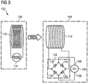
- Fig. 3 shows an example of a wireless charging system 102 not falling under the scope of protection.
- the wireless charging system 102 in Fig. 3 may include a power source 106 for generating electromagnetic waves and the hearing aid 104 for receiving the electromagnetic waves so as to allow wireless charging of the battery 130.
- the hearing aid 104 in Fig. 3 may include a set of battery charging terminals 108 configured to be connected to the battery 130, a receiver oscillator circuit 110 electrically coupled to the set of battery charging terminals 108, and a rectifying circuit 128 electrically coupled to an output of the receiver oscillator circuit 110.
- the rectifying circuit 128 may be a bridge rectifier, which may include four diodes 134.
- the power source 106 for generating the electromagnetic waves of the frequency similar to the resonance frequency of the receiver coil 112 may include a transmitter oscillator circuit 118 electrically coupled to a driving source 120.
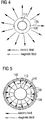
- Fig. 4 shows a cross-sectional view of a receiver coil 112 useful for understanding the invention.
- Fig. 4 shows the electric field(s) 136 and the magnetic field(s) 138 generated when the receiver coil 112 receive the magnetic energy in the form of electromagnetic waves of a frequency similar to the resonance frequency of the receiver coil 112.
- the electric field(s) 136 radiate in an outward direction from the receiver coil 112 and the magnetic field(s) 138 radiate in a circular direction enclosing the receiver coil 112.
- the number of the electric field(s) 136 and magnetic field(s) 138 as shown may not be limited to the number as shown.
- Fig. 5 shows a cross-sectional view of a receiver coil 112 surrounded by a coating 142 useful for understanding the invention.
- Fig. 5 may also show the electric field(s) 136 and the magnetic field(s) 138 generated when the receiver coil 112 receive the magnetic energy in the form of electromagnetic waves of a frequency similar to the resonance frequency of the receiver coil 112.
- the electric field(s) 136 radiate in an outward direction from the receiver coil 112 and the magnetic field(s) 138 radiate in a circular direction enclosing the receiver coil 112.
- the coating 142 may prevent the electric field(s) 136 to radiate into free space but more so induce a further magnetic field(s) 140 (in an opposite direction to the magnetic field(s) 138) inside the coating 142.
- the coating 142 may be highly permeable, no magnetic field (s) (radiation) or further magnetic field(s) 140 may exit the coating 142 but the magnetic field (s) or the further magnetic field(s) 140 may stay inside the coating 142.
- the technical side effect of the coil with the coating 142 may be that by using a full coating 142, the further magnetic field(s) 140 may induce a further electric field(s) (not shown) within the coating 142.
- Fig. 6 shows a perspective view of receiver coil 112 partially surrounded by a coating 142.
- a gap 144 or an opening may be inserted at some point of the receiver coil 112.
- the gap 144 may be dimensioned and arranged to prevent the electrical current from generating a further magnetic field (not shown) which may further generate the further electric field within the coating 142.
- Fig. 7 shows a perspective view of the receiver coil 112 in Fig. 6 surrounding a battery 130 according to an embodiment.
- the receiver coil 112 may surround the battery 130 and the receiver coil 112 may be partially surrounded by the coating 142.
- the coating 142 may also include a gap 144 dimensioned and arranged to prevent the electrical current from generating a magnetic field (not shown) which may further generate a further electrical current (not shown).
- Fig. 8 shows a three-dimensional (3D) perspective view of a battery 130 surrounded by a receiver coil 112 in a left side hearing aid 104 according to an embodiment.
- the receiver coil 112 may surround the battery 130 and the receiver coil 112 may be partially surrounded by the coating 142.
- the coating 142 may also include a gap 144 dimensioned and arranged to prevent the electrical current from generating a magnetic field (not shown) which may further generate a further electric field (not shown) within the coating 142.
- Fig. 9 shows a three-dimensional perspective view of a battery 130 surrounded by a receiver coil 112 in a right side hearing aid 104 according to an embodiment.
- the battery 130 and the receiver coil 112 as shown in Fig. 9 may be different from that as shown in Fig. 8 in that the battery 130 and the receiver coil 112 as shown in Fig 8 may be used in the left side hearing aid 104 and the battery 130 and the receiver coil 112 as shown in Fig. 9 may be used in the right side hearing aid 104.
- Fig. 10 shows a three-dimensional enlarged perspective view of a battery 130 surrounded by a receiver coil 112 as shown in Fig. 9 according to an embodiment.
- Fig. 11 shows a top view of a battery 130 surrounded by a receiver coil 112 in a hearing aid 104 according to an embodiment.
- Fig. 12 shows a perspective view of a behind-the-ear (BTE) hearing aid 104 including a battery 130 surrounded by a receiver coil 112 according to an embodiment.
- the BTE hearing aid 104 further include a PCB 146 on which the rectifying circuit (now shown), the loading circuit (not shown) or the electronic component(s) (not shown) may be arranged on.
- Fig. 13 shows a perspective view of an in-the-ear (ITE) hearing aid 104 including a battery 130 surrounded by a receiver coil 112 according to an embodiment.
- the ITE hearing aid 104 further include a PCB 146 on which the rectifying circuit (now shown), the loading circuit (not shown) or the electronic component(s) (not shown) may be arranged on.
Landscapes
- Engineering & Computer Science (AREA)
- Computer Networks & Wireless Communication (AREA)
- Power Engineering (AREA)
- Health & Medical Sciences (AREA)
- General Health & Medical Sciences (AREA)
- Neurosurgery (AREA)
- Otolaryngology (AREA)
- Physics & Mathematics (AREA)
- Acoustics & Sound (AREA)
- Signal Processing (AREA)
- Charge And Discharge Circuits For Batteries Or The Like (AREA)
Claims (13)
- Aide auditive (104), comportant :un ensemble de bornes de charge de batterie (108) configuré pour être relié à une batterie (130) ;un circuit oscillateur récepteur (110) couplé électriquement à l'ensemble de bornes de charge de batterie (108) ; le circuit oscillateur récepteur (110) comportant une bobine réceptrice (112) ;dans laquelle la bobine réceptrice (112) est accordée pour résonner à une fréquence de résonance dans une plage de radiofréquences et à la fréquence de résonance, la bobine réceptrice (112) est configurée pour recevoir une énergie magnétique sous la forme d'ondes électromagnétiques d'une fréquence similaire à la fréquence de résonance de la bobine réceptrice (112) et pour convertir l'énergie magnétique des ondes électromagnétiques reçues en courant électrique pour charger la batterie (130) par l'intermédiaire de l'ensemble de bornes de charge de batterie (108) ;dans laquelle la bobine réceptrice (112) est positionnée de sorte que la bobine réceptrice (112) entoure la batterie (130).
- Aide auditive (104) selon la revendication 1, comportant en outre
un boîtier de logement de batterie, dans lequel la bobine réceptrice (112) est positionnée dans le boîtier de logement de batterie. - Aide auditive (104) selon la revendication 1 ou 2,
dans laquelle le circuit oscillateur récepteur (110) comporte en outre une résistance réceptrice (114). - Aide auditive (104) selon l'une quelconque des revendications 1 à 3,
dans laquelle le circuit oscillateur récepteur (110) comporte en outre un condensateur récepteur (116), le condensateur récepteur (116) est variable de manière à accorder la bobine réceptrice (112) pour résonner à la fréquence de résonance. - Aide auditive (104) selon l'une quelconque des revendications 1 à 4, comportant en outre
un circuit de rectification (128) couplé électriquement à une sortie du circuit oscillateur récepteur (110). - Aide auditive (104) selon la revendication 5,
dans laquelle le circuit de rectification (128) est configuré pour recevoir un signal de courant alternatif depuis le circuit oscillateur récepteur (110) et pour convertir le signal de courant alternatif en un signal de courant continu à délivrer à la batterie (130). - Aide auditive (104) selon l'une quelconque des revendications 1 à 6,
comportant en outre un circuit de charge (132), le circuit de charge (132) étant couplé électriquement à l'ensemble de bornes de charge de batterie (108). - Aide auditive (104) selon la revendication 7,
dans laquelle le circuit de charge (132) comporte un composant électrique sélectionné parmi un groupe constitué d'un microphone, d'un circuit de traitement de signal, d'un haut-parleur et d'un contrôle de volume. - Aide auditive (104) selon l'une quelconque des revendications 1 à 8,
comportant en outre un revêtement (142), le revêtement (142) étant configuré pour entourer partiellement la bobine réceptrice (112). - Aide auditive (104) selon la revendication 9,
dans laquelle le revêtement (142) comporte un intervalle (144) dimensionné et agencé pour empêcher le courant électrique de générer un autre champ magnétique qui générerait en outre un autre champ électrique. - Aide auditive (104) selon la revendication 9 ou 10,
dans laquelle le revêtement (142) comporte un matériau perméable. - Aide auditive (104) selon l'une quelconque des revendications 9 à 11,
dans laquelle le revêtement (142) comporte un tuyau flexible. - Aide auditive (104) selon l'une quelconque des revendications 1 à 12,
dans laquelle l'aide auditive (104) est une aide auditive contour d'oreille, une aide auditive intra conque, une aide auditive intra conduit ou une aide auditive intra auriculaire.
Applications Claiming Priority (1)
| Application Number | Priority Date | Filing Date | Title |
|---|---|---|---|
| PCT/SG2009/000322 WO2011031233A1 (fr) | 2009-09-08 | 2009-09-08 | Prothèse auditive à capacité de chargement avec batterie sans fil |
Publications (3)
| Publication Number | Publication Date |
|---|---|
| EP2476266A1 EP2476266A1 (fr) | 2012-07-18 |
| EP2476266A4 EP2476266A4 (fr) | 2013-03-13 |
| EP2476266B1 true EP2476266B1 (fr) | 2016-07-06 |
Family
ID=43732693
Family Applications (1)
| Application Number | Title | Priority Date | Filing Date |
|---|---|---|---|
| EP09849310.9A Active EP2476266B1 (fr) | 2009-09-08 | 2009-09-08 | Prothèse auditive à capacité de charger de manière sans fil une batterie |
Country Status (5)
| Country | Link |
|---|---|
| US (1) | US8644542B2 (fr) |
| EP (1) | EP2476266B1 (fr) |
| CN (1) | CN202799146U (fr) |
| DK (1) | DK2476266T3 (fr) |
| WO (1) | WO2011031233A1 (fr) |
Families Citing this family (36)
| Publication number | Priority date | Publication date | Assignee | Title |
|---|---|---|---|---|
| CN103283262B (zh) * | 2010-10-19 | 2016-05-04 | 索诺瓦公司 | 包括可再充电电源的助听器 |
| US20140176060A1 (en) * | 2012-07-02 | 2014-06-26 | Resonate Industries, Inc. | Miniature Low-Power Remote Battery Charging Systems and Methods |
| US9973023B2 (en) | 2012-11-29 | 2018-05-15 | Provenance Asset Group Llc | Inductive energy transfer coil structure |
| JP6513895B2 (ja) * | 2013-02-20 | 2019-05-15 | 日東電工株式会社 | 携帯機器及びその充電機器、携帯機器充電システム |
| KR102000513B1 (ko) | 2013-04-16 | 2019-07-17 | 삼성전자주식회사 | 동작 모드의 스위칭이 가능한 코일을 포함하는 청각 기기 |
| JP6159610B2 (ja) * | 2013-07-19 | 2017-07-05 | 日東電工株式会社 | 回路基板及びそれを備えた携帯機器 |
| JP6604708B2 (ja) * | 2013-10-02 | 2019-11-13 | 日東電工株式会社 | 補聴器 |
| JP6502649B2 (ja) * | 2013-11-12 | 2019-04-17 | ジーエヌ ヒアリング エー/エスGN Hearing A/S | 補聴器用バッテリアセンブリ及び関連する方法 |
| JP2015159664A (ja) * | 2014-02-24 | 2015-09-03 | 日東電工株式会社 | 携帯機器用電源装置及びその充電装置 |
| US9812788B2 (en) | 2014-11-24 | 2017-11-07 | Nxp B.V. | Electromagnetic field induction for inter-body and transverse body communication |
| US10014578B2 (en) | 2014-05-05 | 2018-07-03 | Nxp B.V. | Body antenna system |
| US10009069B2 (en) * | 2014-05-05 | 2018-06-26 | Nxp B.V. | Wireless power delivery and data link |
| US9819395B2 (en) | 2014-05-05 | 2017-11-14 | Nxp B.V. | Apparatus and method for wireless body communication |
| US10015604B2 (en) | 2014-05-05 | 2018-07-03 | Nxp B.V. | Electromagnetic induction field communication |
| US9819075B2 (en) | 2014-05-05 | 2017-11-14 | Nxp B.V. | Body communication antenna |
| DE102015203536B4 (de) * | 2015-02-27 | 2019-08-29 | Sivantos Pte. Ltd. | Mobiler kontaktloser Ladeadapter |
| CN104799971A (zh) * | 2015-04-28 | 2015-07-29 | 张景 | 无线供电并电量提醒的植入式助听装置 |
| US9661426B2 (en) * | 2015-06-22 | 2017-05-23 | Gn Hearing A/S | Hearing aid having combined antennas |
| CA2901210A1 (fr) * | 2015-08-24 | 2017-02-24 | Vladimir Ponomarev | Dispositif d'aide auditive rechargeable |
| US9819097B2 (en) | 2015-08-26 | 2017-11-14 | Nxp B.V. | Antenna system |
| CA2903680A1 (fr) * | 2015-09-11 | 2017-03-11 | Vladimir Ponomarev | Dispositif d'aide auditive |
| US10320086B2 (en) | 2016-05-04 | 2019-06-11 | Nxp B.V. | Near-field electromagnetic induction (NFEMI) antenna |
| US11206499B2 (en) | 2016-08-18 | 2021-12-21 | Qualcomm Incorporated | Hearable device comprising integrated device and wireless functionality |
| US20190052979A1 (en) * | 2017-01-05 | 2019-02-14 | Ohio State Innovation Foundation | Systems and methods for wirelessly charging a hearing device |
| JP6929732B2 (ja) * | 2017-03-31 | 2021-09-01 | 日東電工株式会社 | 電池パック、無線電力伝送システムおよび補聴器 |
| DE102017209813B3 (de) * | 2017-06-09 | 2018-09-06 | Sivantos Pte. Ltd. | Hörgerät, insbesondere Hinter-dem-Ohr-Hörhilfegerät |
| KR102075779B1 (ko) * | 2017-08-18 | 2020-02-11 | 주식회사 아모텍 | 링형 안테나 및 이를 구비한 이어 모듈 |
| EP3682650B1 (fr) * | 2017-09-15 | 2025-04-30 | GN Hearing A/S | Procédé pour charge inductive d'un instrument auditif rechargeable |
| US10356537B2 (en) * | 2017-12-01 | 2019-07-16 | Semiconductor Components Industries, Llc | All-in-one method for wireless connectivity and contactless battery charging of small wearables |
| DE102018209189A1 (de) * | 2018-06-08 | 2019-12-12 | Sivantos Pte. Ltd. | Antenne sowie Gerät mit einer solchen Antenne |
| EP3588974A3 (fr) * | 2018-06-22 | 2020-01-22 | Sivantos Pte. Ltd. | Procédé pour charger un dispositif auditif, système de dispositif auditif, dispositif auditif et unité de chargement |
| EP3831095A4 (fr) * | 2018-07-31 | 2022-06-08 | Earlens Corporation | Couplage inductif en champ proche dans un système auditif à contact |
| CN110149583A (zh) * | 2019-05-27 | 2019-08-20 | 深圳市中德听力技术有限公司 | 一种无线充电助听器 |
| US11606648B2 (en) * | 2020-01-31 | 2023-03-14 | Oticon Medical A/S | Charging and updating of an implantable hearing aid |
| EP4152765A1 (fr) * | 2021-09-15 | 2023-03-22 | GN Hearing A/S | Dispositif auditif rechargeable sans fil |
| US12407971B2 (en) * | 2021-09-30 | 2025-09-02 | Starkey Laboratories, Inc. | Ear-wearable electronic device including multi-function removal handle |
Family Cites Families (9)
| Publication number | Priority date | Publication date | Assignee | Title |
|---|---|---|---|---|
| US4379988A (en) * | 1981-01-19 | 1983-04-12 | Patricio Mattatall | Molded hearing aid and battery charger |
| DE3633722C1 (de) | 1986-10-03 | 1987-11-12 | Borowsky Hans Dieter | Drahtlose Ladeschaltung fuer Hoergeraete |
| JPH1140207A (ja) | 1997-07-22 | 1999-02-12 | Sanyo Electric Co Ltd | パック電池と充電台 |
| US6265100B1 (en) * | 1998-02-23 | 2001-07-24 | Research International, Inc. | Rechargeable battery |
| US6658124B1 (en) * | 2000-04-06 | 2003-12-02 | Advanced Bionics Corporation | Rechargeable hearing aid |
| US6498455B2 (en) * | 2001-02-22 | 2002-12-24 | Gary Skuro | Wireless battery charging system for existing hearing aids using a dynamic battery and a charging processor unit |
| US7620195B2 (en) * | 2005-11-09 | 2009-11-17 | Zounds, Inc. | Rechargeable hearing aid |
| US8169185B2 (en) | 2006-01-31 | 2012-05-01 | Mojo Mobility, Inc. | System and method for inductive charging of portable devices |
| DE102007009176A1 (de) | 2007-02-26 | 2008-09-04 | Siemens Audiologische Technik Gmbh | Hörvorrichtung mit einem speziellen Energieaufnahmesystem und entsprechendes Verfahren |
-
2009
- 2009-09-08 WO PCT/SG2009/000322 patent/WO2011031233A1/fr not_active Ceased
- 2009-09-08 DK DK09849310.9T patent/DK2476266T3/en active
- 2009-09-08 CN CN2009901007867U patent/CN202799146U/zh not_active Expired - Lifetime
- 2009-09-08 EP EP09849310.9A patent/EP2476266B1/fr active Active
- 2009-09-08 US US13/394,867 patent/US8644542B2/en active Active
Also Published As
| Publication number | Publication date |
|---|---|
| WO2011031233A1 (fr) | 2011-03-17 |
| CN202799146U (zh) | 2013-03-13 |
| EP2476266A1 (fr) | 2012-07-18 |
| EP2476266A4 (fr) | 2013-03-13 |
| DK2476266T3 (en) | 2016-10-24 |
| US20120170781A1 (en) | 2012-07-05 |
| US8644542B2 (en) | 2014-02-04 |
Similar Documents
| Publication | Publication Date | Title |
|---|---|---|
| EP2476266B1 (fr) | Prothèse auditive à capacité de charger de manière sans fil une batterie | |
| EP2285138B1 (fr) | Appareil auditif equipé d'une antenne destinée à l'emission et à la reception de signaux électromagnétiques | |
| US10777892B2 (en) | Antenna | |
| US7990103B2 (en) | Portable electronic apparatus, and battery charging system comprising an antenna arrangement for a radio receiver | |
| EP3588790B1 (fr) | Antenne et dispositifs à induction électromagnétique en champ proche (nfemi) | |
| US20160149437A1 (en) | Laptop computer as a transmitter for wireless charging | |
| CN106486778A (zh) | 天线系统 | |
| KR20140147650A (ko) | 전자 장치의 무선 충전 시스템 | |
| KR101744590B1 (ko) | 수직형 전력 전송 방식의 무선 전력 전송 및 충전 장치 | |
| CN110012404A (zh) | 包括电池天线的听力仪器 | |
| US20080170733A1 (en) | Charging device for a hearing aid, hearing aid and hearing aid remote control | |
| CN109996164A (zh) | 包括寄生电池天线元件的听力仪器 | |
| CN216122893U (zh) | 电池模块和听力装置 | |
| US20170149268A1 (en) | Communication device | |
| WO2018179902A1 (fr) | Système de transmission d'énergie sans contact et aide auditive | |
| KR20210155379A (ko) | 무선 전력 수신 및 유선 전력 송신 장치 | |
| GB2584814A (en) | Multiband wireless charging apparatus | |
| WO2017031583A1 (fr) | Système d'aide auditive rechargeable |
Legal Events
| Date | Code | Title | Description |
|---|---|---|---|
| PUAI | Public reference made under article 153(3) epc to a published international application that has entered the european phase |
Free format text: ORIGINAL CODE: 0009012 |
|
| 17P | Request for examination filed |
Effective date: 20120301 |
|
| AK | Designated contracting states |
Kind code of ref document: A1 Designated state(s): AT BE BG CH CY CZ DE DK EE ES FI FR GB GR HR HU IE IS IT LI LT LU LV MC MK MT NL NO PL PT RO SE SI SK SM TR |
|
| DAX | Request for extension of the european patent (deleted) | ||
| DAX | Request for extension of the european patent (deleted) | ||
| A4 | Supplementary search report drawn up and despatched |
Effective date: 20130211 |
|
| RIC1 | Information provided on ipc code assigned before grant |
Ipc: H04R 25/00 20060101AFI20130205BHEP Ipc: H02J 7/02 20060101ALI20130205BHEP |
|
| 17Q | First examination report despatched |
Effective date: 20131028 |
|
| GRAP | Despatch of communication of intention to grant a patent |
Free format text: ORIGINAL CODE: EPIDOSNIGR1 |
|
| DAX | Request for extension of the european patent (deleted) | ||
| INTG | Intention to grant announced |
Effective date: 20150428 |
|
| RAP1 | Party data changed (applicant data changed or rights of an application transferred) |
Owner name: SIVANTOS PTE. LTD. |
|
| GRAS | Grant fee paid |
Free format text: ORIGINAL CODE: EPIDOSNIGR3 |
|
| INTG | Intention to grant announced |
Effective date: 20160204 |
|
| GRAA | (expected) grant |
Free format text: ORIGINAL CODE: 0009210 |
|
| AK | Designated contracting states |
Kind code of ref document: B1 Designated state(s): AT BE BG CH CY CZ DE DK EE ES FI FR GB GR HR HU IE IS IT LI LT LU LV MC MK MT NL NO PL PT RO SE SI SK SM TR |
|
| REG | Reference to a national code |
Ref country code: GB Ref legal event code: FG4D |
|
| REG | Reference to a national code |
Ref country code: AT Ref legal event code: REF Ref document number: 811440 Country of ref document: AT Kind code of ref document: T Effective date: 20160715 Ref country code: CH Ref legal event code: EP |
|
| REG | Reference to a national code |
Ref country code: IE Ref legal event code: FG4D |
|
| REG | Reference to a national code |
Ref country code: CH Ref legal event code: NV Representative=s name: E. BLUM AND CO. AG PATENT- UND MARKENANWAELTE , CH |
|
| REG | Reference to a national code |
Ref country code: DE Ref legal event code: R096 Ref document number: 602009039658 Country of ref document: DE |
|
| REG | Reference to a national code |
Ref country code: FR Ref legal event code: PLFP Year of fee payment: 8 |
|
| REG | Reference to a national code |
Ref country code: DK Ref legal event code: T3 Effective date: 20161021 |
|
| REG | Reference to a national code |
Ref country code: NL Ref legal event code: MP Effective date: 20160706 |
|
| REG | Reference to a national code |
Ref country code: LT Ref legal event code: MG4D |
|
| REG | Reference to a national code |
Ref country code: AT Ref legal event code: MK05 Ref document number: 811440 Country of ref document: AT Kind code of ref document: T Effective date: 20160706 |
|
| PG25 | Lapsed in a contracting state [announced via postgrant information from national office to epo] |
Ref country code: LT Free format text: LAPSE BECAUSE OF FAILURE TO SUBMIT A TRANSLATION OF THE DESCRIPTION OR TO PAY THE FEE WITHIN THE PRESCRIBED TIME-LIMIT Effective date: 20160706 Ref country code: IT Free format text: LAPSE BECAUSE OF FAILURE TO SUBMIT A TRANSLATION OF THE DESCRIPTION OR TO PAY THE FEE WITHIN THE PRESCRIBED TIME-LIMIT Effective date: 20160706 Ref country code: HR Free format text: LAPSE BECAUSE OF FAILURE TO SUBMIT A TRANSLATION OF THE DESCRIPTION OR TO PAY THE FEE WITHIN THE PRESCRIBED TIME-LIMIT Effective date: 20160706 Ref country code: NO Free format text: LAPSE BECAUSE OF FAILURE TO SUBMIT A TRANSLATION OF THE DESCRIPTION OR TO PAY THE FEE WITHIN THE PRESCRIBED TIME-LIMIT Effective date: 20161006 Ref country code: FI Free format text: LAPSE BECAUSE OF FAILURE TO SUBMIT A TRANSLATION OF THE DESCRIPTION OR TO PAY THE FEE WITHIN THE PRESCRIBED TIME-LIMIT Effective date: 20160706 Ref country code: IS Free format text: LAPSE BECAUSE OF FAILURE TO SUBMIT A TRANSLATION OF THE DESCRIPTION OR TO PAY THE FEE WITHIN THE PRESCRIBED TIME-LIMIT Effective date: 20161106 Ref country code: NL Free format text: LAPSE BECAUSE OF FAILURE TO SUBMIT A TRANSLATION OF THE DESCRIPTION OR TO PAY THE FEE WITHIN THE PRESCRIBED TIME-LIMIT Effective date: 20160706 |
|
| PG25 | Lapsed in a contracting state [announced via postgrant information from national office to epo] |
Ref country code: ES Free format text: LAPSE BECAUSE OF FAILURE TO SUBMIT A TRANSLATION OF THE DESCRIPTION OR TO PAY THE FEE WITHIN THE PRESCRIBED TIME-LIMIT Effective date: 20160706 Ref country code: LV Free format text: LAPSE BECAUSE OF FAILURE TO SUBMIT A TRANSLATION OF THE DESCRIPTION OR TO PAY THE FEE WITHIN THE PRESCRIBED TIME-LIMIT Effective date: 20160706 Ref country code: PT Free format text: LAPSE BECAUSE OF FAILURE TO SUBMIT A TRANSLATION OF THE DESCRIPTION OR TO PAY THE FEE WITHIN THE PRESCRIBED TIME-LIMIT Effective date: 20161107 Ref country code: PL Free format text: LAPSE BECAUSE OF FAILURE TO SUBMIT A TRANSLATION OF THE DESCRIPTION OR TO PAY THE FEE WITHIN THE PRESCRIBED TIME-LIMIT Effective date: 20160706 Ref country code: SE Free format text: LAPSE BECAUSE OF FAILURE TO SUBMIT A TRANSLATION OF THE DESCRIPTION OR TO PAY THE FEE WITHIN THE PRESCRIBED TIME-LIMIT Effective date: 20160706 Ref country code: AT Free format text: LAPSE BECAUSE OF FAILURE TO SUBMIT A TRANSLATION OF THE DESCRIPTION OR TO PAY THE FEE WITHIN THE PRESCRIBED TIME-LIMIT Effective date: 20160706 Ref country code: BE Free format text: LAPSE BECAUSE OF NON-PAYMENT OF DUE FEES Effective date: 20160706 Ref country code: GR Free format text: LAPSE BECAUSE OF FAILURE TO SUBMIT A TRANSLATION OF THE DESCRIPTION OR TO PAY THE FEE WITHIN THE PRESCRIBED TIME-LIMIT Effective date: 20161007 |
|
| REG | Reference to a national code |
Ref country code: DE Ref legal event code: R097 Ref document number: 602009039658 Country of ref document: DE |
|
| PG25 | Lapsed in a contracting state [announced via postgrant information from national office to epo] |
Ref country code: RO Free format text: LAPSE BECAUSE OF FAILURE TO SUBMIT A TRANSLATION OF THE DESCRIPTION OR TO PAY THE FEE WITHIN THE PRESCRIBED TIME-LIMIT Effective date: 20160706 Ref country code: MC Free format text: LAPSE BECAUSE OF FAILURE TO SUBMIT A TRANSLATION OF THE DESCRIPTION OR TO PAY THE FEE WITHIN THE PRESCRIBED TIME-LIMIT Effective date: 20160706 Ref country code: EE Free format text: LAPSE BECAUSE OF FAILURE TO SUBMIT A TRANSLATION OF THE DESCRIPTION OR TO PAY THE FEE WITHIN THE PRESCRIBED TIME-LIMIT Effective date: 20160706 |
|
| PLBE | No opposition filed within time limit |
Free format text: ORIGINAL CODE: 0009261 |
|
| STAA | Information on the status of an ep patent application or granted ep patent |
Free format text: STATUS: NO OPPOSITION FILED WITHIN TIME LIMIT |
|
| PG25 | Lapsed in a contracting state [announced via postgrant information from national office to epo] |
Ref country code: BG Free format text: LAPSE BECAUSE OF FAILURE TO SUBMIT A TRANSLATION OF THE DESCRIPTION OR TO PAY THE FEE WITHIN THE PRESCRIBED TIME-LIMIT Effective date: 20161006 Ref country code: SK Free format text: LAPSE BECAUSE OF FAILURE TO SUBMIT A TRANSLATION OF THE DESCRIPTION OR TO PAY THE FEE WITHIN THE PRESCRIBED TIME-LIMIT Effective date: 20160706 Ref country code: CZ Free format text: LAPSE BECAUSE OF FAILURE TO SUBMIT A TRANSLATION OF THE DESCRIPTION OR TO PAY THE FEE WITHIN THE PRESCRIBED TIME-LIMIT Effective date: 20160706 Ref country code: SM Free format text: LAPSE BECAUSE OF FAILURE TO SUBMIT A TRANSLATION OF THE DESCRIPTION OR TO PAY THE FEE WITHIN THE PRESCRIBED TIME-LIMIT Effective date: 20160706 |
|
| 26N | No opposition filed |
Effective date: 20170407 |
|
| REG | Reference to a national code |
Ref country code: IE Ref legal event code: MM4A |
|
| PG25 | Lapsed in a contracting state [announced via postgrant information from national office to epo] |
Ref country code: IE Free format text: LAPSE BECAUSE OF NON-PAYMENT OF DUE FEES Effective date: 20160908 |
|
| PG25 | Lapsed in a contracting state [announced via postgrant information from national office to epo] |
Ref country code: SI Free format text: LAPSE BECAUSE OF FAILURE TO SUBMIT A TRANSLATION OF THE DESCRIPTION OR TO PAY THE FEE WITHIN THE PRESCRIBED TIME-LIMIT Effective date: 20160706 Ref country code: LU Free format text: LAPSE BECAUSE OF NON-PAYMENT OF DUE FEES Effective date: 20160908 |
|
| REG | Reference to a national code |
Ref country code: FR Ref legal event code: PLFP Year of fee payment: 9 |
|
| PG25 | Lapsed in a contracting state [announced via postgrant information from national office to epo] |
Ref country code: CY Free format text: LAPSE BECAUSE OF FAILURE TO SUBMIT A TRANSLATION OF THE DESCRIPTION OR TO PAY THE FEE WITHIN THE PRESCRIBED TIME-LIMIT Effective date: 20160706 Ref country code: HU Free format text: LAPSE BECAUSE OF FAILURE TO SUBMIT A TRANSLATION OF THE DESCRIPTION OR TO PAY THE FEE WITHIN THE PRESCRIBED TIME-LIMIT; INVALID AB INITIO Effective date: 20090908 |
|
| PG25 | Lapsed in a contracting state [announced via postgrant information from national office to epo] |
Ref country code: TR Free format text: LAPSE BECAUSE OF FAILURE TO SUBMIT A TRANSLATION OF THE DESCRIPTION OR TO PAY THE FEE WITHIN THE PRESCRIBED TIME-LIMIT Effective date: 20160706 Ref country code: MK Free format text: LAPSE BECAUSE OF FAILURE TO SUBMIT A TRANSLATION OF THE DESCRIPTION OR TO PAY THE FEE WITHIN THE PRESCRIBED TIME-LIMIT Effective date: 20160706 Ref country code: MT Free format text: LAPSE BECAUSE OF NON-PAYMENT OF DUE FEES Effective date: 20160930 |
|
| REG | Reference to a national code |
Ref country code: FR Ref legal event code: PLFP Year of fee payment: 10 |
|
| REG | Reference to a national code |
Ref country code: CH Ref legal event code: U11 Free format text: ST27 STATUS EVENT CODE: U-0-0-U10-U11 (AS PROVIDED BY THE NATIONAL OFFICE) Effective date: 20251001 |
|
| PGFP | Annual fee paid to national office [announced via postgrant information from national office to epo] |
Ref country code: DK Payment date: 20250820 Year of fee payment: 17 Ref country code: DE Payment date: 20250820 Year of fee payment: 17 |
|
| PGFP | Annual fee paid to national office [announced via postgrant information from national office to epo] |
Ref country code: GB Payment date: 20250822 Year of fee payment: 17 |
|
| PGFP | Annual fee paid to national office [announced via postgrant information from national office to epo] |
Ref country code: FR Payment date: 20250820 Year of fee payment: 17 |
|
| PGFP | Annual fee paid to national office [announced via postgrant information from national office to epo] |
Ref country code: CH Payment date: 20251001 Year of fee payment: 17 |