EP2476323B1 - Röstvorrichtung - Google Patents
Röstvorrichtung Download PDFInfo
- Publication number
- EP2476323B1 EP2476323B1 EP20110150821 EP11150821A EP2476323B1 EP 2476323 B1 EP2476323 B1 EP 2476323B1 EP 20110150821 EP20110150821 EP 20110150821 EP 11150821 A EP11150821 A EP 11150821A EP 2476323 B1 EP2476323 B1 EP 2476323B1
- Authority
- EP
- European Patent Office
- Prior art keywords
- opening
- holes
- chamber
- hole
- roasting
- Prior art date
- Legal status (The legal status is an assumption and is not a legal conclusion. Google has not performed a legal analysis and makes no representation as to the accuracy of the status listed.)
- Active
Links
Images

Classifications
-
- A—HUMAN NECESSITIES
- A23—FOODS OR FOODSTUFFS; TREATMENT THEREOF, NOT COVERED BY OTHER CLASSES
- A23N—MACHINES OR APPARATUS FOR TREATING HARVESTED FRUIT, VEGETABLES OR FLOWER BULBS IN BULK, NOT OTHERWISE PROVIDED FOR; PEELING VEGETABLES OR FRUIT IN BULK; APPARATUS FOR PREPARING ANIMAL FEEDING- STUFFS
- A23N12/00—Machines for cleaning, blanching, drying or roasting fruits or vegetables, e.g. coffee, cocoa, nuts
- A23N12/08—Machines for cleaning, blanching, drying or roasting fruits or vegetables, e.g. coffee, cocoa, nuts for drying or roasting
-
- F—MECHANICAL ENGINEERING; LIGHTING; HEATING; WEAPONS; BLASTING
- F26—DRYING
- F26B—DRYING SOLID MATERIALS OR OBJECTS BY REMOVING LIQUID THEREFROM
- F26B3/00—Drying solid materials or objects by processes involving the application of heat
- F26B3/02—Drying solid materials or objects by processes involving the application of heat by convection, i.e. heat being conveyed from a heat source to the materials or objects to be dried by a gas or vapour, e.g. air
- F26B3/06—Drying solid materials or objects by processes involving the application of heat by convection, i.e. heat being conveyed from a heat source to the materials or objects to be dried by a gas or vapour, e.g. air the gas or vapour flowing through the materials or objects to be dried
- F26B3/08—Drying solid materials or objects by processes involving the application of heat by convection, i.e. heat being conveyed from a heat source to the materials or objects to be dried by a gas or vapour, e.g. air the gas or vapour flowing through the materials or objects to be dried so as to loosen them, e.g. to form a fluidised bed
- F26B3/082—Drying solid materials or objects by processes involving the application of heat by convection, i.e. heat being conveyed from a heat source to the materials or objects to be dried by a gas or vapour, e.g. air the gas or vapour flowing through the materials or objects to be dried so as to loosen them, e.g. to form a fluidised bed arrangements of devices for distributing fluidising gas, e.g. grids, nozzles
-
- F—MECHANICAL ENGINEERING; LIGHTING; HEATING; WEAPONS; BLASTING
- F26—DRYING
- F26B—DRYING SOLID MATERIALS OR OBJECTS BY REMOVING LIQUID THEREFROM
- F26B3/00—Drying solid materials or objects by processes involving the application of heat
- F26B3/02—Drying solid materials or objects by processes involving the application of heat by convection, i.e. heat being conveyed from a heat source to the materials or objects to be dried by a gas or vapour, e.g. air
- F26B3/06—Drying solid materials or objects by processes involving the application of heat by convection, i.e. heat being conveyed from a heat source to the materials or objects to be dried by a gas or vapour, e.g. air the gas or vapour flowing through the materials or objects to be dried
- F26B3/08—Drying solid materials or objects by processes involving the application of heat by convection, i.e. heat being conveyed from a heat source to the materials or objects to be dried by a gas or vapour, e.g. air the gas or vapour flowing through the materials or objects to be dried so as to loosen them, e.g. to form a fluidised bed
- F26B3/092—Drying solid materials or objects by processes involving the application of heat by convection, i.e. heat being conveyed from a heat source to the materials or objects to be dried by a gas or vapour, e.g. air the gas or vapour flowing through the materials or objects to be dried so as to loosen them, e.g. to form a fluidised bed agitating the fluidised bed, e.g. by vibrating or pulsating
- F26B3/0926—Drying solid materials or objects by processes involving the application of heat by convection, i.e. heat being conveyed from a heat source to the materials or objects to be dried by a gas or vapour, e.g. air the gas or vapour flowing through the materials or objects to be dried so as to loosen them, e.g. to form a fluidised bed agitating the fluidised bed, e.g. by vibrating or pulsating by pneumatic means, e.g. spouted beds
Definitions
- the subject of the present invention is a roasting device, in particular for coffee, hazelnuts, or the like, comprising a roasting chamber, which is designed to receive the material to be treated in an accumulation area, and is provided, in said accumulation area, with an opening for inlet of a flow of treatment air against the aforesaid material, said flow being designed to bring into suspension at least one part of said material.
- a device of this type is, for example, described in the U.S. patents No. US4698916 and US3329506 .
- a jet of hot air is projected from beneath upwards within the roasting chamber so as to generate a circulation of coffee beans in suspension.
- the amount of coffee that can be roasted in one and the same cycle depends upon the kinetic energy of the jet of hot air that is introduced into the roasting chamber.
- said jet of hot air must have a kinetic energy sufficient for bringing into suspension the entire amount of coffee to be roasted and effecting the aforementioned circulation of the beans.
- the device described in said patent application envisages, within the roasting chamber, a tubular portion that is designed to define, externally, an area in which the material to be roasted poured into the chamber is gathered, and that, in operation, is designed to intercept the air flow introduced into the chamber so as to generate a circulation of material according to an ascending flow, through said tubular portion, and a descending flow of return to the accumulation area, outside said portion. Thanks to a circulation of material of this sort, said device is able to roast homogeneously and efficiently relatively large amounts of material.
- the object of the present invention is to provide a roasting device that will afford the same advantages that the prior device proposed by the present applicant guarantees - with respect to the conventional technique represented by the document No. US4698916 - and that at the same time will be characterized by a higher efficiency of operation and by faster processing times.
- Said object is achieved via a roasting device having the characteristics of Claim 1.
- the device described herein can do without any tubular element inside the roasting chamber, and generate even so, inside it, a circulation of material similar to the one described above with reference to the device described in the patent application No. T02008A000949 .
- said circulation envisages that, cyclically, part of the material impinged upon by the flow of treatment air is projected upwards, creating an ascending flow of material, and that it then returns, by gravity, into the accumulation area, creating a descending flow, external to the ascending flow indicated above.
- the nozzle element provided in said device is such as to deliver a jet of air that is able to make a hole in the mass of material that overlies it, and project a part thereof (and only a part) upwards.
- the jet generated has a greater impulse in the central area in order to have a greater capacity of penetration of the material.
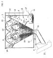
- the roasting device Designated as a whole by the reference number 1 is the roasting device described herein. It comprises a casing 2 defining a top opening through which the material to be treated is poured into the device, a lid 3 being mounted rocking on the casing 2, for closing said opening.
- the lid 3 has a transparent portion 4 through which it is possible to control visually the state of treatment of the material being processed.
- a mouth 5 projecting from a side of the casing 2 constitutes discharge of the treated material.
- the casing 2 is advantageously mounted on swivel wheels 7 to enable easy displacement.
- FIG. 2 is a diagram of principle of the roasting device 1.
- a roasting chamber 8 delimited by a frustoconical wall 9 converging downwards and delimiting a bottom opening 10.
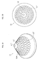
- a nozzle element 11 (illustrated in detail in Figure 3 ) is designed to engage the opening 10.
- Said element has a body designed to close the opening 10, made in which is a plurality of through holes parallel to the axis of said opening.
- the configuration of said body is such that at least one first hole 11' of said plurality, which is located in a first position, has a length greater than at least one second hole 11" of said plurality, which is located in a second position, said second position being more peripheral with respect to said first position.
- the holes provided in the nozzle element 11 have all the same diameter.
- peripheral position is meant a position that is at a given distance from the central geometrical axis of the body of the nozzle element, measured in a plane parallel or coinciding with a plane of section (of the element) that is substantially orthogonal to said axis.
- the overall shape of the body of the nozzle element need not have a circular symmetry, but can instead have all those configurations for which it is possible to define a central region.
- the configuration referred to above enables delivery, within the chamber, of an air flow that is able to make a hole in the mass of material to be roasted accumulated in the chamber, and project a part thereof upwards. Said effect is obtained thanks to the fact that the flow delivered by the element 11 has a central part with higher impulse.
- the aforesaid plurality of through holes is made, on the body of the nozzle element, starting from one and the same plane that is on the side opposite to the one facing the roasting chamber and is substantially orthogonal to the axial direction of the opening 10.
- the aforesaid plurality of holes is made in a first portion and a second portion of the body of the nozzle element, the second portion having a thickness smaller than the first portion and occupying a region more peripheral with respect to the first portion.
- the aforesaid plurality of holes is made in one and the same portion 11A of the body of the nozzle element, which has a thickness increasing towards the centre of the element itself. It is clear that the thickness referred to above is the one measured in the direction along which said holes are made in said portions.
- the aforesaid plurality of holes comprises a plurality of circular series of axial holes, which extend along respective concentric circumferences, and in which the holes of a first circular series are longer than the holes of a second circular series external to the first series (see Figures 3A and 3B ).
- the aforesaid plurality of holes is made in a portion 11A having a general configuration that is substantially conical. Said holes are in particular made in directions substantially parallel to the geometrical axis of the conical shape of the body of the element 11.
- the aforesaid plurality of holes comprises a central hole 11''' having a length greater than that of all the other holes.
- the opening 10 is associated to an air duct 21.
- the end of the duct 21 is closed by the element 11, which is anchored thereto, and said duct is mounted rocking on the fixed structure of the device, between a first raised position (illustrated with a solid line in Figure 2 ), in which the element 11 is brought into engagement with the opening 10, and a second lowered position (illustrated with a dashed line in Figure 2 ), in which the opening 10 is released from the element 11 and the roasted material can be discharged through the opening 10 itself.
- the roasting chamber 8 is delimited at the top by a wall 13 fixed with respect to the lid 3 of the casing 2.
- the wall 13 has a deviator element 13', formed by a central portion with a generic reversed-cone shape, in axis with the element 11, extending from which is a concave wall that surrounds said central portion.
- the element 13' has the function of re-directing the material according to a distribution that is substantially homogeneous in all radial directions of the chamber 8.
- the material to be roasted is introduced into the chamber 8 from the top opening of the casing 2, and accumulates on top of the element 11 engaging with the opening 10.
- the duct 21 is in the raised position.
- the device is actuated, and the jet of treatment air starts to being introduced into the roasting chamber via the nozzle element 11.
- the jet of air delivered by the element 11 makes a hole in the mass of material that overlies the element 11 itself, and projects a part thereof upwards.
- the material projected upwards as a result of the continuous jet of air that comes from beneath, then tends to drop back, passing alongside the ascending flow, towards the area that surrounds the element 11 occupied by the material not intercepted by the jet of air.
- the wall 13 is provided with the deviator element 13' described above, the material is projected against it and re-directed according to a distribution substantially homogeneous in all the radial directions of the chamber 8.
- the absence of the tubular element then means that the thermal energy of the air introduced into the chamber is completely exploited for heating the material, instead of being in part wasted in heating the tubular element, as occurs in the prior device.
- Said aspects mean that the process of operation of the device is as a whole more efficient and faster than that of the prior device indicated above.
- the area up against the walls 9 of the roasting chamber 8 constitutes a sort of tank where the material previously impinged upon by the jet of air accumulates to be again impinged upon by the latter after the underlying material has been processed by the action of the jet of hot air. Thanks to said area of tank, the flow rate of material to be entrained via the jet of air can then be advantageously regulated irrespective of the overall amount of material to be roasted introduced into the roasting chamber. In this way, the roasting process is performed with jets of air of limited power, whatever the amount of material introduced into the chamber.
- a passage 14 is provided in communication with the space comprised between the casing 2 and the roasting chamber 8.
- Said passage 14 enables the waste of the material being processed that is generated during roasting, which is lighter than the material to be roasted, to come out of the chamber 8 and be conveyed via a chute 15 into a drawer 16 that can be taken out of the casing 2, within which it gathers and can then be easily disposed of by an operator.
- a step of cooling of the roasted material is envisaged, obtained by injecting within the chamber 8 a jet of cold air in the same mode described above for the jet of hot air.
- the jets of air injected within the chamber 8 are generated with means of an appropriate type (not illustrated), which are designed to create an air flow and condition it with hot or cold sources of heat, according to the need.
- the air introduced into the chamber 8 then comes out of the casing 2 through an outlet mouth 17, before which a grill 18 is set designed to prevent the waste resulting from the roasting cycle from coming out through said outlet mouth 17.
- the roasting device described above is particularly suited for roasting coffee, hazelnuts, or the like.
Landscapes
- Engineering & Computer Science (AREA)
- Life Sciences & Earth Sciences (AREA)
- Microbiology (AREA)
- Mechanical Engineering (AREA)
- General Engineering & Computer Science (AREA)
- Chemical & Material Sciences (AREA)
- Food Science & Technology (AREA)
- Polymers & Plastics (AREA)
- Apparatuses For Bulk Treatment Of Fruits And Vegetables And Apparatuses For Preparing Feeds (AREA)
- Tea And Coffee (AREA)
Claims (8)
- Röstvorrichtung, insbesondere für Kaffee, Haselnüsse oder Ähnliches, umfassend eine Röstkammer (8), die dazu konzipiert ist, das zu behandelnde Material in einem Sammelbereich (19) aufzunehmen und die in diesem Sammelbereich mit einer Einlassöffnung (10) für einen Strom von Behandlungsluft auf das Material versehen ist, wobei dieser Strom so ausgelegt ist, dass wenigstens ein Teil des Materials in Schwebung versetzt wird,
wobei die Vorrichtung dadurch gekennzeichnet ist, dass sie ein Düsenelement (11) mit einem Körper (11A) umfasst, das dazu eingerichtet ist, die Öffnung (10) durch Drehen in Richtung der Innenseite der Kammer zu schließen, wobei in diesem Körper (11A) eine Vielzahl von Durchgangsöffnungen ausgebildet ist, die im Wesentlichen parallel zur Achse der Öffnung angeordnet sind, wobei der Körper so aufgebaut ist, dass mindestens eine erste Öffnung (11') der Vielzahl, die in einer ersten Position angeordnet ist, eine größere Länge als mindestens eine zweite Öffnung (11") der Vielzahl aufweist, die in einer zweiten Position angeordnet ist, wobei sich die zweite Position bezüglich der ersten Position weiter am Rand befindet, wobei die erste und zweite Öffnung in ein und demselben Teil (11A) des Körpers ausgebildet sind, der eine Dicke aufweist, die in Richtung der Mitte des Elements zunimmt, und wobei sich die zweite Öffnung weiter am Rand befindet als die erste Öffnung. - Vorrichtung nach Anspruch 1, dadurch gekennzeichnet, dass die Vielzahl von Öffnungen in dem Körper des Düsenelements beginnend in ein und derselben Ebene des Körpers ausgebildet sind, die sich auf der Seite gegenüber derjenigen Seite befindet, die der Röstkammer zugewandet ist und die im Wesentlichen orthogonal zu der axialen Richtung der Öffnung (10) verläuft.
- Vorrichtung nach einem der vorhergehenden Ansprüche, dadurch gekennzeichnet, dass die Vielzahl der Öffnungen eine Vielzahl an kreisförmigen Reihen von axialen Öffnungen umfasst, die sich jeweils entlang konzentrischen Kreisumfängen erstrecken, und dadurch, dass eine erste kreisförmige Reihe eine Vielzahl der mindestens einen ersten Öffnungen umfasst und eine zweite kreisförmige Reihe außerhalb der ersten Reihe eine Vielzahl der mindestens einen zweiten Öffnungen umfasst.
- Vorrichtung nach einem der vorhergehenden Ansprüche, dadurch gekennzeichnet, dass die Vielzahl der Öffnungen in einem Teil (11A) des Körpers ausgebildet ist, der einen allgemeinen Aufbau aufweist, der im Wesentlichen konisch ist.
- Vorrichtung nach einem der vorhergehenden Ansprüche, dadurch gekennzeichnet, dass die Vielzahl der Öffnungen eine mittlere Öffnung (11"') mit einer Länge umfasst, die größer als die aller anderen Öffnungen ist.
- Vorrichtung nach einem der vorhergehenden Ansprüche, dadurch gekennzeichnet, dass die Röstkammer Seitenwände (9) aufweist, die in Richtung der Einlassöffnung für den Luftstrom zusammenlaufen.
- Vorrichtung nach einem der vorhergehenden Ansprüche, dadurch gekennzeichnet, dass an der Wand der Kammer gegenüber der Einlassöffnung eine Wand (13) angeordnet und dazu eingerichtet ist, während des Betriebs aus dem röhrenförmigen Abschnitt kommendes Material zurückzustoßen, wobei diese Wand ein Deviatorelement (13') aufweist, das dazu eingerichtet ist, das Material in radiale Positionen der Kammer außerhalb der Öffnung zu leiten.
- Vorrichtung nach einem der vorhergehenden Ansprüche, dadurch gekennzeichnet, dass das Düsenelement am Ende des Kanals befestigt ist, der die Luft zu der Öffnung leitet, wobei der Kanal (21) so an der festen Struktur der Vorrichtung montiert ist, dass er sich zwischen einer angehobenen Position, in der das Düsenelement (11) in Eingriff mit der Öffnung (10) kommt und einer zweiten abgesenkten Position hin- und herbewegt, in der die Öffnung (10) von dem Düsenelement (11) getrennt ist und das geröstete Material durch die Öffnung abgeführt werden kann.
Priority Applications (2)
| Application Number | Priority Date | Filing Date | Title |
|---|---|---|---|
| ES11150821.4T ES2477280T3 (es) | 2011-01-13 | 2011-01-13 | Dispositivo de tueste |
| EP20110150821 EP2476323B1 (de) | 2011-01-13 | 2011-01-13 | Röstvorrichtung |
Applications Claiming Priority (1)
| Application Number | Priority Date | Filing Date | Title |
|---|---|---|---|
| EP20110150821 EP2476323B1 (de) | 2011-01-13 | 2011-01-13 | Röstvorrichtung |
Publications (2)
| Publication Number | Publication Date |
|---|---|
| EP2476323A1 EP2476323A1 (de) | 2012-07-18 |
| EP2476323B1 true EP2476323B1 (de) | 2014-04-02 |
Family
ID=44303319
Family Applications (1)
| Application Number | Title | Priority Date | Filing Date |
|---|---|---|---|
| EP20110150821 Active EP2476323B1 (de) | 2011-01-13 | 2011-01-13 | Röstvorrichtung |
Country Status (2)
| Country | Link |
|---|---|
| EP (1) | EP2476323B1 (de) |
| ES (1) | ES2477280T3 (de) |
Families Citing this family (6)
| Publication number | Priority date | Publication date | Assignee | Title |
|---|---|---|---|---|
| CN103005631B (zh) * | 2012-12-24 | 2015-04-29 | 湖南梓宏科技有限公司 | 一种高效节能烘干机 |
| CN104305491A (zh) * | 2014-10-08 | 2015-01-28 | 成都市飞龙水处理技术研究所 | 食用菌干制烘干房的制作方法 |
| CN106250597B (zh) * | 2016-07-26 | 2019-03-22 | 厦门大学 | 一种完全流向抽吸的三维内转进气道设计方法 |
| CN109700053B (zh) * | 2019-01-31 | 2021-07-06 | 西双版纳云垦澳洲坚果科技开发有限公司 | 一种规模化标准化加工开口带壳澳洲坚果的焙烤设备 |
| CN110243144B (zh) * | 2019-06-15 | 2020-06-09 | 信丰县包钢新利稀土有限责任公司 | 一种稀土废料回收用干燥器及干燥方法 |
| US10765137B1 (en) * | 2019-07-05 | 2020-09-08 | ASHE Industries, LLC | Fluid bed coffee roasting system |
Family Cites Families (4)
| Publication number | Priority date | Publication date | Assignee | Title |
|---|---|---|---|---|
| US3189460A (en) * | 1962-10-04 | 1965-06-15 | Hupp Corp | Roasting and heating methods |
| FR1473109A (fr) * | 1965-01-15 | 1967-03-17 | Hupp Corp | Procédé et installation pour la torréfaction du café et pour des applications analogues |
| US3329506A (en) * | 1966-01-24 | 1967-07-04 | Hupp Corp | Method for roasting coffee and similar particulate solids |
| DE3217055A1 (de) | 1982-05-06 | 1983-11-10 | Bosch-Siemens Hausgeräte GmbH, 7000 Stuttgart | Verfahren und vorrichtung zum roesten insbesondere kleiner mengen gruener kaffeebohnen |
-
2011
- 2011-01-13 EP EP20110150821 patent/EP2476323B1/de active Active
- 2011-01-13 ES ES11150821.4T patent/ES2477280T3/es active Active
Also Published As
| Publication number | Publication date |
|---|---|
| EP2476323A1 (de) | 2012-07-18 |
| ES2477280T3 (es) | 2014-07-16 |
Similar Documents
| Publication | Publication Date | Title |
|---|---|---|
| EP2476323B1 (de) | Röstvorrichtung | |
| US11446717B2 (en) | Self-cleaning method for food processor | |
| CN1902445B (zh) | 热烹饪设备 | |
| US8960079B2 (en) | Device and method for producing a frothed liquid from soluble ingredients and diluent | |
| KR101398481B1 (ko) | 음식 조리 장치 및 음식 조리 장치를 위한 에어 가이드 부재 | |
| CN103190832A (zh) | 一种咖啡壶过滤装置及其方法 | |
| ITVE20080019U1 (it) | Macinadosatore per caffe'. | |
| EP3998009B1 (de) | Haushaltgeschirrspülmaschine | |
| CN109310237A (zh) | 基于空气的炊具 | |
| CN112471880B (zh) | 具有复合功能的烹饪锅具 | |
| TWI556779B (zh) | A delayed drip-type steam generator and a food-making device based on the generator | |
| CN206803599U (zh) | 一种农用快速干燥装置 | |
| TWI529355B (zh) | Micro-mist sauna device | |
| CN106724786A (zh) | 一种煮食物的容器 | |
| CN206507768U (zh) | 一种煮食物的容器 | |
| KR20150010531A (ko) | 열순환구조를 지닌 갈탄 및 목재 난로 | |
| JP2515033Y2 (ja) | 蒸気調理装置 | |
| KR101523038B1 (ko) | 수증기분사 수냉식 직화구이용 불판 | |
| CN209995946U (zh) | 一种出气效果好的蒸汽加热烹饪器具 | |
| KR20080074487A (ko) | 황토 가마 및 고기구이기의 구조 | |
| CN207755554U (zh) | 可防止物料自燃的炒药机 | |
| KR101754984B1 (ko) | 생두 로스팅용 제연기 | |
| CN204158200U (zh) | 一种利用蒸汽加热的石锅 | |
| EP3947802B1 (de) | Waschmaschine mit einem durchflussregelnden heber | |
| CN210213789U (zh) | 炒药机的自动上料机构 |
Legal Events
| Date | Code | Title | Description |
|---|---|---|---|
| PUAI | Public reference made under article 153(3) epc to a published international application that has entered the european phase |
Free format text: ORIGINAL CODE: 0009012 |
|
| AK | Designated contracting states |
Kind code of ref document: A1 Designated state(s): AL AT BE BG CH CY CZ DE DK EE ES FI FR GB GR HR HU IE IS IT LI LT LU LV MC MK MT NL NO PL PT RO RS SE SI SK SM TR |
|
| AX | Request for extension of the european patent |
Extension state: BA ME |
|
| 17P | Request for examination filed |
Effective date: 20130118 |
|
| RIC1 | Information provided on ipc code assigned before grant |
Ipc: B01J 8/44 20060101ALI20131122BHEP Ipc: A23F 5/04 20060101ALI20131122BHEP Ipc: A23N 12/08 20060101AFI20131122BHEP |
|
| GRAP | Despatch of communication of intention to grant a patent |
Free format text: ORIGINAL CODE: EPIDOSNIGR1 |
|
| INTG | Intention to grant announced |
Effective date: 20140113 |
|
| RIN1 | Information on inventor provided before grant (corrected) |
Inventor name: SELMI, PAOLO Inventor name: SELMI, RENATO |
|
| GRAS | Grant fee paid |
Free format text: ORIGINAL CODE: EPIDOSNIGR3 |
|
| GRAA | (expected) grant |
Free format text: ORIGINAL CODE: 0009210 |
|
| AK | Designated contracting states |
Kind code of ref document: B1 Designated state(s): AL AT BE BG CH CY CZ DE DK EE ES FI FR GB GR HR HU IE IS IT LI LT LU LV MC MK MT NL NO PL PT RO RS SE SI SK SM TR |
|
| REG | Reference to a national code |
Ref country code: GB Ref legal event code: FG4D |
|
| REG | Reference to a national code |
Ref country code: CH Ref legal event code: EP Ref country code: AT Ref legal event code: REF Ref document number: 659547 Country of ref document: AT Kind code of ref document: T Effective date: 20140415 |
|
| REG | Reference to a national code |
Ref country code: IE Ref legal event code: FG4D |
|
| REG | Reference to a national code |
Ref country code: DE Ref legal event code: R096 Ref document number: 602011005828 Country of ref document: DE Effective date: 20140515 |
|
| REG | Reference to a national code |
Ref country code: ES Ref legal event code: FG2A Ref document number: 2477280 Country of ref document: ES Kind code of ref document: T3 Effective date: 20140716 |
|
| REG | Reference to a national code |
Ref country code: AT Ref legal event code: MK05 Ref document number: 659547 Country of ref document: AT Kind code of ref document: T Effective date: 20140402 |
|
| REG | Reference to a national code |
Ref country code: NL Ref legal event code: VDEP Effective date: 20140402 |
|
| REG | Reference to a national code |
Ref country code: LT Ref legal event code: MG4D |
|
| PG25 | Lapsed in a contracting state [announced via postgrant information from national office to epo] |
Ref country code: NO Free format text: LAPSE BECAUSE OF FAILURE TO SUBMIT A TRANSLATION OF THE DESCRIPTION OR TO PAY THE FEE WITHIN THE PRESCRIBED TIME-LIMIT Effective date: 20140702 Ref country code: FI Free format text: LAPSE BECAUSE OF FAILURE TO SUBMIT A TRANSLATION OF THE DESCRIPTION OR TO PAY THE FEE WITHIN THE PRESCRIBED TIME-LIMIT Effective date: 20140402 Ref country code: BG Free format text: LAPSE BECAUSE OF FAILURE TO SUBMIT A TRANSLATION OF THE DESCRIPTION OR TO PAY THE FEE WITHIN THE PRESCRIBED TIME-LIMIT Effective date: 20140702 Ref country code: NL Free format text: LAPSE BECAUSE OF FAILURE TO SUBMIT A TRANSLATION OF THE DESCRIPTION OR TO PAY THE FEE WITHIN THE PRESCRIBED TIME-LIMIT Effective date: 20140402 Ref country code: CY Free format text: LAPSE BECAUSE OF FAILURE TO SUBMIT A TRANSLATION OF THE DESCRIPTION OR TO PAY THE FEE WITHIN THE PRESCRIBED TIME-LIMIT Effective date: 20140402 Ref country code: IS Free format text: LAPSE BECAUSE OF FAILURE TO SUBMIT A TRANSLATION OF THE DESCRIPTION OR TO PAY THE FEE WITHIN THE PRESCRIBED TIME-LIMIT Effective date: 20140802 Ref country code: GR Free format text: LAPSE BECAUSE OF FAILURE TO SUBMIT A TRANSLATION OF THE DESCRIPTION OR TO PAY THE FEE WITHIN THE PRESCRIBED TIME-LIMIT Effective date: 20140703 Ref country code: CZ Free format text: LAPSE BECAUSE OF FAILURE TO SUBMIT A TRANSLATION OF THE DESCRIPTION OR TO PAY THE FEE WITHIN THE PRESCRIBED TIME-LIMIT Effective date: 20140402 Ref country code: LT Free format text: LAPSE BECAUSE OF FAILURE TO SUBMIT A TRANSLATION OF THE DESCRIPTION OR TO PAY THE FEE WITHIN THE PRESCRIBED TIME-LIMIT Effective date: 20140402 |
|
| PG25 | Lapsed in a contracting state [announced via postgrant information from national office to epo] |
Ref country code: PL Free format text: LAPSE BECAUSE OF FAILURE TO SUBMIT A TRANSLATION OF THE DESCRIPTION OR TO PAY THE FEE WITHIN THE PRESCRIBED TIME-LIMIT Effective date: 20140402 Ref country code: RS Free format text: LAPSE BECAUSE OF FAILURE TO SUBMIT A TRANSLATION OF THE DESCRIPTION OR TO PAY THE FEE WITHIN THE PRESCRIBED TIME-LIMIT Effective date: 20140402 Ref country code: SE Free format text: LAPSE BECAUSE OF FAILURE TO SUBMIT A TRANSLATION OF THE DESCRIPTION OR TO PAY THE FEE WITHIN THE PRESCRIBED TIME-LIMIT Effective date: 20140402 Ref country code: HR Free format text: LAPSE BECAUSE OF FAILURE TO SUBMIT A TRANSLATION OF THE DESCRIPTION OR TO PAY THE FEE WITHIN THE PRESCRIBED TIME-LIMIT Effective date: 20140402 Ref country code: LV Free format text: LAPSE BECAUSE OF FAILURE TO SUBMIT A TRANSLATION OF THE DESCRIPTION OR TO PAY THE FEE WITHIN THE PRESCRIBED TIME-LIMIT Effective date: 20140402 Ref country code: AT Free format text: LAPSE BECAUSE OF FAILURE TO SUBMIT A TRANSLATION OF THE DESCRIPTION OR TO PAY THE FEE WITHIN THE PRESCRIBED TIME-LIMIT Effective date: 20140402 |
|
| PG25 | Lapsed in a contracting state [announced via postgrant information from national office to epo] |
Ref country code: PT Free format text: LAPSE BECAUSE OF FAILURE TO SUBMIT A TRANSLATION OF THE DESCRIPTION OR TO PAY THE FEE WITHIN THE PRESCRIBED TIME-LIMIT Effective date: 20140804 |
|
| REG | Reference to a national code |
Ref country code: DE Ref legal event code: R097 Ref document number: 602011005828 Country of ref document: DE |
|
| PG25 | Lapsed in a contracting state [announced via postgrant information from national office to epo] |
Ref country code: EE Free format text: LAPSE BECAUSE OF FAILURE TO SUBMIT A TRANSLATION OF THE DESCRIPTION OR TO PAY THE FEE WITHIN THE PRESCRIBED TIME-LIMIT Effective date: 20140402 Ref country code: DK Free format text: LAPSE BECAUSE OF FAILURE TO SUBMIT A TRANSLATION OF THE DESCRIPTION OR TO PAY THE FEE WITHIN THE PRESCRIBED TIME-LIMIT Effective date: 20140402 Ref country code: SK Free format text: LAPSE BECAUSE OF FAILURE TO SUBMIT A TRANSLATION OF THE DESCRIPTION OR TO PAY THE FEE WITHIN THE PRESCRIBED TIME-LIMIT Effective date: 20140402 Ref country code: RO Free format text: LAPSE BECAUSE OF FAILURE TO SUBMIT A TRANSLATION OF THE DESCRIPTION OR TO PAY THE FEE WITHIN THE PRESCRIBED TIME-LIMIT Effective date: 20140402 |
|
| PLBE | No opposition filed within time limit |
Free format text: ORIGINAL CODE: 0009261 |
|
| STAA | Information on the status of an ep patent application or granted ep patent |
Free format text: STATUS: NO OPPOSITION FILED WITHIN TIME LIMIT |
|
| 26N | No opposition filed |
Effective date: 20150106 |
|
| REG | Reference to a national code |
Ref country code: DE Ref legal event code: R097 Ref document number: 602011005828 Country of ref document: DE Effective date: 20150106 |
|
| PG25 | Lapsed in a contracting state [announced via postgrant information from national office to epo] |
Ref country code: RS Free format text: LAPSE BECAUSE OF FAILURE TO SUBMIT A TRANSLATION OF THE DESCRIPTION OR TO PAY THE FEE WITHIN THE PRESCRIBED TIME-LIMIT Effective date: 20141119 |
|
| PG25 | Lapsed in a contracting state [announced via postgrant information from national office to epo] |
Ref country code: SI Free format text: LAPSE BECAUSE OF FAILURE TO SUBMIT A TRANSLATION OF THE DESCRIPTION OR TO PAY THE FEE WITHIN THE PRESCRIBED TIME-LIMIT Effective date: 20140402 |
|
| REG | Reference to a national code |
Ref country code: CH Ref legal event code: PL |
|
| PG25 | Lapsed in a contracting state [announced via postgrant information from national office to epo] |
Ref country code: LU Free format text: LAPSE BECAUSE OF FAILURE TO SUBMIT A TRANSLATION OF THE DESCRIPTION OR TO PAY THE FEE WITHIN THE PRESCRIBED TIME-LIMIT Effective date: 20150113 |
|
| PG25 | Lapsed in a contracting state [announced via postgrant information from national office to epo] |
Ref country code: MC Free format text: LAPSE BECAUSE OF FAILURE TO SUBMIT A TRANSLATION OF THE DESCRIPTION OR TO PAY THE FEE WITHIN THE PRESCRIBED TIME-LIMIT Effective date: 20140402 |
|
| PG25 | Lapsed in a contracting state [announced via postgrant information from national office to epo] |
Ref country code: LI Free format text: LAPSE BECAUSE OF NON-PAYMENT OF DUE FEES Effective date: 20150131 Ref country code: CH Free format text: LAPSE BECAUSE OF NON-PAYMENT OF DUE FEES Effective date: 20150131 |
|
| REG | Reference to a national code |
Ref country code: IE Ref legal event code: MM4A |
|
| REG | Reference to a national code |
Ref country code: FR Ref legal event code: PLFP Year of fee payment: 6 |
|
| PG25 | Lapsed in a contracting state [announced via postgrant information from national office to epo] |
Ref country code: IE Free format text: LAPSE BECAUSE OF NON-PAYMENT OF DUE FEES Effective date: 20150113 |
|
| PG25 | Lapsed in a contracting state [announced via postgrant information from national office to epo] |
Ref country code: MT Free format text: LAPSE BECAUSE OF FAILURE TO SUBMIT A TRANSLATION OF THE DESCRIPTION OR TO PAY THE FEE WITHIN THE PRESCRIBED TIME-LIMIT Effective date: 20140402 |
|
| REG | Reference to a national code |
Ref country code: FR Ref legal event code: PLFP Year of fee payment: 7 |
|
| PG25 | Lapsed in a contracting state [announced via postgrant information from national office to epo] |
Ref country code: SM Free format text: LAPSE BECAUSE OF FAILURE TO SUBMIT A TRANSLATION OF THE DESCRIPTION OR TO PAY THE FEE WITHIN THE PRESCRIBED TIME-LIMIT Effective date: 20140402 Ref country code: HU Free format text: LAPSE BECAUSE OF FAILURE TO SUBMIT A TRANSLATION OF THE DESCRIPTION OR TO PAY THE FEE WITHIN THE PRESCRIBED TIME-LIMIT; INVALID AB INITIO Effective date: 20110113 |
|
| PG25 | Lapsed in a contracting state [announced via postgrant information from national office to epo] |
Ref country code: TR Free format text: LAPSE BECAUSE OF FAILURE TO SUBMIT A TRANSLATION OF THE DESCRIPTION OR TO PAY THE FEE WITHIN THE PRESCRIBED TIME-LIMIT Effective date: 20140402 |
|
| REG | Reference to a national code |
Ref country code: FR Ref legal event code: PLFP Year of fee payment: 8 |
|
| PG25 | Lapsed in a contracting state [announced via postgrant information from national office to epo] |
Ref country code: MK Free format text: LAPSE BECAUSE OF FAILURE TO SUBMIT A TRANSLATION OF THE DESCRIPTION OR TO PAY THE FEE WITHIN THE PRESCRIBED TIME-LIMIT Effective date: 20140402 |
|
| PG25 | Lapsed in a contracting state [announced via postgrant information from national office to epo] |
Ref country code: AL Free format text: LAPSE BECAUSE OF FAILURE TO SUBMIT A TRANSLATION OF THE DESCRIPTION OR TO PAY THE FEE WITHIN THE PRESCRIBED TIME-LIMIT Effective date: 20140402 |
|
| P01 | Opt-out of the competence of the unified patent court (upc) registered |
Effective date: 20230517 |
|
| PGFP | Annual fee paid to national office [announced via postgrant information from national office to epo] |
Ref country code: GB Payment date: 20260126 Year of fee payment: 16 |
|
| PGFP | Annual fee paid to national office [announced via postgrant information from national office to epo] |
Ref country code: ES Payment date: 20260210 Year of fee payment: 16 |
|
| PGFP | Annual fee paid to national office [announced via postgrant information from national office to epo] |
Ref country code: DE Payment date: 20260127 Year of fee payment: 16 |
|
| PGFP | Annual fee paid to national office [announced via postgrant information from national office to epo] |
Ref country code: BE Payment date: 20260123 Year of fee payment: 16 Ref country code: IT Payment date: 20260116 Year of fee payment: 16 |
|
| PGFP | Annual fee paid to national office [announced via postgrant information from national office to epo] |
Ref country code: FR Payment date: 20260126 Year of fee payment: 16 |