EP2476333A1 - Verschlussleiste für verborgenen reissverschluss - Google Patents
Verschlussleiste für verborgenen reissverschluss Download PDFInfo
- Publication number
- EP2476333A1 EP2476333A1 EP09849221A EP09849221A EP2476333A1 EP 2476333 A1 EP2476333 A1 EP 2476333A1 EP 09849221 A EP09849221 A EP 09849221A EP 09849221 A EP09849221 A EP 09849221A EP 2476333 A1 EP2476333 A1 EP 2476333A1
- Authority
- EP
- European Patent Office
- Prior art keywords
- fastener
- tape
- thread
- film body
- stringer
- Prior art date
- Legal status (The legal status is an assumption and is not a legal conclusion. Google has not performed a legal analysis and makes no representation as to the accuracy of the status listed.)
- Granted
Links
Images



Classifications
-
- A—HUMAN NECESSITIES
- A44—HABERDASHERY; JEWELLERY
- A44B—BUTTONS, PINS, BUCKLES, SLIDE FASTENERS, OR THE LIKE
- A44B19/00—Slide fasteners
- A44B19/24—Details
- A44B19/34—Stringer tapes; Flaps secured to stringers for covering the interlocking members
-
- A—HUMAN NECESSITIES
- A44—HABERDASHERY; JEWELLERY
- A44B—BUTTONS, PINS, BUCKLES, SLIDE FASTENERS, OR THE LIKE
- A44B19/00—Slide fasteners
- A44B19/02—Slide fasteners with a series of separate interlocking members secured to each stringer tape
- A44B19/08—Stringers arranged side-by-side when fastened, e.g. at least partially superposed stringers
-
- A—HUMAN NECESSITIES
- A44—HABERDASHERY; JEWELLERY
- A44B—BUTTONS, PINS, BUCKLES, SLIDE FASTENERS, OR THE LIKE
- A44B19/00—Slide fasteners
- A44B19/24—Details
- A44B19/34—Stringer tapes; Flaps secured to stringers for covering the interlocking members
- A44B19/346—Woven stringer tapes
-
- A—HUMAN NECESSITIES
- A44—HABERDASHERY; JEWELLERY
- A44B—BUTTONS, PINS, BUCKLES, SLIDE FASTENERS, OR THE LIKE
- A44B19/00—Slide fasteners
- A44B19/24—Details
- A44B19/40—Connection of separate, or one-piece, interlocking members to stringer tapes; Reinforcing such connections, e.g. by stitching
-
- D—TEXTILES; PAPER
- D03—WEAVING
- D03D—WOVEN FABRICS; METHODS OF WEAVING; LOOMS
- D03D3/00—Woven fabrics characterised by their shape
- D03D3/02—Tubular fabrics
-
- Y—GENERAL TAGGING OF NEW TECHNOLOGICAL DEVELOPMENTS; GENERAL TAGGING OF CROSS-SECTIONAL TECHNOLOGIES SPANNING OVER SEVERAL SECTIONS OF THE IPC; TECHNICAL SUBJECTS COVERED BY FORMER USPC CROSS-REFERENCE ART COLLECTIONS [XRACs] AND DIGESTS
- Y10—TECHNICAL SUBJECTS COVERED BY FORMER USPC
- Y10T—TECHNICAL SUBJECTS COVERED BY FORMER US CLASSIFICATION
- Y10T24/00—Buckles, buttons, clasps, etc.
- Y10T24/25—Zipper or required component thereof
- Y10T24/2591—Zipper or required component thereof with means for concealing surfaces
Definitions
- the invention relates to a fastener stringer for a concealed slide fastener having superior concealing characteristics capable of concealing coupled right and left fastener elements not to be viewable from a stringer exposure face side exposed to the outside of the fastener stringer when right and left element rows are coupled.
- slide fasteners are roughly classified into two representative types which are a slide fastener of a normal type in which coupled right and left element rows are exposed as being disposed at a tape top face side of fastener tapes and a slide fastener of a concealed type (i.e., a so-called concealed slide fastener) capable of concealing coupled right and left element rows not to be viewable from the outside.
- a concealed slide fastener is preferably used for products such as various clothing and shoes, and recently, has been used for products such as seat covers for seats of automobiles or trains as taking advantage not to worsen product design owing to the concealing characteristics.
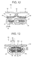
- a concealed slide fastener 80 disclosed in Patent Document 1 includes a right-and-left pair of fastener stringers 81 and a slider 82 capable of opening and closing the right and left fastener stringers 81, as illustrated in FIG. 13 .
- Each fastener stringer 81 of the right and left includes a woven fastener tape 83 and a continuously-shaped fastener element 84 which is sewn to the fastener tape 83.
- Each fastener tape 83 includes a tape body portion 83a, a tape bend portion 83b bent into a U-shape as extending from one side edge of the tape body portion 83a in the tape width direction, and an element mounting portion 83c to which a fastener element is sewn as further extending from the tape bend portion 83b.
- a hardened portion 83d hardened by being impregnated with synthetic resin liquid is disposed to the element mounting portion 83c and a part of the tape bend portion 83b at the element mounting portion 83c side.
- the fastener element 84 includes a coupling head 84a, upper and lower leg portions 84b, 84c extending from the coupling head 84a, and a connecting portion 84d which connects the mutually adjacent fastener elements 84. Further, a recess 84e to which the fastener tape 83 is inserted is formed at the upper face of the upper leg portion 84b which is contacted to the fastener tape 83.
- the fastener element 84 is sewn to the hardened element mounting portion 83c of the fastener tape 83 with a sewing thread 85 in a state that the hardened portion 83d of the fastener tape 83 is fitted to the recess 84e which is formed at the fastener element 84.
- a concealed slide fastener in which hardening is performed by fixing a synthetic-resin-made film body to one face (i.e., a tape outer face) of a partial area of a fastener tape instead of hardening a partial area by impregnating with synthetic resin liquid is disclosed as a modified example of the concealed slide fastener. It is possible to harden a partial area of a fastener tape also by fixing a synthetic-resin-made film body to the partial area of the fastener tape as described above. Thus, a closely-contacted state between the tape bend portions of the right and left fastener tapes can be stably maintained also by fixing the film body in a state that the right and left fastener elements are coupled. In this manner, the fastener elements can be stably concealed.
- the element mounting portion 83c and a part of the tape bend portion 83b of the fastener tape 83 are impregnated with synthetic resin liquid and the tape area impregnated with the synthetic resin liquid is hardened, as described above. Further, in Patent Document 1, the fastener element 84 is sewn to the hardened element mounting portion 83c with the sewing thread 85.
- the fastener element is sewn to the element mounting portion to which the film body is fixed after the film body is fixed to the element mounting portion and the like of the fastener tape.
- a sewing needle i.e., a sewing-machine needle
- thickness of the synthetic-resin-made film body is required to be set thick to some extent to harden the element mounting portion and the like.
- the thickness of the film body to be fixed to the element mounting portion is set to be excessively thick, piercing of a sewing needle to the element mounting portion and the film body becomes difficult when the fastener element is sewn to the element mounting portion. Accordingly, there has been a problem that sewing of the fastener element cannot be smoothly performed.
- irregularity and burr are to be generated at a top face or a back face of the film body when a sewing needle pierces the synthetic-resin-made film body.
- irregularity and burr occur at the film body as described above, there has been a problem that appearance quality of the concealed slide fastener is lowered owing to occurrence of positional shifting of the fastener element and exposure of the irregularity and burr, for example.
- the invention provides a fastener stringer for a concealed slide fastener which is capable of having superior concealing characteristics enabling to stably conceal a fastener element even if lateral tension force is applied to right and left fastener tapes in a state that the fastener elements are coupled without worsening hand feeling and lowering appearance quality of the fastener tapes, and further, capable of smoothly performing sewing of the fastener element when the fastener element is sewn to the element mounting portion.
- a fastener stringer for a concealed slide fastener includes a right-and-left pair of woven fastener tapes which respectively include a tape body portion, a tape bend portion bent into a U-shape as extending from one side edge of the tape body portion in the tape width direction, and an element mounting portion to which the fastener element is sewn as further extending from the tape bend portion; and a continuously-shaped fastener element which is sewn to the right and left fastener tape with a sewing thread.
- the fastener stringer is characterized mainly in that the fastener tapes respectively include a hollow weave portion formed by continuous hollow weaving as accommodating a film body; the hollow weave portion includes a needle thread piercing area where a needle thread of the sewing thread at the tape bend portion side pierces; and the film body accommodated in the hollow weave portion is sewn together with the fastener element with the needle thread in a state that one side edge of the film body is located to the tape bend portion side from the needle thread.
- the hollow weave portion is formed up to the vicinity of a position where the tape bend portions of the right-and-left pair of fastener tapes are closely contacted. Further, it is preferable that the entire element mounting portion is formed by the hollow weaving.
- warp yarns are disposed to a tape side edge side of the element mounting portion from the other end edge of the film body as being aligned in the tape top-back direction.
- the warp yarns of the hollow weaving disposed at a tape outer face side and a tape inner face side of the film body have 1/3 and 3/1 structures and the warp yarns for positioning have a 2/2 structure.
- the film bodies are accommodated in the hollow weaving as being overlaid.
- the film body has thickness between 0.05 mm and 0.30 mm inclusive.
- the film body is made of at least one kind of materials being selected from groups of polyester resin, polypropylene resin, nylon resin and polycarbonate resin.
- the film body is made of polyester resin.
- the film body has a winding shape in a wavelike fashion along the tape longitudinal direction.
- warp yarns and weft yarns forming the fastener tape adopt threads between 167 dtex and 330 dtex inclusive and 4.5 dtex/f and 10.0 dtex/f inclusive.
- the fastener element is sewn to the fastener tape in double-chain stitching with the sewing thread and the needle thread of the sewing thread adopts a thread between 840 dtex and 990 dtex inclusive and a looper thread adopts a thread between 234 dtex and 705 dtex inclusive.
- the fastener tape includes the tape body portion, the tape bend portion which is bent into a U-shape , and the element mounting portion to which the fastener element is sewn.
- the fastener tape includes the hollow weave portion formed by continuous hollow weaving as accommodating the film body, and then, the hollow weave portion includes the needle thread piercing area where the needle thread of the sewing thread located at the tape bend portion side pierces.
- the film body accommodated in the hollow weave portion is sewn with the needle thread of the sewing thread in a state that one side edge of the film body is located to the tape bend portion side from the needle thread.
- the fastener stringer of the invention having the above structure, since the film body is accommodated in the hollow weave portion formed by hollow weaving, stiffness of the hollow weave portion can be easily improved without impairing appearance of the fastener stringer.
- the film body is sewn with the needle thread of the sewing thread in a state that one side edge of the film body is located to the tape bend portion side from the needle thread, the film body is to be accommodated at least at the end edge portion of the tape bend portion at the element mounting portion side in an immobile state. Accordingly, stiffness of the end edge portion can be reliably improved.
- the fastener element is sewn with the sewing thread to the element mounting portion which accommodates the film body, it is possible to have further effects of obtaining superior hand feeling at the fastener tape and superior flexibility of the fastener tape, for example, compared to a case that a fastener tape is impregnated with synthetic resin as disclosed in Patent Document 1, a case that a film body is fixed to one face of a fastener tape as an modified example of Patent Document 1, or a case that a fastener element is fixed to an element mounting portion by welding and the like.
- the hollow weave portion accommodating the film body is formed up to the vicinity of a position where the tape bend portions of the right and left fastener tapes are closely contacted. Accordingly, it is possible to improve stiffness of the hollow weave portion in the tape width direction from the element mounting portion to the vicinity of the position where the tape bend portions are closely contacted. With the above structure, it is possible to prevent the right and left tape bend portions more effectively from being moved in a separating direction even if lateral tension force is applied to the fastener tapes when the right and left fastener elements are in a coupled state.
- the entire element mounting portion is formed by the hollow weaving.
- warp yarns are disposed to the tape side edge side of the element mounting portion from the other edge of the film body as being aligned in the tape top-back direction. According to such warp yarn arrangement, the film body accommodated in the hollow weaving can be sewn to a predetermined position more reliably. In addition, it is possible to present occurrence of thread breakage of the warp yarns by suppressing direct contact of the warp yarns with an end part of the film body.
- the hollow weaving is formed such that the warp yarns disposed at the tape outer face side and the tape inner face side of the film body have 1/3 and 3/1 structures and the warp yarns for positioning have a 2/2 structure.
- the hollow weaving capable of stably holding the film body at the inside thereof can be reliably formed.
- the fastener stringer of the invention it is possible that at least two of the film bodies are accommodated in the hollow weaving as being overlaid.
- Various prototypes prepared by the inventors revealed that a needle can easily pierce a film body when sewing the film body to an element mounting portion of a fastener tape in a case that two film bodies having half thickness of a single film body are accommodated in the hollow weaving compared to a case that the single film body having large thickness is accommodated in the hollow weaving, for example.
- the needle passes through one film body, and then, passes through the other film body after the needle top exits from the one film body.
- the needle pierces one film body having thickness of the two overlaid film bodies, the needle top cannot exit from the film body until the needle completes to pierce the single film body.
- needle piercing is superior with two film bodies even if the thickness is the same.
- the film body has thickness between 0.05 mm and 0.30 mm inclusive. Stiffness of the hollow weave portion of the fastener tape accommodating the film bodies can be reliably improved by setting each thickness of the film bodies to be 0.05 mm or more.
- the fastener element can be located at a deeper position from a tape exposure face of the fastener stringer. Accordingly, even in a case that small clearance appears between the tape bend portions of the right and left fastener tape, for example, it is possible to make the fastener element less viewable from the tape exposure face side.
- the needle can pierce the film bodies more easily when sewing the film bodies to the element mounting portion together with the fastener element by setting each thickness of the film bodies to be 0.30 mm or less.
- the film body is made of at least one kind of materials being selected from groups of polyester resin, polypropylene resin, nylon resin and polycarbonate resin. Owing to that the film body is made of the above synthetic resin, in particular, of polyester resin, stiffness of the hollow weave portion can be stably improved and sewing of the fastener element can be smoothly performed.
- the film body has a winding shape in a wavelike fashion along the tape longitudinal direction. Owing to utilizing the film body having such a shape, stiffness of the abovementioned hollow weave portion in the tape width direction can be effectively improved and flexibility of the fastener tape in the tape longitudinal direction can be easily ensured.
- warp yarns and weft yarns forming the fastener tape adopt threads between 167 dtex and 330 dtex inclusive and 4.5 dtex/f and 10.0 dtex/f inclusive.
- stiffness of the entire fastener tape can be improved and concealing characteristics of the fastener stringer can be further improved.
- the seat cover is made of relatively thick cloth. Therefore, when the tape body portion of the fastener tape is softly formed, there is a fear that problems such as sewing shrinkage occur due to occurrence of wave-shaped shrinkage at the fastener tape caused by strong tension force of the sewing thread against the fastener tape when the fastener tape is sewn to the seat cover. On the contrary, owing to that stiffness of the entire fastener tape is improved as described above, it is possible to prevent occurrence of problems such as sewing shrinkage even when the fastener tape is sewn to a thick product.
- the fastener element is sewn to the fastener tape in double-chain stitching with the sewing thread and the needle thread of the sewing thread adopts a thread between 840 dtex and 990 dtex inclusive and a looper thread adopts a thread between 234 dtex and 705 dtex inclusive.
- fastener element is sewn to the element mounting portion of the fastener tape by utilizing the sewing thread having the needle thread and the looper thread as described above, it is possible that the fastener element is sewn to the element mounting portion as being strongly tightened with the needle thread without causing thread breakage. Further, owing to that the looper thread appearing on a lower leg portion of the fastener element is set to be thinner than the needle thread, the looper thread can be unobtrusive and appearance of the fastener stringer can be improved.
- FIG. 1 is a perspective view illustrating an automobile seat for which a fastener stringer for a concealed slide fastener according to the present embodiment is used.
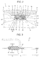
- FIG. 2 is a sectional view schematically illustrating a state that the fastener stringer is sewn to a surficial member of an automobile seat.
- FIGS. 3 to 5 are views schematically illustrating a weaving structure of a fastener tape.
- a fastener stringer 1 for a concealed slide fastener can structure a concealed slide fastener 2 as having a slider 3 slidably attached along fastener elements 20.
- the concealed slide fastener 2 structured by utilizing the fastener stringer 1 of the present embodiment is used as being attached to a back face side of a seat cover 6 of an automobile seat 5 as illustrated in FIG. 1 , for example.
- the concealed slide fastener 2 is attached to the seat cover 6 by sewing a tape body portion 11 of a fastener tape 10 of the fastener stringer 1 to a surficial member 6a of the seat cover 6 with a sewing thread 7. Description on the tape body portion 11 will be performed later. Further, the concealed slide fastener 2 is arranged between a cushion body 5a of the automobile seat 5 and the surficial member or the seat cover 6.
- the fastener stringer 1 of the present embodiment to be adopted to the seat cover 6 for automobiles and the like includes a right-and-left pair of woven fastener tapes 10, and coil-shaped fastener elements 20 sewn respectively to the right and left fastener tapers.
- the right and left fastener tapes 10 respectively include the tape body portion 11 to be sewn to the surficial member 6a of the seat cover 6, a tape bend portion 12 which is bent into a U-shape as extending from one side edge of the tape body portion 11 in the tape width direction, and a flat-shaped element mounting portion 13 further extending from the tape bend portions 12.
- the fastener tape 10 is woven to have a weaving structure as illustrated in FIGS. 3 to 5 .
- the weaving structure of the fastener tape 10 will be specifically described.
- black sections denote warp yarns routed above a weft yarn.
- the tape body portion 11 of the fastener tape 10 is woven to single weave with a plurality of warp yarns 31 and weft yarns 32 in which two single yarns are coupled as being paralleled. Then, the weaving structure of the tape body portion 11 is a 2/2 structure in which each warp yarn 31 is routed alternately to the upper side (i.e., the tape inner face side) of two sets of weft yarns 32 and to the lower side (i.e., the tape outer face side) of two sets of weft yarns 32.
- polyester fibers between 167 any 330 dtex inclusive and 4.5 dtex/f and 10.0 dtex/f inclusive, and preferably between 200 dtex and 300 dtex inclusive and 6.0 dtex/f and 8.0 dtex/f inclusive, are utilized for each single yarn arranged as the warp yarns 31 and the weft yarns 32.
- yarns having such thickness are called low-count yarns.
- Stiffness of the tape body portion 11 can be improved by structuring the warp yarns 31 and the weft yarns 32 with the abovementioned yards.
- the surficial member 6a of the automobile seat cover 6 is formed thick (see FIG. 2 )
- material of the warp yarns 31 and the weft yarns 32 is not specifically limited. It is possible to arbitrarily select and utilize synthetic fibers, natural fibers and the like other than polyester fibers for the warp yarns 31 and the weft yarns 32.
- the tape bend portion 12 of the fastener tape 10 is woven with a plurality of the warp yarns 31 and the weft yarns 32.
- the tape bend portion 12 includes a single weave portion 11a formed of the same weaving structure as the tape body portion 11 and a hollow weave portion 14 formed by hollow weaving.
- the single weave portion 11a of the tape bend portion 12 having the same weaving structure as the tape body portion 11 is formed continuously from the tape body portion 11.
- the hollow weave portion 14 of the tape bend portion 12 is arranged at the element mounting portion 13 side from the vicinity of a contacting section where the right and left tape bend portions 12 are closely contacted when the right end left fastener elements 20 are coupled as described later.
- the element mounting portion 13 of the fastener tape 10 includes the hollow weave portion 14 which is formed continuously from the tape bend portion 12. In the present embodiment, the hollow weave portion 14 is formed throughout the element mounting portion 13.
- the hollow weave portion 14 which is formed continuously at the tape bend portion 12 and the element mounting portion 13 accommodates two film bodies 15 in an overlaid state.
- the warp yarns 31 arranged at the hollow weave portion 14 includes a plurality of warp yarns 31a which are disposed to the tape inner side and the tape outer side of the film bodies 15 so as to nip the film bodies 15, and two warp yarns 31b which are disposed to an end edge at the element mounting 13 side.
- an end part of the hollow weave portion 14 at the tape bend portion 12 side is closed with a single weave portion 11a (i.e., connecting threads) formed at the tape bend portion 12.
- the plurality of warp yarns 31a disposed at the tape inner face side and the tape outer face side of the hollow weave portion 14 are woven as 1/3 and 3/1 structures in which the warp yarn 31a disposed to the tape inner face side is routed to the lower side (i.e., the film bodies 15 side) of a set of the weft yarns 32 and to the upper side (i.e., the tape inner face side) of three sets of the weft yarns 32 while the warp yarn 31a disposed to the tape outer face side is routed to the lower side (i.e., the tape outer face side) of three sets of weft yarns 32 and to the upper side (i.e., the film bodies 15 side) of a set of the weft yarns 32.
- the two warp yarns 31b disposed to the end edge of the hollow weave portion 14 at the element mounting portion 13 side are arranged in parallel to the tape longitudinal direction as being aligned in the tape top-back direction as positioning warp yarns which regulate an end edge position of the film bodies 15 at the element mounting portion 13 side.
- the weft yarns 31b are woven as the 2/2 structure in which each thereof is routed alternately to the upper side (i.e., the tape inner side) of two sets of the weft yarns 32 and to the lower side (i.e., the tape outer side) of two sets of weft yarns 32.
- yarns similar to the warp yarns 31 disposed to the tape body portion 11 are utilized for the warp yarns 31 disposed to the single weave portion 11a of the tape bend portion 12 and the warp yarns 31 disposed to hollow weave portion 14 of the tape bend portion 12 and the element mounting portion 13.
- material of the warp yarns 31 disposed to the tape bend portion 12 and the element mounting portion 13 is not specifically limited.
- the hollow weave portion 14 formed at the tape bend portion 12 and the element mounting portion 13 accommodates the two film bodies 15 as being overlaid.
- the film bodies 15 are formed of polyester resin which is capable of being plastically deformed at normal temperature. Thickness of the respective film bodies 15 is set between 0.05 mm and 0.30 mm inclusive, and preferably between 0.15 mm and 0.20 mm inclusive. Stiffness of the hollow weave portion 14 accommodating the film bodies 15 can be reliably improved by setting each thickness of the film bodies 15 to be 0.05 mm or more, in particular, to be 0.15 mm or more.
- the fastener element 20 when the fastener element 20 is sewn to the element mounting portion 13 with the sewing thread 35, sewing of the fastener element 20 is performed while a sewing needle 36 pierces the fastener tape 10 and the film bodies 15.
- the sewing needle 36 can easily pierce the film bodies 15 by setting each thickness of the film bodies 15 to be 0.30 mm or less, in particular, to be 0.20 mm or less. Accordingly, sewing of the fastener element 20 can be smoothly performed.
- the hollow weave portion 14 accommodates the two film bodies 15 made of polyester resin having thickness of 0.19 mm.
- the two film bodies 15 are accommodated in the hollow weave portion 14 of the fastener tape 10 in a straight state, as illustrated in FIG. 6 .
- a plurality of piercing holes 15a through which the sewing thread 35 (i.e., a needle thread 35a) passes are formed at the film bodies 15 as illustrated in FIG. 7 owing to piercing of the sewing needle 36 to the film bodies 15.
- the film bodies 15 are deformed into a winding shape (i.e., a meander shape) in a wavelike fashion in the tape longitudinal direction as receiving stress, friction force and the like from the sewing needle 36 when the sewing needle 36 pierces the film bodies 15 from a top face side to a back face side.
- a winding shape i.e., a meander shape
- the wavelike shape of the film bodies 15 in the tape longitudinal direction can effectively improve stiffness of the hollow weave portion 14 of the fastener tape 10 in the tape width direction. Meanwhile, it is possible to suppress decrease in flexibility in the tape longitudinal direction due to accommodating of the film bodies 15 in the hollow weave portion 14.
- the winding of the film bodies 15 may be formed by previously deforming the film bodies 15 into a meander shape in the longitudinal direction.
- the film bodies 15 accommodated in the hollow weave portion 14 may appropriately utilize material of synthetic resin such as polypropylene resin, nylon resin and polycarbonate resin, for example other than polyester resin. Further, in the present embodiment, the two film bodies 15 accommodated in the hollow weave portion 14 are made of the same material. However, in the invention, it is also possible that the two film bodies 15 made of mutually different material are accommodated in the hollow weave portion 14.
- the present embodiment exemplifies a structural example that the two film bodies 15 are accommodated in the hollow weave portion 14.
- the two film bodies 15 are accommodated in the hollow weave portion 14.
- the sewing needle 36 can easily pierce the element mounting portion 13 of the woven fastener tape 10 and sewing fastener element 20 can be stably performed even though the total thickness of the two film bodies 15 is larger than 0.3 mm.
- the total thickness of the plurality of film bodies 15 is 0.60 mm or less.
- each fastener element 20 includes a coupling head 21, upper and lower leg portions 22, 23 extending from the coupling head 21, and a connecting portion 24 which connects the mutually adjacent fastener elements 20.
- the core thread 27 passes between the upper and lower leg portions 22, 23.
- a recess 25 capable of accommodating the sewing thread 35 with which the fastener element 20 is sewn to the fastener tape 10 is formed at a lower face of the lower leg portion 23 of the fastener element 20.
- the fastener element 20 as described above is sewn to the element mounting portion 13 of the fastener tape 10 in double-chain stitching with the sewing thread 35 together with the two film bodies 15.
- the sewing thread 35 includes the needle thread 35a passing through the element mounting portion 13 of the fastener tape 10 and the film bodies 15, and a looper thread 35b routed at the lower leg portion 23 side of the fastener element 20 as being interlaced with the needle thread 35a between the fastener elements 20.
- the hollow weave portion 14 of the fastener tape 10 is formed to include at least the needle thread piercing area.
- the needle tread 35a of the sewing thread 35 adopts a thread between 840 dtex and 990 dtex inclusive.
- the looper thread 35b adopts a thread between 234 dtex and 705 dtex inclusive.
- the looper thread 35b exposed to the lower leg portion 23 side of the fastener element 20 can be unobtrusive to the extent possible. Accordingly, appearance of the fastener stringer 1 can be improved.
- the looper thread 35b of the sewing thread 35 is accommodated in the recess 25 of the fastener element 20 when the fastener element 20 is sewn. Accordingly, even if the slider 3 is slid along an element row of the fastener elements 20 with the structure of the concealed slide fastener 2 , the looper thread 35b can be prevented from being interfered with the slider 3. Therefore, it is possible to prevent occurrence of thread breakage at the looper thread 35b due to friction between the looper thread 35b and the slider 3.
- the fastener tape 10 having the weaving structure illustrated in FIGS. 3 to 5 is woven with weft-routing of the weft yarns 32 as reciprocating a carrier bar in an opening of the warp yarns 31 by utilizing a double-warp loom.
- the film bodies 15 are woven in the hollow weave portion 14 of the fastener tape 10 by supplying the overlaid film bodies 15 as one of the warp yarns. In this manner, it is possible to obtain the stripe-shaped fastener tape 10 accommodating the two film bodies 15 in the hollow weave portion 14 in a straight state as illustrated in FIG. 6 .
- the coil-shaped fastener element 20 is sewn to the element mounting portion 13 of the fastener tape 10 which is woven as described above.
- the fastener element 20 is sewn to the stripe-shaped fastener tape 10 which is not bent into a U-shape yet by utilizing the sewing thread 35 in a state that the core thread 27 is routed between the upper and lower leg portions 22, 23 of the fastener element 20.
- the fastener element 20 is sewn in double-chain stitching with the sewing thread 35 which includes the needle thread 35a and the looper thread 35b in a state that the coupling head 21 is oriented to the tape bend portion 12 side of the fastener tape 10 and the upper leg portion 22 is contacted to the fastener tape 10.
- the film bodies 15 accommodated in the hollow weave portion 14 of the fastener tape 10 are also sewn with the sewing thread 35 to the fastener tape 10 together with the fastener element 20.
- the fastener element 20 can be firmly sewn to a predetermined position
- the sewing needle 36 for performing sewing sews the fastener element 20 while piercing the fastener tape 10 and the two film bodies 15, the plurality of piercing holes 15a through which the needle thread or the sewing thread 35 passes are formed as being aligned in two lines and the film bodies 15 are deformed into a winding form in a wavelike fashion along the tape longitudinal direction, as illustrated in FIG. 7 .
- the coupling head 21 of the fastener element 20 is protruded outward from the tape bend portion 12 by bending the fastener tape 10 to which the fastener element 20 is sewn into a U-shape at the tape bend portion 12.
- the location of the film bodies 15 in the hollow weave portion 14 is restricted by the two warp yarns disposes at the end part of the hollow weave portion 14 at the tape bend portion 12 side. Further, the location of the film bodies 15 is fixed by the sewing thread 35. Accordingly, the film bodies 15 accommodated in the hollow weave portion 14 is not moved even when the fastener tape 10 is bent into a U-shape as described above. Thus, the location thereof can be stably maintained.
- the fastener stringer 1 is manufactures.
- the fastener stringer 1 obtained as described above, the two film bodies 15 are fixed with the sewing thread 35 in a state of being accommodated in the hollow weave portion 14.
- the fastener stringer 1 is configured to have the area of the fastener tape 10 having increased stiffness where the hollow weave portion 14 is formed without lowering appearance quality.
- the hollow weave portion 14 is formed at the tape bend portion 12 side from the needle thread 35a of the sewing thread 35 in the fastener stringer 1, stiffness of the tape section up to the vicinity of a position where the tape bend portions 12 are closely contacted is reliably improved when the right and left fastener elements 20 are in a coupled state. Further, in this case, since the fastener element 20 and the film bodies 15 are connected with the sewing thread 35 and relative positional deviation is prevented between the fastener element 20 and the film bodies 15, the closely-contacted state between the right and left tape bend portions 12 can be stably maintained.
- the fastener stringer 1 of the present embodiment remarkably improved concealing characteristics to conceal the fastener elements 20.
- FIG. 8 even when lateral tension force to open the fastener tapes 10 in the lateral direction is applied in a state that the right and left fastener elements 20 are coupled, clearance-forming is suppressed between the right and left fastener tapes in Accordingly, compared to a general concealed slide fastener in the related art, the fastener elements 20 can be further prevented from being viewed through the clearance from an exposure face side of the fastener stringer 1.
- the distance from the exposure face of the fastener stringer 1 to the fastener element 20 is maintained longer than that of the conventional fastener stringer 1. According to the above lengthened distance from the exposure face of the fastener stringer 1 to the fastener element 20, visibility of the fastener element 20 from the exposure face side of the fastener stringer 1 can be reduced even if small clearance is formed between the right and left fastener tapes 10 when strong lateral tension force is applied to the fastener stringer 1, for example.
- the concealed slide fastener 2 using the fastener stringer 1 of the present embodiment is used for the seat cover 6 for automobiles as illustrated in FIG. 1 , the right and left fastener elements 20 in a coupled state can be effectively prevented from being viewed from the cover outside.
- the above embodiment describes a preferable example of the fastener stringer 1 within the scope of the invention.
- the invention can be variously modified under conditions of having substantially the same structure and similar operational effects .
- length of the hollow weave portion 14 and the film body 15 of the fastener tape 10 can be arbitrarily modified as long as one side edge of the hollow weave portion 14 accommodating the film body 15 (in other words, one side edge of the film body 15) is arranged at the tape bend portion 12 side from the needle thread 35a of the sewing thread 35.
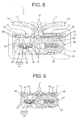
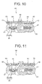
- a fastener stringer 49 in which a hollow weave portion 44 accommodating a film body 45 of a fastener tape 40 is formed longer to a tape bend portion 42 side than that in the fastener stringer 1 (see FIG. 2 ) of the above embodiment.
- thermal setting is performed on the fastener stringer 49 in a state that the side edge section of the film body 45 at the tape bend portion 42 side is bent together with a fastener tape 40. Since the hollow weave portion 44 accommodating the film body 45 can be formed longer to the tape bend portion 42 side as described above, clearance occurrence can be further prevented between tape bend portions 42 of the right and left fastener tapes 40 when the right and left fastener elements 20 are coupled. Accordingly, concealing characteristics of the fastener stringer 49 can be further improved.
- shrinkage occurs at the fastener tape 40 and the film body 45.
- a film body 55 is accommodate in a hollow weave portion 54 of a fastener tape 50 as being deformed into a winding shape in the top-back direction in a wavelike manner along the tape width direction owing to the shrinkage.
- stiffness of the hollow weave portion 54 of the fastener tape 50 is increased by the film body 55 to provide superior concealing characteristics.
- a fastener stringer 69 can be structured such that the needle thread 35a of the sewing thread 35 routed at a tape bend portion 62 side is located as being closer to the connecting portion 24 side of the fastener element 20 compared to the fastener stinger 1 (see FIG. 2 ) according to the above embodiment.
- a hollow weave portion 64 accommodating the film body 65 is formed longer to the tape bend portion 42 side compared to the fastener stringer 1 of the above embodiment.
- each film body 65 accommodated in the right and left fastener tapes 60 is bent to be apart rising from the fastener element 20 toward a close contact section of the tape bend portion 62 when the right and left fastener elements 20 are coupled.
- the right and left film bodies 65 are in a mutually-pushed state, the right and left tape bend portions 42 can be closely contacted to each other more stably.
Landscapes
- Engineering & Computer Science (AREA)
- Textile Engineering (AREA)
- Slide Fasteners (AREA)
- Purses, Travelling Bags, Baskets, Or Suitcases (AREA)
- Sewing Machines And Sewing (AREA)
Applications Claiming Priority (1)
| Application Number | Priority Date | Filing Date | Title |
|---|---|---|---|
| PCT/JP2009/065915 WO2011030442A1 (ja) | 2009-09-11 | 2009-09-11 | 隠しスライドファスナー用ファスナーストリンガー |
Publications (3)
| Publication Number | Publication Date |
|---|---|
| EP2476333A1 true EP2476333A1 (de) | 2012-07-18 |
| EP2476333A4 EP2476333A4 (de) | 2013-11-13 |
| EP2476333B1 EP2476333B1 (de) | 2015-07-01 |
Family
ID=43732127
Family Applications (1)
| Application Number | Title | Priority Date | Filing Date |
|---|---|---|---|
| EP09849221.8A Active EP2476333B1 (de) | 2009-09-11 | 2009-09-11 | Verschlussleiste für verborgenen reissverschluss |
Country Status (8)
| Country | Link |
|---|---|
| US (1) | US9089187B2 (de) |
| EP (1) | EP2476333B1 (de) |
| JP (1) | JP5430663B2 (de) |
| KR (1) | KR101274938B1 (de) |
| CN (1) | CN102481040B (de) |
| ES (1) | ES2547709T3 (de) |
| TW (1) | TWI389651B (de) |
| WO (1) | WO2011030442A1 (de) |
Cited By (1)
| Publication number | Priority date | Publication date | Assignee | Title |
|---|---|---|---|---|
| EP4151115A4 (de) * | 2020-09-18 | 2023-10-25 | Kee (Hubei) Zippers Manufacturing Limited | Verbesserter verschlussstringer, reissverschluss, hautprodukt und herstellungsverfahren dafür |
Families Citing this family (21)
| Publication number | Priority date | Publication date | Assignee | Title |
|---|---|---|---|---|
| US9173458B2 (en) * | 2013-06-07 | 2015-11-03 | Lien-Chou Wang | Waterproof, anti-split, high transverse tensile strength double-layer zipper and its fabrication method |
| US8894111B2 (en) | 2013-08-16 | 2014-11-25 | Ykk Corporation Of America | Slide fastener closing tool and method |
| TWI576063B (zh) * | 2013-12-16 | 2017-04-01 | Ykk Corp | Chains without zipper chains and items with zippers |
| CN103750603A (zh) * | 2013-12-23 | 2014-04-30 | 天津应大股份有限公司 | 一种蕾丝面料隐形拉链防护结构 |
| WO2017094155A1 (ja) * | 2015-12-02 | 2017-06-08 | Ykk株式会社 | カバー取付構造体、及びカバー取付構造体のカバー取付方法 |
| CN105768393A (zh) * | 2016-03-13 | 2016-07-20 | 郑运婷 | 双层保护拉链 |
| US11071357B2 (en) * | 2017-02-02 | 2021-07-27 | Ykk Corporation | Slide fastener and method for manufacturing same |
| CN107485131A (zh) * | 2017-09-30 | 2017-12-19 | 开易(广东)服装配件有限公司 | 拉链用布带及其组成的拉链 |
| JP6980557B2 (ja) * | 2018-02-19 | 2021-12-15 | Ykk株式会社 | ファスナーストリンガー、スライドファスナーおよびファスナーストリンガー取付構造 |
| US11363860B2 (en) | 2019-11-23 | 2022-06-21 | Talon Technologies, Inc. | Waterproof curved zippers |
| JP2023503233A (ja) | 2019-11-23 | 2023-01-27 | タロン テクノロジーズ、インコーポレイティッド | 湾曲ジッパー |
| US11877628B2 (en) | 2019-12-12 | 2024-01-23 | Ykk Corporation | Watertight fastener and method for manufacturing same |
| CN212729036U (zh) * | 2020-09-18 | 2021-03-19 | 开易(广东)服装配件有限公司 | 第一种改进的链带、拉链及所应用的蒙皮用具 |
| CN112075728A (zh) * | 2020-09-18 | 2020-12-15 | 开易(广东)服装配件有限公司 | 第二种改进的链带、拉链、蒙皮用具及其形成方法 |
| CN115956741B (zh) * | 2021-10-12 | 2025-11-28 | 吉田拉链(深圳)有限公司 | 隐形拉链 |
| CN118302082A (zh) * | 2021-11-10 | 2024-07-05 | Ykk株式会社 | 拉链链条 |
| WO2023243081A1 (ja) * | 2022-06-17 | 2023-12-21 | Ykk株式会社 | スライドファスナー |
| CN117617643A (zh) * | 2022-08-15 | 2024-03-01 | Ykk株式会社 | 隐形拉链组件 |
| EP4437901B1 (de) * | 2023-03-23 | 2026-04-01 | Opti Group GmbH | Reissverschluss |
| JP2025124267A (ja) | 2024-02-14 | 2025-08-26 | Ykk株式会社 | ファスナーストリンガー |
| JP2025124268A (ja) | 2024-02-14 | 2025-08-26 | Ykk株式会社 | 隠しスライドファスナー |
Family Cites Families (32)
| Publication number | Priority date | Publication date | Assignee | Title |
|---|---|---|---|---|
| US3343234A (en) | 1967-09-26 | Continuous filament slide fastener | ||
| FR1227606A (fr) * | 1958-06-10 | 1960-08-22 | Perfectionnements apportés aux fermetures à glissière | |
| DE1610378A1 (de) * | 1967-01-10 | 1971-01-07 | Opti Holding Ag | Reissverschluss |
| JPS4944246B1 (de) | 1967-04-15 | 1974-11-27 | ||
| FR1536852A (fr) | 1967-09-15 | 1968-08-16 | Ytong Internat A B | Procédé pour la fabrication de briques de sable et de chaux |
| DE1908069A1 (de) | 1969-02-18 | 1970-11-05 | Sohr Hans Ulrich | Verfahren zur Herstellung eines verdeckten Reissverschlusses |
| JPS514826Y1 (de) | 1970-01-21 | 1976-02-10 | ||
| NO141225L (de) * | 1974-03-25 | |||
| JPS514826U (de) | 1974-06-28 | 1976-01-14 | ||
| KR790001296Y1 (ko) * | 1974-12-18 | 1979-08-13 | 요시다 다다오 | 경편조(經編組) 스트링거 테이프를 가진 은폐형 슬라이드 파스너 |
| US4100656A (en) * | 1975-01-09 | 1978-07-18 | Textron Inc. | Slide fastener stringer and method of manufacture |
| DE2519829C3 (de) * | 1975-05-03 | 1979-05-31 | Opti-Patent-, Forschungs- Und Fabrikations-Ag, Glarus (Schweiz) | Reißverschluß aus Tragbändern und aufgewebten Verschlußgliederreihen |
| JPS5740804Y2 (de) * | 1977-05-18 | 1982-09-08 | ||
| AU545571B2 (en) * | 1983-05-11 | 1985-07-18 | Yoshida Kogyo K.K. | Slide fastener |
| JPH0734413B2 (ja) | 1986-07-29 | 1995-04-12 | ティーディーケイ株式会社 | 半導体磁器コンデンサ及びその製造方法 |
| JPH0434727Y2 (de) * | 1986-08-23 | 1992-08-18 | ||
| JP2755266B2 (ja) | 1989-09-14 | 1998-05-20 | 富士通株式会社 | シェルフに対してプリント基板を固定するための機構 |
| JPH057999Y2 (de) * | 1990-02-01 | 1993-03-01 | ||
| JPH0410711U (de) * | 1990-05-18 | 1992-01-29 | ||
| US5386616A (en) * | 1993-04-08 | 1995-02-07 | W. L. Gore & Associates, Inc. | Water resistant closure and method for applying same |
| JP3414110B2 (ja) * | 1996-02-29 | 2003-06-09 | ワイケイケイ株式会社 | 隠し織込みスライドファスナー |
| JP3580725B2 (ja) * | 1999-04-30 | 2004-10-27 | Ykk株式会社 | 防水性を有するスライドファスナーの製造方法 |
| JP3763743B2 (ja) * | 2001-01-31 | 2006-04-05 | Ykk株式会社 | スライドファスナーの製造方法 |
| JP2004016688A (ja) * | 2002-06-20 | 2004-01-22 | Ykk Corp | スライドファスナー |
| CN100551291C (zh) * | 2003-06-02 | 2009-10-21 | Ykk株式会社 | 针织、机织的隐形拉链 |
| JP4244024B2 (ja) * | 2004-07-05 | 2009-03-25 | Ykk株式会社 | 隠しスライドファスナー用スライダーと隠しスライドファスナー |
| JP4762113B2 (ja) | 2006-11-09 | 2011-08-31 | Ykk株式会社 | 隠しスライドファスナー用ファスナーストリンガー |
| JP2008303474A (ja) | 2007-06-05 | 2008-12-18 | Descente Ltd | スライドファスナーの玉縁構造 |
| FR2932343B1 (fr) | 2008-06-10 | 2012-11-30 | Alcatel Lucent | Procede de communication sur un reseau au moyen d'un lien |
| US8397353B2 (en) * | 2008-11-26 | 2013-03-19 | Chao-Mu Chou | Continuous-coil type waterproof slide fastener and the structure impervious to fluid thereof |
| GB0912179D0 (en) * | 2009-07-13 | 2009-08-26 | Ykk Europ Ltd | Watertight zip fastener |
| CN102481038B (zh) * | 2009-09-04 | 2015-06-03 | Ykk株式会社 | 隐形拉链用拉链条 |
-
2009
- 2009-09-11 JP JP2011530696A patent/JP5430663B2/ja active Active
- 2009-09-11 CN CN200980161353.7A patent/CN102481040B/zh active Active
- 2009-09-11 US US13/394,830 patent/US9089187B2/en active Active
- 2009-09-11 KR KR1020127003626A patent/KR101274938B1/ko active Active
- 2009-09-11 EP EP09849221.8A patent/EP2476333B1/de active Active
- 2009-09-11 ES ES09849221.8T patent/ES2547709T3/es active Active
- 2009-09-11 WO PCT/JP2009/065915 patent/WO2011030442A1/ja not_active Ceased
-
2010
- 2010-03-04 TW TW099106322A patent/TWI389651B/zh not_active IP Right Cessation
Cited By (2)
| Publication number | Priority date | Publication date | Assignee | Title |
|---|---|---|---|---|
| EP4151115A4 (de) * | 2020-09-18 | 2023-10-25 | Kee (Hubei) Zippers Manufacturing Limited | Verbesserter verschlussstringer, reissverschluss, hautprodukt und herstellungsverfahren dafür |
| US12022918B2 (en) | 2020-09-18 | 2024-07-02 | Kee (Hubei) Zippers Manufacturing Limited | Fastener tape, slide fastener, skin product, and method of forming fastener tape |
Also Published As
| Publication number | Publication date |
|---|---|
| TWI389651B (zh) | 2013-03-21 |
| JPWO2011030442A1 (ja) | 2013-02-04 |
| TW201108961A (en) | 2011-03-16 |
| ES2547709T3 (es) | 2015-10-08 |
| CN102481040A (zh) | 2012-05-30 |
| JP5430663B2 (ja) | 2014-03-05 |
| EP2476333A4 (de) | 2013-11-13 |
| US20120167355A1 (en) | 2012-07-05 |
| CN102481040B (zh) | 2014-10-29 |
| US9089187B2 (en) | 2015-07-28 |
| KR20120034230A (ko) | 2012-04-10 |
| KR101274938B1 (ko) | 2013-06-17 |
| EP2476333B1 (de) | 2015-07-01 |
| WO2011030442A1 (ja) | 2011-03-17 |
Similar Documents
| Publication | Publication Date | Title |
|---|---|---|
| EP2476333B1 (de) | Verschlussleiste für verborgenen reissverschluss | |
| US11206901B2 (en) | Slide fastener-attached product, element member and manufacturing method of slide fastener-attached product | |
| JP6091528B2 (ja) | ファスナーテープ無しストリンガーの被着物品及びスライドファスナー付き物品 | |
| WO2016016952A1 (ja) | ファスナーテープ無しストリンガー、ファスナーテープ無しスライドファスナー、及びスライドファスナー付き物品 | |
| CN202819883U (zh) | 拉链长链 | |
| US12336602B2 (en) | Fastener stringer and method for manufacturing fastener stringer | |
| JP2022030892A (ja) | 編込みファスナーストリンガー及びカバー部材 | |
| CN224038593U (zh) | 一种具备刚性的拉链条、隐形拉链及带拉链制品 | |
| KR20250125269A (ko) | 파스너 스트링거 | |
| JP2025124268A (ja) | 隠しスライドファスナー |
Legal Events
| Date | Code | Title | Description |
|---|---|---|---|
| PUAI | Public reference made under article 153(3) epc to a published international application that has entered the european phase |
Free format text: ORIGINAL CODE: 0009012 |
|
| 17P | Request for examination filed |
Effective date: 20120326 |
|
| AK | Designated contracting states |
Kind code of ref document: A1 Designated state(s): AT BE BG CH CY CZ DE DK EE ES FI FR GB GR HR HU IE IS IT LI LT LU LV MC MK MT NL NO PL PT RO SE SI SK SM TR |
|
| DAX | Request for extension of the european patent (deleted) | ||
| A4 | Supplementary search report drawn up and despatched |
Effective date: 20131011 |
|
| RIC1 | Information provided on ipc code assigned before grant |
Ipc: D03D 3/02 20060101ALI20131007BHEP Ipc: A44B 19/08 20060101ALI20131007BHEP Ipc: A44B 19/40 20060101AFI20131007BHEP Ipc: A44B 19/34 20060101ALI20131007BHEP |
|
| GRAP | Despatch of communication of intention to grant a patent |
Free format text: ORIGINAL CODE: EPIDOSNIGR1 |
|
| INTG | Intention to grant announced |
Effective date: 20150306 |
|
| GRAS | Grant fee paid |
Free format text: ORIGINAL CODE: EPIDOSNIGR3 |
|
| GRAA | (expected) grant |
Free format text: ORIGINAL CODE: 0009210 |
|
| AK | Designated contracting states |
Kind code of ref document: B1 Designated state(s): AT BE BG CH CY CZ DE DK EE ES FI FR GB GR HR HU IE IS IT LI LT LU LV MC MK MT NL NO PL PT RO SE SI SK SM TR |
|
| REG | Reference to a national code |
Ref country code: GB Ref legal event code: FG4D |
|
| REG | Reference to a national code |
Ref country code: AT Ref legal event code: REF Ref document number: 733410 Country of ref document: AT Kind code of ref document: T Effective date: 20150715 Ref country code: CH Ref legal event code: EP |
|
| REG | Reference to a national code |
Ref country code: IE Ref legal event code: FG4D |
|
| REG | Reference to a national code |
Ref country code: DE Ref legal event code: R096 Ref document number: 602009032010 Country of ref document: DE |
|
| REG | Reference to a national code |
Ref country code: ES Ref legal event code: FG2A Ref document number: 2547709 Country of ref document: ES Kind code of ref document: T3 Effective date: 20151008 |
|
| REG | Reference to a national code |
Ref country code: AT Ref legal event code: MK05 Ref document number: 733410 Country of ref document: AT Kind code of ref document: T Effective date: 20150701 |
|
| REG | Reference to a national code |
Ref country code: NL Ref legal event code: MP Effective date: 20150701 |
|
| REG | Reference to a national code |
Ref country code: LT Ref legal event code: MG4D |
|
| PG25 | Lapsed in a contracting state [announced via postgrant information from national office to epo] |
Ref country code: LT Free format text: LAPSE BECAUSE OF FAILURE TO SUBMIT A TRANSLATION OF THE DESCRIPTION OR TO PAY THE FEE WITHIN THE PRESCRIBED TIME-LIMIT Effective date: 20150701 Ref country code: GR Free format text: LAPSE BECAUSE OF FAILURE TO SUBMIT A TRANSLATION OF THE DESCRIPTION OR TO PAY THE FEE WITHIN THE PRESCRIBED TIME-LIMIT Effective date: 20151002 Ref country code: LV Free format text: LAPSE BECAUSE OF FAILURE TO SUBMIT A TRANSLATION OF THE DESCRIPTION OR TO PAY THE FEE WITHIN THE PRESCRIBED TIME-LIMIT Effective date: 20150701 Ref country code: NO Free format text: LAPSE BECAUSE OF FAILURE TO SUBMIT A TRANSLATION OF THE DESCRIPTION OR TO PAY THE FEE WITHIN THE PRESCRIBED TIME-LIMIT Effective date: 20151001 Ref country code: FI Free format text: LAPSE BECAUSE OF FAILURE TO SUBMIT A TRANSLATION OF THE DESCRIPTION OR TO PAY THE FEE WITHIN THE PRESCRIBED TIME-LIMIT Effective date: 20150701 |
|
| PG25 | Lapsed in a contracting state [announced via postgrant information from national office to epo] |
Ref country code: IS Free format text: LAPSE BECAUSE OF FAILURE TO SUBMIT A TRANSLATION OF THE DESCRIPTION OR TO PAY THE FEE WITHIN THE PRESCRIBED TIME-LIMIT Effective date: 20151101 Ref country code: PL Free format text: LAPSE BECAUSE OF FAILURE TO SUBMIT A TRANSLATION OF THE DESCRIPTION OR TO PAY THE FEE WITHIN THE PRESCRIBED TIME-LIMIT Effective date: 20150701 Ref country code: HR Free format text: LAPSE BECAUSE OF FAILURE TO SUBMIT A TRANSLATION OF THE DESCRIPTION OR TO PAY THE FEE WITHIN THE PRESCRIBED TIME-LIMIT Effective date: 20150701 Ref country code: SE Free format text: LAPSE BECAUSE OF FAILURE TO SUBMIT A TRANSLATION OF THE DESCRIPTION OR TO PAY THE FEE WITHIN THE PRESCRIBED TIME-LIMIT Effective date: 20150701 Ref country code: PT Free format text: LAPSE BECAUSE OF FAILURE TO SUBMIT A TRANSLATION OF THE DESCRIPTION OR TO PAY THE FEE WITHIN THE PRESCRIBED TIME-LIMIT Effective date: 20151102 Ref country code: AT Free format text: LAPSE BECAUSE OF FAILURE TO SUBMIT A TRANSLATION OF THE DESCRIPTION OR TO PAY THE FEE WITHIN THE PRESCRIBED TIME-LIMIT Effective date: 20150701 |
|
| REG | Reference to a national code |
Ref country code: DE Ref legal event code: R097 Ref document number: 602009032010 Country of ref document: DE |
|
| PG25 | Lapsed in a contracting state [announced via postgrant information from national office to epo] |
Ref country code: DK Free format text: LAPSE BECAUSE OF FAILURE TO SUBMIT A TRANSLATION OF THE DESCRIPTION OR TO PAY THE FEE WITHIN THE PRESCRIBED TIME-LIMIT Effective date: 20150701 Ref country code: CZ Free format text: LAPSE BECAUSE OF FAILURE TO SUBMIT A TRANSLATION OF THE DESCRIPTION OR TO PAY THE FEE WITHIN THE PRESCRIBED TIME-LIMIT Effective date: 20150701 Ref country code: MC Free format text: LAPSE BECAUSE OF FAILURE TO SUBMIT A TRANSLATION OF THE DESCRIPTION OR TO PAY THE FEE WITHIN THE PRESCRIBED TIME-LIMIT Effective date: 20150701 Ref country code: EE Free format text: LAPSE BECAUSE OF FAILURE TO SUBMIT A TRANSLATION OF THE DESCRIPTION OR TO PAY THE FEE WITHIN THE PRESCRIBED TIME-LIMIT Effective date: 20150701 Ref country code: SK Free format text: LAPSE BECAUSE OF FAILURE TO SUBMIT A TRANSLATION OF THE DESCRIPTION OR TO PAY THE FEE WITHIN THE PRESCRIBED TIME-LIMIT Effective date: 20150701 Ref country code: LU Free format text: LAPSE BECAUSE OF FAILURE TO SUBMIT A TRANSLATION OF THE DESCRIPTION OR TO PAY THE FEE WITHIN THE PRESCRIBED TIME-LIMIT Effective date: 20150911 |
|
| REG | Reference to a national code |
Ref country code: CH Ref legal event code: PL |
|
| PLBE | No opposition filed within time limit |
Free format text: ORIGINAL CODE: 0009261 |
|
| STAA | Information on the status of an ep patent application or granted ep patent |
Free format text: STATUS: NO OPPOSITION FILED WITHIN TIME LIMIT |
|
| PG25 | Lapsed in a contracting state [announced via postgrant information from national office to epo] |
Ref country code: RO Free format text: LAPSE BECAUSE OF FAILURE TO SUBMIT A TRANSLATION OF THE DESCRIPTION OR TO PAY THE FEE WITHIN THE PRESCRIBED TIME-LIMIT Effective date: 20150701 |
|
| 26N | No opposition filed |
Effective date: 20160404 |
|
| GBPC | Gb: european patent ceased through non-payment of renewal fee |
Effective date: 20151001 |
|
| REG | Reference to a national code |
Ref country code: IE Ref legal event code: MM4A |
|
| PG25 | Lapsed in a contracting state [announced via postgrant information from national office to epo] |
Ref country code: IE Free format text: LAPSE BECAUSE OF NON-PAYMENT OF DUE FEES Effective date: 20150911 Ref country code: CH Free format text: LAPSE BECAUSE OF NON-PAYMENT OF DUE FEES Effective date: 20150930 Ref country code: GB Free format text: LAPSE BECAUSE OF NON-PAYMENT OF DUE FEES Effective date: 20151001 Ref country code: LI Free format text: LAPSE BECAUSE OF NON-PAYMENT OF DUE FEES Effective date: 20150930 |
|
| REG | Reference to a national code |
Ref country code: FR Ref legal event code: PLFP Year of fee payment: 8 |
|
| PG25 | Lapsed in a contracting state [announced via postgrant information from national office to epo] |
Ref country code: SI Free format text: LAPSE BECAUSE OF FAILURE TO SUBMIT A TRANSLATION OF THE DESCRIPTION OR TO PAY THE FEE WITHIN THE PRESCRIBED TIME-LIMIT Effective date: 20150701 |
|
| PG25 | Lapsed in a contracting state [announced via postgrant information from national office to epo] |
Ref country code: BE Free format text: LAPSE BECAUSE OF FAILURE TO SUBMIT A TRANSLATION OF THE DESCRIPTION OR TO PAY THE FEE WITHIN THE PRESCRIBED TIME-LIMIT Effective date: 20150701 |
|
| PG25 | Lapsed in a contracting state [announced via postgrant information from national office to epo] |
Ref country code: MT Free format text: LAPSE BECAUSE OF FAILURE TO SUBMIT A TRANSLATION OF THE DESCRIPTION OR TO PAY THE FEE WITHIN THE PRESCRIBED TIME-LIMIT Effective date: 20150701 |
|
| PG25 | Lapsed in a contracting state [announced via postgrant information from national office to epo] |
Ref country code: SM Free format text: LAPSE BECAUSE OF FAILURE TO SUBMIT A TRANSLATION OF THE DESCRIPTION OR TO PAY THE FEE WITHIN THE PRESCRIBED TIME-LIMIT Effective date: 20150701 Ref country code: HU Free format text: LAPSE BECAUSE OF FAILURE TO SUBMIT A TRANSLATION OF THE DESCRIPTION OR TO PAY THE FEE WITHIN THE PRESCRIBED TIME-LIMIT; INVALID AB INITIO Effective date: 20090911 Ref country code: BG Free format text: LAPSE BECAUSE OF FAILURE TO SUBMIT A TRANSLATION OF THE DESCRIPTION OR TO PAY THE FEE WITHIN THE PRESCRIBED TIME-LIMIT Effective date: 20150701 |
|
| PG25 | Lapsed in a contracting state [announced via postgrant information from national office to epo] |
Ref country code: CY Free format text: LAPSE BECAUSE OF FAILURE TO SUBMIT A TRANSLATION OF THE DESCRIPTION OR TO PAY THE FEE WITHIN THE PRESCRIBED TIME-LIMIT Effective date: 20150701 Ref country code: NL Free format text: LAPSE BECAUSE OF FAILURE TO SUBMIT A TRANSLATION OF THE DESCRIPTION OR TO PAY THE FEE WITHIN THE PRESCRIBED TIME-LIMIT Effective date: 20150701 |
|
| REG | Reference to a national code |
Ref country code: FR Ref legal event code: PLFP Year of fee payment: 9 |
|
| PG25 | Lapsed in a contracting state [announced via postgrant information from national office to epo] |
Ref country code: TR Free format text: LAPSE BECAUSE OF FAILURE TO SUBMIT A TRANSLATION OF THE DESCRIPTION OR TO PAY THE FEE WITHIN THE PRESCRIBED TIME-LIMIT Effective date: 20150701 |
|
| PG25 | Lapsed in a contracting state [announced via postgrant information from national office to epo] |
Ref country code: MK Free format text: LAPSE BECAUSE OF FAILURE TO SUBMIT A TRANSLATION OF THE DESCRIPTION OR TO PAY THE FEE WITHIN THE PRESCRIBED TIME-LIMIT Effective date: 20150701 |
|
| REG | Reference to a national code |
Ref country code: FR Ref legal event code: PLFP Year of fee payment: 10 |
|
| PGFP | Annual fee paid to national office [announced via postgrant information from national office to epo] |
Ref country code: IT Payment date: 20190917 Year of fee payment: 11 Ref country code: FR Payment date: 20190815 Year of fee payment: 11 |
|
| PGFP | Annual fee paid to national office [announced via postgrant information from national office to epo] |
Ref country code: ES Payment date: 20191002 Year of fee payment: 11 |
|
| PG25 | Lapsed in a contracting state [announced via postgrant information from national office to epo] |
Ref country code: FR Free format text: LAPSE BECAUSE OF NON-PAYMENT OF DUE FEES Effective date: 20200930 |
|
| PG25 | Lapsed in a contracting state [announced via postgrant information from national office to epo] |
Ref country code: IT Free format text: LAPSE BECAUSE OF NON-PAYMENT OF DUE FEES Effective date: 20200911 |
|
| REG | Reference to a national code |
Ref country code: ES Ref legal event code: FD2A Effective date: 20220118 |
|
| PG25 | Lapsed in a contracting state [announced via postgrant information from national office to epo] |
Ref country code: ES Free format text: LAPSE BECAUSE OF NON-PAYMENT OF DUE FEES Effective date: 20200912 |
|
| P01 | Opt-out of the competence of the unified patent court (upc) registered |
Effective date: 20230428 |
|
| PGFP | Annual fee paid to national office [announced via postgrant information from national office to epo] |
Ref country code: DE Payment date: 20250730 Year of fee payment: 17 |