EP2476464A1 - Rucksackartige Brandbekämpfungsvorrichtung und Behälter dafür - Google Patents
Rucksackartige Brandbekämpfungsvorrichtung und Behälter dafür Download PDFInfo
- Publication number
- EP2476464A1 EP2476464A1 EP11000244A EP11000244A EP2476464A1 EP 2476464 A1 EP2476464 A1 EP 2476464A1 EP 11000244 A EP11000244 A EP 11000244A EP 11000244 A EP11000244 A EP 11000244A EP 2476464 A1 EP2476464 A1 EP 2476464A1
- Authority
- EP
- European Patent Office
- Prior art keywords
- medium
- container
- shell
- medium reservoir
- recess
- Prior art date
- Legal status (The legal status is an assumption and is not a legal conclusion. Google has not performed a legal analysis and makes no representation as to the accuracy of the status listed.)
- Granted
Links
Images




Classifications
-
- A—HUMAN NECESSITIES
- A62—LIFE-SAVING; FIRE-FIGHTING
- A62C—FIRE-FIGHTING
- A62C15/00—Extinguishers essentially of the knapsack type
-
- A—HUMAN NECESSITIES
- A62—LIFE-SAVING; FIRE-FIGHTING
- A62C—FIRE-FIGHTING
- A62C13/00—Portable extinguishers which are permanently pressurised or pressurised immediately before use
- A62C13/62—Portable extinguishers which are permanently pressurised or pressurised immediately before use with a single permanently pressurised container
-
- A—HUMAN NECESSITIES
- A62—LIFE-SAVING; FIRE-FIGHTING
- A62C—FIRE-FIGHTING
- A62C13/00—Portable extinguishers which are permanently pressurised or pressurised immediately before use
- A62C13/66—Portable extinguishers which are permanently pressurised or pressurised immediately before use with extinguishing material and pressure gas being stored in separate containers
Definitions
- the present disclosure generally relates to firefighting devices.
- a portable firefighting device of the backpack type that is to be strapped to the back of a firefighter is described.
- a container for such a firefighting device is described.
- firefighting devices with a strap system that permits to strap the medium tank to the back of the firefighter (simply called “user” hereinafter).
- Such firefighting devices are referred to as being of the backpack type and typically also comprise an outlet hose and a spreading device connected thereto.
- Backpack type firefighting devices operate with a non-pressurized or with a pressurized fire extinguishing medium in the medium tank.
- the fire extinguishing medium such as water is pumped from the tank into the outlet hose.
- the firefighting device is equipped with a (typically battery-operated) pump system.
- the fire extinguishing medium stored in the tank is pressurized.
- the pressurizing may occur either upon filling the fire extinguishing medium into the medium tank or by activating a pressure source during operation of the firefighting device.
- the pressure source can take the form of a gas tank from which pressurized gas is selectively transferred (e.g., via a pressure regulator) into the medium tank.
- a container for a backpack type firefighting device to be strapped on a back of a user comprising a medium reservoir having at least one medium tank of an essentially round cylindrical shape and adapted to store a pressurized fire extinguishing medium, and a shell portably housing the medium reservoir and adapted to be connected to a strap system.
- a center of gravity of the medium reservoir is closer to its region facing the strap system than to its lateral regions.
- the medium reservoir may have a suitably selected (e.g., non-circular) overall shape.
- an envelope of the medium reservoir (as seen in a plane perpendicular to a user's spine) may have a first extension in a direction generally towards the strap system and a second extension perpendicular to the first extension, wherein the second extension is generally larger than the first extension.
- the shell of the container may be formed of a rigid material and may be realized as a one-piece or multi-piece structure.
- the shell may be shaped in its region facing the user to at least partially conform to the back of the user.
- the shell may be concavely shaped (e.g., curved).
- the medium reservoir may comprise a single tank of a round cylindrical (e.g., oval) shape.
- the medium reservoir may comprise two or more individual medium tanks, wherein each individual medium tank has a round cylindrical (e.g., oval or circular) shape.
- the individual medium tanks may be configured to communicate with each other.
- the medium tanks may be connected or connectable (e.g., via a pipe or pipe system).
- the medium tanks may selectively be connectable via a valve or any other flow control element.
- the shell may fully or partly enclose the medium reservoir. Further, the shell may comprise at least one recess (e.g., an opening in the shell or a depression of the shell) adapted to accommodate fire extinguishing equipment such as a pressure source (e.g., a gas tank filled with a pressurizing gas or a compressor), an outlet hose, a protective face mask, a gas tank filled with breathable air or a spreading device.
- a pressure source e.g., a gas tank filled with a pressurizing gas or a compressor
- the recess may have an axial extension generally parallel to a longitudinal axis of the at least one medium tank.
- the at least one recess is arranged in the shell in a location between two adjacent medium tanks such that the recess extends into an envelope of the two adjacent medium tanks.
- the fire extinguishing equipment can be brought closer to the center of gravity of the medium reservoir (and thus also closer to the back of the user).
- the at least one recess may have a cross-section in accordance with a U or V.
- the at least one recess may alternatively be defined as an opening in the shell.
- the at least one recess may be arranged in any region of the shell.
- the at least one recess may be arranged on at least one lateral side of the shell.
- one or more recesses may be arranged in a region of the shell facing away from the strap system (i.e., from a user's perspective, on a backside of the container).
- the at least one recess may be adapted to (e.g., detachably) accommodate a gas tank filled with breathable air or a pressure source for pressurizing the fire extinguishing medium in the medium reservoir.
- the pressure source may be realized in the form of one or multiple gas tanks having a cylindrical or any other shape.
- the medium reservoir may comprise an inlet for a pressurizing medium such as pressurizing gas.
- the medium reservoir and the shell form a one-piece structure.
- the medium reservoir e.g., each medium tank
- the shell on the other may be realized as separate structures.
- the shell may comprise a stand portion.
- the stand portion may be configured to stably put the container on the ground.
- the stand portion may be detachable from the remainder of the shell.
- the shell may comprise a detachable top portion.
- the top portion may comprise an opening for filling the fire extinguishing medium into the medium reservoir.
- a backpack type firefighting device to be strapped on the back of a user, wherein the firefighting device comprises the container described herein.
- the firefighting device may comprise one or multiple further components such as a pressure source for pressurizing the fire extinguishing medium in the medium reservoir, a pressure regulator connected between the pressure source and the medium reservoir, a medium spreading device connectable to the medium reservoir (e.g., via an outlet hose), a strap system adapted to strap the firefighting device to the back of the user, a protective face mask, a gas tank filled with breathable air, and so on.
- the pressure source may be realized in the form of a (e.g., battery-operated) compressor or in the form of one or more gas tanks accommodated in one or more of the recesses of the shell.
- the medium spreading device may additionally be connectable via the pressure regulator to the pressure source.
- the shell may be provided with an attachment structure such as one or more openings, holders or bows to which the strap system can be connected.
- Fig. 1 shows in a perspective view a first embodiment of a base body 10 for a backpack type firefighting device operating with a pressurized fire extinguishing medium such as a liquid (e.g., water), foam or powder.
- the base body 10 comprises a container 12 and a strap system 14 connected to the container 12.
- the container 12 comprises a shell 16 portably housing a medium reservoir (not shown in Fig. 1 ) and adapted to be connected to the strap system 14 via an attachment structure (likewise not shown in Fig. 1 ).
- the shell 16 is formed of a rigid material such as stainless steel, iron alloy, plastic, fiber-reinforced plastic (including, for example, carbon or glass fibers), or aluminum.
- the shell 16 is realized in the form of a three-piece structure comprising a body part 18, a bottom part 20 as well as a top part 22.
- the bottom part 20 comprises a stand portion with two feet 24.
- the feet 24 permit to stably put the base body 10 to the ground when not in use.
- the top part 22 has a closure cap 26 which, when removed, provides access via the resulting opening to the medium reservoir not shown in Fig. 1 . When the closure cap 26 is removed, the medium reservoir may thus be filled with fire extinguishing medium.
- the shell 16 comprises three recesses 28, 30, 32 (only two recesses 28, 30 are visible in the perspective view of Fig. 1 ) that extend axially in the body part 18 and into the top part 22 of the shell 16.
- the recesses 28, 30, 32 in the shell 16 are adapted to detachably accommodate fire extinguishing equipment as will be described in more detail below.
- a first recess 28 of a V-shaped cross-section is provided in a central region of the shell 16 on a side facing away from the strap system 14.
- Two further recesses 30, 32 (only one recess 30 is shown in the perspective view of Fig. 1 ) of a V-shaped cross-section are arranged on both lateral sides of the shell 16.
- the recesses 28, 30, 32 are realized as depressions in the shell 16.
- the recesses could also be configured as openings in the shell 16.
- the recesses 28, 30, 32 could have any cross-section different from a V.
- Fig. 2 shows in a perspective view the backside of the base body 10 of Fig. 1 .
- the shell 16 in its portion facing the strap system 24 is shaped to conform to the back of the user.
- the portion of the shell 16 facing the strap system 24 has an approximately concave cross-section in accordance with the curvature of the back of the user.
- the shell 16 of the container 12 is provided with an attachment structure in the form of four pairs of slits 34 provided in the four corners of the shell 16.
- the strap system 14 comprises a complementary attachment structure in the form of four straps or bands 36 extending through the corresponding slits 34 in the shell 16. In this way, the strap system 14 can detachably be mounted on the container 12. It will be appreciated that the strap system 14 could, in an alternative embodiment, also be mounted on the container 12 in a non-detachable manner. It will further be appreciated that instead of the slits 34 and bands or straps 36 illustrated in Fig. 2 alternative attachment structures could be provided.
- Fig. 3 illustrates an exploded view of the base body 10 discussed above with reference to Figs. 1 and 2 .
- the shell 16 is configured as a hollow structure housing a medium reservoir 40 which, in the present embodiment, comprises two medium tanks 42, 44, each of essentially round cylindrical and, more specifically, circular cylindrical shape.
- the two medium tanks 42, 44 are adapted to store a pressurized fire extinguishing medium and are thus configured to withstand a maximum pressure of 10 bar and above. At an operating pressure of, for example, approximately 10 bar, the medium tanks 42, 44 will thus need to withstand maximum pressures of 40 bar and above.
- the round cylindrical shape of the medium tanks 42, 44 assists the task of withstanding such pressures.
- the medium tanks 42, 44 are configured to communicate with each other via a pipe system 46 and with an inlet that can be closed with the closure cap 26 in a pressure tight manner.
- the medium reservoir 40 is not restricted to comprising two medium tanks 42, 44 but could also comprise three or more medium tanks or a single (e.g., oval) medium tank.
- the medium tanks 42, 44 are preferably arranged such that their respective longitudinal axes extend parallel to each other.
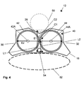
- Fig. 4 shows a sectional view of the container 12 of Figs. 1 to 3 taken along the line IV-IV in Fig. 1 .
- Fig. 4 is only directed to the container 12 (i.e., the strap system 14 has been omitted).
- FIG. 4 illustrates the three V-shaped recesses 28, 30, 32 for detachably accommodating fire extinguishing equipment such as a gas tank 50 filled with breathable air or pressurizing gas, or any other pressure source (e.g., a compressor) for pressurizing the fire extinguishing medium stored in the medium reservoir 40.
- a gas tank 50 filled with breathable air or pressurizing gas, or any other pressure source (e.g., a compressor) for pressurizing the fire extinguishing medium stored in the medium reservoir 40.
- a pressure source e.g., a compressor
- auxiliary pressure source can optionally be omitted.
- Fig. 4 also illustrates the fact that the shell 16 is concavely shaped on its side facing a user 52.
- Reference numeral C1 in Fig. 4 denotes the center of gravity of the medium reservoir 40 in the absence of the gas tank 50, and reference numeral C2 in the presence of the gas tank 50.
- the center of gravity C1, C2 of the medium reservoir is closer to its region facing the user 50 (and thus the strap system 14 not shown in Fig. 4 ) than to its lateral regions.
- This location of the center of gravity C1, C2 becomes apparent from a look on the envelope of the medium reservoir 40 comprising the two medium tanks 42, 44 each having a circular cross-section.
- the envelope of the two circular structures defining the location of the medium tanks 42, 44 will be an essentially oval structure with parallel sidewalls.
- the envelope has a first extension E1 in a direction generally towards the user 52 (and the associated strap system 14) and a second extension E2 perpendicular to the first extension E1.
- the second extension E2 is clearly larger than the first extension E1.
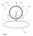
- Fig. 5 shows a sectional view similar to Fig. 4 of a conventional backpack type firefighting device comprising a single circular cylindrical medium tank 142 with two laterally attached gas tanks 150. As illustrated in Fig.
- the resulting length L3 of the lever arm extending between the back of the user 52 and the resulting center of gravity C3 is much longer than the corresponding lengths L1, L2 of the lever arms in the scenario illustrated in Fig. 4 .
- the shorter lever arm in the scenario of Fig. 4 makes the firefighting device as a whole easier to carry and easier to handle.
- the recess 28 is arranged in the shell 16 between the two adjacent medium tanks 42, 44 such that the recess 28 extends into the envelope of the two adjacent medium tanks 42, 44 (see Fig. 4 ).
- the gas tank 50 or any other fire extinguishing equipment can be brought closer to the back of the user 52, and the same applies to the corresponding center of gravity C2.
- the recess 28 is defined as an opening within the shell 16 or as having a cross-section in accordance with, for example, a U.
- each of the two medium tanks 42, 44 is provided with a respective outlet opening 42A, 44A capable of connecting the respective medium tank 42, 44 with a medium spreading device not illustrated in Fig. 4 .
- a pipe 54 arranged within the shell 16 between the two medium tanks 42, 44 connects a pressure source (e.g., the gas tank 50 when filled with pressurizing gas) with the medium tanks 42, 44.
- Pipe 54 ends in pipe system 46 (see Fig. 3 ).
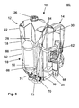
- Fig. 6 shows a first embodiment of a fully assembled firefighting device 60 comprising the base body 10 described above with reference to Figs. 1 to 4 .
- a gas tank 50 as well as a pistol-shaped medium spreading device 62 are detachably mounted to the container 12 of the base body 10.
- the body part 18 of the shell 16 is provided with a further attachment structure in the form of four spaced-apart slits 64 in the region of the recess 28 in which the gas tank 50 is to be accommodated (only two slits 64 are shown in the perspective view of Fig. 6 ).
- the gas tank 50 is held in the recess 28 by a complementary attachment structure in the form of two straps or bands 66 threaded through the slits 64 in the shell 16. Additionally, a removable holder 68 of a generally cylindrical shape is attached to the bottom part 20 of the shell 16 to removably accommodate the medium spreading device 62.
- the firefighting device 60 further comprises a pressure regulator 70 coupled to an outlet of the gas tank 50 filled with pressurizing gas.
- the pressure regulator 70 is connected via a first hose 72 to the pipe 54 (see Fig. 4 ) and via this pipe 54 to an inlet for pressurizing gas at the pipe system 46 of the medium reservoir 40 (not shown in Fig. 6 ).
- the pressure regulator 70 is also connected via a second hose 74 to the medium spreading device 62.
- the medium spreading device 62 is further connected via a third hose 76 to the outlet openings 42A, 44A for pressurized medium of the medium reservoir 40 (likewise not shown in Fig. 6 ).
- Fig. 7 shows a second embodiment of a fully assembled firefighting device 60 similar to the embodiment illustrated in Fig. 6 .
- the main difference between the embodiment of Fig. 6 and the embodiment of Fig. 7 resides in the fact that instead of a gas tank arranged centrally at the shell 16 (see reference numeral 50 in Fig. 6 ), in the embodiment of Fig. 7 two larger gas tanks 50' are detachably accommodated in the lateral recesses 28, 32 of the shell 16. Similar to the embodiment of Fig. 6 , attachment structures in the form of slits 64 provided in the shell 16 as well as bands or straps 66 extending through the slits 64 are used to secure the gas tanks 50' to the shell 16. As shown in Fig. 7 , the medium spreading device 62 is connected to only a single gas tank 50'. It thus becomes necessary to switch the pressure regulator 70 from the first gas tank 50' to the second gas tank 50' when the first gas tank 50' becomes empty.
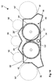
- Figs. 8 to 10 show sectional views of three further embodiments of containers 12 similar to Fig. 4 .
- the containers 12 of Figs. 8 to 10 may be used in a firefighting device similar to the firefighting device 60 illustrated in Figs. 6 and 7 .
- the shell 16 and the medium reservoir 40 form a one-piece structure.
- the shell 16 is still housing the medium reservoir 40 and provides the corresponding recesses 28, 30, 32 for accommodating fire extinguishing equipment such as a gas tank 50. Also maintained is the concavely shaped portion of the shell 16 that faces the back of the user as well as the stand portion (not shown in Fig. 8 ).
- the shape of the recesses 28, 30, 32 provided in the shell 16 has been changed compared to Fig. 4 .
- the V-shaped cross-section of the recesses 28, 30, 32 has been replaced with a curved, generally U-shaped cross-section.
- three gas tanks 50, 50' may be attached to the shell 16 in a combination of the embodiments illustrated in Figs. 6 and 7 .
- the smaller gas tank 50 may be filled with breathable air, and the two larger gas tanks 50' with pressurizing gas.
- the number of recesses provided in the shell 16 may be increased as necessary.
- the region of the shell 16 facing away from the user may be provided with altogether three recesses 28, 28', 28" so as to accommodate up to three gas tanks 50.
- the provision of a shell 16 for portably housing the medium reservoir 40 has a plurality of advantages, which need not all be realized in all configurations.
- the shell 16 permits to connect the medium reservoir 40 to the strap system 14.
- the shell 16 may be provided with a suitable attachment structure.
- the shell 16 permits to flexibly attach auxiliary fire extinguishing equipment such as a pressure source (e.g., one or more gas tanks 50, 50') or a spreading device 62 thereto.
- a pressure source e.g., one or more gas tanks 50, 50'
- a spreading device 62 e.g., a spreading device 62
- the shell 16 may be provided with one or more recesses 28, 28', 28", 30, 32 for a stable and thus secure accommodation of such equipment.
- the shell 16 may be shaped to conform to the back of the user to increase the wearing comfort. It will be appreciated that the above advantages can be realized in combination with various designs and structures of the shell 16 and the medium reservoir 40, so that the designs and structures discussed above in connection with the exemplary embodiments may not be construed to be of a limiting nature.
Landscapes
- Health & Medical Sciences (AREA)
- Public Health (AREA)
- Business, Economics & Management (AREA)
- Emergency Management (AREA)
- Respiratory Apparatuses And Protective Means (AREA)
Priority Applications (2)
| Application Number | Priority Date | Filing Date | Title |
|---|---|---|---|
| EP11000244.1A EP2476464B1 (de) | 2011-01-13 | 2011-01-13 | Rucksackartige Brandbekämpfungsvorrichtung und Behälter dafür |
| CN201210011226.2A CN102580276B (zh) | 2011-01-13 | 2012-01-13 | 背包式消防装置以及用于该消防装置的容器 |
Applications Claiming Priority (1)
| Application Number | Priority Date | Filing Date | Title |
|---|---|---|---|
| EP11000244.1A EP2476464B1 (de) | 2011-01-13 | 2011-01-13 | Rucksackartige Brandbekämpfungsvorrichtung und Behälter dafür |
Publications (2)
| Publication Number | Publication Date |
|---|---|
| EP2476464A1 true EP2476464A1 (de) | 2012-07-18 |
| EP2476464B1 EP2476464B1 (de) | 2018-11-14 |
Family
ID=44065448
Family Applications (1)
| Application Number | Title | Priority Date | Filing Date |
|---|---|---|---|
| EP11000244.1A Active EP2476464B1 (de) | 2011-01-13 | 2011-01-13 | Rucksackartige Brandbekämpfungsvorrichtung und Behälter dafür |
Country Status (2)
| Country | Link |
|---|---|
| EP (1) | EP2476464B1 (de) |
| CN (1) | CN102580276B (de) |
Cited By (1)
| Publication number | Priority date | Publication date | Assignee | Title |
|---|---|---|---|---|
| CN113864149A (zh) * | 2021-10-23 | 2021-12-31 | 浙江理工大学 | 一种背负式减重消防泵 |
Families Citing this family (1)
| Publication number | Priority date | Publication date | Assignee | Title |
|---|---|---|---|---|
| CN102908735B (zh) * | 2012-09-26 | 2015-09-16 | 江苏及时雨消防科技有限公司 | 新型电动背负式水系灭火器 |
Citations (3)
| Publication number | Priority date | Publication date | Assignee | Title |
|---|---|---|---|---|
| WO2000003763A1 (en) * | 1998-07-20 | 2000-01-27 | Intelagard, Inc. | Foam based product solution delivery apparatus |
| WO2006038046A1 (en) * | 2004-10-04 | 2006-04-13 | Zoran Bonacin | Compressed-air fire extinguisher |
| FR2926998A1 (fr) * | 2008-02-05 | 2009-08-07 | Vittorio Andre Blaise Albert Di | Procede et appareil de couplage d'extincteurs d'incendie |
Family Cites Families (8)
| Publication number | Priority date | Publication date | Assignee | Title |
|---|---|---|---|---|
| DE1708849C3 (de) * | 1957-08-02 | 1975-06-26 | Siegfried 6073 Egelsbach Ruhnke | Feuerbekämpfungsausrüstung |
| US3802511A (en) * | 1972-12-06 | 1974-04-09 | L Good | Portable fire extinguisher |
| US5469993A (en) * | 1993-12-02 | 1995-11-28 | Monsanto Company | Dispensing system |
| KR20020036468A (ko) * | 2000-11-10 | 2002-05-16 | 윤욱열 | 산불용 소화기 |
| JP4709171B2 (ja) * | 2003-05-09 | 2011-06-22 | ニューデルタ工業株式会社 | 背負式動力噴霧機 |
| JP4516481B2 (ja) * | 2004-06-02 | 2010-08-04 | セイコーエプソン株式会社 | 電気泳動粒子、その製造方法およびその用途 |
| CN2875502Y (zh) * | 2005-11-07 | 2007-03-07 | 天津泰瑞工贸有限公司 | 背负式灭火装置 |
| JP4997134B2 (ja) * | 2008-02-14 | 2012-08-08 | 株式会社 マルナカ | 背負式作業機 |
-
2011
- 2011-01-13 EP EP11000244.1A patent/EP2476464B1/de active Active
-
2012
- 2012-01-13 CN CN201210011226.2A patent/CN102580276B/zh active Active
Patent Citations (3)
| Publication number | Priority date | Publication date | Assignee | Title |
|---|---|---|---|---|
| WO2000003763A1 (en) * | 1998-07-20 | 2000-01-27 | Intelagard, Inc. | Foam based product solution delivery apparatus |
| WO2006038046A1 (en) * | 2004-10-04 | 2006-04-13 | Zoran Bonacin | Compressed-air fire extinguisher |
| FR2926998A1 (fr) * | 2008-02-05 | 2009-08-07 | Vittorio Andre Blaise Albert Di | Procede et appareil de couplage d'extincteurs d'incendie |
Cited By (1)
| Publication number | Priority date | Publication date | Assignee | Title |
|---|---|---|---|---|
| CN113864149A (zh) * | 2021-10-23 | 2021-12-31 | 浙江理工大学 | 一种背负式减重消防泵 |
Also Published As
| Publication number | Publication date |
|---|---|
| CN102580276B (zh) | 2017-05-31 |
| CN102580276A (zh) | 2012-07-18 |
| EP2476464B1 (de) | 2018-11-14 |
Similar Documents
| Publication | Publication Date | Title |
|---|---|---|
| US3802511A (en) | Portable fire extinguisher | |
| US8136702B2 (en) | Pressurized hydration system | |
| US8540122B2 (en) | Pressurized hydration system | |
| ES2707287T3 (es) | Aparato extintor de incendios a base de agua/espuma con consistencia ajustable de la espuma | |
| US20180071760A1 (en) | Portable fluid dispensing system | |
| US20080172826A1 (en) | Backpack having a reservoir | |
| US6793428B2 (en) | Drywall joint compound applicator appliance | |
| CN102858409A (zh) | 铰接式消防员呼吸包 | |
| US20050111995A1 (en) | Carbon dioxide power system and method | |
| US7631672B2 (en) | Portable hydration system with resupply system | |
| EP2476464B1 (de) | Rucksackartige Brandbekämpfungsvorrichtung und Behälter dafür | |
| ES2262661T3 (es) | Valvula de control de fluidos destinada a un recipiente de presion. | |
| US20130118636A1 (en) | Balloon inflator | |
| BR112013029997B1 (pt) | Aparelho respiratório autônomo | |
| US20210078026A1 (en) | Backpack Mister | |
| WO2010019821A1 (en) | Hydration system for kayak integration | |
| US20150076180A1 (en) | Multi-chamber fluid containers | |
| CA3033008A1 (en) | Air cylinder cart with manifold for supplying one or two control panels | |
| ES2839074T3 (es) | Adaptador de dispensación para espuma de poliuretano monocomponente | |
| US20060144862A1 (en) | Lightweight, portable, collapsible, pressurized fluid delivery system for on demand use by hikers, runners, bikers, or other applications where periodic hydration is necessary | |
| US20060144863A1 (en) | Flexible compression unit for on demand, portable, collapsible fluid delivery systems | |
| KR101131195B1 (ko) | 가압식 중공사막 수중 호흡장치 | |
| US20230173516A1 (en) | Hand piece for aesthetic and medical device | |
| KR20190017963A (ko) | 소화기 | |
| KR200408953Y1 (ko) | 산불진화장비 수납용 배낭 |
Legal Events
| Date | Code | Title | Description |
|---|---|---|---|
| PUAI | Public reference made under article 153(3) epc to a published international application that has entered the european phase |
Free format text: ORIGINAL CODE: 0009012 |
|
| 17P | Request for examination filed |
Effective date: 20111007 |
|
| AK | Designated contracting states |
Kind code of ref document: A1 Designated state(s): AL AT BE BG CH CY CZ DE DK EE ES FI FR GB GR HR HU IE IS IT LI LT LU LV MC MK MT NL NO PL PT RO RS SE SI SK SM TR |
|
| AX | Request for extension of the european patent |
Extension state: BA ME |
|
| STAA | Information on the status of an ep patent application or granted ep patent |
Free format text: STATUS: EXAMINATION IS IN PROGRESS |
|
| 17Q | First examination report despatched |
Effective date: 20170330 |
|
| GRAP | Despatch of communication of intention to grant a patent |
Free format text: ORIGINAL CODE: EPIDOSNIGR1 |
|
| STAA | Information on the status of an ep patent application or granted ep patent |
Free format text: STATUS: GRANT OF PATENT IS INTENDED |
|
| INTG | Intention to grant announced |
Effective date: 20180417 |
|
| GRAS | Grant fee paid |
Free format text: ORIGINAL CODE: EPIDOSNIGR3 |
|
| GRAJ | Information related to disapproval of communication of intention to grant by the applicant or resumption of examination proceedings by the epo deleted |
Free format text: ORIGINAL CODE: EPIDOSDIGR1 |
|
| GRAL | Information related to payment of fee for publishing/printing deleted |
Free format text: ORIGINAL CODE: EPIDOSDIGR3 |
|
| STAA | Information on the status of an ep patent application or granted ep patent |
Free format text: STATUS: EXAMINATION IS IN PROGRESS |
|
| INTC | Intention to grant announced (deleted) | ||
| GRAR | Information related to intention to grant a patent recorded |
Free format text: ORIGINAL CODE: EPIDOSNIGR71 |
|
| STAA | Information on the status of an ep patent application or granted ep patent |
Free format text: STATUS: GRANT OF PATENT IS INTENDED |
|
| GRAA | (expected) grant |
Free format text: ORIGINAL CODE: 0009210 |
|
| STAA | Information on the status of an ep patent application or granted ep patent |
Free format text: STATUS: THE PATENT HAS BEEN GRANTED |
|
| AK | Designated contracting states |
Kind code of ref document: B1 Designated state(s): AL AT BE BG CH CY CZ DE DK EE ES FI FR GB GR HR HU IE IS IT LI LT LU LV MC MK MT NL NO PL PT RO RS SE SI SK SM TR |
|
| INTG | Intention to grant announced |
Effective date: 20181005 |
|
| REG | Reference to a national code |
Ref country code: GB Ref legal event code: FG4D |
|
| REG | Reference to a national code |
Ref country code: CH Ref legal event code: EP Ref country code: AT Ref legal event code: REF Ref document number: 1064118 Country of ref document: AT Kind code of ref document: T Effective date: 20181115 |
|
| REG | Reference to a national code |
Ref country code: DE Ref legal event code: R096 Ref document number: 602011053782 Country of ref document: DE |
|
| REG | Reference to a national code |
Ref country code: IE Ref legal event code: FG4D |
|
| REG | Reference to a national code |
Ref country code: NL Ref legal event code: MP Effective date: 20181114 |
|
| REG | Reference to a national code |
Ref country code: LT Ref legal event code: MG4D |
|
| REG | Reference to a national code |
Ref country code: AT Ref legal event code: MK05 Ref document number: 1064118 Country of ref document: AT Kind code of ref document: T Effective date: 20181114 |
|
| PG25 | Lapsed in a contracting state [announced via postgrant information from national office to epo] |
Ref country code: FI Free format text: LAPSE BECAUSE OF FAILURE TO SUBMIT A TRANSLATION OF THE DESCRIPTION OR TO PAY THE FEE WITHIN THE PRESCRIBED TIME-LIMIT Effective date: 20181114 Ref country code: BG Free format text: LAPSE BECAUSE OF FAILURE TO SUBMIT A TRANSLATION OF THE DESCRIPTION OR TO PAY THE FEE WITHIN THE PRESCRIBED TIME-LIMIT Effective date: 20190214 Ref country code: NO Free format text: LAPSE BECAUSE OF FAILURE TO SUBMIT A TRANSLATION OF THE DESCRIPTION OR TO PAY THE FEE WITHIN THE PRESCRIBED TIME-LIMIT Effective date: 20190214 Ref country code: LT Free format text: LAPSE BECAUSE OF FAILURE TO SUBMIT A TRANSLATION OF THE DESCRIPTION OR TO PAY THE FEE WITHIN THE PRESCRIBED TIME-LIMIT Effective date: 20181114 Ref country code: IS Free format text: LAPSE BECAUSE OF FAILURE TO SUBMIT A TRANSLATION OF THE DESCRIPTION OR TO PAY THE FEE WITHIN THE PRESCRIBED TIME-LIMIT Effective date: 20190314 Ref country code: LV Free format text: LAPSE BECAUSE OF FAILURE TO SUBMIT A TRANSLATION OF THE DESCRIPTION OR TO PAY THE FEE WITHIN THE PRESCRIBED TIME-LIMIT Effective date: 20181114 Ref country code: AT Free format text: LAPSE BECAUSE OF FAILURE TO SUBMIT A TRANSLATION OF THE DESCRIPTION OR TO PAY THE FEE WITHIN THE PRESCRIBED TIME-LIMIT Effective date: 20181114 Ref country code: ES Free format text: LAPSE BECAUSE OF FAILURE TO SUBMIT A TRANSLATION OF THE DESCRIPTION OR TO PAY THE FEE WITHIN THE PRESCRIBED TIME-LIMIT Effective date: 20181114 Ref country code: HR Free format text: LAPSE BECAUSE OF FAILURE TO SUBMIT A TRANSLATION OF THE DESCRIPTION OR TO PAY THE FEE WITHIN THE PRESCRIBED TIME-LIMIT Effective date: 20181114 |
|
| PG25 | Lapsed in a contracting state [announced via postgrant information from national office to epo] |
Ref country code: PT Free format text: LAPSE BECAUSE OF FAILURE TO SUBMIT A TRANSLATION OF THE DESCRIPTION OR TO PAY THE FEE WITHIN THE PRESCRIBED TIME-LIMIT Effective date: 20190314 Ref country code: AL Free format text: LAPSE BECAUSE OF FAILURE TO SUBMIT A TRANSLATION OF THE DESCRIPTION OR TO PAY THE FEE WITHIN THE PRESCRIBED TIME-LIMIT Effective date: 20181114 Ref country code: SE Free format text: LAPSE BECAUSE OF FAILURE TO SUBMIT A TRANSLATION OF THE DESCRIPTION OR TO PAY THE FEE WITHIN THE PRESCRIBED TIME-LIMIT Effective date: 20181114 Ref country code: GR Free format text: LAPSE BECAUSE OF FAILURE TO SUBMIT A TRANSLATION OF THE DESCRIPTION OR TO PAY THE FEE WITHIN THE PRESCRIBED TIME-LIMIT Effective date: 20190215 Ref country code: RS Free format text: LAPSE BECAUSE OF FAILURE TO SUBMIT A TRANSLATION OF THE DESCRIPTION OR TO PAY THE FEE WITHIN THE PRESCRIBED TIME-LIMIT Effective date: 20181114 Ref country code: NL Free format text: LAPSE BECAUSE OF FAILURE TO SUBMIT A TRANSLATION OF THE DESCRIPTION OR TO PAY THE FEE WITHIN THE PRESCRIBED TIME-LIMIT Effective date: 20181114 |
|
| PG25 | Lapsed in a contracting state [announced via postgrant information from national office to epo] |
Ref country code: IT Free format text: LAPSE BECAUSE OF FAILURE TO SUBMIT A TRANSLATION OF THE DESCRIPTION OR TO PAY THE FEE WITHIN THE PRESCRIBED TIME-LIMIT Effective date: 20181114 Ref country code: DK Free format text: LAPSE BECAUSE OF FAILURE TO SUBMIT A TRANSLATION OF THE DESCRIPTION OR TO PAY THE FEE WITHIN THE PRESCRIBED TIME-LIMIT Effective date: 20181114 Ref country code: PL Free format text: LAPSE BECAUSE OF FAILURE TO SUBMIT A TRANSLATION OF THE DESCRIPTION OR TO PAY THE FEE WITHIN THE PRESCRIBED TIME-LIMIT Effective date: 20181114 Ref country code: CZ Free format text: LAPSE BECAUSE OF FAILURE TO SUBMIT A TRANSLATION OF THE DESCRIPTION OR TO PAY THE FEE WITHIN THE PRESCRIBED TIME-LIMIT Effective date: 20181114 |
|
| REG | Reference to a national code |
Ref country code: DE Ref legal event code: R097 Ref document number: 602011053782 Country of ref document: DE |
|
| PG25 | Lapsed in a contracting state [announced via postgrant information from national office to epo] |
Ref country code: EE Free format text: LAPSE BECAUSE OF FAILURE TO SUBMIT A TRANSLATION OF THE DESCRIPTION OR TO PAY THE FEE WITHIN THE PRESCRIBED TIME-LIMIT Effective date: 20181114 Ref country code: SM Free format text: LAPSE BECAUSE OF FAILURE TO SUBMIT A TRANSLATION OF THE DESCRIPTION OR TO PAY THE FEE WITHIN THE PRESCRIBED TIME-LIMIT Effective date: 20181114 Ref country code: RO Free format text: LAPSE BECAUSE OF FAILURE TO SUBMIT A TRANSLATION OF THE DESCRIPTION OR TO PAY THE FEE WITHIN THE PRESCRIBED TIME-LIMIT Effective date: 20181114 Ref country code: MC Free format text: LAPSE BECAUSE OF FAILURE TO SUBMIT A TRANSLATION OF THE DESCRIPTION OR TO PAY THE FEE WITHIN THE PRESCRIBED TIME-LIMIT Effective date: 20181114 Ref country code: SK Free format text: LAPSE BECAUSE OF FAILURE TO SUBMIT A TRANSLATION OF THE DESCRIPTION OR TO PAY THE FEE WITHIN THE PRESCRIBED TIME-LIMIT Effective date: 20181114 |
|
| REG | Reference to a national code |
Ref country code: CH Ref legal event code: PL |
|
| PLBE | No opposition filed within time limit |
Free format text: ORIGINAL CODE: 0009261 |
|
| STAA | Information on the status of an ep patent application or granted ep patent |
Free format text: STATUS: NO OPPOSITION FILED WITHIN TIME LIMIT |
|
| PG25 | Lapsed in a contracting state [announced via postgrant information from national office to epo] |
Ref country code: LU Free format text: LAPSE BECAUSE OF NON-PAYMENT OF DUE FEES Effective date: 20190113 |
|
| REG | Reference to a national code |
Ref country code: BE Ref legal event code: MM Effective date: 20190131 |
|
| 26N | No opposition filed |
Effective date: 20190815 |
|
| GBPC | Gb: european patent ceased through non-payment of renewal fee |
Effective date: 20190214 |
|
| REG | Reference to a national code |
Ref country code: IE Ref legal event code: MM4A |
|
| PG25 | Lapsed in a contracting state [announced via postgrant information from national office to epo] |
Ref country code: FR Free format text: LAPSE BECAUSE OF NON-PAYMENT OF DUE FEES Effective date: 20190114 Ref country code: SI Free format text: LAPSE BECAUSE OF FAILURE TO SUBMIT A TRANSLATION OF THE DESCRIPTION OR TO PAY THE FEE WITHIN THE PRESCRIBED TIME-LIMIT Effective date: 20181114 |
|
| PG25 | Lapsed in a contracting state [announced via postgrant information from national office to epo] |
Ref country code: BE Free format text: LAPSE BECAUSE OF NON-PAYMENT OF DUE FEES Effective date: 20190131 |
|
| PG25 | Lapsed in a contracting state [announced via postgrant information from national office to epo] |
Ref country code: CH Free format text: LAPSE BECAUSE OF NON-PAYMENT OF DUE FEES Effective date: 20190131 Ref country code: LI Free format text: LAPSE BECAUSE OF NON-PAYMENT OF DUE FEES Effective date: 20190131 |
|
| PG25 | Lapsed in a contracting state [announced via postgrant information from national office to epo] |
Ref country code: GB Free format text: LAPSE BECAUSE OF NON-PAYMENT OF DUE FEES Effective date: 20190214 Ref country code: IE Free format text: LAPSE BECAUSE OF NON-PAYMENT OF DUE FEES Effective date: 20190113 |
|
| PG25 | Lapsed in a contracting state [announced via postgrant information from national office to epo] |
Ref country code: TR Free format text: LAPSE BECAUSE OF FAILURE TO SUBMIT A TRANSLATION OF THE DESCRIPTION OR TO PAY THE FEE WITHIN THE PRESCRIBED TIME-LIMIT Effective date: 20181114 |
|
| PG25 | Lapsed in a contracting state [announced via postgrant information from national office to epo] |
Ref country code: MT Free format text: LAPSE BECAUSE OF NON-PAYMENT OF DUE FEES Effective date: 20190113 |
|
| PG25 | Lapsed in a contracting state [announced via postgrant information from national office to epo] |
Ref country code: CY Free format text: LAPSE BECAUSE OF FAILURE TO SUBMIT A TRANSLATION OF THE DESCRIPTION OR TO PAY THE FEE WITHIN THE PRESCRIBED TIME-LIMIT Effective date: 20181114 |
|
| PG25 | Lapsed in a contracting state [announced via postgrant information from national office to epo] |
Ref country code: HU Free format text: LAPSE BECAUSE OF FAILURE TO SUBMIT A TRANSLATION OF THE DESCRIPTION OR TO PAY THE FEE WITHIN THE PRESCRIBED TIME-LIMIT; INVALID AB INITIO Effective date: 20110113 |
|
| PG25 | Lapsed in a contracting state [announced via postgrant information from national office to epo] |
Ref country code: MK Free format text: LAPSE BECAUSE OF FAILURE TO SUBMIT A TRANSLATION OF THE DESCRIPTION OR TO PAY THE FEE WITHIN THE PRESCRIBED TIME-LIMIT Effective date: 20181114 |
|
| PGFP | Annual fee paid to national office [announced via postgrant information from national office to epo] |
Ref country code: DE Payment date: 20251203 Year of fee payment: 16 |