EP2476497A1 - Schneideverfahren und schneidevorrichtung - Google Patents
Schneideverfahren und schneidevorrichtung Download PDFInfo
- Publication number
- EP2476497A1 EP2476497A1 EP10850197A EP10850197A EP2476497A1 EP 2476497 A1 EP2476497 A1 EP 2476497A1 EP 10850197 A EP10850197 A EP 10850197A EP 10850197 A EP10850197 A EP 10850197A EP 2476497 A1 EP2476497 A1 EP 2476497A1
- Authority
- EP
- European Patent Office
- Prior art keywords
- work
- cutting
- machining
- groove
- point
- Prior art date
- Legal status (The legal status is an assumption and is not a legal conclusion. Google has not performed a legal analysis and makes no representation as to the accuracy of the status listed.)
- Granted
Links
Images











Classifications
-
- B—PERFORMING OPERATIONS; TRANSPORTING
- B23—MACHINE TOOLS; METAL-WORKING NOT OTHERWISE PROVIDED FOR
- B23C—MILLING
- B23C3/00—Milling particular work; Special milling operations; Machines therefor
- B23C3/28—Grooving workpieces
- B23C3/34—Milling grooves of other forms, e.g. circumferential
-
- B—PERFORMING OPERATIONS; TRANSPORTING
- B23—MACHINE TOOLS; METAL-WORKING NOT OTHERWISE PROVIDED FOR
- B23C—MILLING
- B23C5/00—Milling-cutters
- B23C5/02—Milling-cutters characterised by the shape of the cutter
-
- Y—GENERAL TAGGING OF NEW TECHNOLOGICAL DEVELOPMENTS; GENERAL TAGGING OF CROSS-SECTIONAL TECHNOLOGIES SPANNING OVER SEVERAL SECTIONS OF THE IPC; TECHNICAL SUBJECTS COVERED BY FORMER USPC CROSS-REFERENCE ART COLLECTIONS [XRACs] AND DIGESTS
- Y10—TECHNICAL SUBJECTS COVERED BY FORMER USPC
- Y10T—TECHNICAL SUBJECTS COVERED BY FORMER US CLASSIFICATION
- Y10T409/00—Gear cutting, milling, or planing
- Y10T409/30—Milling
- Y10T409/303752—Process
- Y10T409/303808—Process including infeeding
-
- Y—GENERAL TAGGING OF NEW TECHNOLOGICAL DEVELOPMENTS; GENERAL TAGGING OF CROSS-SECTIONAL TECHNOLOGIES SPANNING OVER SEVERAL SECTIONS OF THE IPC; TECHNICAL SUBJECTS COVERED BY FORMER USPC CROSS-REFERENCE ART COLLECTIONS [XRACs] AND DIGESTS
- Y10—TECHNICAL SUBJECTS COVERED BY FORMER USPC
- Y10T—TECHNICAL SUBJECTS COVERED BY FORMER US CLASSIFICATION
- Y10T409/00—Gear cutting, milling, or planing
- Y10T409/30—Milling
- Y10T409/304424—Means for internal milling
-
- Y—GENERAL TAGGING OF NEW TECHNOLOGICAL DEVELOPMENTS; GENERAL TAGGING OF CROSS-SECTIONAL TECHNOLOGIES SPANNING OVER SEVERAL SECTIONS OF THE IPC; TECHNICAL SUBJECTS COVERED BY FORMER USPC CROSS-REFERENCE ART COLLECTIONS [XRACs] AND DIGESTS
- Y10—TECHNICAL SUBJECTS COVERED BY FORMER USPC
- Y10T—TECHNICAL SUBJECTS COVERED BY FORMER US CLASSIFICATION
- Y10T409/00—Gear cutting, milling, or planing
- Y10T409/30—Milling
- Y10T409/304536—Milling including means to infeed work to cutter
- Y10T409/305544—Milling including means to infeed work to cutter with work holder
- Y10T409/305656—Milling including means to infeed work to cutter with work holder including means to support work for rotation during operation
-
- Y—GENERAL TAGGING OF NEW TECHNOLOGICAL DEVELOPMENTS; GENERAL TAGGING OF CROSS-SECTIONAL TECHNOLOGIES SPANNING OVER SEVERAL SECTIONS OF THE IPC; TECHNICAL SUBJECTS COVERED BY FORMER USPC CROSS-REFERENCE ART COLLECTIONS [XRACs] AND DIGESTS
- Y10—TECHNICAL SUBJECTS COVERED BY FORMER USPC
- Y10T—TECHNICAL SUBJECTS COVERED BY FORMER US CLASSIFICATION
- Y10T409/00—Gear cutting, milling, or planing
- Y10T409/30—Milling
- Y10T409/306664—Milling including means to infeed rotary cutter toward work
- Y10T409/30672—Milling including means to infeed rotary cutter toward work with means to limit penetration into work
-
- Y—GENERAL TAGGING OF NEW TECHNOLOGICAL DEVELOPMENTS; GENERAL TAGGING OF CROSS-SECTIONAL TECHNOLOGIES SPANNING OVER SEVERAL SECTIONS OF THE IPC; TECHNICAL SUBJECTS COVERED BY FORMER USPC CROSS-REFERENCE ART COLLECTIONS [XRACs] AND DIGESTS
- Y10—TECHNICAL SUBJECTS COVERED BY FORMER USPC
- Y10T—TECHNICAL SUBJECTS COVERED BY FORMER US CLASSIFICATION
- Y10T409/00—Gear cutting, milling, or planing
- Y10T409/30—Milling
- Y10T409/306664—Milling including means to infeed rotary cutter toward work
- Y10T409/307672—Angularly adjustable cutter head
Definitions
- the present invention relates to a cutting machining method for a lathe and a cutting machining apparatus, and in particular, relates to a technology to remarkably improve machining accuracy and machining efficiency of a groove without having tool lifetime be shortened even when a work, such as rotating parts of a jet-engine for an airplane, which is particularly made of difficult-to-machine material is lathed to have a circular or arc-like groove.
- arc-like groove machining is required to be performed against a disc-shaped work as being hatched with broken lines.
- machining methods such as machining with a turning tool, machining with an end mill, machining with a milling cutter and machining with a side cutter have been utilized and appropriately adopted corresponding to work material, dimensions of a machining groove, required machining accuracy or the like.
- machining a work made of difficult-to-cut material particularly such as titanium alloy and nickel-base alloy following problems have occurred respectively.
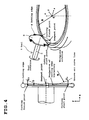
- FIGS. 4 to 6 illustrate how a groove is formed by actual machining in a case that machining is performed against a work W by utilizing a side cutter as target machining shape being a circumferential groove at predetermined radius with a vertical side wall.
- a side cutter 1 cutting edges 4 are arranged at even intervals on an outer circumference of a disc 3 of which center is matched with the center of a shaft 2.
- the shaft 2 is lowered as being maintained continuously in parallel to the work W rotating in the counterclockwise direction.
- FIG. 4 The left side of FIG. 4 is a plane view illustrating a state that the cutting edge 4 enters into the work most deeply.
- a cutting start point is a position at which contacting to the work W is started at the most upstream side as viewing from the rotation direction of the disc 3.
- a cutting finish point is a position being an exit from the work W at the most downstream side, as viewing from the rotation direction of the disc 3, of a cutting edge trajectory after passing through a most deeply entering position in the work.
- the most deeply entering position in the work is called the deepest point of the cutting edge trajectory.
- the groove is gradually formed as the deepest point being on an inner diameter and the cutting start point and the cutting finish point being on an outer diameter as viewing the end face of the work W from the plane.
- the groove is not formed in parallel to the center line of the work W in radially sectioned shape. That is, in FIG. 4 , a kerf on the end face of the work W is to be a line connecting the cutting start point and the cutting finish point.
- the cutting edge 4 passes through the inside of the work W being on a trajectory as a chord connecting the cutting start point and the cutting finish point having the midpoint of the chord being at the deepest point.
- the groove machining is performed until groove depth of the machining target is obtained as rotating the work W on the center point O while maintaining the shaft 2 continuously in parallel to the work W. Consequently, the sectional shape of the groove is to be determined with one turn of the work W on the center O against a cutting edge arc face of which chord is the line connecting the cutting start point and the cutting finish point as the midpoint of the chord being the deepest point within the work W.
- a point on a tool trajectory projected on the machining face is to be apart from the arc curve of the groove toward the outer side of the groove by ⁇ in a direction of an axis (hereinafter, the axis is defined as x-axis) which is obtained as projecting, on the work face, a straight line from the deepest point of the cutting edge 4 in the work to the center axis of the work W, as illustrated in the plane view at the left side of FIG. 4 .
- x-axis is matched with the shaft 2 of the side cutter 1 as being fixed regardless of the work rotation during machining.
- NC numerical control
- the machine coordinate system of (1) is adopted in the present invention. Accordingly, the original point is continuously located at the same position and the x-axis direction is not varied regardless of the work rotation.
- ⁇ denotes deviation occurring in the x-axis direction between the projected tool trajectory at each point on the tool trajectory and the arc curve of the groove being the target shape as tracing the projected tool trajectory from the cutting start point to the deepest point or from the deepest point to the cutting finish point.
- Difference between the tool trajectory and the groove arc at the cutting start point is denoted by ⁇ s and difference between the tool trajectory and the groove arc at the cutting finish point is denoted by ⁇ f.
- the deviation ⁇ is to be the maximum value at the cutting start point ⁇ s and the cutting finish point ⁇ f. Then, the larger the cutting edge radius of the side cutter 1 against the machining target radius is or the larger the groove depth of the machining target is, the larger the deviation ⁇ becomes. In this manner, the projected trajectory of the cutting edge is to be apart outside from the groove arc curve. Further, the entering depth of the cutting edge becomes deep from zero to the deepest point in an arc-like manner from the cutting start point to the deepest point. On the contrary, the entering depth of the cutting edge becomes shallow in an arc-like manner from the deepest point to the cutting finish point. Accordingly, as illustrated in FIG. 5 , at the time when the machining is completed, the sectional shape of the machined groove has a curve-face-like bank occurring at an outer wall part thereof so that groove width is lessened in the depth direction.
- the machining target shape of the groove is a true circle having a side face perpendicular to a work.
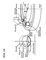
- the trajectory of the side cutter is denoted by 1
- the groove arc on the work face of the machining target shape is denoted by 2
- the trajectory of the groove arc of the machining target shape at arbitrary depth from the work face is denoted by 3 to 5
- the trajectory of the groove arc at the deepest point of the machining target shape is denoted by 6.
- a point on the face of the work W on which the deepest point 22 is projected is assumed to be an original point O'
- an axis oriented toward the work center axis from the original point O' in parallel to the work face is assumed to be x-axis
- an axis being perpendicular to x-axis on the horizontal plane is assumed to be y-axis
- an axis being vertically perpendicular to x-axis is assumed to be z-axis.
- arbitrary points on the groove arc trajectory of the machining target shape respectively at certain depth are denoted by 7 to 10.
- points on the cutting edge trajectory 1 at positions corresponding in the y-axis direction to the respective points 7 to 10 on a plane perpendicular to z-axis are denoted by 11 to 14.
- line segments respectively connecting 7 with 11, 8 with 12, 9 with 13, and 10 with 14 denote the deviation ⁇ in the x-axis direction between the abovementioned cutting edge trajectory and the groove arc of the machining target shape.
- length of the line segment connecting 7 with 11 is to be the deviation ⁇ f between the cutting edge trajectory and the groove arc of the machining target shape at the cutting finish point.
- arcs 15 to 18 passing through the points 11 to 14 are drawn around the center axis of the work W in a section being parallel to the work W face, that is, in a section being perpendicular to z-axis.
- a curve line connecting the points 23, 26 and 22 is to be a bank curve line at the outer wall occurring when the groove is machined with the side cutter type. The above becomes an error against the groove arc of the machining target shape.
- the shaft 2 of the tool 1 is lowered to be close to the work W as being continuously maintained in parallel. Accordingly, as illustrated in FIG. 7 , with the work W having a protruded portion at the front side of a machining groove and the like, there occurs interference between the shaft 2 and the protruded portion causing a problem that it is impossible to machine a groove having predetermined depth or deeper.
- the present invention when cutting an abovementioned work to form a circular or arc-like groove, the present invention reduces or prevents bank occurrence with higher accuracy of groove shape while utilizing advantage of low heat buildup and elongated tool lifetime of machining with a side cutter. In addition, the present invention ensures sufficient groove depth while avoiding interference with a work even when a small-diameter tool is used.
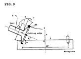
- the present inventers focused on that difference between the above cutting edge trajectory occurring in the x-axis direction and a groove arc of a machining target shape or the deviation ⁇ can be arbitrarily set by forming the cutting edge trajectory within a work to be an ellipse viewing in a plane view as devising shapes of the tool and cutting edge as needed while inclining a rotating shaft of the tool against a work end face.
- cutting machining methods as described in the following are adopted to the present invention.
- the above equation for calculating the deviation ⁇ in the x-axis direction expresses deviation ⁇ s, ⁇ f in the x-axis direction between the cutting edge trajectory and the groove arc at the cutting start point or the cutting finish point.
- the equation for calculating the deviation ⁇ in the x-axis direction expresses the deviation in the x-axis direction between the cutting edge trajectory and the groove arc at the deepest point.
- ⁇ necessarily becomes to zero enabling to perform machining so that the cutting edge trajectory and the groove arc are matched at the deepest point.
- ⁇ is expressed as a function of the tool diameter d, the depth t at an arbitrary point on the cutting edge trajectory, and the inclination angle B of the tool.
- ⁇ has a negative value
- the cutting edge trajectory is projected on the outer side of the groove arc.
- ⁇ has a positive value
- the cutting edge trajectory is projected on the inner side of the groove arc.
- the inclination angle B of the tool When the inclination angle B of the tool is zero, it is to be the side cutter type in which the tool shaft is parallel to the work face. When the inclination angle B of the tool is enlarged, the cutting edge trajectory projected on the work face is shifted to the inner side of the groove arc.
- ⁇ of each point in the entire area (0 ⁇ t ⁇ a d ) of the cutting edge trajectory relating to cutting is grouped into any one of the following three cases depending on magnitude of the inclination angle B of the tool.
- the cutting edge trajectory projected on the work face is projected on the inner side of the groove arc at the vicinities of the cutting start point and the cutting finish point and the cutting edge trajectory is projected on the outer side of the groove arc at the vicinity of the deepest point.
- banks occur at both inner side and outer side of the groove.
- the abovementioned deviation ⁇ occurring in the x-axis direction can be set to an arbitrary value by inclining at a predetermined angle with respect to the work end face so that a contacting point between the cutting edge of the cutting tool and the work is located downward and arranging the cutting edge trajectory to be an ellipse of which minor axis is oriented in the radial direction connecting the deepest point and the center O of the work. Accordingly, machining can be actualized at high accuracy even when the machining target shape is a groove having a vertical side wall, for example.
- the deviation ⁇ occurring in the x-axis direction can be easily calculated and optimal inclination angle can be selected.
- the cutting machining method of the above (3) it becomes possible to adjust the shape of the bank occurring at the outer circumferential wall or the inner circumferential wall of the groove by selecting a value of the deviation ⁇ at the cutting start point, cutting finish point or between the cutting start point and the cutting finish point among the deviation ⁇ .
- the cutting machining apparatus is provided with cutting tool inclining means which downwardly inclines the rotating shaft of the cutting tool toward the inner side of the work at a predetermined inclination angle, the inclination angle can be freely and continuously adjusted and the cutting machining methods of the above (1) to (5) can be actualized easily and effectively.
- the cutting edge is attached to the distal end of the spreading portion which spreads from the rotating shaft, it becomes possible to perform machining of a deeper groove while preventing interference between the tool and the work.
- FIG. 8 respectively illustrates a perspective view and a plane view when machining is performed with a tool 5 of the present invention on a work W to form a circumferential groove which is a target shape.
- the tool 5 of the present invention is constituted with a rotating shaft 6, a spread portion 7 of which center axis is matched with the rotating shaft 6 and which gradually spreads being trumpet-shaped (e.g., being top-flat conical), and cutting edges 8 which are placed at an outer circumferential end part of the spread portion 7 at even intervals.
- the rotating shaft 5 is extended toward an outer circumferential side of the work W having an angle B against an end face of the work W.
- the tool 5 is rotationally driven at high speed by a machining machine (not illustrated) in the counterclockwise direction when viewing the rotating shaft 6 axially from the center O side of the work W. Positioning thereof can be performed so as to freely determine a position from the center O of the work W, depth of cut, and further the abovementioned inclination angle are freely to be arranged.
- the work W is held on a machining table (not illustrated) and is also rotationally driven in the counterclockwise direction in FIG. 8 .
- the tool having the spread portion 7 is utilized.
- a groove shape i.e., depth and width
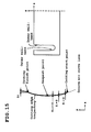
- FIG. 8 illustrates a state that the cutting edge 8 of the tool 5 reaches the deepest point.
- the cutting edges 8 are placed at the outer circumferential end of the spread portion 7 and are rotated at high speed on a circular trajectory having the rotating shaft 5 as the center.
- a cutting start point and a cutting finish point form an ellipse of which minor axis is oriented in the radial direction connecting the deepest point and the center O of the work W. As illustrated in FIG.
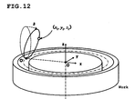
- a contacting point between the work face and the cutting edge trajectory of the cutting edge 8 right before cutting of the work W with the cutting edge 8 is assumed to be an original point O'
- an axis oriented toward the center point O from the original point O' along the work face is assumed to be x-axis
- an axis being perpendicular to x-axis at the original point O' on the horizontal plane is assumed to be y-axis
- an axis being vertically perpendicular thereto at the original point O' is assumed to be z-axis.
- a trajectory of a point (x 1 , y 1 , z 1 ) having an angle ⁇ from an uppermost point of the cutting edge can be expressed as follows.
- x 1 0
- the point (x 1 , y 1 , z 1 ) of angle ⁇ varies as follows.
- x 2 x 1 ⁇ cosB + z 1 ⁇ sinB
- the point (x 1 , y 1 , z 1 ) of angle ⁇ can be expressed as follows by utilizing the tool diameter d, the angle ⁇ from an uppermost point of the cutting edge, and inclination angle ⁇ .
- x 2 d / 2 ⁇ cos ⁇ + 1 ⁇ sinB
- the cutting edge trajectory projected on the work face is indicated by x 2 and y 2 .
- a projected ellipse trajectory of the tool is expressed as follows.
- x 2 d / 2 ⁇ cos ⁇ + 1 ⁇ sinB
- y 2 d / 2 ⁇ sin ⁇ a ⁇ s , cos ⁇ ⁇ 2 ⁇ t ⁇ / d ⁇ cosB - 1
- the angle ⁇ of the cutting edge trajectory is expressed as the following equation 4 by utilizing z 2 .
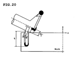
- the groove being the machining target is narrow and deep, when a side cutter having a flat tool bottom face to which a cutting edge is attached is utilized, the groove having desired depth cannot be formed owing to interference of the tool bottom plate with the formed groove as illustrated in FIG. 19 .
- a shape of the tool is only required to set the diameter of the spreading portion of the tool as large as possible and have the angle of the spread portion be selected so as to be perpendicular to a work when the rotating shaft of the tool is inclined, as illustrated in FIG. 20 .
- cutting edges of a circular type are utilized.
- FIG. 21 illustrates a flowchart for determining a cutting edge size, a tool diameter d, an inclination angle B, shape (an angle) of the spread portion, and a tool pass.
- the width w, diameter D and depth a d of a groove to be formed are inputted in step 1 and a cutting edge (i.e., an insert) of which size is equal to or smaller than the groove width is selected in step 2.
- a cutting edge i.e., an insert
- an allowable range of the tool inclination angle B i.e., Bmax and Bmin
- step 5 the angle of the spreading portion corresponding to the tool inclination angle B is determined, and then, dw is determined so that "L > a d " is satisfied.
- the tool inclination angle and the tool pass are determined in the range of "Bmin ⁇ B ⁇ Bmax" and machining is performed in step 6. At that time, while interference is checked, it is only required to set B to be close to Bmax for finishing the outer wall with the tool (i.e., to prevent interference between the tool outer face and the groove outer wall) and to set B to be close to Bmin for finishing the inner wall (i.e., to prevent interference between the tool bottom face and the groove inner wall).
- machining of a groove shape without any bank can be actualized by separating the machining process into two processes being inner wall finishing and outer wall finishing or by performing simultaneous multiaxial control including the rotating shaft, for example, as firstly enlarging the inclination angle B to form the outer wall side linear and secondary selecting the inclination angle B, for example.
- the diameter, depth and width of the groove to be formed are respectively 500 mm, 40 mm and 50 mm, and the inner and outer walls are to be vertically finished as attaching a circular chip of which diameter is 12 mm to a tool of which diameter of the distal end of the spreading portion is 150 mm.
- a bank of 8.65 mm occurs toward the outside of the wall.
- a bank of 8.3 mm occurs inward.
- both of the inner wall and the outer wall can be finished straight by performing a plurality of times of cutting as differentiating the inclination angle.
- both of the inner wall and the outer wall of the groove can be vertically finished with one time of cut as providing cut to the tool and varying the inclination angle while forwarding the tool in the radial direction.
- a bank shape to be formed is influenced by the shape of the cutting edge which is to be oriented to a combined direction of the tool inclination angle and the attaching angle of the cutting edge from the cutting start to the deepest point against x-z plane (see FIG. 8 ), that is, against the work section.
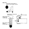
- FIG. 22 illustrates a groove shape formed when ellipse cutting edges are used as illustrating a variation aspect of the cutting edge shape projected on the work section corresponding to a cutting edge position in the groove depth direction.
- the shapes of the inner wall and outer wall of the groove are determined by combination of variation of a projected view of the cutting edge on the work section and the trajectory of the center portion of the cutting edge.
- FIG. 23 illustrates a shape of a groove which is formed when rectangular cutting edges are similarly used.
- the groove width can be lessened compared to a machined groove utilizing circular cutting edges (i.e., circular chips). Then, when the ellipse cutting edge is attached as the major axis direction thereof being rotated by a certain angle against the rotating shaft of the tool, the bank amount can be reduced.
- an optimal shape of a cutting edge is selected corresponding to a diameter, depth and width of a groove being a machining target, a diameter of an distal end of a spreading portion, and the like, optimal machining can be actualized.
- setting can be arbitrarily performed in the case that deviation ⁇ occurring in the direction of an axis oriented toward a work center axis in parallel to a work face from an original point which is a point on the work face on which the deepest point of cutting is projected or in the direction of an projected axis of a tool rotating shaft on the work face is reduced by inclining the rotating shaft of a cutting tool against a work end, and the like. Accordingly, efficiency improvement of cutting machining and lifetime elongation of the tool can be achieved while enhancing machining accuracy of a groove even when being adopted to groove machining of normal workpiece material as well as difficult-to-cut material. Hence, it is possible to be widely adopted to a variety of cutting machining apparatuses.
Landscapes
- Engineering & Computer Science (AREA)
- Mechanical Engineering (AREA)
- Milling Processes (AREA)
Applications Claiming Priority (1)
| Application Number | Priority Date | Filing Date | Title |
|---|---|---|---|
| PCT/JP2010/056935 WO2011132252A1 (ja) | 2010-04-19 | 2010-04-19 | 切削加工方法及び切削加工装置 |
Publications (3)
| Publication Number | Publication Date |
|---|---|
| EP2476497A1 true EP2476497A1 (de) | 2012-07-18 |
| EP2476497A4 EP2476497A4 (de) | 2014-04-02 |
| EP2476497B1 EP2476497B1 (de) | 2015-05-13 |
Family
ID=44461722
Family Applications (1)
| Application Number | Title | Priority Date | Filing Date |
|---|---|---|---|
| EP20100850197 Not-in-force EP2476497B1 (de) | 2010-04-19 | 2010-04-19 | Schneideverfahren und schneidevorrichtung |
Country Status (5)
| Country | Link |
|---|---|
| US (1) | US8690498B2 (de) |
| EP (1) | EP2476497B1 (de) |
| JP (1) | JP4732549B1 (de) |
| CN (1) | CN102574221B (de) |
| WO (1) | WO2011132252A1 (de) |
Families Citing this family (13)
| Publication number | Priority date | Publication date | Assignee | Title |
|---|---|---|---|---|
| US9956624B2 (en) * | 2013-04-30 | 2018-05-01 | Citizen Watch Co., Ltd. | Chamfer machining method |
| CN106239256A (zh) * | 2015-05-20 | 2016-12-21 | 刘千于 | 阀片制造方式 |
| CN106660143B (zh) * | 2015-07-24 | 2018-04-06 | 山崎马扎克公司 | 沟部的加工方法 |
| WO2017199911A1 (ja) * | 2016-05-19 | 2017-11-23 | 兼房株式会社 | 回転切削工具を用いたディンプル加工方法 |
| CN108406440B (zh) * | 2018-02-07 | 2019-08-06 | 东方电气集团东方锅炉股份有限公司 | 旋转工作台上圆弧段类工件表面待加工点位坐标获取方法 |
| JP6777692B2 (ja) * | 2018-08-10 | 2020-10-28 | ファナック株式会社 | 加工経路生成装置及び数値制御装置 |
| CN113423527B (zh) * | 2019-02-13 | 2025-05-13 | 日东电工株式会社 | 光学薄膜的制造方法 |
| CN111438443B (zh) * | 2019-11-05 | 2022-03-22 | 南京工业大学 | 一种通过激光多次扫描烧蚀在工件表面加工可控微沟槽的方法 |
| CN112754591B (zh) * | 2020-09-27 | 2024-11-26 | 清华大学 | 凹槽加工装置及其使用方法 |
| KR102440865B1 (ko) * | 2020-10-16 | 2022-09-06 | 하나아이티엠(주) | 터빈세그먼트의 세그먼트그루브 연마가공장치 |
| CN115562162B (zh) * | 2022-10-21 | 2026-04-10 | 成都锦江电子系统工程有限公司 | 用于加工波导裂缝的自动测量方法及批量补偿加工方法 |
| CN116571795B (zh) * | 2023-04-18 | 2026-03-03 | 大连橡胶塑料机械有限公司 | 一种冷硬铸铁辊筒工作辊面v型沟槽高效加工方法 |
| CN118927015B (zh) * | 2024-05-29 | 2025-11-18 | 南昌大学 | 一种基于圆槽定位的超精密飞切精对刀方法 |
Family Cites Families (20)
| Publication number | Priority date | Publication date | Assignee | Title |
|---|---|---|---|---|
| GB1365439A (en) * | 1972-01-07 | 1974-09-04 | Gen Motors Corp | Method of milling curved grooves |
| US3839942A (en) | 1972-01-07 | 1974-10-08 | Gen Motors Corp | Method for simultaneously milling grooves in opposite sides of a workpiece |
| GB1451129A (en) * | 1973-06-27 | 1976-09-29 | Gen Motors Corp | Milling cutters |
| US4517769A (en) * | 1981-05-20 | 1985-05-21 | Tokyo Shibaura Denki Kabushiki Kaisha | Method and apparatus for forming oblique groove in semiconductor device |
| JPS6268216A (ja) * | 1985-09-19 | 1987-03-28 | Hitachi Ltd | 工作物の円弧溝加工方法 |
| JPH11300505A (ja) | 1998-04-20 | 1999-11-02 | Yamazaki Mazak Corp | サイドカッタ |
| JP3884884B2 (ja) * | 1999-06-22 | 2007-02-21 | 東芝機械株式会社 | インコーナ切削加工方法および切削工具 |
| JP3652182B2 (ja) * | 1999-09-24 | 2005-05-25 | キヤノン株式会社 | 回折格子の加工方法及び加工装置 |
| JP3757807B2 (ja) | 2001-03-12 | 2006-03-22 | 日産自動車株式会社 | 旋削加工方法と旋削加工用工具 |
| JP2003117716A (ja) * | 2001-08-09 | 2003-04-23 | Nissan Motor Co Ltd | 加工装置および加工方法 |
| JP2004062355A (ja) * | 2002-07-26 | 2004-02-26 | Roland Dg Corp | 溝形状の切削方法、プログラムおよび記憶媒体 |
| EP1614495B1 (de) * | 2003-04-09 | 2017-08-30 | Mitsubishi Denki Kabushiki Kaisha | Vorrichtung zur bearbeitung eines schraubenrotors |
| DE10352542A1 (de) * | 2003-11-11 | 2005-06-09 | Mtu Aero Engines Gmbh | Fräswerkzeug und Verfahren zum Fräsen von Vertiefungen |
| US20100035524A1 (en) * | 2005-06-06 | 2010-02-11 | Nidec Sankyo Corporation | Method of producing optical element, and optical element |
| JP4989950B2 (ja) * | 2005-11-01 | 2012-08-01 | 本田技研工業株式会社 | ワークの加工方法 |
| CN100453282C (zh) * | 2006-11-23 | 2009-01-21 | 成都天鑫塑料机械有限公司 | 塑料检查井承插式支管承口开槽方法 |
| US7303461B1 (en) * | 2006-12-05 | 2007-12-04 | Pratt & Whitney Canada Corp. | Method of machining airfoils by disc tools |
| CN201008975Y (zh) * | 2007-03-15 | 2008-01-23 | 杭州电子科技大学 | 双刀反向进给超声波扭转振动车铣系统 |
| CN201008976Y (zh) * | 2007-03-15 | 2008-01-23 | 杭州电子科技大学 | 超声波扭转振动车铣系统 |
| US20130000121A1 (en) * | 2011-06-30 | 2013-01-03 | Gregory Mark Burgess | Spherical cutter and method for machining a curved slot |
-
2010
- 2010-04-19 WO PCT/JP2010/056935 patent/WO2011132252A1/ja not_active Ceased
- 2010-04-19 JP JP2010529182A patent/JP4732549B1/ja active Active
- 2010-04-19 CN CN2010800418262A patent/CN102574221B/zh not_active Expired - Fee Related
- 2010-04-19 US US13/497,599 patent/US8690498B2/en not_active Expired - Fee Related
- 2010-04-19 EP EP20100850197 patent/EP2476497B1/de not_active Not-in-force
Also Published As
| Publication number | Publication date |
|---|---|
| JPWO2011132252A1 (ja) | 2013-07-18 |
| CN102574221A (zh) | 2012-07-11 |
| WO2011132252A1 (ja) | 2011-10-27 |
| US8690498B2 (en) | 2014-04-08 |
| EP2476497A4 (de) | 2014-04-02 |
| JP4732549B1 (ja) | 2011-07-27 |
| CN102574221B (zh) | 2013-12-11 |
| EP2476497B1 (de) | 2015-05-13 |
| US20120230792A1 (en) | 2012-09-13 |
Similar Documents
| Publication | Publication Date | Title |
|---|---|---|
| EP2476497B1 (de) | Schneideverfahren und schneidevorrichtung | |
| EP2070619B1 (de) | Verfahren zur maschinellen Bearbeitung einer Turbinenscheibe | |
| CA2805935C (en) | Elbow formed by cutting and method for manufacturing same | |
| EP1407852B1 (de) | Verfahren zum Bearbeiten von axialen Nuten für Schaufeln in Turbinenscheiben für Strahltriebwerke | |
| US8874255B2 (en) | Method of control of rotation of spindle and control system of machine tool | |
| US8286348B2 (en) | Method of manufacturing and refinishing integrally bladed rotors | |
| KR20110103066A (ko) | 자동차 항공부품 정밀공차홀 가공용 드릴 리머공구 | |
| CN114258454B (zh) | 整合旋翼的制造方法、存储介质和整合旋翼 | |
| Khusainov et al. | Selecting optimal cutting tools for lathes. | |
| CN114192811B (zh) | 车铣复合机床自动车削加工钛合金产品的方法 | |
| CN110977062B (zh) | 一种大直径螺纹单次走刀快速车削加工刀具及方法 | |
| Matsumura et al. | Simulation of drilling process for control of burr formation | |
| Zaleski et al. | Highly efficient milling on the example of selected machining strategies | |
| CN106334840B (zh) | 齿轮加工装置 | |
| CN112518424B (zh) | 螺纹车削的切削力预测方法和装置 | |
| KR20230059855A (ko) | 다공성 구조의 내부 냉각 유로 가지는 절삭공구 | |
| RU2615387C2 (ru) | Способ фрезерования поверхностей заготовок и обрабатывающий центр для его осуществления | |
| JP2009184036A (ja) | 切削工具 | |
| CN205684781U (zh) | 一种刀具 | |
| JP6626853B2 (ja) | 回転切削工具 | |
| Selvaraj et al. | Multi-tasking machines: a new approach to increase the productivity of aircraft components manufacture | |
| US7337523B1 (en) | Methods and apparatus for an annular core cutter | |
| EP2897749B1 (de) | Fräser und verfahren zur verwendung | |
| RU2138370C1 (ru) | Способ вытяжного растачивания внутреннего отверстия заготовки под прокат из циркония и сплавов на его основе и инструмент для осуществления способа | |
| RU2247007C2 (ru) | Режущий инструмент |
Legal Events
| Date | Code | Title | Description |
|---|---|---|---|
| PUAI | Public reference made under article 153(3) epc to a published international application that has entered the european phase |
Free format text: ORIGINAL CODE: 0009012 |
|
| 17P | Request for examination filed |
Effective date: 20120310 |
|
| AK | Designated contracting states |
Kind code of ref document: A1 Designated state(s): AT BE BG CH CY CZ DE DK EE ES FI FR GB GR HR HU IE IS IT LI LT LU LV MC MK MT NL NO PL PT RO SE SI SK SM TR |
|
| DAX | Request for extension of the european patent (deleted) | ||
| A4 | Supplementary search report drawn up and despatched |
Effective date: 20140228 |
|
| RIC1 | Information provided on ipc code assigned before grant |
Ipc: B23C 3/28 20060101AFI20140224BHEP Ipc: B23C 5/02 20060101ALI20140224BHEP Ipc: B23C 5/12 20060101ALI20140224BHEP Ipc: B23Q 15/22 20060101ALI20140224BHEP |
|
| RIC1 | Information provided on ipc code assigned before grant |
Ipc: B23C 5/12 20060101ALI20141219BHEP Ipc: B23C 3/34 20060101ALI20141219BHEP Ipc: B23C 5/02 20060101ALI20141219BHEP Ipc: B23C 3/28 20060101AFI20141219BHEP Ipc: B23Q 15/22 20060101ALI20141219BHEP |
|
| GRAP | Despatch of communication of intention to grant a patent |
Free format text: ORIGINAL CODE: EPIDOSNIGR1 |
|
| INTG | Intention to grant announced |
Effective date: 20150129 |
|
| GRAS | Grant fee paid |
Free format text: ORIGINAL CODE: EPIDOSNIGR3 |
|
| GRAA | (expected) grant |
Free format text: ORIGINAL CODE: 0009210 |
|
| AK | Designated contracting states |
Kind code of ref document: B1 Designated state(s): AT BE BG CH CY CZ DE DK EE ES FI FR GB GR HR HU IE IS IT LI LT LU LV MC MK MT NL NO PL PT RO SE SI SK SM TR |
|
| REG | Reference to a national code |
Ref country code: GB Ref legal event code: FG4D |
|
| REG | Reference to a national code |
Ref country code: CH Ref legal event code: EP |
|
| REG | Reference to a national code |
Ref country code: IE Ref legal event code: FG4D |
|
| REG | Reference to a national code |
Ref country code: AT Ref legal event code: REF Ref document number: 726635 Country of ref document: AT Kind code of ref document: T Effective date: 20150615 |
|
| REG | Reference to a national code |
Ref country code: DE Ref legal event code: R096 Ref document number: 602010024689 Country of ref document: DE Effective date: 20150625 |
|
| REG | Reference to a national code |
Ref country code: AT Ref legal event code: MK05 Ref document number: 726635 Country of ref document: AT Kind code of ref document: T Effective date: 20150513 |
|
| REG | Reference to a national code |
Ref country code: NL Ref legal event code: MP Effective date: 20150513 |
|
| REG | Reference to a national code |
Ref country code: LT Ref legal event code: MG4D |
|
| PG25 | Lapsed in a contracting state [announced via postgrant information from national office to epo] |
Ref country code: NO Free format text: LAPSE BECAUSE OF FAILURE TO SUBMIT A TRANSLATION OF THE DESCRIPTION OR TO PAY THE FEE WITHIN THE PRESCRIBED TIME-LIMIT Effective date: 20150813 Ref country code: ES Free format text: LAPSE BECAUSE OF FAILURE TO SUBMIT A TRANSLATION OF THE DESCRIPTION OR TO PAY THE FEE WITHIN THE PRESCRIBED TIME-LIMIT Effective date: 20150513 Ref country code: PT Free format text: LAPSE BECAUSE OF FAILURE TO SUBMIT A TRANSLATION OF THE DESCRIPTION OR TO PAY THE FEE WITHIN THE PRESCRIBED TIME-LIMIT Effective date: 20150914 Ref country code: HR Free format text: LAPSE BECAUSE OF FAILURE TO SUBMIT A TRANSLATION OF THE DESCRIPTION OR TO PAY THE FEE WITHIN THE PRESCRIBED TIME-LIMIT Effective date: 20150513 Ref country code: LT Free format text: LAPSE BECAUSE OF FAILURE TO SUBMIT A TRANSLATION OF THE DESCRIPTION OR TO PAY THE FEE WITHIN THE PRESCRIBED TIME-LIMIT Effective date: 20150513 Ref country code: FI Free format text: LAPSE BECAUSE OF FAILURE TO SUBMIT A TRANSLATION OF THE DESCRIPTION OR TO PAY THE FEE WITHIN THE PRESCRIBED TIME-LIMIT Effective date: 20150513 |
|
| PG25 | Lapsed in a contracting state [announced via postgrant information from national office to epo] |
Ref country code: AT Free format text: LAPSE BECAUSE OF FAILURE TO SUBMIT A TRANSLATION OF THE DESCRIPTION OR TO PAY THE FEE WITHIN THE PRESCRIBED TIME-LIMIT Effective date: 20150513 Ref country code: BG Free format text: LAPSE BECAUSE OF FAILURE TO SUBMIT A TRANSLATION OF THE DESCRIPTION OR TO PAY THE FEE WITHIN THE PRESCRIBED TIME-LIMIT Effective date: 20150813 Ref country code: IS Free format text: LAPSE BECAUSE OF FAILURE TO SUBMIT A TRANSLATION OF THE DESCRIPTION OR TO PAY THE FEE WITHIN THE PRESCRIBED TIME-LIMIT Effective date: 20150913 Ref country code: LV Free format text: LAPSE BECAUSE OF FAILURE TO SUBMIT A TRANSLATION OF THE DESCRIPTION OR TO PAY THE FEE WITHIN THE PRESCRIBED TIME-LIMIT Effective date: 20150513 Ref country code: GR Free format text: LAPSE BECAUSE OF FAILURE TO SUBMIT A TRANSLATION OF THE DESCRIPTION OR TO PAY THE FEE WITHIN THE PRESCRIBED TIME-LIMIT Effective date: 20150814 |
|
| PG25 | Lapsed in a contracting state [announced via postgrant information from national office to epo] |
Ref country code: DK Free format text: LAPSE BECAUSE OF FAILURE TO SUBMIT A TRANSLATION OF THE DESCRIPTION OR TO PAY THE FEE WITHIN THE PRESCRIBED TIME-LIMIT Effective date: 20150513 Ref country code: EE Free format text: LAPSE BECAUSE OF FAILURE TO SUBMIT A TRANSLATION OF THE DESCRIPTION OR TO PAY THE FEE WITHIN THE PRESCRIBED TIME-LIMIT Effective date: 20150513 |
|
| REG | Reference to a national code |
Ref country code: DE Ref legal event code: R097 Ref document number: 602010024689 Country of ref document: DE |
|
| PG25 | Lapsed in a contracting state [announced via postgrant information from national office to epo] |
Ref country code: RO Free format text: LAPSE BECAUSE OF NON-PAYMENT OF DUE FEES Effective date: 20150513 Ref country code: SK Free format text: LAPSE BECAUSE OF FAILURE TO SUBMIT A TRANSLATION OF THE DESCRIPTION OR TO PAY THE FEE WITHIN THE PRESCRIBED TIME-LIMIT Effective date: 20150513 Ref country code: CZ Free format text: LAPSE BECAUSE OF FAILURE TO SUBMIT A TRANSLATION OF THE DESCRIPTION OR TO PAY THE FEE WITHIN THE PRESCRIBED TIME-LIMIT Effective date: 20150513 Ref country code: PL Free format text: LAPSE BECAUSE OF FAILURE TO SUBMIT A TRANSLATION OF THE DESCRIPTION OR TO PAY THE FEE WITHIN THE PRESCRIBED TIME-LIMIT Effective date: 20150513 |
|
| REG | Reference to a national code |
Ref country code: FR Ref legal event code: PLFP Year of fee payment: 7 |
|
| PLBE | No opposition filed within time limit |
Free format text: ORIGINAL CODE: 0009261 |
|
| STAA | Information on the status of an ep patent application or granted ep patent |
Free format text: STATUS: NO OPPOSITION FILED WITHIN TIME LIMIT |
|
| 26N | No opposition filed |
Effective date: 20160216 |
|
| PG25 | Lapsed in a contracting state [announced via postgrant information from national office to epo] |
Ref country code: SI Free format text: LAPSE BECAUSE OF FAILURE TO SUBMIT A TRANSLATION OF THE DESCRIPTION OR TO PAY THE FEE WITHIN THE PRESCRIBED TIME-LIMIT Effective date: 20150513 |
|
| PG25 | Lapsed in a contracting state [announced via postgrant information from national office to epo] |
Ref country code: BE Free format text: LAPSE BECAUSE OF FAILURE TO SUBMIT A TRANSLATION OF THE DESCRIPTION OR TO PAY THE FEE WITHIN THE PRESCRIBED TIME-LIMIT Effective date: 20150513 |
|
| REG | Reference to a national code |
Ref country code: CH Ref legal event code: PL |
|
| PG25 | Lapsed in a contracting state [announced via postgrant information from national office to epo] |
Ref country code: LU Free format text: LAPSE BECAUSE OF FAILURE TO SUBMIT A TRANSLATION OF THE DESCRIPTION OR TO PAY THE FEE WITHIN THE PRESCRIBED TIME-LIMIT Effective date: 20160419 |
|
| REG | Reference to a national code |
Ref country code: IE Ref legal event code: MM4A |
|
| PG25 | Lapsed in a contracting state [announced via postgrant information from national office to epo] |
Ref country code: CH Free format text: LAPSE BECAUSE OF NON-PAYMENT OF DUE FEES Effective date: 20160430 Ref country code: LI Free format text: LAPSE BECAUSE OF NON-PAYMENT OF DUE FEES Effective date: 20160430 |
|
| REG | Reference to a national code |
Ref country code: FR Ref legal event code: PLFP Year of fee payment: 8 |
|
| PG25 | Lapsed in a contracting state [announced via postgrant information from national office to epo] |
Ref country code: IE Free format text: LAPSE BECAUSE OF NON-PAYMENT OF DUE FEES Effective date: 20160419 |
|
| PG25 | Lapsed in a contracting state [announced via postgrant information from national office to epo] |
Ref country code: SE Free format text: LAPSE BECAUSE OF FAILURE TO SUBMIT A TRANSLATION OF THE DESCRIPTION OR TO PAY THE FEE WITHIN THE PRESCRIBED TIME-LIMIT Effective date: 20150513 Ref country code: NL Free format text: LAPSE BECAUSE OF FAILURE TO SUBMIT A TRANSLATION OF THE DESCRIPTION OR TO PAY THE FEE WITHIN THE PRESCRIBED TIME-LIMIT Effective date: 20150513 |
|
| REG | Reference to a national code |
Ref country code: FR Ref legal event code: PLFP Year of fee payment: 9 |
|
| PG25 | Lapsed in a contracting state [announced via postgrant information from national office to epo] |
Ref country code: CY Free format text: LAPSE BECAUSE OF FAILURE TO SUBMIT A TRANSLATION OF THE DESCRIPTION OR TO PAY THE FEE WITHIN THE PRESCRIBED TIME-LIMIT Effective date: 20150513 Ref country code: SM Free format text: LAPSE BECAUSE OF FAILURE TO SUBMIT A TRANSLATION OF THE DESCRIPTION OR TO PAY THE FEE WITHIN THE PRESCRIBED TIME-LIMIT Effective date: 20150513 Ref country code: HU Free format text: LAPSE BECAUSE OF FAILURE TO SUBMIT A TRANSLATION OF THE DESCRIPTION OR TO PAY THE FEE WITHIN THE PRESCRIBED TIME-LIMIT; INVALID AB INITIO Effective date: 20100419 |
|
| PG25 | Lapsed in a contracting state [announced via postgrant information from national office to epo] |
Ref country code: MT Free format text: LAPSE BECAUSE OF NON-PAYMENT OF DUE FEES Effective date: 20160430 Ref country code: MC Free format text: LAPSE BECAUSE OF FAILURE TO SUBMIT A TRANSLATION OF THE DESCRIPTION OR TO PAY THE FEE WITHIN THE PRESCRIBED TIME-LIMIT Effective date: 20150513 Ref country code: TR Free format text: LAPSE BECAUSE OF FAILURE TO SUBMIT A TRANSLATION OF THE DESCRIPTION OR TO PAY THE FEE WITHIN THE PRESCRIBED TIME-LIMIT Effective date: 20150513 Ref country code: MK Free format text: LAPSE BECAUSE OF FAILURE TO SUBMIT A TRANSLATION OF THE DESCRIPTION OR TO PAY THE FEE WITHIN THE PRESCRIBED TIME-LIMIT Effective date: 20150513 |
|
| PGFP | Annual fee paid to national office [announced via postgrant information from national office to epo] |
Ref country code: FR Payment date: 20190313 Year of fee payment: 10 |
|
| PGFP | Annual fee paid to national office [announced via postgrant information from national office to epo] |
Ref country code: IT Payment date: 20190419 Year of fee payment: 10 Ref country code: DE Payment date: 20190410 Year of fee payment: 10 |
|
| PGFP | Annual fee paid to national office [announced via postgrant information from national office to epo] |
Ref country code: GB Payment date: 20190417 Year of fee payment: 10 |
|
| REG | Reference to a national code |
Ref country code: DE Ref legal event code: R119 Ref document number: 602010024689 Country of ref document: DE |
|
| PG25 | Lapsed in a contracting state [announced via postgrant information from national office to epo] |
Ref country code: DE Free format text: LAPSE BECAUSE OF NON-PAYMENT OF DUE FEES Effective date: 20201103 Ref country code: FR Free format text: LAPSE BECAUSE OF NON-PAYMENT OF DUE FEES Effective date: 20200430 |
|
| GBPC | Gb: european patent ceased through non-payment of renewal fee |
Effective date: 20200419 |
|
| PG25 | Lapsed in a contracting state [announced via postgrant information from national office to epo] |
Ref country code: GB Free format text: LAPSE BECAUSE OF NON-PAYMENT OF DUE FEES Effective date: 20200419 |
|
| PG25 | Lapsed in a contracting state [announced via postgrant information from national office to epo] |
Ref country code: IT Free format text: LAPSE BECAUSE OF NON-PAYMENT OF DUE FEES Effective date: 20200419 |