EP2476505A1 - Laser processing method and laser processing device - Google Patents
Laser processing method and laser processing device Download PDFInfo
- Publication number
- EP2476505A1 EP2476505A1 EP10815397A EP10815397A EP2476505A1 EP 2476505 A1 EP2476505 A1 EP 2476505A1 EP 10815397 A EP10815397 A EP 10815397A EP 10815397 A EP10815397 A EP 10815397A EP 2476505 A1 EP2476505 A1 EP 2476505A1
- Authority
- EP
- European Patent Office
- Prior art keywords
- focused
- cross
- cut
- condenser lens
- depth
- Prior art date
- Legal status (The legal status is an assumption and is not a legal conclusion. Google has not performed a legal analysis and makes no representation as to the accuracy of the status listed.)
- Granted
Links
Images











Classifications
-
- B—PERFORMING OPERATIONS; TRANSPORTING
- B23—MACHINE TOOLS; METAL-WORKING NOT OTHERWISE PROVIDED FOR
- B23K—SOLDERING OR UNSOLDERING; WELDING; CLADDING OR PLATING BY SOLDERING OR WELDING; CUTTING BY APPLYING HEAT LOCALLY, e.g. FLAME CUTTING; WORKING BY LASER BEAM
- B23K26/00—Working by laser beam, e.g. welding, cutting or boring
- B23K26/36—Removing material
- B23K26/38—Removing material by boring or cutting
-
- B—PERFORMING OPERATIONS; TRANSPORTING
- B28—WORKING CEMENT, CLAY, OR STONE
- B28D—WORKING STONE OR STONE-LIKE MATERIALS
- B28D5/00—Fine working of gems, jewels, crystals, e.g. of semiconductor material; apparatus or devices therefor
-
- B—PERFORMING OPERATIONS; TRANSPORTING
- B23—MACHINE TOOLS; METAL-WORKING NOT OTHERWISE PROVIDED FOR
- B23K—SOLDERING OR UNSOLDERING; WELDING; CLADDING OR PLATING BY SOLDERING OR WELDING; CUTTING BY APPLYING HEAT LOCALLY, e.g. FLAME CUTTING; WORKING BY LASER BEAM
- B23K26/00—Working by laser beam, e.g. welding, cutting or boring
- B23K26/02—Positioning or observing the workpiece, e.g. with respect to the point of impact; Aligning, aiming or focusing the laser beam
- B23K26/04—Automatically aligning, aiming or focusing the laser beam, e.g. using the back-scattered light
-
- B—PERFORMING OPERATIONS; TRANSPORTING
- B23—MACHINE TOOLS; METAL-WORKING NOT OTHERWISE PROVIDED FOR
- B23K—SOLDERING OR UNSOLDERING; WELDING; CLADDING OR PLATING BY SOLDERING OR WELDING; CUTTING BY APPLYING HEAT LOCALLY, e.g. FLAME CUTTING; WORKING BY LASER BEAM
- B23K26/00—Working by laser beam, e.g. welding, cutting or boring
- B23K26/02—Positioning or observing the workpiece, e.g. with respect to the point of impact; Aligning, aiming or focusing the laser beam
- B23K26/06—Shaping the laser beam, e.g. by masks or multi-focusing
- B23K26/0604—Shaping the laser beam, e.g. by masks or multi-focusing by a combination of beams
- B23K26/0608—Shaping the laser beam, e.g. by masks or multi-focusing by a combination of beams in the same heat affected zone [HAZ]
-
- B—PERFORMING OPERATIONS; TRANSPORTING
- B23—MACHINE TOOLS; METAL-WORKING NOT OTHERWISE PROVIDED FOR
- B23K—SOLDERING OR UNSOLDERING; WELDING; CLADDING OR PLATING BY SOLDERING OR WELDING; CUTTING BY APPLYING HEAT LOCALLY, e.g. FLAME CUTTING; WORKING BY LASER BEAM
- B23K26/00—Working by laser beam, e.g. welding, cutting or boring
- B23K26/02—Positioning or observing the workpiece, e.g. with respect to the point of impact; Aligning, aiming or focusing the laser beam
- B23K26/06—Shaping the laser beam, e.g. by masks or multi-focusing
- B23K26/0604—Shaping the laser beam, e.g. by masks or multi-focusing by a combination of beams
- B23K26/0613—Shaping the laser beam, e.g. by masks or multi-focusing by a combination of beams having a common axis
- B23K26/0617—Shaping the laser beam, e.g. by masks or multi-focusing by a combination of beams having a common axis and with spots spaced along the common axis
-
- B—PERFORMING OPERATIONS; TRANSPORTING
- B23—MACHINE TOOLS; METAL-WORKING NOT OTHERWISE PROVIDED FOR
- B23K—SOLDERING OR UNSOLDERING; WELDING; CLADDING OR PLATING BY SOLDERING OR WELDING; CUTTING BY APPLYING HEAT LOCALLY, e.g. FLAME CUTTING; WORKING BY LASER BEAM
- B23K26/00—Working by laser beam, e.g. welding, cutting or boring
- B23K26/02—Positioning or observing the workpiece, e.g. with respect to the point of impact; Aligning, aiming or focusing the laser beam
- B23K26/06—Shaping the laser beam, e.g. by masks or multi-focusing
- B23K26/064—Shaping the laser beam, e.g. by masks or multi-focusing by means of optical elements, e.g. lenses, mirrors or prisms
- B23K26/0648—Shaping the laser beam, e.g. by masks or multi-focusing by means of optical elements, e.g. lenses, mirrors or prisms comprising lenses
-
- B—PERFORMING OPERATIONS; TRANSPORTING
- B23—MACHINE TOOLS; METAL-WORKING NOT OTHERWISE PROVIDED FOR
- B23K—SOLDERING OR UNSOLDERING; WELDING; CLADDING OR PLATING BY SOLDERING OR WELDING; CUTTING BY APPLYING HEAT LOCALLY, e.g. FLAME CUTTING; WORKING BY LASER BEAM
- B23K26/00—Working by laser beam, e.g. welding, cutting or boring
- B23K26/02—Positioning or observing the workpiece, e.g. with respect to the point of impact; Aligning, aiming or focusing the laser beam
- B23K26/06—Shaping the laser beam, e.g. by masks or multi-focusing
- B23K26/064—Shaping the laser beam, e.g. by masks or multi-focusing by means of optical elements, e.g. lenses, mirrors or prisms
- B23K26/0652—Shaping the laser beam, e.g. by masks or multi-focusing by means of optical elements, e.g. lenses, mirrors or prisms comprising prisms
-
- B—PERFORMING OPERATIONS; TRANSPORTING
- B23—MACHINE TOOLS; METAL-WORKING NOT OTHERWISE PROVIDED FOR
- B23K—SOLDERING OR UNSOLDERING; WELDING; CLADDING OR PLATING BY SOLDERING OR WELDING; CUTTING BY APPLYING HEAT LOCALLY, e.g. FLAME CUTTING; WORKING BY LASER BEAM
- B23K26/00—Working by laser beam, e.g. welding, cutting or boring
- B23K26/02—Positioning or observing the workpiece, e.g. with respect to the point of impact; Aligning, aiming or focusing the laser beam
- B23K26/06—Shaping the laser beam, e.g. by masks or multi-focusing
- B23K26/067—Dividing the beam into multiple beams, e.g. multi-focusing
- B23K26/0676—Dividing the beam into multiple beams, e.g. multi-focusing into dependently operating sub-beams, e.g. an array of spots with fixed spatial relationship or for performing simultaneously identical operations
-
- B—PERFORMING OPERATIONS; TRANSPORTING
- B23—MACHINE TOOLS; METAL-WORKING NOT OTHERWISE PROVIDED FOR
- B23K—SOLDERING OR UNSOLDERING; WELDING; CLADDING OR PLATING BY SOLDERING OR WELDING; CUTTING BY APPLYING HEAT LOCALLY, e.g. FLAME CUTTING; WORKING BY LASER BEAM
- B23K26/00—Working by laser beam, e.g. welding, cutting or boring
- B23K26/36—Removing material
- B23K26/40—Removing material taking account of the properties of the material involved
-
- B—PERFORMING OPERATIONS; TRANSPORTING
- B23—MACHINE TOOLS; METAL-WORKING NOT OTHERWISE PROVIDED FOR
- B23K—SOLDERING OR UNSOLDERING; WELDING; CLADDING OR PLATING BY SOLDERING OR WELDING; CUTTING BY APPLYING HEAT LOCALLY, e.g. FLAME CUTTING; WORKING BY LASER BEAM
- B23K26/00—Working by laser beam, e.g. welding, cutting or boring
- B23K26/50—Working by transmitting the laser beam through or within the workpiece
- B23K26/53—Working by transmitting the laser beam through or within the workpiece for modifying or reforming the material inside the workpiece, e.g. for producing break initiation cracks
-
- C—CHEMISTRY; METALLURGY
- C03—GLASS; MINERAL OR SLAG WOOL
- C03B—MANUFACTURE, SHAPING, OR SUPPLEMENTARY PROCESSES
- C03B33/00—Severing cooled glass
- C03B33/09—Severing cooled glass by thermal shock
- C03B33/091—Severing cooled glass by thermal shock using at least one focussed radiation beam, e.g. laser beam
- C03B33/093—Severing cooled glass by thermal shock using at least one focussed radiation beam, e.g. laser beam using two or more focussed radiation beams
-
- B—PERFORMING OPERATIONS; TRANSPORTING
- B23—MACHINE TOOLS; METAL-WORKING NOT OTHERWISE PROVIDED FOR
- B23K—SOLDERING OR UNSOLDERING; WELDING; CLADDING OR PLATING BY SOLDERING OR WELDING; CUTTING BY APPLYING HEAT LOCALLY, e.g. FLAME CUTTING; WORKING BY LASER BEAM
- B23K2103/00—Materials to be soldered, welded or cut
- B23K2103/50—Inorganic materials other than metals or composite materials
Definitions
- the present invention relates to a laser processing method and a laser processing device for forming a modification region serving as a starting point of cutting, inside a member to be cut, by irradiating the member to be cut with focused laser light along a planned cutting line on the member to be cut.
- a short-pulse laser having a wavelength transparent to the plate is focused and irradiated to the inside of a plate to be cut along a planned cutting line, to thereby generate a fine molten trace (modification region), inside which micro cracks grow gregariously, and then a stress is applied and the plate is divided by utilizing cracks caused toward the direction of the plate thickness from the fine molten trace as a starting point (for example, see Patent Document 1).
- a processing method in which one pulse laser beam is divided into three and a time difference is given between them (the second beam is delayed from the first beam and the third beam is delayed from the second beam) and then positions shifted from one another are irradiated with the three focused laser beams (for example, see Patent Document 2).
- the laser beam is focused in a circular spot, and thus an inside stress that causes cracks to be generated and grow works isotropically. Because of this, cracks are generated and grow in directions other than the direction along the planned cutting line, and it is not possible to centralize the generation and growth of cracks in the direction of the planned cutting line. As a result, the flatness of the divided section is impaired. Furthermore, there is also a problem in which when a circular spot is irradiated along the planned cutting line, the number of irradiation spots per unit length increases, and thus the processing speed is slow. Moreover, when the plate to be cut is thick, it is necessary to repeat processing while shifting the focus position in the thickness direction, but the amount by which the position is shifted in the thickness direction has to be reduced, and thus the processing speed is further lowered.
- the processing speed in the direction of the planned cutting line (relative movement speed of the optical axis of the condenser lens) can be increased by connecting and forming the three spots in the direction of the planned cutting line. Furthermore, by connecting and forming the three spots in the thickness direction, it is expected that the amount by which the focus position is shifted in the thickness direction can be increased, and the processing speed in the thickness direction (relative movement speed in the thickness direction of the condenser lens) can be increased.
- the subsequent pulse beams are affected by the heat generated by the pulse beam with which previous irradiation was performed.
- the brittle material that is the member to be cut is heated to temperatures at which amorphous transition occurs, the material changes into a ductile material, and thus even if the brittle material is irradiated with the subsequent pulse beams in the vicinity of the region heated by the previous pulse beam, it becomes harder for the stress caused by a temperature difference to be generated and at the same time, it becomes harder for cracks to grow because of the influence of the change in the physical properties of the material (for example, dissolution). As a result, the processing speed is not increased as expected.
- the refractive index and absorption coefficient of the brittle material that is the member to be cut, for a laser beam also change depending on temperature, and thus, even if the brittle material is irradiated with the subsequent pulse beams in the vicinity of the region heated by the previous pulse beam, the laser beam is absorbed before reaching a focal point and there is also a problem in which a sufficient amount of energy does not reach the focal point or in which the position of the focal point shifts. If the position of the focal point shifts, the three spots cannot be connected in the thickness direction and it is not possible to increase the amount by which the focus position is shifted in the thickness direction. As a result, the processing speed in the thickness direction (relative movement speed in the thickness direction of the condenser lens) is reduced.
- the present invention has been made in view of the above-mentioned problems and an object thereof is to provide a laser processing method and a laser processing device having a high processing speed and high energy efficiency.
- a laser processing method of the present invention made in order to solve the above-mentioned problems is a laser processing method for forming a modification region serving as a starting point of cutting inside a member to be cut along a planned cutting line by relatively moving an optical axis of a condenser lens along the planned cutting line of the member to be cut and by irradiating the member to be cut with focused laser light, wherein a plurality of cross-sectional focused spots is simultaneously formed at positions on a cross section which is perpendicular to the optical axis of the condenser lens at positions having a predetermined depth from a surface of the member to be cut and which is parallel to the surface and, at that time, at least one cross-sectional focused spot of the plurality of cross-sectional focused spots is formed on a projection line of the planned cutting line onto the cross section to form one or more inside modification regions having a desired shape.
- another laser processing method of the present invention made in order to solve the above-mentioned problems is a laser processing method for forming a modification region serving as a starting point of cutting inside a member to be cut along a planned cutting line by relatively moving an optical axis of a condenser lens along the planned cutting line of the member to be cut and by irradiating the member to be cut with focused laser light, wherein a plurality of depth focused spots is simultaneously formed in the depth direction at positions having a predetermined depth from a surface of the member to be cut and, at that time, at least one depth focused spot of the plurality of depth focused spots is formed on the optical axis of the condenser lens to form one or more inside modification regions having a desired shape.
- Still another laser processing method of the present invention made in order to solve the above-mentioned problems is a laser processing method for forming a modification region serving as a starting point of cutting inside a member to be cut along a planned cutting line by relatively moving an optical axis of a condenser lens along the planned cutting line of the member to be cut and by irradiating the member to be cut with focused laser light, wherein a plurality of cross-sectional focused spots is simultaneously formed at positions on a cross section which is perpendicular to the optical axis of the condenser lens at positions having a predetermined depth from a surface of the member to be cut and which is parallel to the surface and, at that time, at least one cross-sectional focused spot of the plurality of cross-sectional focused spots is formed on a projection line of the planned cutting line onto the cross section, a plurality of depth focused spots is simultaneously formed also in the depth direction at the positions having the predetermined depth and, at that time, at least one depth focused spot of the plurality of depth
- the laser beam it is preferable for the laser beam to be an ultrashort pulse laser beam.
- a laser processing device of the present invention made in order to solve the above-mentioned problems is a laser processing device for forming a modification region serving as a starting point of cutting inside a member to be cut along a planned cutting line by relatively moving an optical axis of a condenser lens along the planned cutting line of the member to be cut and by irradiating the member to be cut with focused laser light, comprising: an optical system which simultaneously forms a plurality of cross-sectional focused spots at positions on a cross section which is perpendicular to the optical axis of the condenser lens at positions having a predetermined depth from a surface of the member to be cut and which is parallel to the surface and, at that time, which forms at least one cross-sectional focused spot of the plurality of cross-sectional focused spots on a projection line of the planned cutting line onto the cross section, wherein one or more inside modification regions having a desired shape are formed.
- a laser processing device for forming a modification region serving as a starting point of cutting inside a member to be cut along a planned cutting line by relatively moving an optical axis of a condenser lens along the planned cutting line of the member to be cut and by irradiating the member to be cut with focused laser light comprising: an optical system that simultaneously forms a plurality of depth focused spots in the depth direction at positions having a predetermined depth from a surface of the member to be cut and, at that time, forms at least one depth focused spot of the plurality of depth focused spots on the optical axis of the condenser lens, wherein one or more inside modification regions having a desired shape are formed.
- a laser processing device for forming a modification region serving as a starting point of cutting inside a member to be cut along a planned cutting line by relatively moving an optical axis of a condenser lens along the planned cutting line of the member to be cut and by irradiating the member to be cut with focused laser light comprising: an optical system that simultaneously forms a plurality of cross-sectional focused spots at positions on a cross section which is perpendicular to the optical axis of the condenser lens at positions having a predetermined depth from a surface of the member to be cut and which is parallel to the surface, at that time, forms at least one cross-sectional focused spot of the plurality of cross-sectional focused spots on a projection line of the planned cutting line onto the cross section, simultaneously forms a plurality of depth focused spots also in the depth direction at the positions having the predetermined depth and, at that time, and forms at least one depth focused spot of the pluralit
- a plurality of cross-sectional focused spots is simultaneously formed at positions on a cross section which is perpendicular to the optical axis of the condenser lens at positions having a predetermined depth from a surface of a member to be cut and which is parallel to the surface, and thus the generation of a stress due to change of the material into a ductile material is not suppressed or the extension of cracks by the change in physical properties is not suppressed, and the processing speed in the direction of the planned cutting line is increased.
- a plurality of depth focused spots is simultaneously formed in the depth direction at positions having a predetermined depth from a surface of a member to be cut, and thus the generation of a stress due to change of the material into a ductile material is not suppressed or the extension of cracks by the change in physical properties is not suppressed, and the processing speed in the thickness direction is increased.
- a plurality of cross-sectional focused spots is simultaneously formed at positions on a cross section which is perpendicular to the optical axis of the condenser lens at positions having a predetermined depth from a surface of a member to be cut and a plurality of depth focused spots is simultaneously formed also in the depth direction at positions having a predetermined depth, and thus it is possible to increase both the processing speed in the direction of the planned cutting line and the processing speed in the thickness direction.
- the laser beam is an ultrashort pulse laser beam
- the peak value of the pulse of each laser beam has a sufficient margin for a fixed threshold value necessary for amorphous phase transition. Furthermore, pulse irradiation is completed before a heat source is generated, and thus the pulse itself is not affected by heat and it is possible to stably control cracks by a desired heat source.
- the figure connecting the plurality of cross-sectional focused spots is a triangle, and thus the wedge effect works in one direction of the direction of the planned cutting line and it is possible to further increase the processing speed in the direction of the planned cutting line.
- the figure connecting the plurality of depth focused spots is a triangle, and thus the wedge effect works in one direction of the thickness direction and it is possible to further increase the processing speed in the thickness direction.
- the figure connecting the plurality of cross-sectional focused spots is a parallelogram and two acute-angled vertexes of the parallelogram are located on a projection line of the planned cutting line onto the cross section, and thus the wedge effect works in both directions of the directions of the planned cutting line and it is possible to further increase the processing speed in the direction of the planned cutting line.
- the figure connecting the plurality of depth focused spots is a parallelogram and two acute-angled vertexes of the parallelogram are located on the optical axis of the condenser lens, and thus the wedge effect works in both directions of the thickness directions and it is possible to further increase the processing speed in the thickness direction.
- the inside modification region having a desired shape is formed by using a combination of spatial positions of the plurality of cross-sectional focused spots on the section and an energy density of the focused spot, and thus it is possible to freely control the working of the wedge effect in the direction of the planned cutting line.
- the inside modification region having a desired shape is formed by using a combination of spatial positions of the plurality of depth focused spots in a plane including the planned cutting line and an energy density of the focused spot, and thus it is possible to freely control the working of the wedge effect in the thickness direction.
- Fig. 1 is an outline configuration diagram of a laser processing device of a first embodiment.
- Fig. 2 is a perspective view of a member 3 to be cut in Fig. 1 and
- Fig. 3 is a cross-sectional view along A-A line in Fig. 1 .
- the laser processing device of the present embodiment comprises an optical system 2 that simultaneously forms a plurality of cross-sectional focused spots P0 and P1 on a section 3b which is perpendicular to an optical axis O of a condenser lens 21 at positions having a predetermined depth Z0 from a surface 3a of the member 3 to be cut and which is parallel to the surface 3a and at that time, forms at least one cross-sectional focused spot of the plurality of cross-sectional focused spots P0 and P1 on a projection line S1 of a planned cutting line S0 onto the cross section 3b.
- Reference numeral 1 denotes a light source that generates a repetitive ultrashort pulse laser beam having a wavelength transparent to the member 3 to be cut.
- a mode locked fiber laser doped with Er or Yb which generates a laser beam having a wavelength of 1 to 2 ⁇ m, a pulse width of 10 fs to 20 ps, and a repetitive frequency of 100 kHz to 10 MHz as the light source 1, the laser beam is multiphoton-absorbed in a focused spot position of the member 3 to be cut, such as glass, sapphire, quartz, and silicon, and an inside modification region is formed.
- the two focused spots P0 and P1 are formed on the projection line S1 of the planned cutting line S0 onto the cross section 3b.
- the pair of the two focused spots P0 and P1 is formed sequentially on S1.
- the two focused spots P0 and P1 are in contact with or close to each other, they fuse together within a short time period and form an elliptic heat source temperature distribution pattern e as shown in Fig. 3(a) . Since the two focused spots P0 and P1 are located on the projection line S1, the major axis of the elliptic heat source temperature distribution pattern e is also located on the projection line S1. As a result, stress anisotropy, that is, a stress that causes cracks to grow in the major axis direction occurs within the member 3 to be cut, and thus it is possible to increase the interval at which the next two spots P0 and P1 are formed. That is, it is possible to increase the feeding speed of the mobile stage in the X direction (processing speed in the cutting direction).
- the two focused spots P0 and P1 are simultaneously formed, and thus there is not a problem in which a sufficient amount of energy does not reach the focal point or in which the position of the focal point shifts.
- the two focused spots P0 and P1 may also be possible to form the two focused spots P0 and P1 so that an interval between the two focused spots P0 and P1 is enlarged to set the interval to a predetermined interval, as shown in Fig. 3(b) .
- the two focused spots P0 and P1 no longer fuse together but form independent circular heat source temperature distribution patterns ⁇ 0 and ⁇ 1.
- a tensile stress works and the extension of cracks in the direction of the projection line S1 (cutting direction) is promoted.
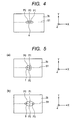
- the figure connecting the three focused spots P0, P1, and P2 draws a triangle as shown in Fig. 5(a) .
- the three focused spots P0, P1, and P2 fuse together to form a triangular heat source temperature distribution pattern f, and it is possible to cause the wedge effect to act in the left-hand direction.
- the figure connecting the four focused spots P0, P1, P2, and P3 draws a parallelogram, and that the two acute-angled vertexes P0 and P3 of the parallelogram are caused to be located on the projection line S1.
- the four focused spots P0, P1, P2, and P3 fuse together to form a parallelogrammatic heat source temperature distribution pattern g and the wedge effect acts in the left-hand and right-hand directions, and it is possible to further increase the processing speed in the cutting direction.
- the present embodiment by using an ultrashort pulse laser beam, it is possible to cause heat to be generated extremely locally and to achieve high temperature, and thus the present embodiment has the following two merits.
- the molten region is located locally, and thus the range in which the material changes into a ductile material is narrow and the brittleness on the periphery thereof is kept. As a result, cracks extend preferably when a thermal stress acts. When the pulse width is large, the molten range extends, and thus the extension of cracks due to change of the material into a ductile material is suppressed.
- the temperature gradient becomes steep. Consequently, a large thermal stress is generated.
- the pulse width is large, the temperature gradient becomes gradual because the peak power is small, and in addition, a state continues in which heat enters while heat is dissipated, and thus the temperature gradient becomes more gradual and it becomes harder for the thermal stress to be generated.
- the ultrashort pulse laser beam by using the ultrashort pulse laser beam, it becomes possible to perform irradiation by giving a time difference of the degree of the pulse width in the range of "simultaneity" defined within the present invention, and thus there is an advantage that it is possible to avoid the influence of heat generated by the pulse with which irradiation has been performed previously in terms of time.
- the optical system 2 in a laser processing method of the present embodiment includes, for example, the one shown in Fig. 6 .
- Reference numerals 22 and 23 in Fig. 6 denote beam splitters and reference numerals 24 and 25 denote mirrors.
- the laser beam emitted from the light source 1 is split into two by the beam splitter 22.
- the laser beam reflected by the beam splitter 22 is reflected by the mirror 24 and enters the conversing lens 21 at an angle ⁇ 0 between the beam and the optical axis O.
- the laser beam having passed through the beam splitter 22 is split further into two by the next beam splitter 23.
- the laser beam reflected by the beam splitter 23 is reflected by the mirror 25 and enters the condenser lens 21 at an angle ⁇ 1 between the beam and the optical axis O.
- the laser beam having passed through the beam splitter 22 travels on the optical axis O and enters the condenser lens 21.
- the laser beam having traveled on the optical axis O and having entered the condenser lens 21 is focused at the intersection of the projection line S1 and the optical axis O, and forms the focused spot P0.
- the laser beam having entered at ⁇ 0 between the beam and the optical axis O is focused at a position apart from the focused spot P0 by X0 on the projection line S1 and forms the focused spot P2.
- the laser beam having entered at ⁇ 1 between the beam and the optical axis O is focused at a position apart from the focused spot P0 by X1 on the projection line S1 and forms the focused spot P1.
- the optical paths of the laser beams forming the three focused spots P0, P1, and P2 are different and it is necessary to reduce the optical path difference so as to satisfy the above-mentioned "simultaneity".
- an optical delay medium By using an optical delay medium, it is possible to adjust the optical path difference.
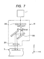
- a beam, the wavelength of which has shifted (first-order beam) and a beam, the wavelength of which has not shifted (zeroth-order beam) are generated by an acousto-optical modulator (AOM) 202 and inserted into a grating pair 203.
- AOM acousto-optical modulator
- Changing ⁇ by the change of the sound wave frequency of the AOM 202 or adjusting the number or dimension of gratings (pitch) of the grating pair 203 results in changing the angle of incidence upon the condenser lens 201, and thereby the position of the focused spot in the X direction is changed.
- Fig. 8 is an outline configuration diagram of a laser processing device of a second embodiment.
- Fig. 9 is a perspective view of the member 3 to be cut in Fig. 8
- Fig. 10 is a cross-sectional view along B-B line in Fig. 9 .
- the laser processing device of the present embodiment includes an optical system 2A that simultaneously forms a plurality of depth focused spots Q0 and Q1 in the depth direction at positions having a predetermined depth Z0 from the surface 3a of the member 3 to be cut and, at that time, forms at least one depth focused spot of the plurality of depth focused spots Q0 and Q1 on the optical axis O of a condenser lens 2A1.
- the focused spot Q0 is formed at the depth Z0 from the surface 3a on the optical axis O and the focused spot Q1 is formed at a position deeper in the depth direction (Z direction) than the focused spot Q0 on the optical axis O.
- the two focused spots Q0 and Q1 are formed sequentially in the X direction.
- the two focused spots Q0 and Q1 partially overlap or are in contact with or close to each other, and thus they fuse together and form the elliptic spot e as shown in Fig. 10(a) .
- the two focused spots Q0 and Q1 are located on the optical axis O, and thus the major axis of the elliptic spot e is also located on the optical axis O.
- stress anisotropy that is, a stress that causes cracks to grow in the major axis direction (depth direction) is generated and it is possible to increase the interval in the depth direction at which the other spots Q0 and Q1 are simultaneously formed in the depth direction. That is, it is possible to increase the feeding speed of the mobile stage in the Z axis direction (processing speed in the thickness direction).
- the two focused spots Q0 and Q1 are simultaneously formed, and thus there is not a problem in which a sufficient amount of energy does not reach the focal point or in which the position of the focal point shifts.
- a modified aspect of the second embodiment will be explained.
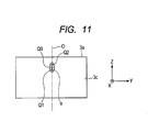
- the two focused spots Q0 and Q1 may also be possible to form the two focused spots Q0 and Q1 at an interval larger than a predetermined interval.
- the two focused spots Q0 and Q1 no longer fuse together but form the independent circular heat source temperature distribution patterns ⁇ 0 and ⁇ 1.
- a tensile stress works, and the extension of cracks in the direction of the optical axis O (thickness direction) is promoted.
- the figure connecting the three focused spots Q0, Q1, and Q2 it is preferable for the figure connecting the three focused spots Q0, Q1, and Q2 to draw a triangle as shown in Fig. 12(a) .
- the three focused spots Q0, Q1, and Q2 fuse together and form the triangular heat source temperature distribution pattern f and it is possible to cause the wedge effect to act in the upward direction.
- Fig. 12(b) it may also be possible to cause the figure connecting the four focused spots Q0, Q1, Q2, and Q3 to draw a parallelogram and to cause the two acute-angled vertexes Q0 and Q3 of the parallelogram, to be located on the optical axis O.
- the four focused spots Q0, Q1, Q2, and Q3 fuse together and form the parallelogrammatic heat source temperature distribution pattern g and the wedge effect acts in the vertical direction, and thus it is possible to further increase the processing speed in the thickness direction.
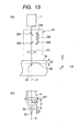
- the optical system 2A in the laser processing device of the present embodiment includes, for example, the one shown in Fig. 13 .
- reference numerals 2A2 and 2A3 denote beam splitters and reference numerals 2A4 and 2A5 denote mirrors.
- Reference numeral 2A6 denotes a relay lens.
- the laser beam emitted from the light source 1 is split into two by the beam splitter 2A2.
- the laser beam having passed through the beam splitter 2A2 passes through the beam splitter 2A3 and enters the condenser lens 2A1.
- the laser beam reflected by the beam splitter 2A2 is converted into a laser beam having a spread angle ⁇ by the relay optical system 2A6 and then is reflected by the beam splitter 2A3 and enters the condenser lens 2A1.
- the laser beam having passed through the beam splitter 2A3 is focused in the focus position of the condenser lens 2A1 as shown in Fig. 13(b) and forms the focused spot Q0.
- the laser beam reflected by the beam splitter 2A3 is focused at a position Z1 lower than the focused spot Q0 and forms the focused spot Q1.
- the optical paths of the laser beams forming the two focused spots Q0 and Q1 are different and it is necessary to reduce the optical path difference through the use of an optical delay medium or the like so as to satisfy the above-mentioned simultaneity.
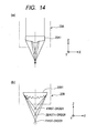
- optical system 2A it is possible to use optical systems 20A and 20B shown in Fig. 14 .
- Fig. 14(a) it is possible to separate focused spots by using a multifocal lens 20A1 in which the curvature at the center part is different from that on the periphery.
- a method for separating focused spots in the Z direction is illustrated, but it is also possible to separate focused spots in the X direction.
- a diffractive lens Resnel lens
- Fig. 15 is an outline configuration diagram of a laser processing device of a third embodiment.
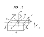
- Fig. 16 is a perspective view of the member 3 to be cut in Fig. 15
- Fig. 17(a) is a cross-sectional view along A-A line in Fig. 16
- Fig. 17(b) is a cross-sectional view along B-B line in Fig. 16 .
- the laser processing device of the present embodiment includes an optical system 2B that simultaneously forms a plurality of cross-sectional focused spots P0 and P1 on the section 3b which is perpendicular to the optical axis O of a condenser lens 2B1 at a position at the predetermined depth Z0 from the surface 3a of the member 3 to be cut and which is parallel to the surface 3a, at that time, forms at least one cross-sectional focused spot of the plurality of cross-sectional focused spots P0 and P1 on the projection line S1 of the planned cutting line S0 onto the cross section 3b, simultaneously forms a plurality of depth focused spots Q0 and Q1 also at a position at the predetermined depth Z0 in the depth direction, and, at that time, forms at least one depth focused spot of the plurality of depth focused spots Q0 and Q1 on the optical axis O of the condenser lens 2B1.
- the two focused spots P0 and P1 are formed on the projection line S1 of the planned cutting line S0 onto the cross section (XY plane) 3b, the focused spot Q0 is formed in the position deep from the surface 3a by Z0 on the optical axis O, and the focused spot Q1 is formed at a position (deep from the surface 3a by (Z0 + Z1)) deeper than the focused spot Q0 on the optical axis O.
- the two focused spots P0 and P1 are in contact with or close to each other, and thus they fuse together in a short time period and form an elliptic spot e1 as shown in Fig. 17(a) . Because the two focused spots P0 and P1 are located on the projection line S1, the major axis of the elliptic heat source temperature distribution pattern e1 is located also on the projection line S1. As a result, stress anisotropy, that is, a stress that causes cracks to grow in the major axis direction is generated and it is possible to increase the interval at which the next two spots P0 and P1 are formed. Accordingly, it is possible to increase the feeding speed of the mobile stage in the X axis direction (processing speed in the cutting direction).
- the two focused spots Q0 and Q1 partially overlap or are in contact with or close to each other, and thus, they fuse together in a short time period and form an elliptic spot e2 as shown in Fig. 17(b) .
- the major axis of the elliptic heat source temperature distribution pattern e2 is located also on the optical axis O.
- stress anisotropy that is, a stress that causes cracks to grow in the major axis direction (depth direction) is generated and it is possible to increase the interval in the depth direction at which the other spots Q0 and Q1 are simultaneously formed in the depth direction. That is, it is possible to increase the amount by which the focus position is shifted in the thickness direction and to increase the processing speed in the thickness direction (the relative movement speed in the thickness direction of the condenser lens).
- the optical system 2B in the laser processing device of the present embodiment includes, for example, the one as shown in Fig. 18 .
- reference numerals 2B2, 2B3, 2B4, and 2B5 denote beam splitters
- reference numerals 2B6, 2B7, 2B8, and 2B9 denote mirrors
- reference numerals 2B10 and 2B11 denote relay lenses.
- the laser beam emitted from the light source 1 is split into two by the beam splitter 2B2 and one of the laser beams is further split by the beam splitter 2B3.
- the laser beam having passed through the beam splitter 2B2 passes through the beam splitters 2B3, 2B4, and 2B5, and enters the condenser lens 2B1 to form the focused spot P0 (Q0).
- the laser beam reflected by the beam splitter 2B2 is converted into a laser beam having the spread angle ⁇ by the relay lens 2B10. Then, the laser beam is reflected by the beam splitter 2B4, enters the condenser lens 2B1, and forms the focused spot Q1. It should be noted that it is possible to change the spread angle by changing the lens interval of the relay lens 2B10 (distance in the Z direction).
- the propagation direction of the laser beam reflected by the beam splitter 2B3 is changed by the relay lens 2B11. Then, the laser beam is reflected by the beam splitter 2B5 and enters the condenser lens 2B1 in the direction forming 6 between the beam and the optical axis O and forms the focused spot P1. Meanwhile, when the magnification of the relay lens 2B11 is large, it is possible to change the propagation direction by changing a tilt angle of the relay lens 2B11.
- An optical system 2C as shown in Fig. 19 may be used in place of the optical system 2B.
- the optical system 2C independently reflect second-order and higher-order diffracted beams obtained by a diffraction grating 2C2, at mirrors 2C3 to 2C7 and focuses returned beams at a condenser lens 2C1.
- ⁇ i is an angle of incidence upon the diffraction grating 2C2
- ⁇ t is an emission angle from the diffraction grating 2C2.
- an optical system 2D as shown in Fig. 20 may be used in place of the optical system 2B.
- One beam emitted from the light source 1 is expanded by a beam expander 2D2 and is caused to enter glass rods 2D6 to 2D8 attached to a number of apertures 2D3 to 2D5.
- a beam expander 2D2 By changing the end surface angle on the emission side of the glass rods 2D6 to 2D8, it is possible to change the angle of the beam incident upon a condenser lens 2D1 and to change the position of the focused spot in the X direction.
- each spread angle or narrowed angle
- the curvature of the end surface on the emission side of the glass rods 2D6 to 2D8 it is possible to change each spread angle (or narrowed angle) when entering the condenser lens 2D1 and to change the position in the Z direction.
- a SELFOC lens lens having a refractive index distribution in which the refractive index becomes smaller toward the outside of the radius
- the intensity distribution between focal points after separation is also similar to a Gaussian one.
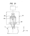
- an optical system 2E as shown in Fig. 21 may be used in place of the optical system 2B.
- a beam emitted from the light source 1 is separated into a beam having a small center and a doughnut-shaped beam through the use of an axicon mirror pair 2E2 having a hole and is focused by a condenser lens 2E1.
- the length of a delay medium 2E3 is adjusted so that the optical path length returned within the axicon mirror pair 2E2 and the effective optical path length within the delay medium 2E3 are made uniform.
- the main simulation conditions are as follows:
- Fig. 22 The simulation results are shown in Fig. 22 .
- Fig. 22(a) When about 10 ps elapsed after irradiation of the laser pulse, an elliptic heat source temperature distribution pattern shown in Fig. 22(a) was formed.
- Fig. 22(b) shows the elliptic heat source temperature distribution pattern 10 ns after that in Fig. 22(a) .
- the temperature of the deepest black region in the center was about 4,000°K, that of the whitish region on the outside was about 1,500°K, and that of the intermediate region was 2,500 to 3,000°K.
- the main simulation conditions are as follows:
- Fig. 23 shows heat source temperature distribution patterns when 10 nsec elapsed after forming three focused spots, in which (a) shows a heat source temperature distribution pattern when the three focused spots were formed with a time difference of 0, (b) shows a heat source temperature distribution pattern when the middle focused spot was formed 0.003 nsec after forming the focused spots on both sides, (c) shows a heat source temperature distribution pattern when the focused spots on both ends were formed 0.003 nsec after forming the middle focused spot, (d) shows a heat source temperature distribution pattern when the middle focused spot was formed 0.03 nsec after forming the focused spots on both sides, (e) shows a heat source temperature distribution pattern when the focused spots on both ends were formed 0.03 nsec after forming the middle focused spot, (f) shows a heat source temperature distribution pattern when the middle focused spot was formed 0.3 nsec after forming the focused spots on both sides, and (g) shows a heat source temperature distribution pattern when the focused spots on both ends were formed 0.3
- the main simulation conditions are as follows:
- Fig. 24 and Fig. 25 show heat source temperature distribution patterns and stress distribution patterns when the focused spot center interval is 2 ⁇ m and 4 ⁇ m, respectively (the case in which the focused spot center interval is 6 ⁇ m is omitted).
- Fig. 26 is a graph in which the maximum stress of the stress distribution pattern in Fig. 24 etc. is taken along the vertical axis and the focused spot interval is taken along the horizontal axis.
- the main simulation conditions are as follows:
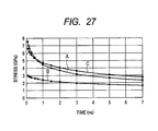
- the simulation results are shown in Fig. 27 .
- the center temperature of the heat source about 100 ps after irradiation with the laser pulse reached 9,843°K and the maximum stress was exhibited at that time (at the time point of 0 ns on the horizontal axis in Fig. 27 ).
- a curve A represents the stress in the Y direction and a curve B represents the stress in the X direction and it can be found from Fig. 27 that the tensile stress in the direction perpendicular to the major axis of the elliptic heat source temperature distribution pattern (Y direction) is larger than the tensile stress in the major axis direction (X direction).
- a stress curve C of a circular heat source is also shown. From this, immediately after the elliptic heat source temperature distribution pattern is generated, it can also be found that a tensile stress of the elliptic heat source larger than that of the circular heat source acts, but the cooling speed of the elliptic heat source is larger than that of the circular heat source, and thus the tensile stress of the elliptic heat source becomes smaller than that of the circular heat source after the elapse of a predetermined period of time.
- a processing experiment was conducted through the use of the laser processing device of the first embodiment.
- the processing conditions are as follows:
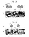
- Light source 1 Mode locked fiber laser having the following specifications and performance (IMRA America, Inc. Model D1000) Center frequency : 1,045 nm Beam diameter : 4 mm Mode : Single (Gaussian) Pulse width : 700 fs Pulse energy : 10 ⁇ J (maximum) Repetitive frequency : 100 kHz (maximum) Average power : 1,000 mW (maximum) Condenser lens 21 : Microscope objective (focal length: 4 mm, numerical aperture: 0.65) Focused spot diameter: 2 ⁇ m Member 3 to be cut: Sapphire Number of simultaneous focused spots: 2 Focused spot center interval: 2 ⁇ m Stage scanning speed: 1,000 mm / s (interval between neighboring two focused spots is 10 ⁇ m, see Fig. 28(a) ).
- Fig. 28(b) is a radiographic image of sapphire internally processed. It can be seen that cracks extend uniformly in the cutting direction from the two simultaneous focused spots.
- the processing conditions are the same as those in the above-mentioned example except that the number of simultaneous focused spots is set to 1 and the stage scanning speed is set to 500 mm / s (spot interval is 5 ⁇ m, see Fig. 29(a) ) in the processing conditions in the above-mentioned example.
- Fig. 29(b) is a radiographic image of sapphire internally processed. It can be seen that excess cracks that do not contribute to cutting are generated in a direction different from the direction in which the focused spots are connected (crystal orientation).
Landscapes
- Physics & Mathematics (AREA)
- Optics & Photonics (AREA)
- Engineering & Computer Science (AREA)
- Mechanical Engineering (AREA)
- Plasma & Fusion (AREA)
- Chemical & Material Sciences (AREA)
- Health & Medical Sciences (AREA)
- Toxicology (AREA)
- Materials Engineering (AREA)
- Thermal Sciences (AREA)
- Organic Chemistry (AREA)
- Oil, Petroleum & Natural Gas (AREA)
- General Chemical & Material Sciences (AREA)
- Chemical Kinetics & Catalysis (AREA)
- Laser Beam Processing (AREA)
- Processing Of Stones Or Stones Resemblance Materials (AREA)
- Re-Forming, After-Treatment, Cutting And Transporting Of Glass Products (AREA)
- Dicing (AREA)
Abstract
Description
- The present invention relates to a laser processing method and a laser processing device for forming a modification region serving as a starting point of cutting, inside a member to be cut, by irradiating the member to be cut with focused laser light along a planned cutting line on the member to be cut.
- Conventionally, when cutting a hard and brittle material plate such as a semiconductor substrate, a piezoelectric ceramic substrate, a sapphire substrate, and a glass substrate, a short-pulse laser having a wavelength transparent to the plate is focused and irradiated to the inside of a plate to be cut along a planned cutting line, to thereby generate a fine molten trace (modification region), inside which micro cracks grow gregariously, and then a stress is applied and the plate is divided by utilizing cracks caused toward the direction of the plate thickness from the fine molten trace as a starting point (for example, see Patent Document 1).
- Furthermore, a processing method is also known, in which one pulse laser beam is divided into three and a time difference is given between them (the second beam is delayed from the first beam and the third beam is delayed from the second beam) and then positions shifted from one another are irradiated with the three focused laser beams (for example, see Patent Document 2).
- Patent Document 1: Japanese Patent Application Laid-Open No.
2005-271563 - Patent Document 2: Japanese Patent Application Laid-Open No.
2006-167804 - However, by the conventional laser processing method described above, the laser beam is focused in a circular spot, and thus an inside stress that causes cracks to be generated and grow works isotropically. Because of this, cracks are generated and grow in directions other than the direction along the planned cutting line, and it is not possible to centralize the generation and growth of cracks in the direction of the planned cutting line. As a result, the flatness of the divided section is impaired. Furthermore, there is also a problem in which when a circular spot is irradiated along the planned cutting line, the number of irradiation spots per unit length increases, and thus the processing speed is slow. Moreover, when the plate to be cut is thick, it is necessary to repeat processing while shifting the focus position in the thickness direction, but the amount by which the position is shifted in the thickness direction has to be reduced, and thus the processing speed is further lowered.
- As to the processing method in which one pulse laser beam is divided into three and a time difference is given between them, and then positions shifted from one another are irradiated with the three focused laser beams, it is expected that the processing speed in the direction of the planned cutting line (relative movement speed of the optical axis of the condenser lens) can be increased by connecting and forming the three spots in the direction of the planned cutting line. Furthermore, by connecting and forming the three spots in the thickness direction, it is expected that the amount by which the focus position is shifted in the thickness direction can be increased, and the processing speed in the thickness direction (relative movement speed in the thickness direction of the condenser lens) can be increased.
- However, excluding the first pulse beam with which first irradiation is performed among the three pulse beams with which continuous irradiation is performed, with a time difference, the subsequent pulse beams are affected by the heat generated by the pulse beam with which previous irradiation was performed. When the brittle material that is the member to be cut is heated to temperatures at which amorphous transition occurs, the material changes into a ductile material, and thus even if the brittle material is irradiated with the subsequent pulse beams in the vicinity of the region heated by the previous pulse beam, it becomes harder for the stress caused by a temperature difference to be generated and at the same time, it becomes harder for cracks to grow because of the influence of the change in the physical properties of the material (for example, dissolution). As a result, the processing speed is not increased as expected.
- Furthermore, the refractive index and absorption coefficient of the brittle material that is the member to be cut, for a laser beam also change depending on temperature, and thus, even if the brittle material is irradiated with the subsequent pulse beams in the vicinity of the region heated by the previous pulse beam, the laser beam is absorbed before reaching a focal point and there is also a problem in which a sufficient amount of energy does not reach the focal point or in which the position of the focal point shifts. If the position of the focal point shifts, the three spots cannot be connected in the thickness direction and it is not possible to increase the amount by which the focus position is shifted in the thickness direction. As a result, the processing speed in the thickness direction (relative movement speed in the thickness direction of the condenser lens) is reduced.
- The present invention has been made in view of the above-mentioned problems and an object thereof is to provide a laser processing method and a laser processing device having a high processing speed and high energy efficiency.
- A laser processing method of the present invention made in order to solve the above-mentioned problems is a laser processing method for forming a modification region serving as a starting point of cutting inside a member to be cut along a planned cutting line by relatively moving an optical axis of a condenser lens along the planned cutting line of the member to be cut and by irradiating the member to be cut with focused laser light, wherein a plurality of cross-sectional focused spots is simultaneously formed at positions on a cross section which is perpendicular to the optical axis of the condenser lens at positions having a predetermined depth from a surface of the member to be cut and which is parallel to the surface and, at that time, at least one cross-sectional focused spot of the plurality of cross-sectional focused spots is formed on a projection line of the planned cutting line onto the cross section to form one or more inside modification regions having a desired shape.
- Furthermore, another laser processing method of the present invention made in order to solve the above-mentioned problems is a laser processing method for forming a modification region serving as a starting point of cutting inside a member to be cut along a planned cutting line by relatively moving an optical axis of a condenser lens along the planned cutting line of the member to be cut and by irradiating the member to be cut with focused laser light, wherein a plurality of depth focused spots is simultaneously formed in the depth direction at positions having a predetermined depth from a surface of the member to be cut and, at that time, at least one depth focused spot of the plurality of depth focused spots is formed on the optical axis of the condenser lens to form one or more inside modification regions having a desired shape.
- Moreover, still another laser processing method of the present invention made in order to solve the above-mentioned problems is a laser processing method for forming a modification region serving as a starting point of cutting inside a member to be cut along a planned cutting line by relatively moving an optical axis of a condenser lens along the planned cutting line of the member to be cut and by irradiating the member to be cut with focused laser light, wherein a plurality of cross-sectional focused spots is simultaneously formed at positions on a cross section which is perpendicular to the optical axis of the condenser lens at positions having a predetermined depth from a surface of the member to be cut and which is parallel to the surface and, at that time, at least one cross-sectional focused spot of the plurality of cross-sectional focused spots is formed on a projection line of the planned cutting line onto the cross section, a plurality of depth focused spots is simultaneously formed also in the depth direction at the positions having the predetermined depth and, at that time, at least one depth focused spot of the plurality of depth focused spots is formed on the optical axis of the condenser lens, and thereby one or more inside modification regions having a desired shape are formed.
- In the laser processing method described above, it is preferable for the laser beam to be an ultrashort pulse laser beam.
- In addition, in the laser processing method described above, it is only necessary for the figure connecting the plurality of cross-sectional focused spots to be a triangle.
- Moreover, it is only necessary for the figure connecting the plurality of depth focused spots to be a triangle.
- Furthermore, it is only necessary for the figure connecting the plurality of cross-sectional focused spots to be a parallelogram, and for two acute-angled vertexes of the parallelogram, to be located on a projection line of the planned cutting line onto the cross section.
- In addition, it is only necessary for the figure connecting the plurality of depth focused spots to be a parallelogram, and for two acute-angled vertexes of the parallelogram, to be located on the optical axis of the condenser lens.
- Furthermore, it is only necessary to form the inside modification region having a desired shape by using a combination of spatial positions of the plurality of cross-sectional focused spots on the section and an energy density of the focused spot.
- Moreover, it is only necessary to form the inside modification region having a desired shape by using a combination of spatial positions of the plurality of depth focused spots in a plane including the planned cutting line and an energy density of the focused spot.
- A laser processing device of the present invention made in order to solve the above-mentioned problems is a laser processing device for forming a modification region serving as a starting point of cutting inside a member to be cut along a planned cutting line by relatively moving an optical axis of a condenser lens along the planned cutting line of the member to be cut and by irradiating the member to be cut with focused laser light, comprising: an optical system which simultaneously forms a plurality of cross-sectional focused spots at positions on a cross section which is perpendicular to the optical axis of the condenser lens at positions having a predetermined depth from a surface of the member to be cut and which is parallel to the surface and, at that time, which forms at least one cross-sectional focused spot of the plurality of cross-sectional focused spots on a projection line of the planned cutting line onto the cross section, wherein one or more inside modification regions having a desired shape are formed.
- Furthermore, another laser processing device of the present invention made in order to solve the above-mentioned problems is a laser processing device for forming a modification region serving as a starting point of cutting inside a member to be cut along a planned cutting line by relatively moving an optical axis of a condenser lens along the planned cutting line of the member to be cut and by irradiating the member to be cut with focused laser light, comprising: an optical system that simultaneously forms a plurality of depth focused spots in the depth direction at positions having a predetermined depth from a surface of the member to be cut and, at that time, forms at least one depth focused spot of the plurality of depth focused spots on the optical axis of the condenser lens, wherein one or more inside modification regions having a desired shape are formed.
- Moreover, still another laser processing device of the present invention made in order to solve the above-mentioned problems is a laser processing device for forming a modification region serving as a starting point of cutting inside a member to be cut along a planned cutting line by relatively moving an optical axis of a condenser lens along the planned cutting line of the member to be cut and by irradiating the member to be cut with focused laser light, comprising: an optical system that simultaneously forms a plurality of cross-sectional focused spots at positions on a cross section which is perpendicular to the optical axis of the condenser lens at positions having a predetermined depth from a surface of the member to be cut and which is parallel to the surface, at that time, forms at least one cross-sectional focused spot of the plurality of cross-sectional focused spots on a projection line of the planned cutting line onto the cross section, simultaneously forms a plurality of depth focused spots also in the depth direction at the positions having the predetermined depth and, at that time, and forms at least one depth focused spot of the plurality of depth focused spots on the optical axis of the condenser lens, wherein one or more inside modification regions having a desired shape are formed.
- A plurality of cross-sectional focused spots is simultaneously formed at positions on a cross section which is perpendicular to the optical axis of the condenser lens at positions having a predetermined depth from a surface of a member to be cut and which is parallel to the surface, and thus the generation of a stress due to change of the material into a ductile material is not suppressed or the extension of cracks by the change in physical properties is not suppressed, and the processing speed in the direction of the planned cutting line is increased.
- A plurality of depth focused spots is simultaneously formed in the depth direction at positions having a predetermined depth from a surface of a member to be cut, and thus the generation of a stress due to change of the material into a ductile material is not suppressed or the extension of cracks by the change in physical properties is not suppressed, and the processing speed in the thickness direction is increased.
- A plurality of cross-sectional focused spots is simultaneously formed at positions on a cross section which is perpendicular to the optical axis of the condenser lens at positions having a predetermined depth from a surface of a member to be cut and a plurality of depth focused spots is simultaneously formed also in the depth direction at positions having a predetermined depth, and thus it is possible to increase both the processing speed in the direction of the planned cutting line and the processing speed in the thickness direction.
- When the laser beam is an ultrashort pulse laser beam, even if one laser beam is branched into a plurality of laser beams, the peak value of the pulse of each laser beam has a sufficient margin for a fixed threshold value necessary for amorphous phase transition. Furthermore, pulse irradiation is completed before a heat source is generated, and thus the pulse itself is not affected by heat and it is possible to stably control cracks by a desired heat source.
- The figure connecting the plurality of cross-sectional focused spots is a triangle, and thus the wedge effect works in one direction of the direction of the planned cutting line and it is possible to further increase the processing speed in the direction of the planned cutting line.
- The figure connecting the plurality of depth focused spots is a triangle, and thus the wedge effect works in one direction of the thickness direction and it is possible to further increase the processing speed in the thickness direction.
- The figure connecting the plurality of cross-sectional focused spots is a parallelogram and two acute-angled vertexes of the parallelogram are located on a projection line of the planned cutting line onto the cross section, and thus the wedge effect works in both directions of the directions of the planned cutting line and it is possible to further increase the processing speed in the direction of the planned cutting line.
- The figure connecting the plurality of depth focused spots is a parallelogram and two acute-angled vertexes of the parallelogram are located on the optical axis of the condenser lens, and thus the wedge effect works in both directions of the thickness directions and it is possible to further increase the processing speed in the thickness direction.
- The inside modification region having a desired shape is formed by using a combination of spatial positions of the plurality of cross-sectional focused spots on the section and an energy density of the focused spot, and thus it is possible to freely control the working of the wedge effect in the direction of the planned cutting line.
- The inside modification region having a desired shape is formed by using a combination of spatial positions of the plurality of depth focused spots in a plane including the planned cutting line and an energy density of the focused spot, and thus it is possible to freely control the working of the wedge effect in the thickness direction.
-
-
Fig. 1 is an outline configuration diagram of a laser processing device of a first embodiment according to the present invention. -
Fig. 2 is a perspective view of amember 3 to be cut inFig. 1 . -
Fig. 3 is a cross-sectional view along A-A line inFig. 1 . -
Fig. 4 is a cross-sectional view along A-A line inFig. 1 for explaining a modified aspect of the first embodiment. -
Fig. 5 is a cross-sectional view along A-A line inFig. 1 for explaining another modified aspect of the first embodiment. -
Fig. 6 is a diagram showing an example of an optical system in the laser processing device of the first embodiment. -
Fig. 7 is a diagram showing a modified aspect of the optical system inFig. 6 . -
Fig. 8 is an outline configuration diagram of a laser processing device of a second embodiment. -
Fig. 9 is a perspective view of themember 3 to be cut inFig. 8 . -
Fig. 10 is a cross-sectional view along B-B line inFig. 9 . -
Fig. 11 is a cross-sectional view along B-B line inFig. 9 for explaining a modified aspect of the second embodiment. -
Fig. 12 is a cross-sectional view along B-B line inFig. 9 for explaining another modified aspect of the second embodiment. -
Fig. 13 is a diagram showing an example of an optical system in the laser processing device of the second embodiment. -
Fig. 14 is a diagram showing a modified aspect of the optical system inFig. 13 . -
Fig. 15 is an outline configuration diagram of a laser processing device of a third embodiment. -
Fig. 16 is a perspective view of themember 3 to be 3 inFig. 15 . -
Fig. 17 is a cross-sectional view along A-A line and a cross-sectional view along B-B line inFig. 16 . -
Fig. 18 is a diagram showing an example of an optical system in the laser processing device of the third embodiment. -
Fig. 19 is a diagram showing a modified aspect of the optical system inFig. 18 . -
Fig. 20 is a diagram showing another modified aspect of the optical system inFig. 18 . -
Fig. 21 is a diagram showing still another modified aspect of the optical system inFig. 18 . -
Fig. 22 shows heat source temperature distribution patterns immediately after two focused spots are formed. -
Fig. 23 shows heat source temperature distribution patterns after 10 nsec when forming three focused spots by varying time difference τ. -
Fig. 24 shows heat source temperature distribution patterns and stress distribution patterns when the interval between two focused spots (spot diameter: 2 µm) is 2 µm. -
Fig. 25 shows heat source temperature distribution patterns and stress distribution patterns when the interval between two focused spots (spot diameter: 2 µm) is 4 µm. -
Fig. 26 is a graph showing a relation between the interval between focused spots and the stress. -
Fig. 27 is a graph showing a change of the stress with time. -
Fig. 28 shows a diagram for explaining a spatial arrangement of the focused spots in an example and a radiograph of sapphire after laser processing. -
Fig. 29 shows a diagram for explaining a spatial arrangement of the focused spots in a comparative example and a radiograph of sapphire after laser processing. -
- 21, 201, 2A1, 20A1, 20B1, 2B1, 2C1, 2D1, 2E1: condenser lens
- O: optical axis
- S0: planned cutting line
- 3: member to be cut
- 3a: surface
- 3b: cross section
- P0, P1, P2, P3: cross-sectional focused spot
- Q0, Q1, Q2, Q3: depth focused spot
- 2, 20, 2A, 20A, 20B, 2B, 2C, 2D, 2E: optical system
- Embodiments for embodying the present invention will be explained below in detail based on the drawings.
-
Fig. 1 is an outline configuration diagram of a laser processing device of a first embodiment.Fig. 2 is a perspective view of amember 3 to be cut inFig. 1 andFig. 3 is a cross-sectional view along A-A line inFig. 1 . - As shown in
Fig. 1 to Fig. 3 , the laser processing device of the present embodiment comprises anoptical system 2 that simultaneously forms a plurality of cross-sectional focused spots P0 and P1 on asection 3b which is perpendicular to an optical axis O of acondenser lens 21 at positions having a predetermined depth Z0 from asurface 3a of themember 3 to be cut and which is parallel to thesurface 3a and at that time, forms at least one cross-sectional focused spot of the plurality of cross-sectional focused spots P0 and P1 on a projection line S1 of a planned cutting line S0 onto thecross section 3b. -
Reference numeral 1 denotes a light source that generates a repetitive ultrashort pulse laser beam having a wavelength transparent to themember 3 to be cut. By using a mode locked fiber laser doped with Er or Yb, which generates a laser beam having a wavelength of 1 to 2 µm, a pulse width of 10 fs to 20 ps, and a repetitive frequency of 100 kHz to 10 MHz as thelight source 1, the laser beam is multiphoton-absorbed in a focused spot position of themember 3 to be cut, such as glass, sapphire, quartz, and silicon, and an inside modification region is formed. - In the present embodiment, the two focused spots P0 and P1 are formed on the projection line S1 of the planned cutting line S0 onto the
cross section 3b. By moving a mobile stage, not shown schematically, in an X direction, the pair of the two focused spots P0 and P1 is formed sequentially on S1. - Because the two focused spots P0 and P1 are in contact with or close to each other, they fuse together within a short time period and form an elliptic heat source temperature distribution pattern e as shown in
Fig. 3(a) . Since the two focused spots P0 and P1 are located on the projection line S1, the major axis of the elliptic heat source temperature distribution pattern e is also located on the projection line S1. As a result, stress anisotropy, that is, a stress that causes cracks to grow in the major axis direction occurs within themember 3 to be cut, and thus it is possible to increase the interval at which the next two spots P0 and P1 are formed. That is, it is possible to increase the feeding speed of the mobile stage in the X direction (processing speed in the cutting direction). - Furthermore, the two focused spots P0 and P1 are simultaneously formed, and thus there is not a problem in which a sufficient amount of energy does not reach the focal point or in which the position of the focal point shifts.
- Next, a modified aspect of the first embodiment will be explained. It may also be possible to form the two focused spots P0 and P1 so that an interval between the two focused spots P0 and P1 is enlarged to set the interval to a predetermined interval, as shown in
Fig. 3(b) . In this case, the two focused spots P0 and P1 no longer fuse together but form independent circular heat source temperature distribution patterns γ0 and γ1. Between the independent circular heat source temperature distribution patterns γ0 and γ1, a tensile stress works and the extension of cracks in the direction of the projection line S1 (cutting direction) is promoted. - Moreover, it may also be possible to simultaneously form the three focused spots P0, P1, and P2 as shown in
Fig. 4 . At that time, by setting energy densities to be injected into P0, P1, and P2 as E0, E1, and E2, respectively, satisfying E0 > E1 and E0 > E2 results in an increase of the stress anisotropy (wedge effect), and thus it is possible to furthermore increase the processing speed. - It is preferable that the figure connecting the three focused spots P0, P1, and P2 draws a triangle as shown in
Fig. 5(a) . The three focused spots P0, P1, and P2 fuse together to form a triangular heat source temperature distribution pattern f, and it is possible to cause the wedge effect to act in the left-hand direction. - Furthermore, it may also be possible that the figure connecting the four focused spots P0, P1, P2, and P3 draws a parallelogram, and that the two acute-angled vertexes P0 and P3 of the parallelogram are caused to be located on the projection line S1. The four focused spots P0, P1, P2, and P3 fuse together to form a parallelogrammatic heat source temperature distribution pattern g and the wedge effect acts in the left-hand and right-hand directions, and it is possible to further increase the processing speed in the cutting direction.
- Here, "simultaneity" in simultaneously forming a plurality of focused spots in the present invention will be explained. It is impossible to simultaneously form a plurality of focused spots in spatially different positions and there is naturally a time width (time difference) τ among the plurality of focused spots. Therefore, it has been investigated to what extent the time difference τ is allowed by simulation experiments (see
Simulation 2, to be described later). As a result, when the member to be cut is typical sapphire, τ = 0.3 nsec was obtained. Because of this, in the present invention, a range between 0 and subnano sec is defined as "simultaneity". - Like in the present embodiment, by using an ultrashort pulse laser beam, it is possible to cause heat to be generated extremely locally and to achieve high temperature, and thus the present embodiment has the following two merits.
- First, the molten region is located locally, and thus the range in which the material changes into a ductile material is narrow and the brittleness on the periphery thereof is kept. As a result, cracks extend preferably when a thermal stress acts. When the pulse width is large, the molten range extends, and thus the extension of cracks due to change of the material into a ductile material is suppressed.
- Next, since the peak power is high, the temperature gradient becomes steep. Consequently, a large thermal stress is generated. When the pulse width is large, the temperature gradient becomes gradual because the peak power is small, and in addition, a state continues in which heat enters while heat is dissipated, and thus the temperature gradient becomes more gradual and it becomes harder for the thermal stress to be generated.
- When irradiation with a plurality of beams is simultaneously performed and the interval between each spot is about five times or less the wavelength, that is, narrow, beams interfere with one another and there is a possibility that the intensity distribution varies depending on the degree of the interference, and thus it is necessary to perform processing that has taken into account the influence. Consequently, in order to maintain the intended intensity distribution and to obtain a desired heat source temperature distribution pattern more effectively, it is desirable to irradiate each beam while providing a time difference of the degree of the pulse width between each beam. Like in the present embodiment, by using the ultrashort pulse laser beam, it becomes possible to perform irradiation by giving a time difference of the degree of the pulse width in the range of "simultaneity" defined within the present invention, and thus there is an advantage that it is possible to avoid the influence of heat generated by the pulse with which irradiation has been performed previously in terms of time.
- The
optical system 2 in a laser processing method of the present embodiment includes, for example, the one shown inFig. 6 .Reference numerals Fig. 6 denote beam splitters andreference numerals - The laser beam emitted from the
light source 1 is split into two by thebeam splitter 22. The laser beam reflected by thebeam splitter 22 is reflected by themirror 24 and enters the conversinglens 21 at an angle θ0 between the beam and the optical axis O. The laser beam having passed through thebeam splitter 22 is split further into two by thenext beam splitter 23. The laser beam reflected by thebeam splitter 23 is reflected by themirror 25 and enters thecondenser lens 21 at an angle θ1 between the beam and the optical axis O. The laser beam having passed through thebeam splitter 22 travels on the optical axis O and enters thecondenser lens 21. - The laser beam having traveled on the optical axis O and having entered the
condenser lens 21 is focused at the intersection of the projection line S1 and the optical axis O, and forms the focused spot P0. The laser beam having entered at θ0 between the beam and the optical axis O is focused at a position apart from the focused spot P0 by X0 on the projection line S1 and forms the focused spot P2. The laser beam having entered at θ1 between the beam and the optical axis O is focused at a position apart from the focused spot P0 by X1 on the projection line S1 and forms the focused spot P1. - If the focal length of the
condenser lens 21 is defined as F, there is a relation expressed by

- In the
optical system 2 inFig. 6 , the optical paths of the laser beams forming the three focused spots P0, P1, and P2 are different and it is necessary to reduce the optical path difference so as to satisfy the above-mentioned "simultaneity". By using an optical delay medium, it is possible to adjust the optical path difference. - Next, a modified aspect of the
optical system 2 will be explained. As theoptical system 2, it is possible to use anoptical system 20 shown inFig. 7 . A beam, the wavelength of which has shifted (first-order beam) and a beam, the wavelength of which has not shifted (zeroth-order beam) are generated by an acousto-optical modulator (AOM) 202 and inserted into agrating pair 203. By thegrating pair 203, the optical path difference between the two beams is adjusted so as to satisfy simultaneity. Changing θ by the change of the sound wave frequency of theAOM 202 or adjusting the number or dimension of gratings (pitch) of thegrating pair 203 results in changing the angle of incidence upon thecondenser lens 201, and thereby the position of the focused spot in the X direction is changed. - It is possible to control the position of the focused spot by changing the sound wave frequency of the
AMO 202 according to an electric signal from outside. -
Fig. 8 is an outline configuration diagram of a laser processing device of a second embodiment.Fig. 9 is a perspective view of themember 3 to be cut inFig. 8 , andFig. 10 is a cross-sectional view along B-B line inFig. 9 . - As shown in
Figs. 8 to 10 , the laser processing device of the present embodiment includes anoptical system 2A that simultaneously forms a plurality of depth focused spots Q0 and Q1 in the depth direction at positions having a predetermined depth Z0 from thesurface 3a of themember 3 to be cut and, at that time, forms at least one depth focused spot of the plurality of depth focused spots Q0 and Q1 on the optical axis O of a condenser lens 2A1. - In the present embodiment, the focused spot Q0 is formed at the depth Z0 from the
surface 3a on the optical axis O and the focused spot Q1 is formed at a position deeper in the depth direction (Z direction) than the focused spot Q0 on the optical axis O. By moving a mobile stage, not shown schematically, in the X direction, the two focused spots Q0 and Q1 are formed sequentially in the X direction. - The two focused spots Q0 and Q1 partially overlap or are in contact with or close to each other, and thus they fuse together and form the elliptic spot e as shown in
Fig. 10(a) . The two focused spots Q0 and Q1 are located on the optical axis O, and thus the major axis of the elliptic spot e is also located on the optical axis O. As a result, stress anisotropy, that is, a stress that causes cracks to grow in the major axis direction (depth direction) is generated and it is possible to increase the interval in the depth direction at which the other spots Q0 and Q1 are simultaneously formed in the depth direction. That is, it is possible to increase the feeding speed of the mobile stage in the Z axis direction (processing speed in the thickness direction). - Furthermore, the two focused spots Q0 and Q1 are simultaneously formed, and thus there is not a problem in which a sufficient amount of energy does not reach the focal point or in which the position of the focal point shifts.
- Next, a modified aspect of the second embodiment will be explained. As shown in
Fig. 10(b) , it may also be possible to form the two focused spots Q0 and Q1 at an interval larger than a predetermined interval. In this case, the two focused spots Q0 and Q1 no longer fuse together but form the independent circular heat source temperature distribution patterns γ0 and γ1. Between the independent circular heat source temperature distribution patterns γ0 and γ1, a tensile stress works, and the extension of cracks in the direction of the optical axis O (thickness direction) is promoted. - Furthermore, as shown
Fig. 11 , it may also be possible to simultaneously form the three focused spots Q0, Q1, and Q2. At that time, by setting the energy densities to be injected into Q0, Q1, and Q2, as E0, E1, and E2, satisfying E0 > E1 and E0 > E2 results in an increase of the stress anisotropy (wedge effect), and thus it is possible to further increase the processing speed. - In addition, it is preferable for the figure connecting the three focused spots Q0, Q1, and Q2 to draw a triangle as shown in
Fig. 12(a) . The three focused spots Q0, Q1, and Q2 fuse together and form the triangular heat source temperature distribution pattern f and it is possible to cause the wedge effect to act in the upward direction. - Moreover, as shown in
Fig. 12(b) , it may also be possible to cause the figure connecting the four focused spots Q0, Q1, Q2, and Q3 to draw a parallelogram and to cause the two acute-angled vertexes Q0 and Q3 of the parallelogram, to be located on the optical axis O. The four focused spots Q0, Q1, Q2, and Q3 fuse together and form the parallelogrammatic heat source temperature distribution pattern g and the wedge effect acts in the vertical direction, and thus it is possible to further increase the processing speed in the thickness direction. - The
optical system 2A in the laser processing device of the present embodiment includes, for example, the one shown inFig. 13 . InFig. 13 , reference numerals 2A2 and 2A3 denote beam splitters and reference numerals 2A4 and 2A5 denote mirrors. Reference numeral 2A6 denotes a relay lens. - The laser beam emitted from the
light source 1 is split into two by the beam splitter 2A2. The laser beam having passed through the beam splitter 2A2 passes through the beam splitter 2A3 and enters the condenser lens 2A1. The laser beam reflected by the beam splitter 2A2 is converted into a laser beam having a spread angle α by the relay optical system 2A6 and then is reflected by the beam splitter 2A3 and enters the condenser lens 2A1. - The laser beam having passed through the beam splitter 2A3 is focused in the focus position of the condenser lens 2A1 as shown in
Fig. 13(b) and forms the focused spot Q0. The laser beam reflected by the beam splitter 2A3 is focused at a position Z1 lower than the focused spot Q0 and forms the focused spot Q1. - If the beam radius of the laser beam reflected by the beam splitter 2A3 at the condenser lens 2A1 is set as R, there is a relation expressed by

- It should be noted that in the
optical system 2A inFig. 13 , the optical paths of the laser beams forming the two focused spots Q0 and Q1 are different and it is necessary to reduce the optical path difference through the use of an optical delay medium or the like so as to satisfy the above-mentioned simultaneity. - Next, a modified aspect of the
optical system 2A will be explained. As theoptical system 2A, it is possible to useoptical systems Fig. 14 . - As shown in
Fig. 14(a) , it is possible to separate focused spots by using a multifocal lens 20A1 in which the curvature at the center part is different from that on the periphery. InFig. 14(a) , a method for separating focused spots in the Z direction is illustrated, but it is also possible to separate focused spots in the X direction. - Furthermore, as shown in
Fig. 14(b) , it is possible to separate focused spots in the Z direction by using a diffractive lens (Fresnel lens) 20B1. It is possible to adjust the intensity of a focused spot by each diffracted beam by adjusting the groove shape of the diffractive lens 20B1. -
Fig. 15 is an outline configuration diagram of a laser processing device of a third embodiment.Fig. 16 is a perspective view of themember 3 to be cut inFig. 15 ,Fig. 17(a) is a cross-sectional view along A-A line inFig. 16 , andFig. 17(b) is a cross-sectional view along B-B line inFig. 16 . - As shown in
Figs. 15 to 17 , the laser processing device of the present embodiment includes anoptical system 2B that simultaneously forms a plurality of cross-sectional focused spots P0 and P1 on thesection 3b which is perpendicular to the optical axis O of a condenser lens 2B1 at a position at the predetermined depth Z0 from thesurface 3a of themember 3 to be cut and which is parallel to thesurface 3a, at that time, forms at least one cross-sectional focused spot of the plurality of cross-sectional focused spots P0 and P1 on the projection line S1 of the planned cutting line S0 onto thecross section 3b, simultaneously forms a plurality of depth focused spots Q0 and Q1 also at a position at the predetermined depth Z0 in the depth direction, and, at that time, forms at least one depth focused spot of the plurality of depth focused spots Q0 and Q1 on the optical axis O of the condenser lens 2B1. - In the present embodiment, the two focused spots P0 and P1 are formed on the projection line S1 of the planned cutting line S0 onto the cross section (XY plane) 3b, the focused spot Q0 is formed in the position deep from the
surface 3a by Z0 on the optical axis O, and the focused spot Q1 is formed at a position (deep from thesurface 3a by (Z0 + Z1)) deeper than the focused spot Q0 on the optical axis O. - The two focused spots P0 and P1 are in contact with or close to each other, and thus they fuse together in a short time period and form an elliptic spot e1 as shown in
Fig. 17(a) . Because the two focused spots P0 and P1 are located on the projection line S1, the major axis of the elliptic heat source temperature distribution pattern e1 is located also on the projection line S1. As a result, stress anisotropy, that is, a stress that causes cracks to grow in the major axis direction is generated and it is possible to increase the interval at which the next two spots P0 and P1 are formed. Accordingly, it is possible to increase the feeding speed of the mobile stage in the X axis direction (processing speed in the cutting direction). - Furthermore, the two focused spots Q0 and Q1 partially overlap or are in contact with or close to each other, and thus, they fuse together in a short time period and form an elliptic spot e2 as shown in
Fig. 17(b) . Because the two focused spots Q0 and Q1 are located on the optical axis O, the major axis of the elliptic heat source temperature distribution pattern e2 is located also on the optical axis O. As a result, stress anisotropy, that is, a stress that causes cracks to grow in the major axis direction (depth direction) is generated and it is possible to increase the interval in the depth direction at which the other spots Q0 and Q1 are simultaneously formed in the depth direction. That is, it is possible to increase the amount by which the focus position is shifted in the thickness direction and to increase the processing speed in the thickness direction (the relative movement speed in the thickness direction of the condenser lens). - The
optical system 2B in the laser processing device of the present embodiment includes, for example, the one as shown inFig. 18 . InFig. 18 , reference numerals 2B2, 2B3, 2B4, and 2B5 denote beam splitters, reference numerals 2B6, 2B7, 2B8, and 2B9 denote mirrors, and reference numerals 2B10 and 2B11 denote relay lenses. - The laser beam emitted from the
light source 1 is split into two by the beam splitter 2B2 and one of the laser beams is further split by the beam splitter 2B3. - The laser beam having passed through the beam splitter 2B2 passes through the beam splitters 2B3, 2B4, and 2B5, and enters the condenser lens 2B1 to form the focused spot P0 (Q0).
- The laser beam reflected by the beam splitter 2B2 is converted into a laser beam having the spread angle α by the relay lens 2B10. Then, the laser beam is reflected by the beam splitter 2B4, enters the condenser lens 2B1, and forms the focused spot Q1. It should be noted that it is possible to change the spread angle by changing the lens interval of the relay lens 2B10 (distance in the Z direction).
- The propagation direction of the laser beam reflected by the beam splitter 2B3 is changed by the relay lens 2B11. Then, the laser beam is reflected by the beam splitter 2B5 and enters the condenser lens 2B1 in the direction forming 6 between the beam and the optical axis O and forms the focused spot P1. Meanwhile, when the magnification of the relay lens 2B11 is large, it is possible to change the propagation direction by changing a tilt angle of the relay lens 2B11.
- It should be noted that in the
optical system 2B inFig. 18 , the optical paths of the laser beams that form the three focused spots P0 (Q0), P1, and Q1 are different and it is necessary to reduce the optical path difference so as to satisfy the above-mentioned simultaneity. - Next, a modified aspect of the
optical system 2B will be explained. Anoptical system 2C as shown inFig. 19 may be used in place of theoptical system 2B. Theoptical system 2C independently reflect second-order and higher-order diffracted beams obtained by a diffraction grating 2C2, at mirrors 2C3 to 2C7 and focuses returned beams at a condenser lens 2C1. - By arranging the mirrors 2C3 to 2C7 that independently reflect each n-th order beam and by adjusting the angle of each mirror with respect to the incident beam, it becomes possible to change each of the angles of incidence of the returned beams upon the condenser lens 2C1, and the focused spots P0 and P1 are formed on the projection line S1 of the planned cutting line S0 of the
member 3 to be cut onto a section (XY plane). - Between the adjusted angle α of the mirror 2C7 and an angle of incidence β upon the condenser lens 2C1, there is a relation expressed by

- Furthermore, by adjusting the curvature of the reflecting surface of each of the mirrors 2C3 to 2C7, it becomes possible to change each spread angle (or narrowed angle) of the returned beam when entering the condenser lens 2C1, and thus it is possible to form desirable focused spots spatially separated in the Z direction.
- By adjusting the shape of the diffraction grating 2C2, it is possible to optimize the intensity of each n-th order beam to a desired intensity.
- Furthermore, an
optical system 2D as shown inFig. 20 may be used in place of theoptical system 2B. One beam emitted from thelight source 1 is expanded by a beam expander 2D2 and is caused to enter glass rods 2D6 to 2D8 attached to a number of apertures 2D3 to 2D5. By changing the end surface angle on the emission side of the glass rods 2D6 to 2D8, it is possible to change the angle of the beam incident upon a condenser lens 2D1 and to change the position of the focused spot in the X direction. - Furthermore, by adjusting the curvature of the end surface on the emission side of the glass rods 2D6 to 2D8, it is possible to change each spread angle (or narrowed angle) when entering the condenser lens 2D1 and to change the position in the Z direction. Alternatively, by using a SELFOC lens (lens having a refractive index distribution in which the refractive index becomes smaller toward the outside of the radius) in place of the simple glass rod, it is possible to change each spread angle (or narrowed angle) when entering the condenser lens 2D1 and also to change the position in the Z direction.
- It is further desirable to form a lens like a fly-eye lens by stacking hexagonal glasses instead of attaching the glass rods 2D6 to 2D8 to the apertures 2D3 to 2D5, because a vignetting part is eliminated and a loss is suppressed.
- With a normal Gaussian beam, the intensity distribution between focal points after separation is also similar to a Gaussian one. In order to make uniform the intensity distribution of each focused spot, it is necessary to provide a top-hat distribution conversion optical system at the upstream of the apertures 2D3 to 2D5 to thereby make the intensity of the beam incident upon each aperture uniform.
- Furthermore, an
optical system 2E as shown inFig. 21 may be used in place of theoptical system 2B. A beam emitted from thelight source 1 is separated into a beam having a small center and a doughnut-shaped beam through the use of an axicon mirror pair 2E2 having a hole and is focused by a condenser lens 2E1. In order to uniform the arrival time of the laser beam that is returned within the axicon mirror pair 2E2 at the condenser lens 2E1 and the arrival time of the laser beam that passes through the hole in the center at the condenser lens 2E1, the length of a delay medium 2E3 is adjusted so that the optical path length returned within the axicon mirror pair 2E2 and the effective optical path length within the delay medium 2E3 are made uniform. By changing the end surface angle on the emission side of the delay medium 2E3, it is possible to change the angle of the beam incident upon the condenser lens 2E1 and to change the position of the focused spot in the X direction. Furthermore, by adjusting the curvature of the end surface on the emission side of the delay medium 2E3, it is possible to change each spread angle (or narrowed angle) when entering the condenser lens and to change the position in the Z direction. Alternatively, by using a SELFOC lens as the delay medium 2E3, in place of the simple uniform medium, it is possible to change each spread angle (or narrowed angle) when entering the condenser lens 2E1 and also to change the position in the Z direction. - Next, the simulation results and experimental results of the present invention will be explained.
- [Simulation 1] The way the plurality of focused spots simultaneously formed by the laser processing device of the first embodiment fuses together in a short time period and forms one elliptic heat source temperature pattern was simulated through the use of a "thermal conduction numerical analysis model by inside cylindrical heat source series".
- The main simulation conditions are as follows:
- Member to be cut: Sapphire
- Focused spot formation depth Z0: 20 µm
- Focused spot diameter: 2 µm
- Focused spot center interval: 2 µm
- Number of focused spots: 3
- Laser pulse energy per focused spot: 0.25 µJ.
- The simulation results are shown in
Fig. 22 . When about 10 ps elapsed after irradiation of the laser pulse, an elliptic heat source temperature distribution pattern shown inFig. 22(a) was formed.Fig. 22(b) shows the elliptic heat sourcetemperature distribution pattern 10 ns after that inFig. 22(a) . The temperature of the deepest black region in the center was about 4,000°K, that of the whitish region on the outside was about 1,500°K, and that of the intermediate region was 2,500 to 3,000°K. - From this simulation, it can be found that when irradiation with a plurality of focused laser pulses is persimultaneously formed, the focused spots fuse together almost instantaneously (after about 10 ps) and the elliptic heat source temperature distribution pattern appears.
- [Simulation 2] The shape and dimension of a heat source temperature distribution pattern when three focused spots are formed with no time difference (τ = 0) and the shape and dimension of a heat source temperature distribution pattern when the three focused spots are formed with time differences of 0.003 nsec, 0.03 nsec, and 0.3 nsec were simulated through the use of the "thermal conduction numerical analysis model by inside cylindrical heat source series".
- The main simulation conditions are as follows:
- Member to be cut: Sapphire
- Focused spot formation depth Z0: 5 µm
- Focused spot diameter: 2 µm
- Focused spot center interval: 2 µm
- Number of focused spots: 3
- Time difference between focused spots: 0 sec, 0.003 nsec, 0.03 nsec, 0.3 nsec
- Laser pulse energy per focused spot: 1 µJ.
- The simulation results are shown in
Fig. 23. Fig. 23 shows heat source temperature distribution patterns when 10 nsec elapsed after forming three focused spots, in which (a) shows a heat source temperature distribution pattern when the three focused spots were formed with a time difference of 0, (b) shows a heat source temperature distribution pattern when the middle focused spot was formed 0.003 nsec after forming the focused spots on both sides, (c) shows a heat source temperature distribution pattern when the focused spots on both ends were formed 0.003 nsec after forming the middle focused spot, (d) shows a heat source temperature distribution pattern when the middle focused spot was formed 0.03 nsec after forming the focused spots on both sides, (e) shows a heat source temperature distribution pattern when the focused spots on both ends were formed 0.03 nsec after forming the middle focused spot, (f) shows a heat source temperature distribution pattern when the middle focused spot was formed 0.3 nsec after forming the focused spots on both sides, and (g) shows a heat source temperature distribution pattern when the focused spots on both ends were formed 0.3 nsec after forming the middle focused spot. - From
Fig. 23 , it can be found that even the shape and dimension of the temperature distribution patterns (f) and (g) when τ = 0.3 nsec, which is the most delayed time in this simulation, are the same as those of the source temperature distribution pattern (a) when τ = 0. Accordingly, when a plurality of focused spots is formed in sapphire, if the time difference between the plurality of focused spots is at least within 0.3 nsec, it is possible to obtain a heat source temperature distribution pattern having the same shape and dimension as those when the plurality of focused spots is simultaneously formed (with no time difference). - [Simulation 3] A heat source temperature distribution pattern when the interval between two focused spots is changed was simulated through the use of the "thermal conduction numerical analysis model by inside cylindrical heat source series". Next, a stress distribution at that time was obtained through the use of a "stress analysis model by finite element method".
- The main simulation conditions are as follows:
- Member to be cut: Sapphire
- Focused spot formation depth Z0: 20 µ m
- Focused spot diameter: 2 µm
- Focused spot center interval: 2 µm, 4 µm, and 6 µm
- Number of focused spots: 2
- Laser pulse energy per focused spot: 1 µJ
- Analysis region: 5 µm × 10 µm
- Element: Two-dimensional four-node linear element
- Number of elements: 5,000
- Number of nodes: 5,151
- Initial temperature: 0°C.
- The simulation results are shown in
Fig. 24 to Fig. 26 .Fig. 24 andFig. 25 show heat source temperature distribution patterns and stress distribution patterns when the focused spot center interval is 2 µm and 4 µm, respectively (the case in which the focused spot center interval is 6 µm is omitted).Fig. 26 is a graph in which the maximum stress of the stress distribution pattern inFig. 24 etc. is taken along the vertical axis and the focused spot interval is taken along the horizontal axis. - From
Fig. 24 andFig. 25 , it is known that when the spot interval is 2 µm, the focused spots fuse together to form an elliptic heat sourcetemperature distribution pattern 20 ns after the heat source appears, but when the spot interval becomes at least 4 µm or more, they no longer fuse together. - Furthermore, it can be found that when the spot interval is 2 µm, a tensile stress is generated only outside the heat source, but when the spot interval becomes at least 4 µm or more, a tensile stress works between the two circular heat sources.
- [Simulation 4] A stress generated by an elliptic heat source temperature distribution pattern that appears by the laser processing device of the first embodiment was obtained through the use of the "stress analysis model by finite element method".
- The main simulation conditions are as follows:
- Member to be cut: Sapphire
- Major axis diameter × minor axis diameter of elliptic heat source: 2 µm × 0.5 µm
- Laser pulse energy per elliptic heat source: 1 µJ.
- The simulation results are shown in
Fig. 27 . The center temperature of the heat source about 100 ps after irradiation with the laser pulse reached 9,843°K and the maximum stress was exhibited at that time (at the time point of 0 ns on the horizontal axis inFig. 27 ). A curve A represents the stress in the Y direction and a curve B represents the stress in the X direction and it can be found fromFig. 27 that the tensile stress in the direction perpendicular to the major axis of the elliptic heat source temperature distribution pattern (Y direction) is larger than the tensile stress in the major axis direction (X direction). - In
Fig. 27 , a stress curve C of a circular heat source is also shown. From this, immediately after the elliptic heat source temperature distribution pattern is generated, it can also be found that a tensile stress of the elliptic heat source larger than that of the circular heat source acts, but the cooling speed of the elliptic heat source is larger than that of the circular heat source, and thus the tensile stress of the elliptic heat source becomes smaller than that of the circular heat source after the elapse of a predetermined period of time. - From those described above, it becomes possible to cause cracks to be generated only in the major axis direction of an ellipse by performing irradiation with a focused pulse laser so that a heat source temperature distribution pattern is generated, in which the stress in the direction perpendicular to the major axis exceeds a destruction threshold value of a member to be cut at a timing at which the maximum stress acts and, in contrast, the stress in the major axis direction is not more than the destruction threshold value of the member to be cut.
- Furthermore, it can be found that it is necessary to form a heat source having an elliptic profile by the limit time when a destruction stress that causes cracks can act, because as time elapses, the stress decreases and the largest stress acts when the temperature is in its initial and highest state.
- A processing experiment was conducted through the use of the laser processing device of the first embodiment. The processing conditions are as follows:
- Light source 1: Mode locked fiber laser having the following specifications and performance (IMRA America, Inc. Model D1000)
Center frequency : 1,045 nm Beam diameter : 4 mm Mode : Single (Gaussian) Pulse width : 700 fs Pulse energy : 10 µJ (maximum) Repetitive frequency : 100 kHz (maximum) Average power : 1,000 mW (maximum) Condenser lens 21 : Microscope objective (focal length: 4 mm, numerical aperture: 0.65) Focused spot diameter: 2 µm Member 3 to be cut: Sapphire Number of simultaneous focused spots: 2 Focused spot center interval: 2 µm Stage scanning speed: 1,000 mm / s (interval between neighboring two focused spots is 10 µm, see Fig. 28(a) ). -
Fig. 28(b) is a radiographic image of sapphire internally processed. It can be seen that cracks extend uniformly in the cutting direction from the two simultaneous focused spots. - The processing conditions are the same as those in the above-mentioned example except that the number of simultaneous focused spots is set to 1 and the stage scanning speed is set to 500 mm / s (spot interval is 5 µm, see
Fig. 29(a) ) in the processing conditions in the above-mentioned example. -
Fig. 29(b) is a radiographic image of sapphire internally processed. It can be seen that excess cracks that do not contribute to cutting are generated in a direction different from the direction in which the focused spots are connected (crystal orientation).
Claims (15)
- A laser processing method for forming a modification region serving as a starting point of cutting inside a member to be cut along a planned cutting line by relatively moving an optical axis of a condenser lens along the planned cutting line of the member to be cut and by irradiating the member to be cut with focused laser light, wherein
a plurality of cross-sectional focused spots is simultaneously formed at positions on a cross section which is perpendicular to the optical axis of the condenser lens at positions having a predetermined depth from a surface of the member to be cut and which is parallel to the surface and, at that time, at least one cross-sectional focused spot of the plurality of cross-sectional focused spots is formed on a projection line of the planned cutting line onto the cross section to form one or more inside modification regions having a desired shape. - A laser processing method for forming a modification region serving as a starting point of cutting inside a member to be cut along a planned cutting line by relatively moving an optical axis of a condenser lens along the planned cutting line of the member to be cut and by irradiating the member to be cut with focused laser light, wherein
a plurality of depth focused spots is simultaneously formed in the depth direction at positions having a predetermined depth from a surface of the member to be cut and, at that time, at least one depth focused spot of the plurality of depth focused spots is formed on the optical axis of the condenser lens to form one or more inside modification regions having a desired shape. - A laser processing method for forming a modification region serving as a starting point of cutting inside a member to be cut along a planned cutting line by relatively moving an optical axis of a condenser lens along the planned cutting line of the member to be cut and by irradiating the member to be cut with focused laser light, wherein
a plurality of cross-sectional focused spots is simultaneously formed at positions on a cross section which is perpendicular to the optical axis of the condenser lens at positions having a predetermined depth from a surface of the member to be cut and which is parallel to the surface and, at that time, at least one cross-sectional focused spot of the plurality of cross-sectional focused spots is formed on a projection line of the planned cutting line onto the cross section,
a plurality of depth focused spots is simultaneously formed also in the depth direction at the positions having the predetermined depth and, at that time, at least one depth focused spot of the plurality of depth focused spots is formed on the optical axis of the condenser lens, and
thereby one or more inside modification regions having a desired shape are formed. - The laser processing method according to claim 1 or 3, wherein
the figure connecting the plurality of cross-sectional focused spots is a triangle. - The laser processing method according to claim 2 or 3, wherein
the figure connecting the plurality of depth focused spots is a triangle. - The laser processing method according to claim 1 or 3, wherein
the figure connecting the plurality of cross-sectional focused spots is a parallelogram and two acute-angled vertexes of the parallelogram are located on the projection line of the planned cutting line onto the cross section. - The laser processing method according to claim 2 or 3, wherein
the figure connecting the plurality of depth focused spots is a parallelogram and two acute-angled vertexes of the parallelogram are located on the optical axis of the condenser lens. - The laser processing method according to any one of claims 1, 3, 4, and 6, wherein
the inside modification region having a desired shape is formed by using a combination of spatial positions of the plurality of cross-sectional focused spots on the section and an energy density of the focused spot. - The laser processing method according to any one of claims 2, 3, 5, and 7, wherein
the inside modification region having a desired shape is formed by using a combination of spatial positions of the plurality of depth focused spots in a plane including the planned cutting line and an energy density of the focused spot. - A laser processing device for forming a modification region serving as a starting point of cutting inside a member to be cut along a planned cutting line by relatively moving an optical axis of a condenser lens along the planned cutting line of the member to be cut and by irradiating the member to be cut with focused laser light, comprising:an optical system which simultaneously forms a plurality of cross-sectional focused spots at positions on a cross section which is perpendicular to the optical axis of the condenser lens at positions having a predetermined depth from a surface of the member to be cut and which is parallel to the surface and, at that time, which forms at least one cross-sectional focused spot of the plurality of cross-sectional focused spots on a projection line of the planned cutting line onto the cross section, whereinone or more inside modification regions having a desired shape are formed.
- A laser processing device for forming a modification region serving as a starting point of cutting inside a member to be cut along a planned cutting line by relatively moving an optical axis of a condenser lens along the planned cutting line of the member to be cut and by irradiating the member to be cut with focused laser light, comprising:an optical system that simultaneously forms a plurality of depth focused spots in the depth direction at positions having a predetermined depth from a surface of the member to be cut and, at that time, forms at least one depth focused spot of the plurality of depth focused spots on the optical axis of the condenser lens, whereinone or more inside modification regions having a desired shape are formed.
- A laser processing device for forming a modification region serving as a starting point of cutting inside a member to be cut along a planned cutting line by relatively moving an optical axis of a condenser lens along the planned cutting line of the member to be cut and by irradiating the member to be cut with focused laser light, comprising:an optical system that simultaneously forms a plurality of cross-sectional focused spots at positions on a cross section which is perpendicular to the optical axis of the condenser lens at positions having a predetermined depth from a surface of the member to be cut and which is parallel to the surface, at that time, forms at least one cross-sectional focused spot of the plurality of cross-sectional focused spots on a projection line of the planned cutting line onto the cross section, simultaneously forms a plurality of depth focused spots also in the depth direction at the positions having the predetermined depth and, at that time, and forms at least one depth focused spot of the plurality of depth focused spots on the optical axis of the condenser lens, whereinone or more inside modification regions having a desired shape are formed.
- The laser processing device according to claim 10, wherein
the optical system includes a beam splitter, a mirror, and a condenser lens, and
the plurality of cross-sectional focused spots is formed along the planned cutting line by splitting the laser beam by the beam splitter, causing the mirror to reflect the split laser beam, and causing the split laser beam to enter the condenser lens at a predetermined angle θ0 between the laser beam and the optical axis. - The laser processing device according to claim 10,
wherein
the optical system includes an acousto-optical modulator, a grating pair, and a condenser lens, and
the plurality of cross-sectional focused spots is formed along the planned cutting line by generating a first-order beam that is the laser beam, the wavelength of which has shifted by the acousto-optical modulator and a zeroth-order beam, the wavelength of which has not shifted, providing an optical path difference by the grating pair, and causing the beams to enter the condenser lens. - The laser processing device according to claim 11,
wherein
the optical system includes a beam splitter, a mirror, and a condenser lens, and
the plurality of depth focused spots is formed in the depth direction by causing the laser beam to enter the condenser lens via the beam splitter and, at the same time, by causing the laser beam reflected by the beam splitter to enter the condenser lens after converting the laser beam into a laser beam having a spread angle α by the relay lens.
Applications Claiming Priority (2)
| Application Number | Priority Date | Filing Date | Title |
|---|---|---|---|
| JP2009208789A JP5446631B2 (en) | 2009-09-10 | 2009-09-10 | Laser processing method and laser processing apparatus |
| PCT/JP2010/065448 WO2011030802A1 (en) | 2009-09-10 | 2010-09-01 | Laser processing method and laser processing device |
Publications (3)
| Publication Number | Publication Date |
|---|---|
| EP2476505A1 true EP2476505A1 (en) | 2012-07-18 |
| EP2476505A4 EP2476505A4 (en) | 2012-07-18 |
| EP2476505B1 EP2476505B1 (en) | 2016-11-16 |
Family
ID=43732471
Family Applications (1)
| Application Number | Title | Priority Date | Filing Date |
|---|---|---|---|
| EP10815397.4A Not-in-force EP2476505B1 (en) | 2009-09-10 | 2010-09-01 | Laser processing method and laser processing device |
Country Status (7)
| Country | Link |
|---|---|
| US (1) | US20120223061A1 (en) |
| EP (1) | EP2476505B1 (en) |
| JP (1) | JP5446631B2 (en) |
| KR (1) | KR101364384B1 (en) |
| CN (1) | CN102574245B (en) |
| TW (1) | TWI465309B (en) |
| WO (1) | WO2011030802A1 (en) |
Cited By (4)
| Publication number | Priority date | Publication date | Assignee | Title |
|---|---|---|---|---|
| RU2574634C2 (en) * | 2014-05-13 | 2016-02-10 | Российская Федерация, От Имени Которой Выступает Министерство Промышленности И Торговли Российской Федерации | Glass laser cutting |
| FR3054152A1 (en) * | 2016-07-25 | 2018-01-26 | Amplitude Systemes | APPARATUS AND METHOD FOR CUTTING NON-DIFFRACTIVE LASER BEAM BEAM MATERIAL |
| FR3054151A1 (en) * | 2016-07-25 | 2018-01-26 | Amplitude Systemes | METHOD AND APPARATUS FOR CUTTING FEMTOSECOND LASER MULTI-BEAM MATERIALS |
| WO2018020145A1 (en) | 2016-07-25 | 2018-02-01 | Amplitude Systemes | Method and appliance for cutting materials by multi-beam femtosecond laser |
Families Citing this family (78)
| Publication number | Priority date | Publication date | Assignee | Title |
|---|---|---|---|---|
| JP2012223783A (en) * | 2011-04-18 | 2012-11-15 | Panasonic Corp | Method and apparatus for laser beam machining |
| DE102011079739A1 (en) * | 2011-07-25 | 2013-01-31 | Lpkf Laser & Electronics Ag | Device and method for carrying out and monitoring a plastic laser transmission welding process |
| JP2013063454A (en) * | 2011-09-16 | 2013-04-11 | Hamamatsu Photonics Kk | Laser machining method and laser machining device |
| US9821408B2 (en) * | 2011-09-16 | 2017-11-21 | Hamamatsu Photonics K.K. | Laser machining method and laser machining device |
| KR101309805B1 (en) * | 2011-12-28 | 2013-09-23 | 주식회사 이오테크닉스 | Ingot slicing method |
| KR101345229B1 (en) * | 2012-03-02 | 2013-12-26 | 마이크로 인스펙션 주식회사 | Cutting apparatus of substrate |
| JP5966468B2 (en) * | 2012-03-15 | 2016-08-10 | 三星ダイヤモンド工業株式会社 | Laser processing equipment |
| KR101582632B1 (en) * | 2012-08-07 | 2016-01-05 | 한국기계연구원 | Substrate cutting method using fresnel zone plate |
| JP6034097B2 (en) * | 2012-08-28 | 2016-11-30 | 株式会社ディスコ | Laser processing equipment |
| JP2016513016A (en) * | 2013-02-04 | 2016-05-12 | ニューポート コーポレーション | Method and apparatus for laser cutting transparent and translucent substrates |
| JP6161188B2 (en) * | 2013-02-05 | 2017-07-12 | 株式会社ブイ・テクノロジー | Laser processing apparatus and laser processing method |
| US10124439B2 (en) * | 2013-03-27 | 2018-11-13 | Hamamatsu Photonics K.K. | Laser machining device and laser machining method |
| JP6062315B2 (en) * | 2013-04-24 | 2017-01-18 | 株式会社ディスコ | Wafer processing method |
| FR3007678B1 (en) * | 2013-06-28 | 2015-07-31 | Essilor Int | METHOD FOR MANUFACTURING AN OPHTHALMIC LENS COMPRISING A LASER MARKING STEP FOR REALIZING PERMANENT ENGRAVINGS ON A SURFACE OF THE OPHTHALMIC LENS |
| JP6531885B2 (en) * | 2013-10-07 | 2019-06-19 | 信越ポリマー株式会社 | Internally processed layer forming single crystal member and method of manufacturing the same |
| KR101511646B1 (en) * | 2013-12-17 | 2015-04-13 | 주식회사 엘티에스 | Apparatus for cutting substrate |
| WO2015119459A1 (en) * | 2014-02-07 | 2015-08-13 | 한국기계연구원 | Device and method for forming counterfeiting preventing pattern, and device and method for detecting counterfeiting preventing pattern |
| KR101659857B1 (en) * | 2014-02-10 | 2016-09-26 | 주식회사 이오테크닉스 | Method for Laser Machining and Laser System adopting the method |
| LT2965853T (en) * | 2014-07-09 | 2016-11-25 | High Q Laser Gmbh | Processing of material using elongated laser beams |
| EP2974822B1 (en) * | 2014-07-14 | 2017-08-16 | ASM Technology Singapore Pte Ltd. | Method of dicing thin semiconductor substrates |
| CN106471414B (en) * | 2014-08-28 | 2019-06-07 | 大族激光科技产业集团股份有限公司 | Optical lens |
| JP5902281B2 (en) * | 2014-11-19 | 2016-04-13 | 三星ダイヤモンド工業株式会社 | Laser processing equipment |
| US10921255B2 (en) | 2014-12-09 | 2021-02-16 | Bioaxial Sas | Optical measuring device and process |
| WO2016138367A1 (en) * | 2015-02-27 | 2016-09-01 | Electro Scientific Industries, Inc. | Fast beam manipulation for cross-axis micromachining |
| CN104801851B (en) * | 2015-03-31 | 2019-01-18 | 山西南烨立碁光电有限公司 | Optical splitter is used in silicon substrate LED chip cutting method and its cutting |
| JP6521711B2 (en) * | 2015-04-20 | 2019-05-29 | 株式会社ディスコ | Wafer processing method |
| JP6680494B2 (en) * | 2015-09-15 | 2020-04-15 | 浜松ホトニクス株式会社 | Laser processing method and laser processing apparatus |
| JP6715632B2 (en) * | 2016-03-23 | 2020-07-01 | 浜松ホトニクス株式会社 | Laser processing method and laser processing apparatus |
| JP6625928B2 (en) * | 2016-04-27 | 2019-12-25 | 株式会社ディスコ | Laser processing equipment |
| JP6632467B2 (en) * | 2016-05-18 | 2020-01-22 | 株式会社ディスコ | Laser processing apparatus and laser processing method |
| CN109641315B (en) * | 2016-06-14 | 2021-12-31 | 艾维纳科技有限责任公司 | Multi-zone focusing lens and laser processing system for wafer dicing or cutting |
| CN106271046B (en) * | 2016-09-30 | 2019-08-23 | 纳晶科技股份有限公司 | Laser etching method and device, underlayer electrode and electroluminescent device |
| DE102016120244A1 (en) * | 2016-10-24 | 2018-04-26 | Cl Schutzrechtsverwaltungs Gmbh | Device for the additive production of three-dimensional objects |
| TWI630974B (en) * | 2016-11-02 | 2018-08-01 | 財團法人工業技術研究院 | Laser system and laser flare processing method |
| KR20180055293A (en) * | 2016-11-16 | 2018-05-25 | 주식회사 이오테크닉스 | Apparatus and method of laser processing |
| WO2018159857A1 (en) * | 2017-03-03 | 2018-09-07 | 古河電気工業株式会社 | Welding method and welding device |
| EP3412400A1 (en) * | 2017-06-09 | 2018-12-12 | Bystronic Laser AG | Beam shaper and use thereof, device for laser beam treatment of a workpiece and use thereof, method for laser beam treatment of a workpiece |
| KR102563724B1 (en) * | 2017-11-29 | 2023-08-07 | 니치아 카가쿠 고교 가부시키가이샤 | Manufacturing method of semiconductor light emitting device |
| DE102018126381A1 (en) | 2018-02-15 | 2019-08-22 | Schott Ag | Method and device for inserting a dividing line into a transparent brittle material, as well as according to the method producible, provided with a dividing line element |
| JP7123652B2 (en) * | 2018-06-20 | 2022-08-23 | 株式会社ディスコ | Laser processing equipment |
| JP7184455B2 (en) * | 2018-06-27 | 2022-12-06 | 株式会社ディスコ | Wafer processing method |
| WO2020090894A1 (en) * | 2018-10-30 | 2020-05-07 | 浜松ホトニクス株式会社 | Laser processing device and laser processing method |
| JP7120903B2 (en) * | 2018-10-30 | 2022-08-17 | 浜松ホトニクス株式会社 | LASER PROCESSING APPARATUS AND LASER PROCESSING METHOD |
| WO2020090905A1 (en) * | 2018-10-30 | 2020-05-07 | 浜松ホトニクス株式会社 | Laser processing device and laser processing method |
| WO2020090918A1 (en) | 2018-10-30 | 2020-05-07 | 浜松ホトニクス株式会社 | Laser machining device |
| US10814433B2 (en) * | 2018-11-13 | 2020-10-27 | Vertiled Co. Limited | Laser based system for cutting transparent and semi-transparent substrates |
| CN109536948A (en) * | 2018-12-05 | 2019-03-29 | 攀枝花市三圣机械制造有限责任公司 | A kind of Laser Diode System based on laser melting coating |
| KR102745886B1 (en) * | 2018-12-21 | 2024-12-23 | 도쿄엘렉트론가부시키가이샤 | Substrate processing device and substrate processing method |
| CN109663915B (en) * | 2018-12-28 | 2024-03-26 | 淮阴工学院 | Anti-cracking method for laser additive manufacturing |
| JP6712746B2 (en) * | 2019-05-07 | 2020-06-24 | 信越ポリマー株式会社 | Internal processing layer forming single crystal member and manufacturing method thereof |
| JP6712747B2 (en) * | 2019-05-07 | 2020-06-24 | 信越ポリマー株式会社 | Method for manufacturing single crystal member with internal processing layer formed |
| US20200406363A1 (en) * | 2019-06-28 | 2020-12-31 | Micro-LAM, Inc. | Optomechanical Tooling |
| TWI857094B (en) * | 2019-07-18 | 2024-10-01 | 日商東京威力科創股份有限公司 | Processing device and processing method |
| US11011424B2 (en) * | 2019-08-06 | 2021-05-18 | Applied Materials, Inc. | Hybrid wafer dicing approach using a spatially multi-focused laser beam laser scribing process and plasma etch process |
| JP7303080B2 (en) * | 2019-09-11 | 2023-07-04 | 浜松ホトニクス株式会社 | LASER PROCESSING APPARATUS AND LASER PROCESSING METHOD |
| DE102019217021A1 (en) * | 2019-11-05 | 2021-05-06 | Photon Energy Gmbh | Laser cutting process and associated laser cutting device |
| KR102797419B1 (en) * | 2019-11-25 | 2025-04-21 | 삼성전자주식회사 | substrate dicing method, manufacturing method of semiconductor device and semiconductor chip manufactured by them |
| JP7418139B2 (en) * | 2019-12-03 | 2024-01-19 | 株式会社ディスコ | Processing method of workpiece |
| JP7386075B2 (en) * | 2019-12-25 | 2023-11-24 | 東京エレクトロン株式会社 | Substrate processing method and substrate processing system |
| JP7479755B2 (en) * | 2020-02-25 | 2024-05-09 | 株式会社ディスコ | How the chip is manufactured |
| WO2022054211A1 (en) * | 2020-09-10 | 2022-03-17 | Primetals Technologies Japan株式会社 | Laser processing method |
| CN113059274A (en) * | 2020-11-26 | 2021-07-02 | 武汉帝尔激光科技股份有限公司 | Laser processing device, processing method and processing equipment |
| CA3205944C (en) * | 2020-12-21 | 2025-02-11 | Singular Genomics Systems, Inc. | Systems and methods for multicolor imaging |
| JP2022099659A (en) * | 2020-12-23 | 2022-07-05 | Dgshape株式会社 | Production method of crown prosthesis |
| DE102021102387A1 (en) | 2021-02-02 | 2022-08-04 | Trumpf Laser- Und Systemtechnik Gmbh | Device and method for laser machining a workpiece |
| US12313856B2 (en) * | 2021-04-08 | 2025-05-27 | Corning Incorporated | Real-time modification of line focus intensity distribution |
| CN112975113B (en) * | 2021-04-20 | 2021-08-10 | 苏州德龙激光股份有限公司 | Device and method for processing transparent material by using asymmetric beam splitting laser |
| WO2022259963A1 (en) * | 2021-06-11 | 2022-12-15 | Agc株式会社 | Glass article manufacturing method, glass article, cover glass, and display device |
| DE102021120648B4 (en) * | 2021-08-09 | 2025-03-13 | Precitec Gmbh & Co. Kg | Optimization of the cutting process when laser cutting a workpiece |
| CN114406462B (en) * | 2022-02-18 | 2024-08-13 | 江苏星链激光科技有限责任公司 | Laser welding system and light spot track control method thereof |
| DE102022114637A1 (en) | 2022-06-10 | 2023-12-21 | Trumpf Laser Gmbh | Method and device for processing at least a portion of a layer system |
| CN114879295B (en) * | 2022-06-24 | 2023-12-29 | 清华大学 | A two-dimensional grating processing method and two-dimensional grating |
| JP7855430B2 (en) * | 2022-07-11 | 2026-05-08 | 株式会社ディスコ | Method for processing wafers and apparatus for processing wafers |
| CN115302101B (en) * | 2022-08-31 | 2024-07-23 | 厦门通富微电子有限公司 | Wafer cutting method and device, electronic equipment, and storage medium |
| JP2024047107A (en) * | 2022-09-26 | 2024-04-05 | 株式会社ディスコ | Laser Processing Equipment |
| DE102023121144A1 (en) | 2023-08-08 | 2025-02-13 | Trumpf Laser Gmbh | Method for separating a transparent workpiece |
| CN117921213B (en) * | 2024-03-24 | 2024-07-09 | 成都沃特塞恩电子技术有限公司 | Laser cutting method and device for controlling kerf width and computer equipment |
| CN119658175B (en) * | 2025-02-20 | 2025-05-13 | 中国科学技术大学 | Light field generation method, device and equipment suitable for arc edge laser cutting of transparent material |
Family Cites Families (35)
| Publication number | Priority date | Publication date | Assignee | Title |
|---|---|---|---|---|
| JPH08108289A (en) * | 1994-10-07 | 1996-04-30 | Sumitomo Electric Ind Ltd | Laser processing optical device |
| US5883357A (en) * | 1996-03-25 | 1999-03-16 | Case Western Reserve University | Selective vacuum gripper |
| JPH10242617A (en) * | 1997-02-28 | 1998-09-11 | Murata Mfg Co Ltd | Ceramic green sheet processing method and laser processing apparatus |
| US6191382B1 (en) * | 1998-04-02 | 2001-02-20 | Avery Dennison Corporation | Dynamic laser cutting apparatus |
| US6413839B1 (en) * | 1998-10-23 | 2002-07-02 | Emcore Corporation | Semiconductor device separation using a patterned laser projection |
| JP4659300B2 (en) * | 2000-09-13 | 2011-03-30 | 浜松ホトニクス株式会社 | Laser processing method and semiconductor chip manufacturing method |
| US6676878B2 (en) * | 2001-01-31 | 2004-01-13 | Electro Scientific Industries, Inc. | Laser segmented cutting |
| US20040195221A1 (en) * | 2001-05-10 | 2004-10-07 | Haglund Jr Richard F. | Method and apparatus for laser ablative modification of dielectric surfaces |
| JP2003200279A (en) * | 2001-10-24 | 2003-07-15 | Seiko Epson Corp | Substrate electrical wiring cutting method and apparatus, and electronic device manufacturing method and apparatus |
| US6720519B2 (en) * | 2001-11-30 | 2004-04-13 | Matsushita Electric Industrial Co., Ltd. | System and method of laser drilling |
| WO2003076119A1 (en) * | 2002-03-12 | 2003-09-18 | Hamamatsu Photonics K.K. | Method of cutting processed object |
| JP4110219B2 (en) * | 2002-08-30 | 2008-07-02 | 株式会社東京精密 | Laser dicing equipment |
| ES2523432T3 (en) * | 2003-07-18 | 2014-11-25 | Hamamatsu Photonics K.K. | Cut semiconductor chip |
| US20080059551A1 (en) * | 2003-07-23 | 2008-03-06 | Koninklijke Philips Electronics N.V. | Device and Method for Composing Codes |
| JP2005086175A (en) * | 2003-09-11 | 2005-03-31 | Hamamatsu Photonics Kk | Semiconductor thin film manufacturing method, semiconductor thin film, semiconductor thin film chip, electron tube, and photodetecting element |
| JP4471627B2 (en) * | 2003-11-06 | 2010-06-02 | 株式会社ディスコ | Wafer division method |
| EP1721695A4 (en) * | 2004-03-05 | 2009-04-01 | Olympus Corp | Laser processing equipment |
| JP4716663B2 (en) * | 2004-03-19 | 2011-07-06 | 株式会社リコー | Laser processing apparatus, laser processing method, and structure manufactured by the processing apparatus or processing method |
| JP2005271563A (en) | 2004-03-26 | 2005-10-06 | Daitron Technology Co Ltd | Method and apparatus for splitting hard and brittle material plate |
| CA2479986A1 (en) * | 2004-09-14 | 2006-03-14 | Vincent F. Treanton | Manufacture of optical wave guide by laser ablation |
| JP2006123228A (en) * | 2004-10-27 | 2006-05-18 | Disco Abrasive Syst Ltd | Laser processing method and laser processing apparatus |
| US8093530B2 (en) * | 2004-11-19 | 2012-01-10 | Canon Kabushiki Kaisha | Laser cutting apparatus and laser cutting method |
| JP4856931B2 (en) | 2004-11-19 | 2012-01-18 | キヤノン株式会社 | Laser cleaving method and laser cleaving apparatus |
| US7508853B2 (en) * | 2004-12-07 | 2009-03-24 | Imra, America, Inc. | Yb: and Nd: mode-locked oscillators and fiber systems incorporated in solid-state short pulse laser systems |
| JP2006187783A (en) * | 2005-01-05 | 2006-07-20 | Disco Abrasive Syst Ltd | Laser processing equipment |
| JP2007142000A (en) * | 2005-11-16 | 2007-06-07 | Denso Corp | Laser processing apparatus and laser processing method |
| US20070196048A1 (en) * | 2006-01-12 | 2007-08-23 | Almantas Galvanauskas | Optical waveform shaping |
| CN101121220A (en) * | 2006-08-11 | 2008-02-13 | 富士迈半导体精密工业(上海)有限公司 | Brittle material substrate cutting method |
| US7674999B2 (en) * | 2006-08-23 | 2010-03-09 | Applied Materials, Inc. | Fast axis beam profile shaping by collimation lenslets for high power laser diode based annealing system |
| JP2008080346A (en) * | 2006-09-26 | 2008-04-10 | Sony Corp | Laser processing apparatus and processing method |
| KR100899659B1 (en) * | 2006-12-01 | 2009-05-27 | 한국전자통신연구원 | Packet scheduler and packet scheduling method |
| JP5103054B2 (en) * | 2007-04-27 | 2012-12-19 | サイバーレーザー株式会社 | Laser processing method and laser processing apparatus |
| KR100862481B1 (en) * | 2007-07-10 | 2008-10-08 | 삼성전기주식회사 | Multi beam laser device |
| JP5133033B2 (en) * | 2007-11-26 | 2013-01-30 | 日立ビアメカニクス株式会社 | Laser processing equipment |
| WO2009084489A1 (en) * | 2007-12-28 | 2009-07-09 | Mitsuboshi Diamond Industrial Co., Ltd. | Laser working apparatus, and laser working method |
-
2009
- 2009-09-10 JP JP2009208789A patent/JP5446631B2/en not_active Expired - Fee Related
-
2010
- 2010-09-01 WO PCT/JP2010/065448 patent/WO2011030802A1/en not_active Ceased
- 2010-09-01 CN CN201080045690.2A patent/CN102574245B/en not_active Expired - Fee Related
- 2010-09-01 US US13/395,342 patent/US20120223061A1/en not_active Abandoned
- 2010-09-01 KR KR1020127009116A patent/KR101364384B1/en not_active Expired - Fee Related
- 2010-09-01 EP EP10815397.4A patent/EP2476505B1/en not_active Not-in-force
- 2010-09-09 TW TW099130502A patent/TWI465309B/en not_active IP Right Cessation
Cited By (6)
| Publication number | Priority date | Publication date | Assignee | Title |
|---|---|---|---|---|
| RU2574634C2 (en) * | 2014-05-13 | 2016-02-10 | Российская Федерация, От Имени Которой Выступает Министерство Промышленности И Торговли Российской Федерации | Glass laser cutting |
| FR3054152A1 (en) * | 2016-07-25 | 2018-01-26 | Amplitude Systemes | APPARATUS AND METHOD FOR CUTTING NON-DIFFRACTIVE LASER BEAM BEAM MATERIAL |
| FR3054151A1 (en) * | 2016-07-25 | 2018-01-26 | Amplitude Systemes | METHOD AND APPARATUS FOR CUTTING FEMTOSECOND LASER MULTI-BEAM MATERIALS |
| WO2018020145A1 (en) | 2016-07-25 | 2018-02-01 | Amplitude Systemes | Method and appliance for cutting materials by multi-beam femtosecond laser |
| WO2018020144A1 (en) | 2016-07-25 | 2018-02-01 | Amplitude Systemes | Apparatus and method for cutting material with a non-diffractive elongate laser beam |
| US11883903B2 (en) | 2016-07-25 | 2024-01-30 | Amplitude | Method and appliance for cutting materials by multi-beam femtosecond laser |
Also Published As
| Publication number | Publication date |
|---|---|
| JP2011056544A (en) | 2011-03-24 |
| US20120223061A1 (en) | 2012-09-06 |
| CN102574245B (en) | 2014-11-12 |
| TWI465309B (en) | 2014-12-21 |
| KR101364384B1 (en) | 2014-02-19 |
| WO2011030802A1 (en) | 2011-03-17 |
| KR20120050521A (en) | 2012-05-18 |
| CN102574245A (en) | 2012-07-11 |
| JP5446631B2 (en) | 2014-03-19 |
| TW201134592A (en) | 2011-10-16 |
| EP2476505B1 (en) | 2016-11-16 |
| EP2476505A4 (en) | 2012-07-18 |
Similar Documents
| Publication | Publication Date | Title |
|---|---|---|
| EP2476505B1 (en) | Laser processing method and laser processing device | |
| TWI573649B (en) | Laser processing method, laser processing device | |
| CN107003531B (en) | System for asymmetrical optical beam shaping | |
| KR102605322B1 (en) | Method and apparatus for introducing separation lines into transparent brittle fracture materials and members producible by such method and having separation lines | |
| US11253955B2 (en) | Multi-segment focusing lens and the laser processing for wafer dicing or cutting | |
| KR101298019B1 (en) | Laser processing apparatus | |
| JP4322881B2 (en) | Laser processing method and laser processing apparatus | |
| TWI801490B (en) | Processing device | |
| US9850159B2 (en) | High speed laser processing of transparent materials | |
| CN107073655B (en) | Method and apparatus for laser-based processing of planar crystalline substrates | |
| KR20160127462A (en) | Laser apparatus and method of manufacturing the same | |
| CN114728371A (en) | Method for laser machining a workpiece, machining tool and laser machining device | |
| KR20110124207A (en) | Method of cutting object | |
| US20020134765A1 (en) | Laser irradiating apparatus | |
| JP7644828B2 (en) | Apparatus and method for laser processing a workpiece - Patents.com | |
| JP2008036641A (en) | Laser beam machining apparatus and method | |
| CN117957202A (en) | Method and apparatus for laser processing of a workpiece | |
| KR20130008856A (en) | Laser scribing apparatus and method using intra-beam v-shaped micro-crack | |
| CN109773330B (en) | Laser output system based on homogenizing device and calculating method | |
| JP2025519898A (en) | Method and apparatus for processing workpiece | |
| JP2005037648A (en) | Laser patterning method | |
| CN114346478A (en) | Method, system and equipment for cutting LED wafer | |
| JP2007036080A (en) | Laser annealing equipment | |
| JP2012240098A (en) | Device for cleaving of brittle material |
Legal Events
| Date | Code | Title | Description |
|---|---|---|---|
| PUAI | Public reference made under article 153(3) epc to a published international application that has entered the european phase |
Free format text: ORIGINAL CODE: 0009012 |
|
| 17P | Request for examination filed |
Effective date: 20120321 |
|
| A4 | Supplementary search report drawn up and despatched |
Effective date: 20120511 |
|
| AK | Designated contracting states |
Kind code of ref document: A1 Designated state(s): AL AT BE BG CH CY CZ DE DK EE ES FI FR GB GR HR HU IE IS IT LI LT LU LV MC MK MT NL NO PL PT RO SE SI SK SM TR |
|
| DAX | Request for extension of the european patent (deleted) | ||
| 17Q | First examination report despatched |
Effective date: 20150911 |
|
| GRAP | Despatch of communication of intention to grant a patent |
Free format text: ORIGINAL CODE: EPIDOSNIGR1 |
|
| INTG | Intention to grant announced |
Effective date: 20160531 |
|
| GRAS | Grant fee paid |
Free format text: ORIGINAL CODE: EPIDOSNIGR3 |
|
| GRAA | (expected) grant |
Free format text: ORIGINAL CODE: 0009210 |
|
| AK | Designated contracting states |
Kind code of ref document: B1 Designated state(s): AL AT BE BG CH CY CZ DE DK EE ES FI FR GB GR HR HU IE IS IT LI LT LU LV MC MK MT NL NO PL PT RO SE SI SK SM TR |
|
| REG | Reference to a national code |
Ref country code: GB Ref legal event code: FG4D |
|
| REG | Reference to a national code |
Ref country code: CH Ref legal event code: EP |
|
| REG | Reference to a national code |
Ref country code: IE Ref legal event code: FG4D |
|
| REG | Reference to a national code |
Ref country code: AT Ref legal event code: REF Ref document number: 845448 Country of ref document: AT Kind code of ref document: T Effective date: 20161215 |
|
| REG | Reference to a national code |
Ref country code: DE Ref legal event code: R096 Ref document number: 602010038116 Country of ref document: DE |
|
| PG25 | Lapsed in a contracting state [announced via postgrant information from national office to epo] |
Ref country code: LV Free format text: LAPSE BECAUSE OF FAILURE TO SUBMIT A TRANSLATION OF THE DESCRIPTION OR TO PAY THE FEE WITHIN THE PRESCRIBED TIME-LIMIT Effective date: 20161116 |
|
| REG | Reference to a national code |
Ref country code: NL Ref legal event code: MP Effective date: 20161116 |
|
| REG | Reference to a national code |
Ref country code: LT Ref legal event code: MG4D |
|
| REG | Reference to a national code |
Ref country code: AT Ref legal event code: MK05 Ref document number: 845448 Country of ref document: AT Kind code of ref document: T Effective date: 20161116 |
|
| PG25 | Lapsed in a contracting state [announced via postgrant information from national office to epo] |
Ref country code: NO Free format text: LAPSE BECAUSE OF FAILURE TO SUBMIT A TRANSLATION OF THE DESCRIPTION OR TO PAY THE FEE WITHIN THE PRESCRIBED TIME-LIMIT Effective date: 20170216 Ref country code: GR Free format text: LAPSE BECAUSE OF FAILURE TO SUBMIT A TRANSLATION OF THE DESCRIPTION OR TO PAY THE FEE WITHIN THE PRESCRIBED TIME-LIMIT Effective date: 20170217 Ref country code: NL Free format text: LAPSE BECAUSE OF FAILURE TO SUBMIT A TRANSLATION OF THE DESCRIPTION OR TO PAY THE FEE WITHIN THE PRESCRIBED TIME-LIMIT Effective date: 20161116 Ref country code: LT Free format text: LAPSE BECAUSE OF FAILURE TO SUBMIT A TRANSLATION OF THE DESCRIPTION OR TO PAY THE FEE WITHIN THE PRESCRIBED TIME-LIMIT Effective date: 20161116 Ref country code: SE Free format text: LAPSE BECAUSE OF FAILURE TO SUBMIT A TRANSLATION OF THE DESCRIPTION OR TO PAY THE FEE WITHIN THE PRESCRIBED TIME-LIMIT Effective date: 20161116 |
|
| PG25 | Lapsed in a contracting state [announced via postgrant information from national office to epo] |
Ref country code: HR Free format text: LAPSE BECAUSE OF FAILURE TO SUBMIT A TRANSLATION OF THE DESCRIPTION OR TO PAY THE FEE WITHIN THE PRESCRIBED TIME-LIMIT Effective date: 20161116 Ref country code: ES Free format text: LAPSE BECAUSE OF FAILURE TO SUBMIT A TRANSLATION OF THE DESCRIPTION OR TO PAY THE FEE WITHIN THE PRESCRIBED TIME-LIMIT Effective date: 20161116 Ref country code: AT Free format text: LAPSE BECAUSE OF FAILURE TO SUBMIT A TRANSLATION OF THE DESCRIPTION OR TO PAY THE FEE WITHIN THE PRESCRIBED TIME-LIMIT Effective date: 20161116 Ref country code: PT Free format text: LAPSE BECAUSE OF FAILURE TO SUBMIT A TRANSLATION OF THE DESCRIPTION OR TO PAY THE FEE WITHIN THE PRESCRIBED TIME-LIMIT Effective date: 20170316 Ref country code: FI Free format text: LAPSE BECAUSE OF FAILURE TO SUBMIT A TRANSLATION OF THE DESCRIPTION OR TO PAY THE FEE WITHIN THE PRESCRIBED TIME-LIMIT Effective date: 20161116 Ref country code: PL Free format text: LAPSE BECAUSE OF FAILURE TO SUBMIT A TRANSLATION OF THE DESCRIPTION OR TO PAY THE FEE WITHIN THE PRESCRIBED TIME-LIMIT Effective date: 20161116 |
|
| REG | Reference to a national code |
Ref country code: FR Ref legal event code: PLFP Year of fee payment: 8 |
|
| PG25 | Lapsed in a contracting state [announced via postgrant information from national office to epo] |
Ref country code: EE Free format text: LAPSE BECAUSE OF FAILURE TO SUBMIT A TRANSLATION OF THE DESCRIPTION OR TO PAY THE FEE WITHIN THE PRESCRIBED TIME-LIMIT Effective date: 20161116 Ref country code: CZ Free format text: LAPSE BECAUSE OF FAILURE TO SUBMIT A TRANSLATION OF THE DESCRIPTION OR TO PAY THE FEE WITHIN THE PRESCRIBED TIME-LIMIT Effective date: 20161116 Ref country code: DK Free format text: LAPSE BECAUSE OF FAILURE TO SUBMIT A TRANSLATION OF THE DESCRIPTION OR TO PAY THE FEE WITHIN THE PRESCRIBED TIME-LIMIT Effective date: 20161116 Ref country code: SK Free format text: LAPSE BECAUSE OF FAILURE TO SUBMIT A TRANSLATION OF THE DESCRIPTION OR TO PAY THE FEE WITHIN THE PRESCRIBED TIME-LIMIT Effective date: 20161116 Ref country code: RO Free format text: LAPSE BECAUSE OF FAILURE TO SUBMIT A TRANSLATION OF THE DESCRIPTION OR TO PAY THE FEE WITHIN THE PRESCRIBED TIME-LIMIT Effective date: 20161116 |
|
| REG | Reference to a national code |
Ref country code: DE Ref legal event code: R097 Ref document number: 602010038116 Country of ref document: DE |
|
| PG25 | Lapsed in a contracting state [announced via postgrant information from national office to epo] |
Ref country code: BE Free format text: LAPSE BECAUSE OF FAILURE TO SUBMIT A TRANSLATION OF THE DESCRIPTION OR TO PAY THE FEE WITHIN THE PRESCRIBED TIME-LIMIT Effective date: 20161116 Ref country code: BG Free format text: LAPSE BECAUSE OF FAILURE TO SUBMIT A TRANSLATION OF THE DESCRIPTION OR TO PAY THE FEE WITHIN THE PRESCRIBED TIME-LIMIT Effective date: 20170216 Ref country code: SM Free format text: LAPSE BECAUSE OF FAILURE TO SUBMIT A TRANSLATION OF THE DESCRIPTION OR TO PAY THE FEE WITHIN THE PRESCRIBED TIME-LIMIT Effective date: 20161116 Ref country code: IT Free format text: LAPSE BECAUSE OF FAILURE TO SUBMIT A TRANSLATION OF THE DESCRIPTION OR TO PAY THE FEE WITHIN THE PRESCRIBED TIME-LIMIT Effective date: 20161116 |
|
| PLBE | No opposition filed within time limit |
Free format text: ORIGINAL CODE: 0009261 |
|
| STAA | Information on the status of an ep patent application or granted ep patent |
Free format text: STATUS: NO OPPOSITION FILED WITHIN TIME LIMIT |
|
| 26N | No opposition filed |
Effective date: 20170817 |
|
| PG25 | Lapsed in a contracting state [announced via postgrant information from national office to epo] |
Ref country code: SI Free format text: LAPSE BECAUSE OF FAILURE TO SUBMIT A TRANSLATION OF THE DESCRIPTION OR TO PAY THE FEE WITHIN THE PRESCRIBED TIME-LIMIT Effective date: 20161116 |
|
| REG | Reference to a national code |
Ref country code: CH Ref legal event code: PL |
|
| GBPC | Gb: european patent ceased through non-payment of renewal fee |
Effective date: 20170901 |
|
| PG25 | Lapsed in a contracting state [announced via postgrant information from national office to epo] |
Ref country code: MC Free format text: LAPSE BECAUSE OF FAILURE TO SUBMIT A TRANSLATION OF THE DESCRIPTION OR TO PAY THE FEE WITHIN THE PRESCRIBED TIME-LIMIT Effective date: 20161116 |
|
| REG | Reference to a national code |
Ref country code: IE Ref legal event code: MM4A |
|
| PG25 | Lapsed in a contracting state [announced via postgrant information from national office to epo] |
Ref country code: LU Free format text: LAPSE BECAUSE OF NON-PAYMENT OF DUE FEES Effective date: 20170901 |
|
| REG | Reference to a national code |
Ref country code: FR Ref legal event code: PLFP Year of fee payment: 9 |
|
| PG25 | Lapsed in a contracting state [announced via postgrant information from national office to epo] |
Ref country code: LI Free format text: LAPSE BECAUSE OF NON-PAYMENT OF DUE FEES Effective date: 20170930 Ref country code: IE Free format text: LAPSE BECAUSE OF NON-PAYMENT OF DUE FEES Effective date: 20170901 Ref country code: GB Free format text: LAPSE BECAUSE OF NON-PAYMENT OF DUE FEES Effective date: 20170901 Ref country code: CH Free format text: LAPSE BECAUSE OF NON-PAYMENT OF DUE FEES Effective date: 20170930 |
|
| PG25 | Lapsed in a contracting state [announced via postgrant information from national office to epo] |
Ref country code: MT Free format text: LAPSE BECAUSE OF NON-PAYMENT OF DUE FEES Effective date: 20170901 |
|
| PG25 | Lapsed in a contracting state [announced via postgrant information from national office to epo] |
Ref country code: HU Free format text: LAPSE BECAUSE OF FAILURE TO SUBMIT A TRANSLATION OF THE DESCRIPTION OR TO PAY THE FEE WITHIN THE PRESCRIBED TIME-LIMIT; INVALID AB INITIO Effective date: 20100901 |
|
| PG25 | Lapsed in a contracting state [announced via postgrant information from national office to epo] |
Ref country code: CY Free format text: LAPSE BECAUSE OF NON-PAYMENT OF DUE FEES Effective date: 20161116 |
|
| PGFP | Annual fee paid to national office [announced via postgrant information from national office to epo] |
Ref country code: FR Payment date: 20190711 Year of fee payment: 10 Ref country code: DE Payment date: 20190820 Year of fee payment: 10 |
|
| PG25 | Lapsed in a contracting state [announced via postgrant information from national office to epo] |
Ref country code: MK Free format text: LAPSE BECAUSE OF FAILURE TO SUBMIT A TRANSLATION OF THE DESCRIPTION OR TO PAY THE FEE WITHIN THE PRESCRIBED TIME-LIMIT Effective date: 20161116 |
|
| PG25 | Lapsed in a contracting state [announced via postgrant information from national office to epo] |
Ref country code: TR Free format text: LAPSE BECAUSE OF FAILURE TO SUBMIT A TRANSLATION OF THE DESCRIPTION OR TO PAY THE FEE WITHIN THE PRESCRIBED TIME-LIMIT Effective date: 20161116 |
|
| PG25 | Lapsed in a contracting state [announced via postgrant information from national office to epo] |
Ref country code: AL Free format text: LAPSE BECAUSE OF FAILURE TO SUBMIT A TRANSLATION OF THE DESCRIPTION OR TO PAY THE FEE WITHIN THE PRESCRIBED TIME-LIMIT Effective date: 20161116 Ref country code: IS Free format text: LAPSE BECAUSE OF FAILURE TO SUBMIT A TRANSLATION OF THE DESCRIPTION OR TO PAY THE FEE WITHIN THE PRESCRIBED TIME-LIMIT Effective date: 20170316 |
|
| REG | Reference to a national code |
Ref country code: DE Ref legal event code: R119 Ref document number: 602010038116 Country of ref document: DE |
|
| PG25 | Lapsed in a contracting state [announced via postgrant information from national office to epo] |
Ref country code: DE Free format text: LAPSE BECAUSE OF NON-PAYMENT OF DUE FEES Effective date: 20210401 Ref country code: FR Free format text: LAPSE BECAUSE OF NON-PAYMENT OF DUE FEES Effective date: 20200930 |