EP2476537A2 - Dispositif de thermoformage à gaz sous pression - Google Patents
Dispositif de thermoformage à gaz sous pression Download PDFInfo
- Publication number
- EP2476537A2 EP2476537A2 EP12000246A EP12000246A EP2476537A2 EP 2476537 A2 EP2476537 A2 EP 2476537A2 EP 12000246 A EP12000246 A EP 12000246A EP 12000246 A EP12000246 A EP 12000246A EP 2476537 A2 EP2476537 A2 EP 2476537A2
- Authority
- EP
- European Patent Office
- Prior art keywords
- hold
- displacement body
- mold air
- mold
- space
- Prior art date
- Legal status (The legal status is an assumption and is not a legal conclusion. Google has not performed a legal analysis and makes no representation as to the accuracy of the status listed.)
- Withdrawn
Links
- 238000003856 thermoforming Methods 0.000 title claims description 27
- 238000000465 moulding Methods 0.000 claims abstract description 24
- 239000004033 plastic Substances 0.000 claims abstract description 16
- 238000007493 shaping process Methods 0.000 claims abstract description 16
- 238000009826 distribution Methods 0.000 claims abstract description 10
- 238000006073 displacement reaction Methods 0.000 claims description 54
- 239000002985 plastic film Substances 0.000 claims description 18
- 229920006255 plastic film Polymers 0.000 claims description 14
- 238000007789 sealing Methods 0.000 claims description 10
- 238000004519 manufacturing process Methods 0.000 claims description 5
- 230000015572 biosynthetic process Effects 0.000 claims description 2
- 238000000034 method Methods 0.000 description 4
- 230000008569 process Effects 0.000 description 4
- 239000000463 material Substances 0.000 description 3
- 239000012528 membrane Substances 0.000 description 3
- 230000008859 change Effects 0.000 description 2
- 238000001816 cooling Methods 0.000 description 2
- 239000012530 fluid Substances 0.000 description 2
- 238000007514 turning Methods 0.000 description 2
- 241001133184 Colletotrichum agaves Species 0.000 description 1
- 238000006243 chemical reaction Methods 0.000 description 1
- 230000006835 compression Effects 0.000 description 1
- 238000007906 compression Methods 0.000 description 1
- 230000008878 coupling Effects 0.000 description 1
- 238000010168 coupling process Methods 0.000 description 1
- 238000005859 coupling reaction Methods 0.000 description 1
- 238000004049 embossing Methods 0.000 description 1
- 238000000227 grinding Methods 0.000 description 1
- 238000012423 maintenance Methods 0.000 description 1
- 238000003801 milling Methods 0.000 description 1
- 230000002093 peripheral effect Effects 0.000 description 1
- 230000008439 repair process Effects 0.000 description 1
- 238000000926 separation method Methods 0.000 description 1
- 239000007787 solid Substances 0.000 description 1
- 239000000725 suspension Substances 0.000 description 1
- 238000009827 uniform distribution Methods 0.000 description 1
Images


Classifications
-
- B—PERFORMING OPERATIONS; TRANSPORTING
- B29—WORKING OF PLASTICS; WORKING OF SUBSTANCES IN A PLASTIC STATE IN GENERAL
- B29C—SHAPING OR JOINING OF PLASTICS; SHAPING OF MATERIAL IN A PLASTIC STATE, NOT OTHERWISE PROVIDED FOR; AFTER-TREATMENT OF THE SHAPED PRODUCTS, e.g. REPAIRING
- B29C51/00—Shaping by thermoforming, i.e. shaping sheets or sheet like preforms after heating, e.g. shaping sheets in matched moulds or by deep-drawing; Apparatus therefor
- B29C51/04—Combined thermoforming and prestretching, e.g. biaxial stretching
-
- B—PERFORMING OPERATIONS; TRANSPORTING
- B29—WORKING OF PLASTICS; WORKING OF SUBSTANCES IN A PLASTIC STATE IN GENERAL
- B29C—SHAPING OR JOINING OF PLASTICS; SHAPING OF MATERIAL IN A PLASTIC STATE, NOT OTHERWISE PROVIDED FOR; AFTER-TREATMENT OF THE SHAPED PRODUCTS, e.g. REPAIRING
- B29C2791/00—Shaping characteristics in general
- B29C2791/004—Shaping under special conditions
- B29C2791/007—Using fluid under pressure
-
- B—PERFORMING OPERATIONS; TRANSPORTING
- B29—WORKING OF PLASTICS; WORKING OF SUBSTANCES IN A PLASTIC STATE IN GENERAL
- B29C—SHAPING OR JOINING OF PLASTICS; SHAPING OF MATERIAL IN A PLASTIC STATE, NOT OTHERWISE PROVIDED FOR; AFTER-TREATMENT OF THE SHAPED PRODUCTS, e.g. REPAIRING
- B29C51/00—Shaping by thermoforming, i.e. shaping sheets or sheet like preforms after heating, e.g. shaping sheets in matched moulds or by deep-drawing; Apparatus therefor
- B29C51/26—Component parts, details or accessories; Auxiliary operations
- B29C51/261—Handling means, e.g. transfer means, feeding means
- B29C51/262—Clamping means for the sheets, e.g. clamping frames
Definitions
- the cylindrical cavity between the holding-down device and the piston plate must be closed in a gas-tight manner during the pressurized gas deformation step with respect to the die-side space, ie on the opposite side of the piston plate. This must be done in such a way that the seal between the hold-down and the piston plate can withstand the not inconsiderable mold air pressure.
- the piston plate must be held in its position in the pressurized gas deformation phase, ie it should not yield to the pressure of the mold air, so do not dodge to the rear.
- the piston plate is provided on its circumference with a compressible under pressure to the cylinder wall of the hollow holder inside hollow membrane.
- the hold-down is designed as a cylinder for receiving a piston plate. This creates on the back of the piston plate within the hold-down of the sealable cylinder chamber to the outside. Furthermore, a device for possibly also independent movement of the piston plate is provided.
- a piston plate summarizing several hold-downs can be provided, which can be moved within a cylinder-like recess of the first part, in particular pneumatically or hydraulically.
- This solution is independent of claim 1 of independent inventive importance.
- the associated hold-down are thus for releasably fixing the film together and moved with uniform force back and forth and the hold-down movement significantly simplified.
- the pressurized surface of this piston plate is comparatively small due to the guided through the hold-down and the upper mold air displacement body, so that the hold-down forces can be set sensitively. Due to the common suspension of the hold u. A. minimizes the thickness variation of the mouth edges of the plastic containers to be produced from cavity to cavity within one shot. The mouth edges can z. B. can be used as a so-called sealing edge for heat sealing the container with a closure plate or film.
- a plurality of hold-down piston plate is independent of claim 1 of independent inventive importance.
- the mold air displacement body is slidably received in the first part. This is done in such a way that the mold air displacement body is sealed with respect to the first part out to the outside of the upper part.
- the mold air displacement body are axially displaceable with the mold dies with respect to the first part.
- a Niederhalter laptop can be simplified for the conversion to another product by externally operable on the first part locking elements, such as slide, for releasably connecting the Hold-down device with the hold-down support plate, which can also be used as the plurality of hold-down piston plate summarized are provided.
- This can, for. B. in a product change, a maintenance case or repair, extensive disassembly of the compressed gas thermoforming device can be avoided.
- This solution is independent of claim 1 of independent inventive importance.
- the hold-down can be designed without backs, ie, that the hold-down is no longer turned from solid or provided with a special rear wall. Rather, the hold-down can be formed by a tube.
- the material for such a tube can be selected particularly well adapted to its task. Simple turning, milling or grinding are usually sufficient to z.
- B. adapt the pipe ends for fixing the film to be deformed on the one hand and the connection to an axial drive. A special seal against the mold air displacement body and / or a sliding of the same through the hold-down is usually unnecessary.
- the cavity and possibly the hold-down and / or the forming die for molding the plastic container for different sizes and shapes must be adapted to plastic containers, at least one of these components is replaced with a product change against corresponding to the new product form-adapted components.
- An exchange of the mold air displacement body is often unnecessary, because on a compressed gas thermoforming machine such plastic containers are usually produced, which have a reasonably similar maximum cross-section at its opening edge and differ substantially only in terms of their container depth or with respect to the container outer contour.
- the radial gap in the residual air annulus remaining between the inner wall of the blank holder and the outer surface of the mold air displacer is not too different for various plastic containers made on the same pressurized gas thermoforming machine, so that the molding air consumptions for various products do not significantly differ at comparable container height.
- a further simplification of the Formluftein- and / or -ausspeisung arises when multiple mold punches and mold air displacement body summarized by means of a forming die support plate and with respect to the first part back and forth and the mold punch support plate is designed as a mold air distributor, the forms a mold air distribution assembly together with the mold air displacement bodies.
- the molding gas distribution arrangement preferably has individual valves for the supply of each molding gas cavity in the hold-down device with molding gas. This solution is independent of claim 1 of independent inventive importance.
- a closure body pierced in its longitudinal direction is provided in order to close off the opening of the upper part for the positive displacement body and to receive a piston rod carrying the forming die in a slide-sealed manner, the positive displacement body can be exchanged for a conventional tool if required (FIG. see eg Fig. 5 ).
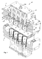
- the hold-down 4 has the function, after closing the pressurized gas thermoforming device by moving together of the upper and lower part of the plastic film or plate 5 firmly on the (overhead) shaping mouth edge of the cavity 3 hold and thereby forming the edge of the plastic container to be produced to impart the desired surface texture.
- the hold-down 4 with respect to the upper part 1 by a short distance of z. B. 1 millimeter axially displaceable and in a corresponding cylindrical recess of a lower housing half 1A of the block-like upper part 1 slidably fitted.
- His function is off FIG. 3 clearly from which it is apparent how the plastic film or sheet is preformed by advancing the forming punch 6 to a container blank 5A, with differences in wall thickness in the deformation region of the plastic film (as usual) set.
- the Formluftverdrlindungsêt 8 is at its (lower in the drawing) end via a screw thread or the like - or possibly also in one piece - firmly connected to the forming die 6.
- end portion of the positive displacement body 8 is fixedly connected to a known support plate 19, which in turn via a coupling pin 19 A with a drive, not shown in the drawing and is movable.
- the upper part 1, or in the embodiment of the upper half of the housing 1B, has large-bore cylinder bores 1C for sealed, slidable guidance of the cylindrical peripheral surfaces 8A of the Formluftverdrfitungsêt 8.
- a further cylinder bore 15C of the still to be described piston plate 15 which is disposed within a cylindrical recess 16 in the upper part 1 and also allows a relation to the ambient atmosphere sealed sliding guide of the mold air displacement body.
- the hold-down 4 is optionally provided with a slightly larger internal cross-section than in the region of its cylinder bore 4C and forms a radial gap 7A between the inner hold-down surface and the cylinder surface 8A.
- the gap width should be between 0.01 and 15 mm, preferably between 1 and 5 mm.
- the cross-sectional area ratios between the inner cross-section of the hold-down 4 and the outer cross-section of the Formluftverdrfitungs stresses 8 between 1: 0.4 and 1: 0.99, and more preferably between 1: 0.8 and 1: 0.99.
- the largest cross-sectional area of the molding die 6 adjoining the lower end of the mold air displacement body 8 may have similar cross-sectional dimensions as the mold air displacement body 8; it can also be dimensioned smaller or larger in dimensions. In this way, when advancing the forming punch 6 only as much under working pressure standing mold air volume must be tracked, as the volume of the gap or Annular space 7B corresponds. It is also possible to choose non-circular cross-sections for the forming die and the positive displacement body 8, if, for example, a non-circular in cross-section, but oval or otherwise oblong shaped plastic container to be produced. In these cases, in which even then the mouth section of the blank holder must be shaped according to the shape of the container mouth edge, the upper part changes accordingly.
- the hold-down 4 can be designed completely backless and therefore from a tubular blank, z. B. by turning, are produced inexpensively.
- the plurality of hold-down piston plate 15 is provided which is movable within a cylindrical recess 16 of the upper part 1, for example pneumatically or hydraulically. As a result, all hold-down 4 can be moved back and forth together to set the plastic film or plate and release it again.
- the piston plate 15 in a cylinder formed in the upper part of the cylinder space (cylindrical recess 16) in radially sealed shape slightly up and down, with a guideway of about 1 mm usually sufficient.
- a perforated closure body 11 to seal the opening of the upper part of the mold air displacement body to the outside sealingly and slidably receive a piston which supports the forming die supporting piston rod.
- the supply of the molding air can be done in different ways.
- the mold air is supplied in a conventional manner by forming air channels within the upper part 1, which open at the receiving the recesses in the upper part. Wall openings 4A of the hold-down device 4 then allow the flow of molding air into the forming gas space 7 formed inside the hold-down device 4.
- FIGS. 6A / B An alternative form gas supply results FIGS. 6A / B, according to which a molding gas distribution assembly is provided, which comprises a multiple mold air displacement body 8 rear summary mold air displacement body support plate 19 and the Formluftverdrnatureungsterrorism 8.
- the Formluftverdrfitungsêt 8 an inner cavity 8B, in the form of air from the support plate 19 flow up and from which the mold air at the lower end, preferably above the forming die 6, can flow out again.
- the Formgasverteilan angel may have individual valves 9, which are provided either in the support plate 19 or on or in the form of air displacement body 8. As a result, the molding gas consumed per production shot and held under pressure can be further reduced in terms of quantity.
- a combined air inlet and outlet pipe 12 may be provided within the cavity 8B serving as a passage for shaping air, which opens freely to the atmosphere at its upper end and for this purpose passes through the support plate 19 can be. It opens with its lower end z. B. in a closure plate 8C of the hollow mold air displacement body 8 and can also have a screw 12E or the like for interchangeable receiving different mold punches 6, moreover.
- An annular sleeve-shaped control slide 9A pushed over the combined inlet / outlet tube 12 is displaceable along the inlet / outlet tube 12 in sealed and slidably guided form by means of a control rod 13 guided through the support plate 19.
- FIG. 6A shown Formlufteinlass ein is the spool 13 in its uppermost working position and thereby at least one lower control bore 12A below the sealing stopper 12C free, so that the molding gas from the cavity 8B of the mold air displacement body 8 via a transverse distribution, for example in the form of a transverse bore 12D from the inlet / Outlet tube 12 can escape.
- This transverse distribution is preferably arranged in the region of the closure plate 8C of the mold air displacement body 8 and opens, preferably, there into an annular channel 8C for the uniform distribution of the shaping gas in all radial directions.
- the spool 9A in its lowest working position, in which it shuts off the lower control bores 12A with respect to the cavity 8B and on the other hand connects the lower control bore 12A with the control bore 12B located above the sealing stopper 12C. In this way, the initially pressurized forming gas can flow back and escape to the atmosphere.
Landscapes
- Engineering & Computer Science (AREA)
- Mechanical Engineering (AREA)
- Moulds For Moulding Plastics Or The Like (AREA)
- Blow-Moulding Or Thermoforming Of Plastics Or The Like (AREA)
Applications Claiming Priority (4)
| Application Number | Priority Date | Filing Date | Title |
|---|---|---|---|
| DE202011001618U DE202011001618U1 (de) | 2011-01-17 | 2011-01-17 | Druckgas-Thermoform-Verbindung |
| DE202011001622U DE202011001622U1 (de) | 2011-01-17 | 2011-01-17 | Druckgas-Thermoform-Vorrichtung |
| DE202011001623U DE202011001623U1 (de) | 2011-01-17 | 2011-01-17 | Druckgas-Thermoform-Vorrichtung |
| DE202011001624U DE202011001624U1 (de) | 2011-01-17 | 2011-01-17 | Druckgas-Thermoform-Vorrichtung |
Publications (2)
| Publication Number | Publication Date |
|---|---|
| EP2476537A2 true EP2476537A2 (fr) | 2012-07-18 |
| EP2476537A3 EP2476537A3 (fr) | 2013-04-24 |
Family
ID=45509255
Family Applications (1)
| Application Number | Title | Priority Date | Filing Date |
|---|---|---|---|
| EP12000246.4A Withdrawn EP2476537A3 (fr) | 2011-01-17 | 2012-01-17 | Dispositif de thermoformage à gaz sous pression |
Country Status (1)
| Country | Link |
|---|---|
| EP (1) | EP2476537A3 (fr) |
Cited By (1)
| Publication number | Priority date | Publication date | Assignee | Title |
|---|---|---|---|---|
| DE102016103237A1 (de) * | 2016-02-24 | 2017-08-24 | Marbach Werkzeugbau Gmbh | Thermoformwerkzeug zur Herstellung becherförmiger Gegenstände |
Citations (5)
| Publication number | Priority date | Publication date | Assignee | Title |
|---|---|---|---|---|
| FR2722135A1 (fr) | 1994-07-11 | 1996-01-12 | Mobile | Dispositif pour realiser par thermoformage des recipients en matiere plastique |
| EP1103365A1 (fr) * | 1999-11-24 | 2001-05-30 | Optipack GmbH & Co. KG | Dispositif pour l'emboutissage de corps en forme de coupes |
| DE10326670B3 (de) | 2003-06-13 | 2004-08-26 | Adolf Illig Maschinenbau Gmbh & Co.Kg | Formwerkzeug zum Tiefziehen von Behältern aus thermoplastischem Kunstoff |
| DE102006020673A1 (de) | 2006-05-04 | 2007-11-08 | Illig Maschinenbau Gmbh & Co. Kg | Verfahren zum Tiefziehen eines Behälters aus einer erwärmten thermoplastischen Kunststofffolie und Formwerkzeug zum Durchführen des Verfahrens |
| DE102007037748B3 (de) | 2007-08-10 | 2008-10-23 | Illig Maschinenbau Gmbh & Co. Kg | Formwerkzeug und Verfahren zum Tiefziehen von Behältern aus einer erwärmten Folienbahn aus thermoplastischem Kunststoff |
Family Cites Families (4)
| Publication number | Priority date | Publication date | Assignee | Title |
|---|---|---|---|---|
| FR1549533A (fr) * | 1967-11-03 | 1968-12-13 | ||
| US5262181A (en) * | 1990-05-14 | 1993-11-16 | Erca Holding | Apparatus for forming hollow articles in thermoplastic material |
| DE29605248U1 (de) * | 1996-03-21 | 1997-07-17 | Gizeh-Werk GmbH, 51702 Bergneustadt | Formwerkzeug |
| EP1361036B1 (fr) * | 2002-05-10 | 2004-05-06 | Adolf Illig Maschinenbau GmbH & Co. KG | Appareil pour l'emboutissage thermoformique ayant un poinçon avec une valve integrée |
-
2012
- 2012-01-17 EP EP12000246.4A patent/EP2476537A3/fr not_active Withdrawn
Patent Citations (5)
| Publication number | Priority date | Publication date | Assignee | Title |
|---|---|---|---|---|
| FR2722135A1 (fr) | 1994-07-11 | 1996-01-12 | Mobile | Dispositif pour realiser par thermoformage des recipients en matiere plastique |
| EP1103365A1 (fr) * | 1999-11-24 | 2001-05-30 | Optipack GmbH & Co. KG | Dispositif pour l'emboutissage de corps en forme de coupes |
| DE10326670B3 (de) | 2003-06-13 | 2004-08-26 | Adolf Illig Maschinenbau Gmbh & Co.Kg | Formwerkzeug zum Tiefziehen von Behältern aus thermoplastischem Kunstoff |
| DE102006020673A1 (de) | 2006-05-04 | 2007-11-08 | Illig Maschinenbau Gmbh & Co. Kg | Verfahren zum Tiefziehen eines Behälters aus einer erwärmten thermoplastischen Kunststofffolie und Formwerkzeug zum Durchführen des Verfahrens |
| DE102007037748B3 (de) | 2007-08-10 | 2008-10-23 | Illig Maschinenbau Gmbh & Co. Kg | Formwerkzeug und Verfahren zum Tiefziehen von Behältern aus einer erwärmten Folienbahn aus thermoplastischem Kunststoff |
Cited By (2)
| Publication number | Priority date | Publication date | Assignee | Title |
|---|---|---|---|---|
| DE102016103237A1 (de) * | 2016-02-24 | 2017-08-24 | Marbach Werkzeugbau Gmbh | Thermoformwerkzeug zur Herstellung becherförmiger Gegenstände |
| DE102016103237B4 (de) | 2016-02-24 | 2020-01-23 | Marbach Werkzeugbau Gmbh | Thermoformwerkzeug zur Herstellung becherförmiger Gegenstände |
Also Published As
| Publication number | Publication date |
|---|---|
| EP2476537A3 (fr) | 2013-04-24 |
Similar Documents
| Publication | Publication Date | Title |
|---|---|---|
| DE69010429T2 (de) | Vorrichtung und Verfahren zum Formen eines rohrförmigen Rahmens. | |
| DE2256945A1 (de) | Verfahren und vorrichtung zum blasformen von kunststoffgegenstaenden | |
| DE19622372B4 (de) | Verfahren und Vorrichtung zum Herstellen von Nockenwellen | |
| DE1291469C2 (de) | Verfahren und Vorrichtung zum Herstellen eines duennwandigen, oben offenen Behaelters aus einer Folie aus thermoplastischem Kunststoff | |
| DE2415549B2 (de) | Vorrichtung für die spanlose Kaltverformung eines Rohlings | |
| DE10043209A1 (de) | Flexibles Werkzeug zur Umformung eines Werkstücks | |
| DE1299854B (de) | Ziehverfahren fuer plattenfoermige Rohlinge aus einem druckplastifizierbaren Feststoff und Einrichtung zur Durchfuehrung des Verfahrens | |
| DE60106812T2 (de) | Verfahren zum Herstellen von metallischen Faltenbälgen | |
| DE19842750A1 (de) | Verfahren und Herstellung von tiefgezogenen Hohlteilen und Ziehwerkzeug | |
| DE2033106A1 (de) | Stauch oder Schmiedepresse | |
| DE3024683A1 (de) | Kunststoffbecher sowie verfahren und tiefziehwerkzeug zu seiner herstellung | |
| DE102013216863B4 (de) | Werkzeugsystem und Verfahren zur Herstellung von Bauteilen nach dem RTM-Verfahren | |
| DE102007037748B3 (de) | Formwerkzeug und Verfahren zum Tiefziehen von Behältern aus einer erwärmten Folienbahn aus thermoplastischem Kunststoff | |
| EP0682999B1 (fr) | Article moulé, procédé et installation pour sa préparation | |
| DE1479245A1 (de) | Verfahren zur Fabrikation von duennwandigen Behaeltern aus thermoplastischem Material und Einrichtung zu seiner Verwirklichung | |
| EP1764173B1 (fr) | Dispositif pour mouler de la poudre par pression | |
| DE202011001623U1 (de) | Druckgas-Thermoform-Vorrichtung | |
| DE9411461U1 (de) | Vorrichtung zum Hochdruckformen von Felgenkränzen | |
| DE1429050C3 (de) | Verfahren und Vorrichtung zum Herstel len eines dünnwandigen, einseitig offenen Gefäßes, insbesondere emes Bechers, aus thermoplastischem Kunststoff | |
| DE1452547B2 (de) | Hydraulische Druckregelungseinrichtung an einer Vorrichtung zur Herstellung eines verzweigten Rohranschlusses | |
| DE202011001618U1 (de) | Druckgas-Thermoform-Verbindung | |
| DE102004012439B4 (de) | Verfahren zum Tiefziehen und Ausstanzen von Behältern aus einer thermoplastischen Kunststofffolie und Vorrichtung zum Tiefziehen und Ausstanzen von Behältern | |
| DE1299855B (de) | Ziehverfahren fuer plattenartige Rohlinge aus einem druckplastifizierbaren Feststoff | |
| DE2400828A1 (de) | Tiefziehwerkzeug fuer das tiefziehen im weiterschlag | |
| DE202011001622U1 (de) | Druckgas-Thermoform-Vorrichtung |
Legal Events
| Date | Code | Title | Description |
|---|---|---|---|
| PUAI | Public reference made under article 153(3) epc to a published international application that has entered the european phase |
Free format text: ORIGINAL CODE: 0009012 |
|
| AK | Designated contracting states |
Kind code of ref document: A2 Designated state(s): AL AT BE BG CH CY CZ DE DK EE ES FI FR GB GR HR HU IE IS IT LI LT LU LV MC MK MT NL NO PL PT RO RS SE SI SK SM TR |
|
| AX | Request for extension of the european patent |
Extension state: BA ME |
|
| RIC1 | Information provided on ipc code assigned before grant |
Ipc: B29C 51/04 20060101AFI20121128BHEP |
|
| PUAL | Search report despatched |
Free format text: ORIGINAL CODE: 0009013 |
|
| AK | Designated contracting states |
Kind code of ref document: A3 Designated state(s): AL AT BE BG CH CY CZ DE DK EE ES FI FR GB GR HR HU IE IS IT LI LT LU LV MC MK MT NL NO PL PT RO RS SE SI SK SM TR |
|
| AX | Request for extension of the european patent |
Extension state: BA ME |
|
| RIC1 | Information provided on ipc code assigned before grant |
Ipc: B29C 47/04 20060101AFI20130318BHEP Ipc: B29C 51/26 20060101ALI20130318BHEP |
|
| 17P | Request for examination filed |
Effective date: 20131024 |
|
| RBV | Designated contracting states (corrected) |
Designated state(s): AL AT BE BG CH CY CZ DE DK EE ES FI FR GB GR HR HU IE IS IT LI LT LU LV MC MK MT NL NO PL PT RO RS SE SI SK SM TR |
|
| 17Q | First examination report despatched |
Effective date: 20141021 |
|
| STAA | Information on the status of an ep patent application or granted ep patent |
Free format text: STATUS: EXAMINATION IS IN PROGRESS |
|
| STAA | Information on the status of an ep patent application or granted ep patent |
Free format text: STATUS: THE APPLICATION IS DEEMED TO BE WITHDRAWN |
|
| 18D | Application deemed to be withdrawn |
Effective date: 20170530 |