EP2476586B1 - Verfahren zur herstellung von klängen für abbiegesignaltöne in einem automobil sowie klangerzeuger für abbiegesignaltöne in einem automobil - Google Patents
Verfahren zur herstellung von klängen für abbiegesignaltöne in einem automobil sowie klangerzeuger für abbiegesignaltöne in einem automobil Download PDFInfo
- Publication number
- EP2476586B1 EP2476586B1 EP10813637.5A EP10813637A EP2476586B1 EP 2476586 B1 EP2476586 B1 EP 2476586B1 EP 10813637 A EP10813637 A EP 10813637A EP 2476586 B1 EP2476586 B1 EP 2476586B1
- Authority
- EP
- European Patent Office
- Prior art keywords
- signal
- sound
- turn
- frequency
- pulse
- Prior art date
- Legal status (The legal status is an assumption and is not a legal conclusion. Google has not performed a legal analysis and makes no representation as to the accuracy of the status listed.)
- Active
Links
Images




Classifications
-
- B—PERFORMING OPERATIONS; TRANSPORTING
- B60—VEHICLES IN GENERAL
- B60Q—ARRANGEMENT OF SIGNALLING OR LIGHTING DEVICES, THE MOUNTING OR SUPPORTING THEREOF OR CIRCUITS THEREFOR, FOR VEHICLES IN GENERAL
- B60Q5/00—Arrangement or adaptation of acoustic signal devices
- B60Q5/005—Arrangement or adaptation of acoustic signal devices automatically actuated
-
- B—PERFORMING OPERATIONS; TRANSPORTING
- B60—VEHICLES IN GENERAL
- B60Q—ARRANGEMENT OF SIGNALLING OR LIGHTING DEVICES, THE MOUNTING OR SUPPORTING THEREOF OR CIRCUITS THEREFOR, FOR VEHICLES IN GENERAL
- B60Q1/00—Arrangement of optical signalling or lighting devices, the mounting or supporting thereof or circuits therefor
- B60Q1/26—Arrangement of optical signalling or lighting devices, the mounting or supporting thereof or circuits therefor the devices being primarily intended to indicate the vehicle, or parts thereof, or to give signals, to other traffic
- B60Q1/34—Arrangement of optical signalling or lighting devices, the mounting or supporting thereof or circuits therefor the devices being primarily intended to indicate the vehicle, or parts thereof, or to give signals, to other traffic for indicating change of drive direction
Definitions
- the present invention relates to a method for generating turn-signal sound of a vehicle and a device for generating turn-signal sound of a vehicle.
- turn-signal sound of a vehicle utilized an operating sound generated by an activated mechanical relay for flashing a turn-signal lamp.
- a semiconductor switch for the turn-signal lamp instead of the mechanical relay.
- the turn-signal sound cannot be generated from the semiconductor switch and thus there is a proposal of generating the turn-signal sound by outputting a pulse signal from a sound generator port (hereinafter called an S/G port) of a central processing unit (CPU), converting the pulse signal into an analog signal using an integration circuit, and providing the analog signal to a speaker or a piezoelectric buzzer or the like which is intermittently activated to produce the turn-signal sound.
- a sound generator port hereinafter called an S/G port
- CPU central processing unit
- the above-described CPU is also used to generate an alarm sound from the above-described speaker and the piezoelectric buzzer when an alarm is activated, by outputting the pulse signal to the above-described speaker and the piezoelectric buzzer.
- the respective sounds are arranged according to a priority order so that when an event occurs which requires generating the sound with a higher priority order while generating the sound with a lower priority order, the sound with the lower priority order is cancelled in order to generate the sound with the higher priority order.
- both of the turn-signal sound and the alarm sound can be produced using the single device, however, the sound with the lower priority order is cancelled when producing both sounds at the same time. As a result, the user may feel uncomfortable.
- a method for generating an informing sound in a vehicle is also known from US 2003/227376 (A1 ).
- a PCM sound generator and a D/A converter is employed for generating an informing sound with a characteristic that varies over time. For example, when a right turn is instructed, an informing sound is generated with a characteristic to progressively raise the sound pitch from a relatively low sound pitch, while when a left turn is instructed, an informing sound is generated with a characteristic to progressively lower the sound pitch from a relatively low sound pitch, or vice versa.
- Reference WO 2009/019945 (A1 ) relates a light source turn-on/off controller and discloses a low-pass filter for converting a PWM signal into an analog signal.
- a sound signal generator with a mixer for mixing a turn signal sound and various other kinds of alarm sounds in a vehicle is also disclosed in JP 2007/112347 (A ).
- an object of the present invention is to provide a method for generating turn-signal sound of a vehicle which can satisfy the user's demand for the tone of the turn-signal sound at low cost.
- Another object of the present invention is to provide a device for generating turn-signal sound of a vehicle.
- the pulse signal for turn-signal sound is integrated and outputted to the speaker.
- the frequency of the sound outputted from the speaker can be determined according to the pulse signal for turn-signal sound
- the sound-volume of the sound outputted from the speaker can be determined according to the duty ratio of the pulse signal for turn-signal sound.
- the speaker can output the sound having the varying frequency and sound-volume.
- the tone of the turn-signal sound outputted from the speaker can be adjusted by adjusting the frequency and the duty ratio of the pulse signal for turn-signal sound, thereby satisfying the user's particular demand regarding to the tone of the turn-signal sound. Furthermore, since the pulse signal for turn-signal sound is integrated and outputted to the speaker, a D/A converter for decoding is not required, thus the cost can be reduced. Therefore, the user's demand for the tone of the turn-signal sound can be satisfied without increasing the cost.
- the analog signal for turn-signal sound and the analog signal for alarm sound are summed up and the summed signal is outputted to the speaker.
- the turn-signal sound and the alarm sound can be outputted simultaneously from a single speaker.
- the frequency and the duty ratio of the pulse signal for turn-signal sound are varying according to the frequency and the sound pressure corresponding to the frequency included in the operating sound of the mechanical relay.
- the speaker can output the turn-signal sound close to the operating sound of the mechanical relay, thus the user's demand for the tone of the turn-signal sound can be satisfied.
- a sound-generating device 1 for generating turn-signal sound of a vehicle includes a CPU (central processing unit) 2, a plurality of integration circuits 31-34, a summation circuit 4, a speaker 5 and a voltage-dividing resistor R.
- the CPU 2 includes a PPG (pulse pattern generator) port 21 for outputting a pulse signal for the turn-signal sound and S/G (sound generator) ports 22-24.
- the PPG port 21 burdens the CPU 2, the PPG port 21can determine a high-level period and a low-level period of the pulse individually, thus the frequency and the duty ratio of the pulse can be controlled in detail.
- This PPG port 21 intermittently outputs (e.g. outputs every 5.2 kHz) the pulse signal for turn-signal sound having fast-varying frequency and duty ratio, as shown in Fig. 2A .
- the frequency and the duty ratio of the pulse cannot be controlled by the S/G ports 22-24 although they do not put much load on the CPU 2.
- Each of the S/G ports 22-24 intermittently outputs the pulse signal for alarm sound having the constant frequency and the constant duty ratio (e.g. the frequency of 700Hz and the duty ratio of 50%), as shown in Fig. 3A .
- the integration circuit 31-34 described above is a well-known CR filter constituted of a capacitor and a resistor.
- the above-described integration circuit 31 integrates the above-described pulse signal for turn-signal sound to convert the pulse signal for turn-signal sound into an analog signal for turn-signal sound.
- the frequency of this analog signal for turn-signal sound is determined by the frequency of the pulse signal for turn-signal sound.
- the amplitude of the analog signal for turn-signal sound is determined by the duty ratio of the pulse signal for turn-signal sound.
- the integration circuit 32-34 described above is arranged to integrate the pulse signal for alarm sound which is outputted from the S/G port 22-24 to convert the pulse signal for alarm sound into the analog signal for alarm sound.
- the pulse signal having the constant frequency and the constant duty ratio there is obtained the analog signal for alarm sound having the constant frequency and the constant amplitude, as shown in Fig. 3B .
- the summation circuit 4 described above is a well-known summation circuit which is arranged to sum up the plurality of analog signals inputted to the summation circuit 4.
- the summation circuit 4 sums up the analog signal for turn-signal sound and the analog signal for alarm sound which were outputted from the integration circuits 31-34, and then outputs a summed signal to the speaker 5.
- Each of the voltage-dividing resistors R described above is arranged between the respective integration circuits 31-34 and the summation circuit 4.
- the voltage-dividing resistor R divides a voltage of the analog signal for turn-signal sound and the analog signal for alarm sound which are outputted from the integration circuits 31-34, respectively, which are then outputted to the summation circuit 4.
- the voltage-dividing resistor R By adjusting the voltage-dividing resistor R, the magnitude of the analog signal for turn-signal sound and the analog signal for alarm sound can be adjusted before being provided to the summation circuit 4.
- the voltage-dividing resistor R is adjusted so that the magnitude of the analog signal for turn-signal sound is larger than the magnitude of the analog signal for alarm sound.
- the CPU 2 When a turn-signal switch not shown is turned on, the CPU 2 outputs from the PPG port 21 the pulse signal for turn-signal sound having the fast-varying frequency and duty ratio. Then, the pulse signal for turn-signal sound is provided to the integration circuit 31, in which the pulse signal for turn-signal sound is integrated and converted into the analog signal for turn-signal sound.
- the frequency of the analog signal for turn-signal sound is determined by the frequency of the pulse signal for turn-signal sound
- the amplitude of the analog signal for turn-signal sound is determined by the duty ratio of the pulse signal for turn-signal sound.
- the voltage of the obtained analog signal for turn-signal sound is divided by the voltage-dividing resistor R, and then the analog signal for turn-signal sound is provided to the summation circuit 4. If there is no analog signal for alarm sound provided from the integration circuits 32-34, then the summation circuit 4 outputs the analog signal for turn-signal sound to the speaker 5. Then, when the analog signal for turn-signal sound is inputted to the speaker 5, the speaker 5 intermittently outputs a sound having the fast-varying frequency and sound-volume corresponding to the analog signal for turn-signal sound. Due to a characteristic property of a human ear, when a person hears the sound having the fast-varying frequency, the person recognizes as if the sound with a plurality of frequencies are heard simultaneously.
- the tone of the turn-signal sound can be adjusted.
- the turn-signal sound close to the operating sound of the mechanical relay can be outputted from the speaker 5, so the user's demand for the tone of the turn-signal sound can be satisfied.
- the pulse signal for alarm sound having the constant frequency and the constant duty ratio is intermittently outputted from the S/G port 22-24 by the CPU 2, as shown in Fig. 3A , and provided to the integration circuit 32-34.
- the pulse signal for alarm sound is then integrated by the integration circuit 32-34 and converted into the analog signal for alarm sound.
- the analog signal for alarm sound having the constant frequency and the constant amplitude as shown in Fig. 3B .
- the voltage of the obtained analog signal for alarm sound is divided by the voltage-dividing resistor R, and then the analog signal for alarm sound is provided to the summation circuit 4. If there is no analog signal for turn-signal sound outputted from the integration circuit 31, and if there is no more than one analog signal for alarm sound outputted from the integration circuit 32-34, then the summation circuit 4 outputs the analog signal for alarm sound to the speaker 5. Then, when the analog signal for alarm sound is inputted to the speaker 5 and the speaker 5 intermittently outputs sound having the constant frequency and the constant sound-volume according to the analog signal for alarm sound.
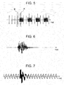
- the summation circuit 4 sums up the analog signal for turn-signal sound and the analog signal for alarm sound, as shown in Fig. 5 .
- the resulting summed signal is constituted of the analog signal for turn-signal sound having the fast-varying frequency and amplitude, which is shown in Fig. 6 , superposed on the analog signal for alarm sound having the constant frequency and the constant amplitude.
- the summed signal has a wave shape as shown in Fig. 7 .
- the summation circuit 4 outputs the summed signal to the speaker 5. In such manner, the turn-signal sound and the alarm sound can be outputted simultaneously from the speaker 5.
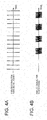
- Fig. 8 shows a result of the frequency analysis on the turn-signal sound of the mechanical relay.
- the turn-signal sound of the mechanical relay is widely distributed across the audible region. Therefore, by determining the frequency and the duty ratio of the pulse signal for turn-signal sound so as to vary according to the frequency and the sound pressure corresponding to the frequency included in the operating sound of the mechanical relay (i.e. to vary fast within 100Hz to 10000Hz), the speaker 5 can output the turn-signal sound close to the operating sound of the mechanical relay.
- the pulse signal for turn-signal sound it is not easy to adjust the pulse signal for turn-signal sound to vary across the wide audible region in a short period of time for producing the turn-signal sound.
- the frequency components which are out of the frequency range of the speaker 5 e.g. the frequency components equal or smaller than 500Hz
- the frequency components corresponding to the odd multiple of the corresponding frequency are also eliminated.
- a frequency analysis is conducted on the turn-signal sound of the mechanical relay having the frequency property as shown in Fig. 8 , by eliminating the odd multiple frequency components while leaving only the fundamental frequency, and subjecting to a dynamic control process using a noise gate or a compressor.
- the result of the analysis shown in Fig. 9 shows that, before processing, the frequency components are widely distributed across the audible region, whereas after the processing, only the specific frequency components are distributed forming peaks.
- the pulse signal for turn-signal sound to vary according to the frequency peaks, the odd multiple frequency components of the corresponding frequency can be eliminated.
- the frequency components which are out of the frequency range of the speaker 5 are eliminated from the pulse signal for turn-signal sound.
- the time for outputting the pulse signal for turn-signal sound with the frequency components which cannot be produced by the speaker 5 can be eliminated, thus the time can be used efficiently for outputting the pulse signal for turn-signal sound having the frequency components which can be produced by the speaker 5.
- high-quality turn-signal sound can be produced.
- the pulse signal contains the odd harmonics
- the odd multiple frequency components of the corresponding frequency are eliminated from the pulse signal for turn-signal sound.
- the time for outputting the unnecessary pulse signal for turn-signal sound can be eliminated, thus the time can be used efficiently for outputting the efficient pulse signal for turn-signal sound.
- high-quality turn-signal sound can be produced.
- the analog signal for turn-signal sound and the analog signal for alarm sound are summed together to simultaneously output the turn-signal sound and the alarm sound from the speaker 5.
- the present invention is not limited to this regard, and for example, two speakers may be used to output the turn-signal sound and the alarm sound separately.
- the frequency distribution varies across the audible region.
- the present invention is not limited to this regard, and the frequency distribution may vary according to the user's demand.
Landscapes
- Engineering & Computer Science (AREA)
- Mechanical Engineering (AREA)
- Physics & Mathematics (AREA)
- Acoustics & Sound (AREA)
- Fittings On The Vehicle Exterior For Carrying Loads, And Devices For Holding Or Mounting Articles (AREA)
- Circuit For Audible Band Transducer (AREA)
Claims (4)
- Verfahren zum Erzeugen eines Abbiegesignal-Tons eines Fahrzeugs, das die folgenden Schritte umfasst:Ausgeben eines Impulssignals für einen Abbiegesignal-Ton über einen Impulsmuster-Generator (21), wobei das Impulssignal für einen Abbiegesignal-Ton variierende Frequenz und variierendes Tastverhältnis hat;Umwandeln des Impulssignals für einen Abbiegesignal-Ton in ein analoges Signal für einen Abbiegesignal-Ton durch Integrieren des Impulssignals für einen Abbiegesignal-Ton; undAusgeben des analogen Signals für einen Abbiegesignal-Ton an einen Lautsprecher (5).
- Verfahren nach Anspruch 1, das des Weiteren die folgenden Schritte umfasst:Ausgeben eines Impulssignals für einen Warnton von einer Tonerzeugungseinrichtung (22), wobei das Impulssignal für einen Warnton die konstante Frequenz und das konstante Tastverhältnis hat;Umwandeln des Impulssignals für einen Warnton in ein analoges Signal für einen Warnton durch Integrieren des Impulssignals für einen Warnton;Summieren des analogen Signals für einen Abbiegesignal-Ton und des analogen Signals für einen Warnton; sowieAusgeben des summierten Signals anstelle des analogen Signals für einen Abbiegesignal-Ton an den Lautsprecher (5).
- Verfahren nach Anspruch 1 oder 2, wobei die Frequenz und das Tastverhältnis des Impulssignals für einen von dem Impulsmuster-Generator (21) ausgegebenen Abbiegesignal-Ton so eingerichtet sind, dass sie je nach der Frequenz und dem Schalldruck variieren, die der Frequenz entsprechen, die in einem Betriebsgeräusch eines mechanischen Relais enthalten ist.
- Vorrichtung (1), die so ausgeführt ist, dass sie einen Abbiegesignal-Ton eines Fahrzeugs erzeugt, wobei sie umfasst:eine zentrale Verarbeitungseinheit (2), die so ausgeführt ist, dass sie über einen Impulsmuster-Generator (21) ein Impulssignal für einen Abbiegesignal-Ton mit variierender Frequenz und variierendem Tastverhältnis ausgibt;eine Integrations-Einheit (31), die so ausgeführt ist, dass sie das Impulssignal für einen Abbiegesignal-Ton integriert, um das Impulssignal für einen Abbiegesignal-Ton in ein analoges Signal für einen Abbiegesignal-Ton umzuwandeln; undeinen Lautsprecher (5), an den das analoge Signal für einen Abbiegesignal-Ton ausgegeben wird.
Applications Claiming Priority (2)
| Application Number | Priority Date | Filing Date | Title |
|---|---|---|---|
| JP2009205209A JP5325053B2 (ja) | 2009-09-04 | 2009-09-04 | 自動車用ターン音の吹鳴方法及び自動車用ターン音の吹鳴装置 |
| PCT/JP2010/064343 WO2011027688A1 (ja) | 2009-09-04 | 2010-08-25 | 自動車用ターン音の吹鳴方法及び自動車用ターン音の吹鳴装置 |
Publications (3)
| Publication Number | Publication Date |
|---|---|
| EP2476586A1 EP2476586A1 (de) | 2012-07-18 |
| EP2476586A4 EP2476586A4 (de) | 2016-11-30 |
| EP2476586B1 true EP2476586B1 (de) | 2020-04-15 |
Family
ID=43649227
Family Applications (1)
| Application Number | Title | Priority Date | Filing Date |
|---|---|---|---|
| EP10813637.5A Active EP2476586B1 (de) | 2009-09-04 | 2010-08-25 | Verfahren zur herstellung von klängen für abbiegesignaltöne in einem automobil sowie klangerzeuger für abbiegesignaltöne in einem automobil |
Country Status (5)
| Country | Link |
|---|---|
| US (1) | US8638208B2 (de) |
| EP (1) | EP2476586B1 (de) |
| JP (1) | JP5325053B2 (de) |
| CN (1) | CN102448772B (de) |
| WO (1) | WO2011027688A1 (de) |
Families Citing this family (10)
| Publication number | Priority date | Publication date | Assignee | Title |
|---|---|---|---|---|
| JP5746583B2 (ja) * | 2011-08-01 | 2015-07-08 | 矢崎総業株式会社 | 作動音生成装置 |
| JP5699920B2 (ja) * | 2011-12-05 | 2015-04-15 | 株式会社デンソー | 車両用音響装置 |
| JP5974369B2 (ja) * | 2012-12-26 | 2016-08-23 | カルソニックカンセイ株式会社 | ブザー出力制御装置およびブザー出力制御方法 |
| JP6111955B2 (ja) * | 2013-09-27 | 2017-04-12 | アンデン株式会社 | 車両接近通報装置 |
| US9204521B2 (en) * | 2014-01-22 | 2015-12-01 | Tavi Salomon | Adapting turn signal |
| US10305578B2 (en) | 2014-05-14 | 2019-05-28 | Satixfy Israel Ltd. | Method of exchanging communications between a satellite and terminals associated therewith |
| US10368327B2 (en) | 2014-05-14 | 2019-07-30 | Satixfy Israel Ltd. | Method and system for signal communications |
| KR101668610B1 (ko) * | 2015-12-03 | 2016-10-24 | 주식회사 원더풀플랫폼 | 차량의 방향지시등 동작음 제어 시스템 |
| CN111775828B (zh) * | 2020-07-15 | 2026-01-02 | 杭叉集团股份有限公司 | 一种车辆、转向警示装置、控制方法 |
| KR20250173771A (ko) * | 2024-06-04 | 2025-12-11 | 박남숙 | 차량용 방향지시등 알림음 제어 시스템 |
Family Cites Families (12)
| Publication number | Priority date | Publication date | Assignee | Title |
|---|---|---|---|---|
| CN2060129U (zh) * | 1989-12-27 | 1990-08-08 | 宝忠会 | 车用转向灯可调式电子讯响闪烁器 |
| CN2196054Y (zh) * | 1994-03-07 | 1995-05-03 | 傅亚文 | 机动车语音报值、警告和提示装置 |
| JPH0922289A (ja) * | 1995-07-04 | 1997-01-21 | Uniden Corp | 発音体の駆動方法及び駆動装置 |
| JPH09301068A (ja) * | 1996-05-13 | 1997-11-25 | Niles Parts Co Ltd | 電子フラッシャ装置 |
| JPH10214090A (ja) * | 1997-01-31 | 1998-08-11 | Kansei Corp | ブザー駆動回路 |
| US5986540A (en) * | 1997-09-18 | 1999-11-16 | Nakagaki; Koutaro | Sound signal generating device |
| TW469689B (en) * | 1998-11-04 | 2001-12-21 | Rohm Co Ltd | Audio amplifier circuit and audio device using the circuit |
| CN2736213Y (zh) * | 2002-05-27 | 2005-10-26 | 雅马哈株式会社 | 能够听觉地通知其状态的车辆 |
| JP3876767B2 (ja) * | 2002-06-06 | 2007-02-07 | ヤマハ株式会社 | 報知音発生方法および装置、並びに報知音発生プログラム |
| JP4577615B2 (ja) * | 2005-10-21 | 2010-11-10 | 日本精機株式会社 | 車両用情報提供装置 |
| CN1986285B (zh) * | 2006-12-22 | 2010-04-07 | 哈尔滨工业大学 | 汽车电子转向警示声响闪光器 |
| CN101772438B (zh) * | 2007-08-07 | 2012-10-24 | 罗姆股份有限公司 | 光源的点亮或熄灭控制装置 |
-
2009
- 2009-09-04 JP JP2009205209A patent/JP5325053B2/ja not_active Expired - Fee Related
-
2010
- 2010-08-25 CN CN201080023465.9A patent/CN102448772B/zh active Active
- 2010-08-25 EP EP10813637.5A patent/EP2476586B1/de active Active
- 2010-08-25 US US13/379,190 patent/US8638208B2/en not_active Expired - Fee Related
- 2010-08-25 WO PCT/JP2010/064343 patent/WO2011027688A1/ja not_active Ceased
Non-Patent Citations (1)
| Title |
|---|
| None * |
Also Published As
| Publication number | Publication date |
|---|---|
| EP2476586A4 (de) | 2016-11-30 |
| CN102448772B (zh) | 2015-04-29 |
| US20120098656A1 (en) | 2012-04-26 |
| EP2476586A1 (de) | 2012-07-18 |
| JP5325053B2 (ja) | 2013-10-23 |
| US8638208B2 (en) | 2014-01-28 |
| CN102448772A (zh) | 2012-05-09 |
| JP2011056967A (ja) | 2011-03-24 |
| WO2011027688A1 (ja) | 2011-03-10 |
Similar Documents
| Publication | Publication Date | Title |
|---|---|---|
| US8638208B2 (en) | Method for generating turn-signal sound of vehicle and device using the same | |
| US9580010B2 (en) | Vehicle approach notification apparatus | |
| CN107533839B (zh) | 一种对周围环境音的处理方法及设备 | |
| US9832570B2 (en) | Special sound producing device | |
| JP2015027828A (ja) | 車両接近通報装置 | |
| EP0977463A3 (de) | Verarbeitungssystem zur Schallbildlocalisierung von Audiosignalen für linkes und rechtes Ohr | |
| JP6510241B2 (ja) | 警報装置 | |
| JP4440333B1 (ja) | 補聴器 | |
| JP4977066B2 (ja) | 車両用音声案内装置 | |
| JP5071793B2 (ja) | 車両用情報提供装置 | |
| CN113518734A (zh) | 语音输出装置 | |
| JP6007894B2 (ja) | サイレン音出力装置 | |
| KR100558854B1 (ko) | 청각장애가 있는 운전자를 위한 경음기 인지방법 | |
| JP2009260544A (ja) | 車両用警報駆動装置 | |
| AU2017395531B2 (en) | Vehicle alarm generation device | |
| US20070146123A1 (en) | Multi-tone back-up alarm | |
| JP2008001124A (ja) | 車載用発音装置 | |
| JP7685149B2 (ja) | 車両用発音体制御装置 | |
| JP2007269044A (ja) | 車載用発音装置 | |
| JPH04338420A (ja) | 電気調理器の報知装置 | |
| JP6510242B2 (ja) | 効果音吹鳴装置 | |
| KR20100005997U (ko) | 백색소음 출력장치 | |
| JP2016109705A (ja) | 和音用デジタル信号の生成方法および生成装置 | |
| Baldwin | Auditory perception. | |
| KR20060030738A (ko) | 다중 채널 음향 시스템의 알파파 발생 장치 |
Legal Events
| Date | Code | Title | Description |
|---|---|---|---|
| PUAI | Public reference made under article 153(3) epc to a published international application that has entered the european phase |
Free format text: ORIGINAL CODE: 0009012 |
|
| 17P | Request for examination filed |
Effective date: 20111017 |
|
| AK | Designated contracting states |
Kind code of ref document: A1 Designated state(s): AL AT BE BG CH CY CZ DE DK EE ES FI FR GB GR HR HU IE IS IT LI LT LU LV MC MK MT NL NO PL PT RO SE SI SK SM TR |
|
| DAX | Request for extension of the european patent (deleted) | ||
| RA4 | Supplementary search report drawn up and despatched (corrected) |
Effective date: 20161027 |
|
| RIC1 | Information provided on ipc code assigned before grant |
Ipc: B60Q 5/00 20060101AFI20161021BHEP Ipc: G10K 9/18 20060101ALI20161021BHEP Ipc: B60Q 1/34 20060101ALI20161021BHEP Ipc: B60R 16/02 20060101ALI20161021BHEP |
|
| STAA | Information on the status of an ep patent application or granted ep patent |
Free format text: STATUS: EXAMINATION IS IN PROGRESS |
|
| 17Q | First examination report despatched |
Effective date: 20180606 |
|
| GRAP | Despatch of communication of intention to grant a patent |
Free format text: ORIGINAL CODE: EPIDOSNIGR1 |
|
| STAA | Information on the status of an ep patent application or granted ep patent |
Free format text: STATUS: GRANT OF PATENT IS INTENDED |
|
| INTG | Intention to grant announced |
Effective date: 20191212 |
|
| RIN1 | Information on inventor provided before grant (corrected) |
Inventor name: IKEDA, NAOHISA |
|
| GRAS | Grant fee paid |
Free format text: ORIGINAL CODE: EPIDOSNIGR3 |
|
| GRAA | (expected) grant |
Free format text: ORIGINAL CODE: 0009210 |
|
| STAA | Information on the status of an ep patent application or granted ep patent |
Free format text: STATUS: THE PATENT HAS BEEN GRANTED |
|
| RIN1 | Information on inventor provided before grant (corrected) |
Inventor name: IKEDA, NAOHISA |
|
| AK | Designated contracting states |
Kind code of ref document: B1 Designated state(s): AL AT BE BG CH CY CZ DE DK EE ES FI FR GB GR HR HU IE IS IT LI LT LU LV MC MK MT NL NO PL PT RO SE SI SK SM TR |
|
| REG | Reference to a national code |
Ref country code: CH Ref legal event code: EP Ref country code: GB Ref legal event code: FG4D |
|
| REG | Reference to a national code |
Ref country code: DE Ref legal event code: R096 Ref document number: 602010063942 Country of ref document: DE |
|
| REG | Reference to a national code |
Ref country code: IE Ref legal event code: FG4D |
|
| REG | Reference to a national code |
Ref country code: AT Ref legal event code: REF Ref document number: 1256898 Country of ref document: AT Kind code of ref document: T Effective date: 20200515 |
|
| REG | Reference to a national code |
Ref country code: NL Ref legal event code: MP Effective date: 20200415 |
|
| REG | Reference to a national code |
Ref country code: LT Ref legal event code: MG4D |
|
| PG25 | Lapsed in a contracting state [announced via postgrant information from national office to epo] |
Ref country code: IS Free format text: LAPSE BECAUSE OF FAILURE TO SUBMIT A TRANSLATION OF THE DESCRIPTION OR TO PAY THE FEE WITHIN THE PRESCRIBED TIME-LIMIT Effective date: 20200815 Ref country code: SE Free format text: LAPSE BECAUSE OF FAILURE TO SUBMIT A TRANSLATION OF THE DESCRIPTION OR TO PAY THE FEE WITHIN THE PRESCRIBED TIME-LIMIT Effective date: 20200415 Ref country code: NO Free format text: LAPSE BECAUSE OF FAILURE TO SUBMIT A TRANSLATION OF THE DESCRIPTION OR TO PAY THE FEE WITHIN THE PRESCRIBED TIME-LIMIT Effective date: 20200715 Ref country code: GR Free format text: LAPSE BECAUSE OF FAILURE TO SUBMIT A TRANSLATION OF THE DESCRIPTION OR TO PAY THE FEE WITHIN THE PRESCRIBED TIME-LIMIT Effective date: 20200716 Ref country code: PT Free format text: LAPSE BECAUSE OF FAILURE TO SUBMIT A TRANSLATION OF THE DESCRIPTION OR TO PAY THE FEE WITHIN THE PRESCRIBED TIME-LIMIT Effective date: 20200817 Ref country code: LT Free format text: LAPSE BECAUSE OF FAILURE TO SUBMIT A TRANSLATION OF THE DESCRIPTION OR TO PAY THE FEE WITHIN THE PRESCRIBED TIME-LIMIT Effective date: 20200415 Ref country code: FI Free format text: LAPSE BECAUSE OF FAILURE TO SUBMIT A TRANSLATION OF THE DESCRIPTION OR TO PAY THE FEE WITHIN THE PRESCRIBED TIME-LIMIT Effective date: 20200415 Ref country code: NL Free format text: LAPSE BECAUSE OF FAILURE TO SUBMIT A TRANSLATION OF THE DESCRIPTION OR TO PAY THE FEE WITHIN THE PRESCRIBED TIME-LIMIT Effective date: 20200415 |
|
| REG | Reference to a national code |
Ref country code: AT Ref legal event code: MK05 Ref document number: 1256898 Country of ref document: AT Kind code of ref document: T Effective date: 20200415 |
|
| PG25 | Lapsed in a contracting state [announced via postgrant information from national office to epo] |
Ref country code: HR Free format text: LAPSE BECAUSE OF FAILURE TO SUBMIT A TRANSLATION OF THE DESCRIPTION OR TO PAY THE FEE WITHIN THE PRESCRIBED TIME-LIMIT Effective date: 20200415 Ref country code: LV Free format text: LAPSE BECAUSE OF FAILURE TO SUBMIT A TRANSLATION OF THE DESCRIPTION OR TO PAY THE FEE WITHIN THE PRESCRIBED TIME-LIMIT Effective date: 20200415 Ref country code: BG Free format text: LAPSE BECAUSE OF FAILURE TO SUBMIT A TRANSLATION OF THE DESCRIPTION OR TO PAY THE FEE WITHIN THE PRESCRIBED TIME-LIMIT Effective date: 20200715 |
|
| PG25 | Lapsed in a contracting state [announced via postgrant information from national office to epo] |
Ref country code: AL Free format text: LAPSE BECAUSE OF FAILURE TO SUBMIT A TRANSLATION OF THE DESCRIPTION OR TO PAY THE FEE WITHIN THE PRESCRIBED TIME-LIMIT Effective date: 20200415 |
|
| REG | Reference to a national code |
Ref country code: DE Ref legal event code: R097 Ref document number: 602010063942 Country of ref document: DE |
|
| PG25 | Lapsed in a contracting state [announced via postgrant information from national office to epo] |
Ref country code: EE Free format text: LAPSE BECAUSE OF FAILURE TO SUBMIT A TRANSLATION OF THE DESCRIPTION OR TO PAY THE FEE WITHIN THE PRESCRIBED TIME-LIMIT Effective date: 20200415 Ref country code: SM Free format text: LAPSE BECAUSE OF FAILURE TO SUBMIT A TRANSLATION OF THE DESCRIPTION OR TO PAY THE FEE WITHIN THE PRESCRIBED TIME-LIMIT Effective date: 20200415 Ref country code: DK Free format text: LAPSE BECAUSE OF FAILURE TO SUBMIT A TRANSLATION OF THE DESCRIPTION OR TO PAY THE FEE WITHIN THE PRESCRIBED TIME-LIMIT Effective date: 20200415 Ref country code: CZ Free format text: LAPSE BECAUSE OF FAILURE TO SUBMIT A TRANSLATION OF THE DESCRIPTION OR TO PAY THE FEE WITHIN THE PRESCRIBED TIME-LIMIT Effective date: 20200415 Ref country code: ES Free format text: LAPSE BECAUSE OF FAILURE TO SUBMIT A TRANSLATION OF THE DESCRIPTION OR TO PAY THE FEE WITHIN THE PRESCRIBED TIME-LIMIT Effective date: 20200415 Ref country code: IT Free format text: LAPSE BECAUSE OF FAILURE TO SUBMIT A TRANSLATION OF THE DESCRIPTION OR TO PAY THE FEE WITHIN THE PRESCRIBED TIME-LIMIT Effective date: 20200415 Ref country code: RO Free format text: LAPSE BECAUSE OF FAILURE TO SUBMIT A TRANSLATION OF THE DESCRIPTION OR TO PAY THE FEE WITHIN THE PRESCRIBED TIME-LIMIT Effective date: 20200415 Ref country code: AT Free format text: LAPSE BECAUSE OF FAILURE TO SUBMIT A TRANSLATION OF THE DESCRIPTION OR TO PAY THE FEE WITHIN THE PRESCRIBED TIME-LIMIT Effective date: 20200415 |
|
| PLBE | No opposition filed within time limit |
Free format text: ORIGINAL CODE: 0009261 |
|
| STAA | Information on the status of an ep patent application or granted ep patent |
Free format text: STATUS: NO OPPOSITION FILED WITHIN TIME LIMIT |
|
| PG25 | Lapsed in a contracting state [announced via postgrant information from national office to epo] |
Ref country code: PL Free format text: LAPSE BECAUSE OF FAILURE TO SUBMIT A TRANSLATION OF THE DESCRIPTION OR TO PAY THE FEE WITHIN THE PRESCRIBED TIME-LIMIT Effective date: 20200415 Ref country code: SK Free format text: LAPSE BECAUSE OF FAILURE TO SUBMIT A TRANSLATION OF THE DESCRIPTION OR TO PAY THE FEE WITHIN THE PRESCRIBED TIME-LIMIT Effective date: 20200415 |
|
| 26N | No opposition filed |
Effective date: 20210118 |
|
| PG25 | Lapsed in a contracting state [announced via postgrant information from national office to epo] |
Ref country code: MC Free format text: LAPSE BECAUSE OF FAILURE TO SUBMIT A TRANSLATION OF THE DESCRIPTION OR TO PAY THE FEE WITHIN THE PRESCRIBED TIME-LIMIT Effective date: 20200415 |
|
| REG | Reference to a national code |
Ref country code: CH Ref legal event code: PL |
|
| GBPC | Gb: european patent ceased through non-payment of renewal fee |
Effective date: 20200825 |
|
| PG25 | Lapsed in a contracting state [announced via postgrant information from national office to epo] |
Ref country code: CH Free format text: LAPSE BECAUSE OF NON-PAYMENT OF DUE FEES Effective date: 20200831 Ref country code: LI Free format text: LAPSE BECAUSE OF NON-PAYMENT OF DUE FEES Effective date: 20200831 Ref country code: LU Free format text: LAPSE BECAUSE OF NON-PAYMENT OF DUE FEES Effective date: 20200825 |
|
| REG | Reference to a national code |
Ref country code: BE Ref legal event code: MM Effective date: 20200831 |
|
| PG25 | Lapsed in a contracting state [announced via postgrant information from national office to epo] |
Ref country code: SI Free format text: LAPSE BECAUSE OF FAILURE TO SUBMIT A TRANSLATION OF THE DESCRIPTION OR TO PAY THE FEE WITHIN THE PRESCRIBED TIME-LIMIT Effective date: 20200415 |
|
| PG25 | Lapsed in a contracting state [announced via postgrant information from national office to epo] |
Ref country code: IE Free format text: LAPSE BECAUSE OF NON-PAYMENT OF DUE FEES Effective date: 20200825 Ref country code: GB Free format text: LAPSE BECAUSE OF NON-PAYMENT OF DUE FEES Effective date: 20200825 Ref country code: BE Free format text: LAPSE BECAUSE OF NON-PAYMENT OF DUE FEES Effective date: 20200831 |
|
| PG25 | Lapsed in a contracting state [announced via postgrant information from national office to epo] |
Ref country code: TR Free format text: LAPSE BECAUSE OF FAILURE TO SUBMIT A TRANSLATION OF THE DESCRIPTION OR TO PAY THE FEE WITHIN THE PRESCRIBED TIME-LIMIT Effective date: 20200415 Ref country code: MT Free format text: LAPSE BECAUSE OF FAILURE TO SUBMIT A TRANSLATION OF THE DESCRIPTION OR TO PAY THE FEE WITHIN THE PRESCRIBED TIME-LIMIT Effective date: 20200415 Ref country code: CY Free format text: LAPSE BECAUSE OF FAILURE TO SUBMIT A TRANSLATION OF THE DESCRIPTION OR TO PAY THE FEE WITHIN THE PRESCRIBED TIME-LIMIT Effective date: 20200415 |
|
| PG25 | Lapsed in a contracting state [announced via postgrant information from national office to epo] |
Ref country code: MK Free format text: LAPSE BECAUSE OF FAILURE TO SUBMIT A TRANSLATION OF THE DESCRIPTION OR TO PAY THE FEE WITHIN THE PRESCRIBED TIME-LIMIT Effective date: 20200415 |
|
| PGFP | Annual fee paid to national office [announced via postgrant information from national office to epo] |
Ref country code: DE Payment date: 20240702 Year of fee payment: 15 |
|
| PGFP | Annual fee paid to national office [announced via postgrant information from national office to epo] |
Ref country code: FR Payment date: 20250703 Year of fee payment: 16 |
|
| REG | Reference to a national code |
Ref country code: DE Ref legal event code: R119 Ref document number: 602010063942 Country of ref document: DE |