EP2476652B1 - Système de traitement d'une eau de ballastage et procédé - Google Patents
Système de traitement d'une eau de ballastage et procédé Download PDFInfo
- Publication number
- EP2476652B1 EP2476652B1 EP10825825.2A EP10825825A EP2476652B1 EP 2476652 B1 EP2476652 B1 EP 2476652B1 EP 10825825 A EP10825825 A EP 10825825A EP 2476652 B1 EP2476652 B1 EP 2476652B1
- Authority
- EP
- European Patent Office
- Prior art keywords
- ballast water
- pipe
- ballast
- fungicide
- treatment equipment
- Prior art date
- Legal status (The legal status is an assumption and is not a legal conclusion. Google has not performed a legal analysis and makes no representation as to the accuracy of the status listed.)
- Active
Links
Images

Classifications
-
- B—PERFORMING OPERATIONS; TRANSPORTING
- B63—SHIPS OR OTHER WATERBORNE VESSELS; RELATED EQUIPMENT
- B63J—AUXILIARIES ON VESSELS
- B63J4/00—Arrangements of installations for treating ballast water, waste water, sewage, sludge, or refuse, or for preventing environmental pollution not otherwise provided for
- B63J4/002—Arrangements of installations for treating ballast water, waste water, sewage, sludge, or refuse, or for preventing environmental pollution not otherwise provided for for treating ballast water
-
- B—PERFORMING OPERATIONS; TRANSPORTING
- B01—PHYSICAL OR CHEMICAL PROCESSES OR APPARATUS IN GENERAL
- B01F—MIXING, e.g. DISSOLVING, EMULSIFYING OR DISPERSING
- B01F23/00—Mixing according to the phases to be mixed, e.g. dispersing or emulsifying
- B01F23/20—Mixing gases with liquids
-
- B—PERFORMING OPERATIONS; TRANSPORTING
- B01—PHYSICAL OR CHEMICAL PROCESSES OR APPARATUS IN GENERAL
- B01F—MIXING, e.g. DISSOLVING, EMULSIFYING OR DISPERSING
- B01F23/00—Mixing according to the phases to be mixed, e.g. dispersing or emulsifying
- B01F23/20—Mixing gases with liquids
- B01F23/23—Mixing gases with liquids by introducing gases into liquid media, e.g. for producing aerated liquids
- B01F23/232—Mixing gases with liquids by introducing gases into liquid media, e.g. for producing aerated liquids using flow-mixing means for introducing the gases, e.g. baffles
-
- B—PERFORMING OPERATIONS; TRANSPORTING
- B01—PHYSICAL OR CHEMICAL PROCESSES OR APPARATUS IN GENERAL
- B01F—MIXING, e.g. DISSOLVING, EMULSIFYING OR DISPERSING
- B01F23/00—Mixing according to the phases to be mixed, e.g. dispersing or emulsifying
- B01F23/20—Mixing gases with liquids
- B01F23/23—Mixing gases with liquids by introducing gases into liquid media, e.g. for producing aerated liquids
- B01F23/232—Mixing gases with liquids by introducing gases into liquid media, e.g. for producing aerated liquids using flow-mixing means for introducing the gases, e.g. baffles
- B01F23/2326—Mixing gases with liquids by introducing gases into liquid media, e.g. for producing aerated liquids using flow-mixing means for introducing the gases, e.g. baffles adding the flowing main component by suction means, e.g. using an ejector
-
- B—PERFORMING OPERATIONS; TRANSPORTING
- B01—PHYSICAL OR CHEMICAL PROCESSES OR APPARATUS IN GENERAL
- B01F—MIXING, e.g. DISSOLVING, EMULSIFYING OR DISPERSING
- B01F25/00—Flow mixers; Mixers for falling materials, e.g. solid particles
- B01F25/10—Mixing by creating a vortex flow, e.g. by tangential introduction of flow components
- B01F25/104—Mixing by creating a vortex flow, e.g. by tangential introduction of flow components characterised by the arrangement of the discharge opening
-
- B—PERFORMING OPERATIONS; TRANSPORTING
- B01—PHYSICAL OR CHEMICAL PROCESSES OR APPARATUS IN GENERAL
- B01F—MIXING, e.g. DISSOLVING, EMULSIFYING OR DISPERSING
- B01F25/00—Flow mixers; Mixers for falling materials, e.g. solid particles
- B01F25/30—Injector mixers
- B01F25/31—Injector mixers in conduits or tubes through which the main component flows
- B01F25/312—Injector mixers in conduits or tubes through which the main component flows with Venturi elements; Details thereof
- B01F25/3123—Injector mixers in conduits or tubes through which the main component flows with Venturi elements; Details thereof with two or more Venturi elements
- B01F25/31232—Injector mixers in conduits or tubes through which the main component flows with Venturi elements; Details thereof with two or more Venturi elements used simultaneously
-
- B—PERFORMING OPERATIONS; TRANSPORTING
- B01—PHYSICAL OR CHEMICAL PROCESSES OR APPARATUS IN GENERAL
- B01F—MIXING, e.g. DISSOLVING, EMULSIFYING OR DISPERSING
- B01F33/00—Other mixers; Mixing plants; Combinations of mixers
- B01F33/05—Mixers using radiation, e.g. magnetic fields or microwaves to mix the material
-
- B—PERFORMING OPERATIONS; TRANSPORTING
- B01—PHYSICAL OR CHEMICAL PROCESSES OR APPARATUS IN GENERAL
- B01F—MIXING, e.g. DISSOLVING, EMULSIFYING OR DISPERSING
- B01F33/00—Other mixers; Mixing plants; Combinations of mixers
- B01F33/05—Mixers using radiation, e.g. magnetic fields or microwaves to mix the material
- B01F33/051—Mixers using radiation, e.g. magnetic fields or microwaves to mix the material the energy being electrical energy working on the ingredients or compositions for mixing them
-
- B—PERFORMING OPERATIONS; TRANSPORTING
- B63—SHIPS OR OTHER WATERBORNE VESSELS; RELATED EQUIPMENT
- B63B—SHIPS OR OTHER WATERBORNE VESSELS; EQUIPMENT FOR SHIPPING
- B63B13/00—Conduits for emptying or ballasting; Self-bailing equipment; Scuppers
-
- C—CHEMISTRY; METALLURGY
- C02—TREATMENT OF WATER, WASTE WATER, SEWAGE, OR SLUDGE
- C02F—TREATMENT OF WATER, WASTE WATER, SEWAGE, OR SLUDGE
- C02F1/00—Treatment of water, waste water, or sewage
- C02F1/006—Water distributors either inside a treatment tank or directing the water to several treatment tanks; Water treatment plants incorporating these distributors, with or without chemical or biological tanks
-
- C—CHEMISTRY; METALLURGY
- C02—TREATMENT OF WATER, WASTE WATER, SEWAGE, OR SLUDGE
- C02F—TREATMENT OF WATER, WASTE WATER, SEWAGE, OR SLUDGE
- C02F1/00—Treatment of water, waste water, or sewage
- C02F1/46—Treatment of water, waste water, or sewage by electrochemical methods
-
- C—CHEMISTRY; METALLURGY
- C02—TREATMENT OF WATER, WASTE WATER, SEWAGE, OR SLUDGE
- C02F—TREATMENT OF WATER, WASTE WATER, SEWAGE, OR SLUDGE
- C02F1/00—Treatment of water, waste water, or sewage
- C02F1/50—Treatment of water, waste water, or sewage by addition or application of a germicide or by oligodynamic treatment
-
- C—CHEMISTRY; METALLURGY
- C02—TREATMENT OF WATER, WASTE WATER, SEWAGE, OR SLUDGE
- C02F—TREATMENT OF WATER, WASTE WATER, SEWAGE, OR SLUDGE
- C02F1/00—Treatment of water, waste water, or sewage
- C02F1/46—Treatment of water, waste water, or sewage by electrochemical methods
- C02F1/461—Treatment of water, waste water, or sewage by electrochemical methods by electrolysis
- C02F1/467—Treatment of water, waste water, or sewage by electrochemical methods by electrolysis by electrochemical disinfection; by electrooxydation or by electroreduction
- C02F1/4672—Treatment of water, waste water, or sewage by electrochemical methods by electrolysis by electrochemical disinfection; by electrooxydation or by electroreduction by electrooxydation
- C02F1/4674—Treatment of water, waste water, or sewage by electrochemical methods by electrolysis by electrochemical disinfection; by electrooxydation or by electroreduction by electrooxydation with halogen or compound of halogens, e.g. chlorine, bromine
-
- C—CHEMISTRY; METALLURGY
- C02—TREATMENT OF WATER, WASTE WATER, SEWAGE, OR SLUDGE
- C02F—TREATMENT OF WATER, WASTE WATER, SEWAGE, OR SLUDGE
- C02F1/00—Treatment of water, waste water, or sewage
- C02F1/72—Treatment of water, waste water, or sewage by oxidation
- C02F1/76—Treatment of water, waste water, or sewage by oxidation with halogens or compounds of halogens
-
- C—CHEMISTRY; METALLURGY
- C02—TREATMENT OF WATER, WASTE WATER, SEWAGE, OR SLUDGE
- C02F—TREATMENT OF WATER, WASTE WATER, SEWAGE, OR SLUDGE
- C02F2103/00—Nature of the water, waste water, sewage or sludge to be treated
- C02F2103/008—Originating from marine vessels, ships and boats, e.g. bilge water or ballast water
-
- C—CHEMISTRY; METALLURGY
- C02—TREATMENT OF WATER, WASTE WATER, SEWAGE, OR SLUDGE
- C02F—TREATMENT OF WATER, WASTE WATER, SEWAGE, OR SLUDGE
- C02F2301/00—General aspects of water treatment
- C02F2301/02—Fluid flow conditions
- C02F2301/024—Turbulent
-
- C—CHEMISTRY; METALLURGY
- C02—TREATMENT OF WATER, WASTE WATER, SEWAGE, OR SLUDGE
- C02F—TREATMENT OF WATER, WASTE WATER, SEWAGE, OR SLUDGE
- C02F2301/00—General aspects of water treatment
- C02F2301/02—Fluid flow conditions
- C02F2301/026—Spiral, helicoidal, radial
-
- C—CHEMISTRY; METALLURGY
- C02—TREATMENT OF WATER, WASTE WATER, SEWAGE, OR SLUDGE
- C02F—TREATMENT OF WATER, WASTE WATER, SEWAGE, OR SLUDGE
- C02F2301/00—General aspects of water treatment
- C02F2301/06—Pressure conditions
- C02F2301/066—Overpressure, high pressure
-
- C—CHEMISTRY; METALLURGY
- C02—TREATMENT OF WATER, WASTE WATER, SEWAGE, OR SLUDGE
- C02F—TREATMENT OF WATER, WASTE WATER, SEWAGE, OR SLUDGE
- C02F2303/00—Specific treatment goals
- C02F2303/18—Removal of treatment agents after treatment
Definitions
- the present invention relates to detoxifying treatment for ballast water loaded to a ballast tank of a ship.
- ballast water the water loaded into a ship and drained at each way port for keeping the ship steady
- ballast water treatment standards quality e.g. not containing high levels of residual agents
- ballast water treatment equipment (Patent Document 1;Japanese Laid-Open Patent Publication No. 2007-144391 : Fig.2 ) is suggested.
- the equipment comprises: a filtering device for the water intake to the ballast tank filtering seawater to trap and remove relatively-large sized aquatic creatures such as phytoplankton, animal plankton or the like; a fungicide adding device supplying fungicide (sodium hypochlorite) to the filtered seawater (direct adding of the fungicide or making fungicide by electrolysis of seawater); a first venturi tube provided downstream of the fungicide adding device, and damaging and eliminating the aquatic creatures by diffusing the fungicide into the filtered seawater with Venturi effect; a decomposition agent supplying device decomposing the fungicide in the ballast water for draining; a second venturi tube provided downstream of the decomposition agent supplying device, and diffusing decomposition agent (one venturi tube is used as both the first and the second venturi tubes.).
- Patent Document 2 Japanese Laid-Open Patent Publication No. H06-254567
- ballast water treatment it is required to treat a large amount of ballast water rapidly without concentration difference of the fungicide. Therefore, it is not suitable to add only the fungicide generated by electrolysis of seawater and to dose the generated fungicide, because such a way of treatment may not damage or eliminate some of the aquatic creatures due to the concentration difference of the fungicide.
- the Patent Document 1 teaches a method of constant diffusion of the fungicide by using the venturi tube.
- the ship voyages to next wayport while keeping a constant concentration (which can inhibit bleeding of bacteria) of the fungicide.
- the fungicide in the ballast water is decomposed with the decomposition agent, when the ballast water is drained at the next wayport. At that time, to decompose the fungicide completely, it is required to add excess decomposition agent. Accordingly, residual decompsition agent in the ballast water brings pollution to the seawater.
- Patent Document 3 Japanese Laid-Open Patent Publication No. 2009-136864 .
- US-A-5674312 discloses an apparatus and process for injecting high concentrations of a treatment gas into a liquid stream which is devoid of undissolved gas or a gas phase.
- the liquid stream is passed through a gas inducing injector to receive treatment gas, and then is passed through a centrifugal liquid/gas separator from which entrained gases and liquid with dissolved treatment gases are separately withdrawn.
- the present invention relates to an easy-to-use ballast water detoxifying treatment system using a ballast water treatment equipment which decomposes most all of the fungicide included in the ballast water by being passed through the treatment equipment whilst using minimum amount of decomposition agent.
- ballast water detoxifying treatment system as set out in claim 1.
- a cascade field that generates a large number of nano bubbles, micrifies the nano bubbles, and blows out the residual nano bubbles and the micrified bubbles in chain-reaction can be generated.
- the survived aquatic creatures from the cascade field have suffered great damage, the aquatic creatures gradually become extinct with effect of the fungicide as time passes (up to 5 days).
- the ballast tank 1 possible reactivation and multiplication of residual cysts (cell bodies and larvae in a dormant-like state having a temporary thick membrane), which can survive through the cascade field during long voyage is suppressed by the added fungicide.
- ballast water 2 in the ballast tank 1 When the ballast water 2 in the ballast tank 1 is drained off at overseas loading port, the ballast water 2 is de-fungicided again by the ballast water treatment equipment 3 and the fungicide removing device 16 before being drained, because the ballast water 2 in the ballast tank 1 still includes the fungicide. That results in the decomposition of the fungicide and the destruction of the small number of residual aquatic creatures and fungi survived in the ballast water 2.
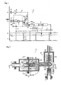
- ballast water detoxifying treatment system A of the present invention is applied to ballast water feed and drainage equipment of a ship.
- a ballast tank 1 is a tank for storing ballast water 2 and arranged from bow side to stem side of a ship. To keep balance of the ship, the inside of the ballast tank 1 is separated through the length and breadth by separate walls 111 and volume of the ballast water 2 storaged in the ballast tank 1 is controlled by ballast water distributer (not shown).
- An inlet opening 6 and a drainage opening 12 are arranged at alongside of the ship.
- An intake pipe 7 connects the inlet opening 6 to the ballast tank 1.
- a filtering device for intake F1 is provided in the inlet opening 6 of the intake pipe 7 or adjacent thereto.
- a high pressure pump 9, ballast water treatment equipment 3, a fungicide adding device 4 are arranged in a line and in this order.
- a water pumping up pipe 17 is connected to a diverging point P1 on the intake pipe 7 between the filtering device for intake F I and the high pressure pump 9. Accordingly, the ballast water 2 in the ballast tank 1 can be pumped up to the high pressure pump 9.
- a changeover valve R1 (comprises two valves R1a and R1b) is arranged on the diverging point P1.
- the ballast water treatment equipment 3 is provided downstream of the high pressure pump 9.
- the fungicide adding device 4 is provided downstream of the ballast water treatment equipment 3.
- the intake pipe 7 divaricated from the fungicide adding device 4 is connected to the ballast tank 1.
- a drainage pipe 11 divaricated from a diverging point P2 between the ballast water treatment equipment 3 and the fungicide adding device 4 is connected to the drainage opening 12.
- a changeover valve R2 (comprising two valves R2a and R2b) is arranged at the diverging point P2.
- a filtering device for drainage F2 is arranged at the drainage opening 12 or arranged near the opening 12.
- a fungicide removing device 16 is provided in the drainage pipe 11 at upstream of the filtering device for drainage F2.
- Activated carbon or the like is suitable as filled material for the fungicide removing device 16, because the activated carbon can adsorb the residual fungicide passed through the decomposition treatment with the ballast water treatment equipment 3 before draining to sea.
- the changeover valves R1, R2 are for changing over the directon of water flow.
- three-way electromagnetic valves are used for the changeover valves R1-R2, three-way electromagnetic valves.
- two pairs of valves Ra1-R1b, R2a-R2b performing same operation as the changeover valves R1, R2 are arranged near the diverging points P1, P2, respectively.
- the valve R1a is provided between the filtering device F1 near the inlet opening 6 and the diverging point P1.
- the valve R1b is provided in the water pumping up pipe 17.
- the valve R2a is provided between the fungicide adding device 4 and the diverging point P2.
- the valve R2b is provided in the drainage pipe 11.
- the filtering device for intake F1 comprises a coarse filtering part and a fine filtering part.
- Bulk material such as trash in the ballast water 2 taken from the inlet opening 6 alongside of the ship, and the aquatic creatures such as jelly fish, seaweed, or the like are removed in the coarse filtering part.
- a part of phytoplankton and animal plankton in the ballast water 2 is filtered in the fine filtering part.
- trash or the like in the ballast water 2 pumped from the ballast tank 1 is filtered in the filtering device for drainage F2.
- the ballast water treatment equipment 3 which is provided downstream of the high pressure pump 9 comprises a shear flow generator 31 at an entry-side and a swirl flow generator 37.
- the swirl flow generator 37 has a cylindrical main body 37a and a diffuser pipe 38 connected to an outlet of the cylindrical main body 37a.
- One embodiment is illustrated in Figs.2 to Fig.4 .
- the shear flow generator 31 comprises an anterior chamber 31 a, a posterior chamber 31 b having a plurality of parallel recessed venturi tubes 33 internally, and a connecting pipe 36 connecting the posterior chamber 31b to the swirl flow generator 37.
- the anterior chamber 31a is connected to the intake pipe 7 from the high pressure pump 9.
- anterior chamber 31 a is a cylinder with bottom face having expanded inner diameter for covering entry-openings 34 of the plurality of parallel recessed venturi tubes 33.
- the intake pipe 7 is connected to the bottom face of the anterior chamber 31a.
- An open side of the anterior chamber 31a is coupled with the posterior chamber 31b with a flange connection.
- the posterior chamber 31b is also a cylinder with a bottom face.
- the plurality of parrallel recessed venturi tubes 33 is inserted through a partition plate 31c oppilating an inlet opening of the posterior chamber 31b.
- One end of the connecting pipe 36 is connected to the bottom face (a downstream side face 31d), and the other end of the connecting pipe 36 is connected aslant to an outer surface on an outlet side of the cylindrical main body 37a.
- the other end of the connecting pipe 36 is connected tangentially to the outer surface on outlet side of the cylindrical main body 37a.
- Each of the recessed venturi tubes 33 comprises a throat 33b being a short and small cylinder, an inlet side cross-sectional area reducing part 33a having a polygonal shaped entry-opening 34, an outlet side cross-sectional area enlarging part 33c, and a shear flow generating recess 33d opening to the throat 33b.
- the cross-sectional shape of the inlet side cross-sectional area reducing part 33a is a streamline shape of which diameter is gradually reduced from the entry-opening 34 to the throat 33b and cross-sectional shape is transformed from the polygon to circular.
- the reason that the entry-opening 34 is polygonal shape is to arrange each of the entry-openings 34 adjacently not to create a flat part which is in a direction perpendicular to the flow and generates flow resistance.
- Triangle, square, pentagon, and hexagon can be selected as the polygonal shape.
- the pentagon shaped entry-openings 34 are arranged to make a honeycomb shape.
- the shape of the entry-opening 34 may be circular.
- the circular shaped entry-openings 34 make the flat part which generates flow resistance. Accordingly, the flat part generates pressure loss in the anterior chamber 31a.
- the diameter of the outlet side cross-sectional area enlarging part 33c is enlarged from the thoat 33b to outlet opening.
- the shear flow generating recess 33d is a disc-shaped space opening around the entire circumference of the throat 33b. By adjusting width and depth of the shear flow generating recess 33d, nano bubbles can be generated, when the ballast water 2 is passing through the throat 33b.
- the swirl flow generator 37 comprises the cylindrical main body 37a, a diffuser pipe 38 connected to outlet opening of the cylindrical main body 37a, and an outer air supplier 39 provided as necessary.
- the outer air supplier 39 comprises a pipe 39 connected to center of an upper face 37c of the cylindrical main body 37a, an outer air valve 39a provided in the pipe 39, and an outer air supplying pump 39b. If the inside of the swirl flow generator 37 is in negative pressure during operation, naturally-aspirated outer air can be supplied through the pipe 39c without using the outer air supplying pump 39b.
- the pipe 39c is arranged along a central axis of the cylindrical main body 37a. And the outer air is supplied through the pipe 39c into the cylindrical main body 37a. In this embodiment, one pipe 39c is connceted to an opening for air supply on the upper face 37c.
- a plurality of pipes 39c may be connected to a corresponding plurality of openings for air supply.
- the diffuser pipe 38 is provided from center of bottom face 37b on an outlet side of the cylindrical main body 37a. And inside of the diffuser pipe 38 is shaped as a smooth cone (not shown), one step (not shown), or multistep diffuser 38a-38c with circular cross-section shape (as shown in Fig.2 ) of which each diameter is gradually enlarged along the flow. And the diffuser pipe 38 is connceted to the intake pipe 7.
- ballast water treatment equipment 3 In this embodiment, one ballast water treatment equipment 3 is provided. However, a plural of the ballast water treatment equipment 3 may be provided in parallel depending on the amount of the ballast water to be treated. Furthermore, a plural of the ballast water treatment equipment 3 may also be provided in series for multiple treatment. An appropriate number of the recessed venturi tubes 33 is selected. If one recessed venturi tube 33 is used, the intake pipe 7 and the connecting pipe 36 are connected directly to the entry-opening 34 and the outlet opening 35 of the recessed venturi tube 33, respectively.
- ballast water 2 is pumped up from the ballast tank 1 and pressured into the throat 33b through the inlet side sectional area reducing part 33a rapidly by the high pressure pump 9. Strong shear flow is generated in the shear flow generating recess 33d by rapid expansion of the pressured ballast water 2. As a result, a large number of nano bubbles are generated with high concentration and quick release of energy due to fluid resonance phenomenon in the shear flow generating recess 33d. The nano bubbles have strong surface tension and exist with nearly zero volume in the ballast water 2.
- Some of the large number of nano bubbles are expanded (rebound) in size rapidly with decrease of pressure in the outlet side cross-sectional area enlarging part 33c. And blowout after rapid shrink in size of some of the nano bubbles in terms of the rapid rebound of the pressure generates microjets and impact waves.
- the residual nano bubbles flow into the swirl flow generator 37 through the posterior chamber 31b and the connecting pipe 36.
- the ballast water 2 including the fungicide and a large number of residual nano bubbles flow tangentially into the swirl flow generator 37 through the connecting pipe 36 at high velocity. And the ballast water 2 flows in a direction of the diffuser pipe 38 at the outlet of the swirl flow generator 37 while gyrating at high velocity. As a result, strong swirl flow is generated at this time. Consequently, with the centrifugal force of high velocity swirl, pressure at outer circumference of cylindrical main body 37a becomes higher than that at central part.
- opening the outer air valve 39a of the outer air supplier 39 and pressing the outer air from the outer air supplying pump 39b in operation (or natural suction of the outer air) into the swirl flow generator 37 makes gas-liquid mixing water mixed the air and the ballast water 2 including the fungicide with a large number of bubbles at outlet of the pipe 39c. And the mixed water flows with the swirl flow from the connecting pipe 36 to outlet substantially along center axis of the outer air supplier 39 while swirling.
- Difference in specific gravity between relatively-large size bubbles of the suction air and liquid of the ballast water 2 including the fungicide causes a certain level of gas-liquid separation by the centrifugal force affected to the liquid and the centripetal force affected to the bubbles. Then the large number of separated bubbles flows in the direction of outlet while changing diameter and taking on a cord in shape. In the meanwhile, a part of bubbles is sheared and teared apart by the swirl flow of high velocity swirling liquid. Consequently, fine bubbles, including nano bubbles, are generated in large numbers and are diffused rapidly in the cylindrical main body 37a.
- the diffuser pipe 38 is one or multistep diffuser 38a-38c
- decrease of water pressure by one or multiple rapid stepwise expansion when the ballast water 2 passes through the diffuser pipe 38 at inner circumference surface causes acceleration of generation of cavitation and generation of strong turbulence at corners of the steps. Then the ballast water 2 flows into the intake pipe 7 (in downstream side).
- the cascade field is defined as a rapid pressure fluctuation field where overwhelming cavitation with intervention of a large number of nano bubbles is occurred.
- the cascade field is rapidly changed from positive pressure field where is affected the centrifugal force of the swirl flow in circumference area of the cylindrical main body 37a to negative pressure field where is decreased the water pressure from the central part of the swirl flow to the diffuser pipe 3 8.
- the cascade field is a field towards a negative field where is decreased the water pressure from the outlet side cross-sectional area enlarging part 33c to the posterior chamber 31b and the connecting pipe 36 after generating a large number of nano bubbles in the shear flow generating recess 33d.
- the cavitation (otherwise known as ambient temperature boiling phenomenon) causes a significant erosion (cavitation erosion) which can erode metal faces and generates hundreds of meters per second in velocity of strong microjets and impact waves by asymmetricity shrinking with strong interference in the course of deterioration at pressure decreasing field.
- the impact waves eliminate the remaining aquatic creatures and fungi, and reinforces the chain of blowout of the other bubbles.
- the impact waves detoxify the (CIO - ) electrochemically and physicochemically (see Fig.6 ).
- the fungicide adding device 4 provided downstream of the ballast water treatment equipment 3 is to add sufficient quantity of fungicide for eliminating the aquatic creatures or the like barely managed to survive after passing through the cascade field of the ballast water treatment equipment 3 for up to 5 days (IMO standard).
- the fungicide adding device 4 adds appropriate quantities of sodium hypochlorite to the ballast water 2, or produces sodium hypochlorite by electrolysis of the ballast water 2.
- sodium hypochlorite is used as an example of the fungicide
- AC electrolysis apparatus is used as an example of the fungicide adding device 4.
- Three electrodes one of them is a ground electrode, the others are an anode electrode and a cathode electrode, respectively [Triode AC type].
- no ground electrode and a pair of anode and cathode electrodes [bipolar electrodes AC type].) are treated as one pair. And one or several pairs of the three electrodes are used for the AC electrolysis apparatus 4.
- the triode AC type is explained as an example.
- the AC electrolysis apparatus 4 is an inline type in this embodiment and has a double structure comprising an inner pipe 42 and a outer pipe 43. And electrodes 41 a-41 c are fixed between the inner pipe 42 and the outer pipe 43 to pass all amount of the ballast water 2 around the electrodes 41a-41c.
- the electrodes 41a-41c are perforated-plates (e.g. expanded metals, perforated metal) made of titanium or strainless steel and plated with platinum.
- the electrodes 41a-41c are arranged at regular intervals (equal intervals) at outlet end of the inner pipe 42. Furthermore, outer surfaces of these electrodes 41a-41c have contact with an inner surface of the outer pipe 43. Accordingly, the ballast water 2 passing between the outer pipe 43 and the inner pipe 42 totally passes through a reticulation constructed by the electrodes 41a-41c.
- the outer pipe 43 is connected to the intake pipe 7.
- the inner pipe 42 From entry opening to central part, the inner pipe 42 has many through holes 44 through which water passes. Support 45 is arranged three-way radially near the entry opening between the inner pipe 42 and the outer pipe 43 for suspending the inner pipe 42 at center of the outer pipe 43. Inside of the inner pipe 42, closing plates 46, 47 are provided in the end of the inner pipe 42, and between the end of the inner pipe 42 and the through hole 44 nearest the end, respectively. Electric wires connecting the electrodes 41 a-41 c to controller 15 are guided out through a support pipe 48 which is provided near the end of the outer pipe 43 between the inner pipe 42 and the outer pipe 43 and suspends the inner pipe 42 at center of the outer pipe 43.
- one AC electrolysis apparatus 4 is used. However, several AC electrolysis apparatuses 4 in parallel or in series may be used as appropriate.
- the inner pipe 42 is provided to support the electrodes 41a-41c in this embodiment. But the inner pipe 42 may not be necessary, when the electrodes 41a-41c can be fixed on inner surface of the outer pipe 43.
- the embodiment explained as above is operated as follows.
- the ballast water 2 is taken into the ballast tank 1 to counter too much uplift of unloaded ship.
- the valve R1b, R2b are closed, and the valve R1a, R2a are opened.
- the seawater is taken from the intake opening 6 by the high pressure pump 9.
- bulk material and bulk aquatic creatures are removed from the ballast water 2 by the filtering device for intake F1. And these filtered objects are returned to the sea of the unloading port by reverse washing.
- the ballast water 2 After passing through the filtering device for intake F1, the ballast water 2 is supplied totally to the nano bubbles generating equipment (ballast water treatment equipment) 3 by the high pressure pump 9 through the intake pipe 7.
- the outer air is supplied as necessary to the ballast water 2 by opening the outer air valve 39a and operating the outer air supplying pump 3 9b, or natural suction.
- countess numbers of fine nano bubbles and micro-nano bubbles are generated in the ballast water treatment equipment 3 by the workings as described above.
- the effect of the cavitation may only be used by closing the outer air valve 39a in intake and drainage of the ballast water 2. All or almost all the aquatic creatures or the like in the ballast water 2 are eliminated and injured during the ballast water 2 passage through the cascade field in the ballast water treatment equipment 3.
- minimum amount of sodium hypochlorite to be 3 mg/liter of chlorine
- the ballast water 2 is supplied to the ballast tank 1.
- the injured aquatic creatures or the like is eliminated by chlorine.
- the concentration of chlorine is decreased to approximately 1 mg/liter, because the chlorine is consumed.
- the residual chlorine inhibits re-activation and reproduce of residual aquatic creatures or the like.
- the ballast water 2 corresponding to weight of load is drained.
- the ballast water 2 in the ballast tank 1 is pumped up by the high pressure pump 9 after closing the valve R1a,R2a and opening the valve R1b, R2b.
- the residual chlorine in the pumped ballast water 2 is decomposed by passing through the ballast water treatment equipment 3 and is adsorbed by the activated carbon in the residual fungicide removing device 16. After filtered by the filtering device for drainage F2, the ballast water 2 is drained to the sea.
- Fig.6 shows test data indicating decomposition of residual chlorine with the nano bubble generating device of the present invention.
- the test simulates the decomposition of residual chlorine in drainage.
- the data shows that it was required more then 12 mg/liter of the chlorine concentration for eliminating the aquatic creatures or the like for up to 5 days by adding only sodium hypochlorite without using the nano bubble generating device. However, at least 3 mg/liter (at the time of adding) of the concentration was enough for eliminating for up to 5 days with using the nano bubble generating device.
- the concentration of the residual free chlorine in the ballast tank 1 after five days was I mg/liter.
- the residual free chlorine was measured by a residual chlorine measuring instrument (manufactured by Technoecho co, Ltd.).
- "Residual free chlorine” is defined as chlorine gas (Cl 2 ), hypochlorous acid (HOCl), and hypochlorite ion (OCl - ) existing in the test water (sea water in the ballast tank 1).
- the concentration of salt of sea water for the test was 3.64 mg/liter, temperature of the sea water was 4.3 °C, temperature of test atmosphere was 7°C, moisture content of the atmosphere was 42 %, and concentration of residual chlorine was 1.0 mg/liter.
- the sea water was pumped up by the high pressure pump and passed through the nano bubble generating device 3 in a flow rate of 138 liter/min.
- the nano bubble generating device 3 For the nano bubble generating device 3, one stage diffuser pipe and two stage diffuser pipe were provided. The test was conducted in case without supplying outer air from the outer air supplier 39 to the cylinder 37a (without outer air) and in case with suppling (with outer air). The number of the recessed venturi tubes 33 for the nano bubble generating device 3 was fifteen.
- the dechloridation was established in each case. Especially, in case that using one stage diffuser (with outer air) was the best, because the concentration of residual chlorine was 0.6 mg/liter (this meant that 0.4 mg/liter of sodium hypochlorite had been decomposed.). Therefore, using the nano bubble generating device 3 of the present invention makes drastic reduction of the activated carbon usage for adsorbing chlorine in drainage, and reduction of the sodium hypochlorite usage for damaging heavily the aquatic creatures or the like in water intake.
Landscapes
- Chemical & Material Sciences (AREA)
- Chemical Kinetics & Catalysis (AREA)
- Engineering & Computer Science (AREA)
- Environmental & Geological Engineering (AREA)
- Water Supply & Treatment (AREA)
- Organic Chemistry (AREA)
- Life Sciences & Earth Sciences (AREA)
- Hydrology & Water Resources (AREA)
- Combustion & Propulsion (AREA)
- Mechanical Engineering (AREA)
- Ocean & Marine Engineering (AREA)
- Health & Medical Sciences (AREA)
- General Health & Medical Sciences (AREA)
- Public Health (AREA)
- Toxicology (AREA)
- General Chemical & Material Sciences (AREA)
- Electrochemistry (AREA)
- Physical Water Treatments (AREA)
- Treatment Of Water By Oxidation Or Reduction (AREA)
- Water Treatment By Electricity Or Magnetism (AREA)
- Water Treatment By Sorption (AREA)
Claims (2)
- Système de traitement de détoxification d'eau de ballastage (A), comprenant :un réservoir de ballast (1) stockant de l'eau de ballastage (2) ;une conduite d'adduction (7) raccordant une ouverture d'adduction d'eau (6) et le réservoir de ballast (1) ;une pompe haute pression (9) fournie dans la conduite d'adduction (7) ;un équipement de traitement d'eau de ballastage (3) permettant d'alimenter de l'eau de ballastage (2) vers le réservoir de ballast (1) en passant par un dispositif d'ajout de fongicide (4), l'équipement de traitement d'eau de ballastage (3) comprenant :un générateur de flux de cisaillement (31) fourni dans la conduite d'adduction (7) entre l'ouverture d'adduction d'eau (6) et le réservoir de ballast (1), et recevant de l'eau de ballastage (2) en provenance de la pompe haute pression (9) ; etun générateur de flux turbulent (37) raccordé en aval du générateur de cisaillement (31) à une conduite de raccordement (36) ;dans lequel le générateur de flux de cisaillement (31) présente un ou plusieurs tube(s) de Venturi (33) agencés en parallèle, le ou chaque tube de Venturi présentant un renfoncement ;chaque tube de Venturi (33) avec renfoncement comprenant une partie de réduction de surface transversale côté entrée (33a) diminuant progressivement la surface transversale le long d'une direction d'écoulement ; une partie d'agrandissement de surface transversale côté sortie (33c) fournie en aval de la partie de réduction de surface transversale côté entrée (33a) et augmentant la surface transversale le long de la direction d'écoulement ; une gorge (33b) fournie entre la partie de réduction de surface transversale côté entrée (33a) et la partie d'agrandissement de surface transversale côté sortie (33c) ; et un renfoncement générant un flux de cisaillement (33d) débouchant sur la gorge (33b) ;dans lequel le générateur de flux turbulent (37) présente un cylindre (37a) raccordé de manière tangentielle à la conduite de raccordement (36) du générateur de flux de cisaillement (31) au niveau de sa surface latérale extérieure ; et une conduite de diffusion (38) présentant une surface transversale augmentant la surface circonférentielle intérieure le long de la direction d'écoulement et raccordée au dispositif d'ajout de fongicide (4) par l'intermédiaire de la conduite d'adduction (7) ;dans lequel l'équipement de traitement d'eau de ballastage (3) est fourni en aval de la pompe haute pression (9) ;le dispositif d'ajout de fongicide (4) fourni en aval de l'équipement de traitement d'eau de ballastage (3), et ajoutant du fongicide à l'eau de ballastage (2) alimentée à partir de l'équipement de traitement d'eau de ballastage (3) ;une conduite de pompage d'eau (17) raccordant le réservoir de ballast (1) à la conduite d'adduction (7) en amont de la pompe haute pression (9) ;une conduite de vidange (11) divergeant de la conduite d'adduction (7) en aval de l'équipement de traitement d'eau de ballastage (3) ;un dispositif d'élimination de fongicide résiduel (16) fourni dans la conduite de vidange (11) ;un robinet de jumelage (R1) fourni à proximité d'un point de divergence (P1) entre la conduite d'adduction (7) et la conduite de pompage d'eau (17), permettant de jumeler adduction et vidange ; etun robinet de jumelage (R2) fourni à proximité d'un point de divergence (P2) entre la conduite d'adduction (7) et la conduite de vidange (11) afin de jumeler adduction et vidange.
- Procédé permettant de traiter l'eau de ballastage en utilisant le système de traitement de détoxification d'eau de ballastage (A) selon la revendication 1, comprenant les étapes consistant à :lors d'une alimentation d'eau de ballastage (2) vers le réservoir de ballast (1),filtrer l'eau de ballastage (2) ;faire passer l'eau de ballastage (2) filtrée vers l'équipement de traitement d'eau de ballastage (3) ; etalimenter l'eau de ballastage (2) vers le réservoir de ballast (1) après ajout de fongicide,lors d'une vidange de l'eau de ballastage (2) à partir du réservoir de ballast (1),pomper l'eau de ballastage (2) à partir du réservoir de ballast (1) vers l'équipement de traitement d'eau de ballastage (3) ;éliminer le fongicide résiduel dans l'eau de ballastage (2) avec du charbon actif ; etvidanger.
Applications Claiming Priority (1)
| Application Number | Priority Date | Filing Date | Title |
|---|---|---|---|
| PCT/JP2010/001575 WO2011108032A1 (fr) | 2010-03-05 | 2010-03-05 | Dispositif de traitement d'une eau de ballastage, système pour rendre une eau de ballastage inoffensive utilisant le dispositif et procédé associé |
Publications (3)
| Publication Number | Publication Date |
|---|---|
| EP2476652A1 EP2476652A1 (fr) | 2012-07-18 |
| EP2476652A4 EP2476652A4 (fr) | 2014-02-26 |
| EP2476652B1 true EP2476652B1 (fr) | 2015-09-16 |
Family
ID=44541720
Family Applications (1)
| Application Number | Title | Priority Date | Filing Date |
|---|---|---|---|
| EP10825825.2A Active EP2476652B1 (fr) | 2010-03-05 | 2010-03-05 | Système de traitement d'une eau de ballastage et procédé |
Country Status (6)
| Country | Link |
|---|---|
| US (1) | US8557122B2 (fr) |
| EP (1) | EP2476652B1 (fr) |
| JP (1) | JP5551585B2 (fr) |
| KR (1) | KR101677479B1 (fr) |
| DK (1) | DK2476652T3 (fr) |
| WO (1) | WO2011108032A1 (fr) |
Families Citing this family (19)
| Publication number | Priority date | Publication date | Assignee | Title |
|---|---|---|---|---|
| US9688551B2 (en) | 2012-06-18 | 2017-06-27 | The United States Of America As Represented By The Secretary Of The Interior | Nozzle mixing apparatus and methods for treating water in ship ballast tanks |
| KR101306596B1 (ko) * | 2013-05-23 | 2013-09-10 | 삼건세기(주) | 밸러스트수 처리시스템 |
| JP5892208B2 (ja) * | 2014-07-30 | 2016-03-23 | 三菱電機株式会社 | 微細気泡発生装置 |
| JP2016104474A (ja) | 2014-08-22 | 2016-06-09 | 有限会社情報科学研究所 | 共鳴発泡と真空キャビテーションによるウルトラファインバブル製造方法及びウルトラファインバブル水製造装置。 |
| JP2016203082A (ja) * | 2015-04-21 | 2016-12-08 | 沖野 晃俊 | ラジカル機能液の製造方法およびラジカル機能液を用いた浄化方法 |
| JP6043900B1 (ja) * | 2016-02-12 | 2016-12-14 | 有限会社情報科学研究所 | 内燃機関エンジンによるウルトラファインバブルアクアジェット装置。 |
| JP6615662B2 (ja) * | 2016-03-18 | 2019-12-04 | 株式会社ノリタケカンパニーリミテド | 気泡含有液体の製造装置及びその使用方法 |
| JP6230738B1 (ja) * | 2016-09-01 | 2017-11-15 | 株式会社晃和工業 | 害敵水生々物殺滅用の多孔ノズル |
| KR20190126768A (ko) * | 2016-12-15 | 2019-11-12 | 마이클 스미스 | 유체 중에 캐비테이션을 생성하기 위한 시스템 및 방법 |
| KR102666811B1 (ko) | 2016-12-16 | 2024-05-20 | 엘지전자 주식회사 | 미세 기포 발생 시스템 |
| US10240243B2 (en) * | 2017-05-05 | 2019-03-26 | Hamilton Sundstrand Corporation | Flow distributor hole pattern |
| CN110678385A (zh) * | 2017-05-30 | 2020-01-10 | 日本邮船株式会社 | 压载水系统 |
| JP6960281B2 (ja) * | 2017-09-05 | 2021-11-05 | 株式会社富士計器 | 微細気泡液生成器 |
| WO2019069349A1 (fr) * | 2017-10-02 | 2019-04-11 | Hack Japan ホールディングス株式会社 | Dispositif générateur de bulles et méthode de génération de bulles |
| JPWO2019069350A1 (ja) * | 2017-10-02 | 2020-10-22 | Hack Japan ホールディングス株式会社 | 気泡生成装置、気泡生成方法 |
| WO2021096917A1 (fr) * | 2019-11-14 | 2021-05-20 | ACUDX Inc. | Dispositif d'émulsification et procédé d'émulsification |
| CN110773115B (zh) * | 2019-11-20 | 2022-07-12 | 苏州溪能环保科技有限公司 | 一种高效水处理装置 |
| KR102539609B1 (ko) * | 2022-08-04 | 2023-06-02 | 에스엔시스(주) | 버블 생성기를 구비하는 살균 여과 장치 및 이를 이용한 선박 평형수 처리 시스템 |
| CN117268846A (zh) * | 2023-10-09 | 2023-12-22 | 中船澄西船舶修造有限公司 | 一种防负压压载水取样系统的进气机构 |
Family Cites Families (36)
| Publication number | Priority date | Publication date | Assignee | Title |
|---|---|---|---|---|
| JPS6319569A (ja) | 1986-07-14 | 1988-01-27 | Toyo Commun Equip Co Ltd | 漏洩電流検出方法 |
| JP2623204B2 (ja) | 1993-02-26 | 1997-06-25 | 英雄 早川 | 水の改質方法 |
| AU2513995A (en) * | 1994-07-13 | 1996-02-16 | Angelo L. Mazzei | Gas injection into liquid and removal of undissolved gas |
| US5951923A (en) | 1996-05-23 | 1999-09-14 | Ebara Corporation | Vaporizer apparatus and film deposition apparatus therewith |
| JPH1074746A (ja) | 1996-05-23 | 1998-03-17 | Ebara Corp | 液体原料気化装置 |
| JPH108255A (ja) | 1996-06-20 | 1998-01-13 | Ebara Corp | 液体原料気化装置 |
| US5865995A (en) * | 1997-04-02 | 1999-02-02 | Nelson; William R. | System for treating liquids with a gas |
| US5863128A (en) * | 1997-12-04 | 1999-01-26 | Mazzei; Angelo L. | Mixer-injectors with twisting and straightening vanes |
| JP3650543B2 (ja) | 1999-07-01 | 2005-05-18 | 株式会社リンテック | 気化装置 |
| KR100412307B1 (ko) * | 2001-05-23 | 2003-12-31 | 주식회사두합크린텍 | 미세기포 발생장치 및 발생방법 |
| US20030015481A1 (en) * | 2001-06-28 | 2003-01-23 | Eidem Ola Magne | Method and apparatus for treating/disinfecting ballast water in ships |
| JP3763521B2 (ja) * | 2001-10-26 | 2006-04-05 | 株式会社オ−ラテック | マイクロバブル発生装置 |
| EP1499563B9 (fr) * | 2002-05-02 | 2014-03-05 | McNulty, Peter, Drummond | Systeme et procede de traitement d'eau de lestage |
| JP2005144320A (ja) * | 2003-11-14 | 2005-06-09 | Yamato:Kk | 流体混合装置 |
| US20080164217A1 (en) * | 2004-02-13 | 2008-07-10 | Kazuki Nishizawa | Method of Liquid Detoxification and Apparatus Therefor |
| WO2006003723A1 (fr) * | 2004-07-05 | 2006-01-12 | Daiki Ataka Engineering Co., Ltd. | Méthode de traitement de l'eau de ballast et appareil de traitement pour cela |
| JP2006088115A (ja) * | 2004-09-27 | 2006-04-06 | Kurita Water Ind Ltd | バラスト水の処理方法および装置 |
| US7624969B2 (en) * | 2004-09-30 | 2009-12-01 | Justin Schletz | Two-stage injector-mixer |
| JP2006212513A (ja) * | 2005-02-02 | 2006-08-17 | Ishikawajima Harima Heavy Ind Co Ltd | バラスト水浄化装置 |
| JP4085093B2 (ja) * | 2005-02-14 | 2008-04-30 | 三井造船株式会社 | バラスト水の処理装置 |
| US7776224B2 (en) * | 2005-06-10 | 2010-08-17 | Jfe Engineering Corporation | Apparatus for treating ballast water and method for treating ballast water |
| JP4844244B2 (ja) | 2005-06-10 | 2011-12-28 | Jfeエンジニアリング株式会社 | バラスト水処理装置及び処理方法 |
| JP5034210B2 (ja) * | 2005-10-14 | 2012-09-26 | Jfeエンジニアリング株式会社 | バラスト水処理装置 |
| JP4978002B2 (ja) * | 2005-12-07 | 2012-07-18 | Jfeエンジニアリング株式会社 | バラスト水処理方法 |
| JP2007069071A (ja) * | 2005-09-05 | 2007-03-22 | Sharp Corp | 微細気泡発生装置およびそれが組み込まれた微細気泡循環システム |
| US20100181260A1 (en) * | 2005-10-28 | 2010-07-22 | Resource Ballast Technologies (Proprietary) Limited | Method and Apparatus for Water Treatment to Eliminate Aquatic Organisms |
| JP3890076B1 (ja) * | 2006-02-03 | 2007-03-07 | 修 松本 | 気泡発生装置 |
| JP4272669B2 (ja) * | 2006-09-29 | 2009-06-03 | 社団法人日本海難防止協会 | 船舶バラスト水の処理装置 |
| JP4099200B2 (ja) * | 2006-10-17 | 2008-06-11 | 東フロコーポレーション株式会社 | 気液混合装置 |
| JP2008114099A (ja) * | 2006-10-31 | 2008-05-22 | Sanyo Facilities Industry Co Ltd | マイクロバブル生成装置及びバブル微小化器具。 |
| JP4370342B2 (ja) * | 2007-03-30 | 2009-11-25 | 大晃機械工業株式会社 | 水中微細物等の処理装置 |
| JP5132229B2 (ja) * | 2007-09-13 | 2013-01-30 | Jfeエンジニアリング株式会社 | ベンチュリ管装置及び該ベンチュリ管装置を用いたバラスト水処理装置 |
| JP2008100225A (ja) * | 2007-11-02 | 2008-05-01 | Toflo Corporation Kk | 気液混合装置 |
| JP2009136864A (ja) | 2007-11-16 | 2009-06-25 | Nippon Sozai Kk | マイクロバブル発生装置 |
| JP5269493B2 (ja) * | 2008-06-18 | 2013-08-21 | 佐藤工業株式会社 | マイクロバブル発生装置 |
| KR20100006610A (ko) * | 2008-07-10 | 2010-01-21 | 장학정 | 와류되는 유체를 이용한 온수 가열장치 |
-
2010
- 2010-03-05 EP EP10825825.2A patent/EP2476652B1/fr active Active
- 2010-03-05 DK DK10825825.2T patent/DK2476652T3/en active
- 2010-03-05 US US12/677,032 patent/US8557122B2/en active Active
- 2010-03-05 WO PCT/JP2010/001575 patent/WO2011108032A1/fr not_active Ceased
- 2010-03-05 KR KR1020127023001A patent/KR101677479B1/ko active Active
- 2010-03-05 JP JP2010510003A patent/JP5551585B2/ja active Active
Also Published As
| Publication number | Publication date |
|---|---|
| KR101677479B1 (ko) | 2016-11-18 |
| US8557122B2 (en) | 2013-10-15 |
| KR20130051433A (ko) | 2013-05-20 |
| US20120318751A1 (en) | 2012-12-20 |
| EP2476652A1 (fr) | 2012-07-18 |
| JPWO2011108032A1 (ja) | 2013-06-20 |
| DK2476652T3 (en) | 2015-12-14 |
| EP2476652A4 (fr) | 2014-02-26 |
| JP5551585B2 (ja) | 2014-07-16 |
| WO2011108032A1 (fr) | 2011-09-09 |
Similar Documents
| Publication | Publication Date | Title |
|---|---|---|
| DK2476652T3 (en) | System and method for treatment of ballast water | |
| US9255017B2 (en) | Liquid treatment methods and apparatus | |
| KR20100017410A (ko) | 물 처리 시스템 | |
| KR101118055B1 (ko) | 선박평형수의 인라인 처리 장치 | |
| JP4737157B2 (ja) | バラスト水処理装置およびバラスト水処理方法 | |
| US10287200B2 (en) | Method for treating ballast water and device for treating ballast water used therefor | |
| JP2006263563A (ja) | バラスト水中の微生物等の殺減装置 | |
| JP6593814B2 (ja) | 水素除去タンク及びそれを有するバラスト水処理システム | |
| KR102187152B1 (ko) | 밸러스트수 처리 장치 | |
| CN111517541A (zh) | 一种水处理装置 | |
| CN108975529A (zh) | 一种过滤、惰性气体船舶压载水联合处理装置及方法 | |
| CN216890228U (zh) | 一种压载水旋流分离器 | |
| KR102369944B1 (ko) | 미세기포 발생노즐 및 그를 포함하는 미세기포 발생장치 | |
| KR101865896B1 (ko) | 고효율 선박 평형수 처리 장치 | |
| KR20110114931A (ko) | 초음파 가진 장치를 이용한 전기분해방식 선박 평형수 처리장치의 성능 향상장치 | |
| KR100733541B1 (ko) | 전해식 밸러스터수 처리방법 및 처리장치 | |
| CN204714623U (zh) | 一种船舶压载水处理装置 | |
| KR20200142963A (ko) | 기체 용해 장치 및 그를 포함하는 미세기포 발생장치 | |
| AU2012203894B2 (en) | Ballast water treatment methods and apparatus | |
| KR20080058851A (ko) | 전해식 밸러스트 수처리장치의 수소가스 배출장치 | |
| CN106915844A (zh) | 一种海洋赤潮羟基自由基应急处置方法及船载装置 | |
| US9522829B2 (en) | Liquid treatment method and liquid treatment device used therein | |
| KR100815235B1 (ko) | 유량변화에 따라 dc전압 제어로 전해반응 속도를유도하는 폐수처리시스템 | |
| CN104925985A (zh) | 一种船舶压载水处理装置 |
Legal Events
| Date | Code | Title | Description |
|---|---|---|---|
| PUAI | Public reference made under article 153(3) epc to a published international application that has entered the european phase |
Free format text: ORIGINAL CODE: 0009012 |
|
| AK | Designated contracting states |
Kind code of ref document: A1 Designated state(s): AT BE BG CH CY CZ DE DK EE ES FI FR GB GR HR HU IE IS IT LI LT LU LV MC MK MT NL NO PL PT RO SE SI SK SM TR |
|
| 17P | Request for examination filed |
Effective date: 20120727 |
|
| DAX | Request for extension of the european patent (deleted) | ||
| A4 | Supplementary search report drawn up and despatched |
Effective date: 20140123 |
|
| RIC1 | Information provided on ipc code assigned before grant |
Ipc: C02F 1/467 20060101ALN20140117BHEP Ipc: B01F 5/04 20060101ALI20140117BHEP Ipc: C02F 1/50 20060101ALI20140117BHEP Ipc: C02F 1/00 20060101ALI20140117BHEP Ipc: C02F 1/76 20060101ALN20140117BHEP Ipc: B01F 5/00 20060101AFI20140117BHEP Ipc: B01F 3/04 20060101ALI20140117BHEP Ipc: C02F 103/00 20060101ALN20140117BHEP Ipc: B01F 13/00 20060101ALI20140117BHEP |
|
| RAP1 | Party data changed (applicant data changed or rights of an application transferred) |
Owner name: KOWA KOGYO CO., LTD. Owner name: YAMANISHI CORPORATION Owner name: TSUDA KAIUN CO., LTD. Owner name: TOHOKU UNIVERSITY Owner name: JAPAN BASIC MATERIAL CO., LTD. |
|
| 17Q | First examination report despatched |
Effective date: 20141219 |
|
| REG | Reference to a national code |
Ref country code: DE Ref legal event code: R079 Ref document number: 602010027629 Country of ref document: DE Free format text: PREVIOUS MAIN CLASS: C02F0001500000 Ipc: B01F0005000000 |
|
| GRAP | Despatch of communication of intention to grant a patent |
Free format text: ORIGINAL CODE: EPIDOSNIGR1 |
|
| RIC1 | Information provided on ipc code assigned before grant |
Ipc: B01F 5/04 20060101ALI20150326BHEP Ipc: C02F 1/467 20060101ALN20150326BHEP Ipc: B01F 13/00 20060101ALI20150326BHEP Ipc: C02F 103/00 20060101ALN20150326BHEP Ipc: B01F 3/04 20060101ALI20150326BHEP Ipc: C02F 1/50 20060101ALI20150326BHEP Ipc: C02F 1/76 20060101ALN20150326BHEP Ipc: C02F 1/00 20060101ALI20150326BHEP Ipc: B01F 5/00 20060101AFI20150326BHEP |
|
| INTG | Intention to grant announced |
Effective date: 20150414 |
|
| GRAS | Grant fee paid |
Free format text: ORIGINAL CODE: EPIDOSNIGR3 |
|
| GRAA | (expected) grant |
Free format text: ORIGINAL CODE: 0009210 |
|
| AK | Designated contracting states |
Kind code of ref document: B1 Designated state(s): AT BE BG CH CY CZ DE DK EE ES FI FR GB GR HR HU IE IS IT LI LT LU LV MC MK MT NL NO PL PT RO SE SI SK SM TR |
|
| REG | Reference to a national code |
Ref country code: GB Ref legal event code: FG4D |
|
| REG | Reference to a national code |
Ref country code: CH Ref legal event code: EP |
|
| REG | Reference to a national code |
Ref country code: IE Ref legal event code: FG4D |
|
| REG | Reference to a national code |
Ref country code: AT Ref legal event code: REF Ref document number: 749330 Country of ref document: AT Kind code of ref document: T Effective date: 20151015 |
|
| REG | Reference to a national code |
Ref country code: DE Ref legal event code: R096 Ref document number: 602010027629 Country of ref document: DE |
|
| REG | Reference to a national code |
Ref country code: DK Ref legal event code: T3 Effective date: 20151210 |
|
| REG | Reference to a national code |
Ref country code: SE Ref legal event code: TRGR |
|
| PG25 | Lapsed in a contracting state [announced via postgrant information from national office to epo] |
Ref country code: LV Free format text: LAPSE BECAUSE OF FAILURE TO SUBMIT A TRANSLATION OF THE DESCRIPTION OR TO PAY THE FEE WITHIN THE PRESCRIBED TIME-LIMIT Effective date: 20150916 Ref country code: LT Free format text: LAPSE BECAUSE OF FAILURE TO SUBMIT A TRANSLATION OF THE DESCRIPTION OR TO PAY THE FEE WITHIN THE PRESCRIBED TIME-LIMIT Effective date: 20150916 Ref country code: FI Free format text: LAPSE BECAUSE OF FAILURE TO SUBMIT A TRANSLATION OF THE DESCRIPTION OR TO PAY THE FEE WITHIN THE PRESCRIBED TIME-LIMIT Effective date: 20150916 Ref country code: GR Free format text: LAPSE BECAUSE OF FAILURE TO SUBMIT A TRANSLATION OF THE DESCRIPTION OR TO PAY THE FEE WITHIN THE PRESCRIBED TIME-LIMIT Effective date: 20151217 |
|
| REG | Reference to a national code |
Ref country code: NO Ref legal event code: T2 Effective date: 20150916 |
|
| REG | Reference to a national code |
Ref country code: LT Ref legal event code: MG4D Ref country code: NL Ref legal event code: FP |
|
| REG | Reference to a national code |
Ref country code: AT Ref legal event code: MK05 Ref document number: 749330 Country of ref document: AT Kind code of ref document: T Effective date: 20150916 |
|
| PG25 | Lapsed in a contracting state [announced via postgrant information from national office to epo] |
Ref country code: HR Free format text: LAPSE BECAUSE OF FAILURE TO SUBMIT A TRANSLATION OF THE DESCRIPTION OR TO PAY THE FEE WITHIN THE PRESCRIBED TIME-LIMIT Effective date: 20150916 |
|
| PG25 | Lapsed in a contracting state [announced via postgrant information from national office to epo] |
Ref country code: CZ Free format text: LAPSE BECAUSE OF FAILURE TO SUBMIT A TRANSLATION OF THE DESCRIPTION OR TO PAY THE FEE WITHIN THE PRESCRIBED TIME-LIMIT Effective date: 20150916 Ref country code: ES Free format text: LAPSE BECAUSE OF FAILURE TO SUBMIT A TRANSLATION OF THE DESCRIPTION OR TO PAY THE FEE WITHIN THE PRESCRIBED TIME-LIMIT Effective date: 20150916 Ref country code: SK Free format text: LAPSE BECAUSE OF FAILURE TO SUBMIT A TRANSLATION OF THE DESCRIPTION OR TO PAY THE FEE WITHIN THE PRESCRIBED TIME-LIMIT Effective date: 20150916 Ref country code: IT Free format text: LAPSE BECAUSE OF FAILURE TO SUBMIT A TRANSLATION OF THE DESCRIPTION OR TO PAY THE FEE WITHIN THE PRESCRIBED TIME-LIMIT Effective date: 20150916 Ref country code: IS Free format text: LAPSE BECAUSE OF FAILURE TO SUBMIT A TRANSLATION OF THE DESCRIPTION OR TO PAY THE FEE WITHIN THE PRESCRIBED TIME-LIMIT Effective date: 20160116 Ref country code: EE Free format text: LAPSE BECAUSE OF FAILURE TO SUBMIT A TRANSLATION OF THE DESCRIPTION OR TO PAY THE FEE WITHIN THE PRESCRIBED TIME-LIMIT Effective date: 20150916 |
|
| PG25 | Lapsed in a contracting state [announced via postgrant information from national office to epo] |
Ref country code: AT Free format text: LAPSE BECAUSE OF FAILURE TO SUBMIT A TRANSLATION OF THE DESCRIPTION OR TO PAY THE FEE WITHIN THE PRESCRIBED TIME-LIMIT Effective date: 20150916 Ref country code: RO Free format text: LAPSE BECAUSE OF FAILURE TO SUBMIT A TRANSLATION OF THE DESCRIPTION OR TO PAY THE FEE WITHIN THE PRESCRIBED TIME-LIMIT Effective date: 20150916 Ref country code: PL Free format text: LAPSE BECAUSE OF FAILURE TO SUBMIT A TRANSLATION OF THE DESCRIPTION OR TO PAY THE FEE WITHIN THE PRESCRIBED TIME-LIMIT Effective date: 20150916 |
|
| REG | Reference to a national code |
Ref country code: DE Ref legal event code: R097 Ref document number: 602010027629 Country of ref document: DE |
|
| PLBE | No opposition filed within time limit |
Free format text: ORIGINAL CODE: 0009261 |
|
| STAA | Information on the status of an ep patent application or granted ep patent |
Free format text: STATUS: NO OPPOSITION FILED WITHIN TIME LIMIT |
|
| 26N | No opposition filed |
Effective date: 20160617 |
|
| PG25 | Lapsed in a contracting state [announced via postgrant information from national office to epo] |
Ref country code: BE Free format text: LAPSE BECAUSE OF NON-PAYMENT OF DUE FEES Effective date: 20160331 |
|
| PG25 | Lapsed in a contracting state [announced via postgrant information from national office to epo] |
Ref country code: MC Free format text: LAPSE BECAUSE OF FAILURE TO SUBMIT A TRANSLATION OF THE DESCRIPTION OR TO PAY THE FEE WITHIN THE PRESCRIBED TIME-LIMIT Effective date: 20150916 Ref country code: LU Free format text: LAPSE BECAUSE OF FAILURE TO SUBMIT A TRANSLATION OF THE DESCRIPTION OR TO PAY THE FEE WITHIN THE PRESCRIBED TIME-LIMIT Effective date: 20160305 |
|
| REG | Reference to a national code |
Ref country code: CH Ref legal event code: PL |
|
| PG25 | Lapsed in a contracting state [announced via postgrant information from national office to epo] |
Ref country code: SI Free format text: LAPSE BECAUSE OF FAILURE TO SUBMIT A TRANSLATION OF THE DESCRIPTION OR TO PAY THE FEE WITHIN THE PRESCRIBED TIME-LIMIT Effective date: 20150916 |
|
| REG | Reference to a national code |
Ref country code: IE Ref legal event code: MM4A |
|
| PG25 | Lapsed in a contracting state [announced via postgrant information from national office to epo] |
Ref country code: BE Free format text: LAPSE BECAUSE OF FAILURE TO SUBMIT A TRANSLATION OF THE DESCRIPTION OR TO PAY THE FEE WITHIN THE PRESCRIBED TIME-LIMIT Effective date: 20150916 |
|
| REG | Reference to a national code |
Ref country code: FR Ref legal event code: ST Effective date: 20161130 |
|
| PG25 | Lapsed in a contracting state [announced via postgrant information from national office to epo] |
Ref country code: IE Free format text: LAPSE BECAUSE OF NON-PAYMENT OF DUE FEES Effective date: 20160305 Ref country code: LI Free format text: LAPSE BECAUSE OF NON-PAYMENT OF DUE FEES Effective date: 20160331 Ref country code: CH Free format text: LAPSE BECAUSE OF NON-PAYMENT OF DUE FEES Effective date: 20160331 Ref country code: FR Free format text: LAPSE BECAUSE OF NON-PAYMENT OF DUE FEES Effective date: 20160331 |
|
| PG25 | Lapsed in a contracting state [announced via postgrant information from national office to epo] |
Ref country code: MT Free format text: LAPSE BECAUSE OF FAILURE TO SUBMIT A TRANSLATION OF THE DESCRIPTION OR TO PAY THE FEE WITHIN THE PRESCRIBED TIME-LIMIT Effective date: 20150916 |
|
| PG25 | Lapsed in a contracting state [announced via postgrant information from national office to epo] |
Ref country code: HU Free format text: LAPSE BECAUSE OF FAILURE TO SUBMIT A TRANSLATION OF THE DESCRIPTION OR TO PAY THE FEE WITHIN THE PRESCRIBED TIME-LIMIT; INVALID AB INITIO Effective date: 20100305 Ref country code: SM Free format text: LAPSE BECAUSE OF FAILURE TO SUBMIT A TRANSLATION OF THE DESCRIPTION OR TO PAY THE FEE WITHIN THE PRESCRIBED TIME-LIMIT Effective date: 20150916 Ref country code: CY Free format text: LAPSE BECAUSE OF FAILURE TO SUBMIT A TRANSLATION OF THE DESCRIPTION OR TO PAY THE FEE WITHIN THE PRESCRIBED TIME-LIMIT Effective date: 20150916 |
|
| PG25 | Lapsed in a contracting state [announced via postgrant information from national office to epo] |
Ref country code: PT Free format text: LAPSE BECAUSE OF FAILURE TO SUBMIT A TRANSLATION OF THE DESCRIPTION OR TO PAY THE FEE WITHIN THE PRESCRIBED TIME-LIMIT Effective date: 20150916 Ref country code: MT Free format text: LAPSE BECAUSE OF FAILURE TO SUBMIT A TRANSLATION OF THE DESCRIPTION OR TO PAY THE FEE WITHIN THE PRESCRIBED TIME-LIMIT Effective date: 20160331 Ref country code: MK Free format text: LAPSE BECAUSE OF FAILURE TO SUBMIT A TRANSLATION OF THE DESCRIPTION OR TO PAY THE FEE WITHIN THE PRESCRIBED TIME-LIMIT Effective date: 20150916 Ref country code: TR Free format text: LAPSE BECAUSE OF FAILURE TO SUBMIT A TRANSLATION OF THE DESCRIPTION OR TO PAY THE FEE WITHIN THE PRESCRIBED TIME-LIMIT Effective date: 20150916 |
|
| PG25 | Lapsed in a contracting state [announced via postgrant information from national office to epo] |
Ref country code: BG Free format text: LAPSE BECAUSE OF FAILURE TO SUBMIT A TRANSLATION OF THE DESCRIPTION OR TO PAY THE FEE WITHIN THE PRESCRIBED TIME-LIMIT Effective date: 20150916 |
|
| REG | Reference to a national code |
Ref country code: DE Ref legal event code: R079 Ref document number: 602010027629 Country of ref document: DE Free format text: PREVIOUS MAIN CLASS: B01F0005000000 Ipc: B01F0025000000 |
|
| PGFP | Annual fee paid to national office [announced via postgrant information from national office to epo] |
Ref country code: NL Payment date: 20240108 Year of fee payment: 15 |
|
| PGFP | Annual fee paid to national office [announced via postgrant information from national office to epo] |
Ref country code: DE Payment date: 20231229 Year of fee payment: 15 Ref country code: GB Payment date: 20240108 Year of fee payment: 15 |
|
| REG | Reference to a national code |
Ref country code: DE Ref legal event code: R119 Ref document number: 602010027629 Country of ref document: DE |
|
| REG | Reference to a national code |
Ref country code: NL Ref legal event code: MM Effective date: 20250401 |
|
| GBPC | Gb: european patent ceased through non-payment of renewal fee |
Effective date: 20250305 |
|
| PG25 | Lapsed in a contracting state [announced via postgrant information from national office to epo] |
Ref country code: NL Free format text: LAPSE BECAUSE OF NON-PAYMENT OF DUE FEES Effective date: 20250401 |
|
| PG25 | Lapsed in a contracting state [announced via postgrant information from national office to epo] |
Ref country code: DE Free format text: LAPSE BECAUSE OF NON-PAYMENT OF DUE FEES Effective date: 20251001 |
|
| PG25 | Lapsed in a contracting state [announced via postgrant information from national office to epo] |
Ref country code: GB Free format text: LAPSE BECAUSE OF NON-PAYMENT OF DUE FEES Effective date: 20250305 |
|
| PGFP | Annual fee paid to national office [announced via postgrant information from national office to epo] |
Ref country code: SE Payment date: 20260128 Year of fee payment: 17 |
|
| PGFP | Annual fee paid to national office [announced via postgrant information from national office to epo] |
Ref country code: NO Payment date: 20260310 Year of fee payment: 17 Ref country code: DK Payment date: 20260313 Year of fee payment: 17 |