EP2476778A1 - Suscepteur. - Google Patents
Suscepteur. Download PDFInfo
- Publication number
- EP2476778A1 EP2476778A1 EP11189645A EP11189645A EP2476778A1 EP 2476778 A1 EP2476778 A1 EP 2476778A1 EP 11189645 A EP11189645 A EP 11189645A EP 11189645 A EP11189645 A EP 11189645A EP 2476778 A1 EP2476778 A1 EP 2476778A1
- Authority
- EP
- European Patent Office
- Prior art keywords
- susceptor
- slices
- disk
- flow path
- Prior art date
- Legal status (The legal status is an assumption and is not a legal conclusion. Google has not performed a legal analysis and makes no representation as to the accuracy of the status listed.)
- Withdrawn
Links
Images



Classifications
-
- C—CHEMISTRY; METALLURGY
- C23—COATING METALLIC MATERIAL; COATING MATERIAL WITH METALLIC MATERIAL; CHEMICAL SURFACE TREATMENT; DIFFUSION TREATMENT OF METALLIC MATERIAL; COATING BY VACUUM EVAPORATION, BY SPUTTERING, BY ION IMPLANTATION OR BY CHEMICAL VAPOUR DEPOSITION, IN GENERAL; INHIBITING CORROSION OF METALLIC MATERIAL OR INCRUSTATION IN GENERAL
- C23C—COATING METALLIC MATERIAL; COATING MATERIAL WITH METALLIC MATERIAL; SURFACE TREATMENT OF METALLIC MATERIAL BY DIFFUSION INTO THE SURFACE, BY CHEMICAL CONVERSION OR SUBSTITUTION; COATING BY VACUUM EVAPORATION, BY SPUTTERING, BY ION IMPLANTATION OR BY CHEMICAL VAPOUR DEPOSITION, IN GENERAL
- C23C16/00—Chemical coating by decomposition of gaseous compounds, without leaving reaction products of surface material in the coating, i.e. chemical vapour deposition [CVD] processes
- C23C16/44—Chemical coating by decomposition of gaseous compounds, without leaving reaction products of surface material in the coating, i.e. chemical vapour deposition [CVD] processes characterised by the method of coating
- C23C16/458—Chemical coating by decomposition of gaseous compounds, without leaving reaction products of surface material in the coating, i.e. chemical vapour deposition [CVD] processes characterised by the method of coating characterised by the method used for supporting substrates in the reaction chamber
- C23C16/4582—Rigid and flat substrates, e.g. plates or discs
- C23C16/4583—Rigid and flat substrates, e.g. plates or discs the substrate being supported substantially horizontally
- C23C16/4584—Rigid and flat substrates, e.g. plates or discs the substrate being supported substantially horizontally the substrate being rotated
-
- C—CHEMISTRY; METALLURGY
- C23—COATING METALLIC MATERIAL; COATING MATERIAL WITH METALLIC MATERIAL; CHEMICAL SURFACE TREATMENT; DIFFUSION TREATMENT OF METALLIC MATERIAL; COATING BY VACUUM EVAPORATION, BY SPUTTERING, BY ION IMPLANTATION OR BY CHEMICAL VAPOUR DEPOSITION, IN GENERAL; INHIBITING CORROSION OF METALLIC MATERIAL OR INCRUSTATION IN GENERAL
- C23C—COATING METALLIC MATERIAL; COATING MATERIAL WITH METALLIC MATERIAL; SURFACE TREATMENT OF METALLIC MATERIAL BY DIFFUSION INTO THE SURFACE, BY CHEMICAL CONVERSION OR SUBSTITUTION; COATING BY VACUUM EVAPORATION, BY SPUTTERING, BY ION IMPLANTATION OR BY CHEMICAL VAPOUR DEPOSITION, IN GENERAL
- C23C16/00—Chemical coating by decomposition of gaseous compounds, without leaving reaction products of surface material in the coating, i.e. chemical vapour deposition [CVD] processes
- C23C16/44—Chemical coating by decomposition of gaseous compounds, without leaving reaction products of surface material in the coating, i.e. chemical vapour deposition [CVD] processes characterised by the method of coating
- C23C16/458—Chemical coating by decomposition of gaseous compounds, without leaving reaction products of surface material in the coating, i.e. chemical vapour deposition [CVD] processes characterised by the method of coating characterised by the method used for supporting substrates in the reaction chamber
- C23C16/4582—Rigid and flat substrates, e.g. plates or discs
- C23C16/4583—Rigid and flat substrates, e.g. plates or discs the substrate being supported substantially horizontally
- C23C16/4586—Elements in the interior of the support, e.g. electrodes, heating or cooling devices
-
- C—CHEMISTRY; METALLURGY
- C30—CRYSTAL GROWTH
- C30B—SINGLE-CRYSTAL GROWTH; UNIDIRECTIONAL SOLIDIFICATION OF EUTECTIC MATERIAL OR UNIDIRECTIONAL DEMIXING OF EUTECTOID MATERIAL; REFINING BY ZONE-MELTING OF MATERIAL; PRODUCTION OF A HOMOGENEOUS POLYCRYSTALLINE MATERIAL WITH DEFINED STRUCTURE; SINGLE CRYSTALS OR HOMOGENEOUS POLYCRYSTALLINE MATERIAL WITH DEFINED STRUCTURE; AFTER-TREATMENT OF SINGLE CRYSTALS OR A HOMOGENEOUS POLYCRYSTALLINE MATERIAL WITH DEFINED STRUCTURE; APPARATUS THEREFOR
- C30B25/00—Single-crystal growth by chemical reaction of reactive gases, e.g. chemical vapour-deposition growth
- C30B25/02—Epitaxial-layer growth
- C30B25/12—Substrate holders or susceptors
-
- C—CHEMISTRY; METALLURGY
- C30—CRYSTAL GROWTH
- C30B—SINGLE-CRYSTAL GROWTH; UNIDIRECTIONAL SOLIDIFICATION OF EUTECTIC MATERIAL OR UNIDIRECTIONAL DEMIXING OF EUTECTOID MATERIAL; REFINING BY ZONE-MELTING OF MATERIAL; PRODUCTION OF A HOMOGENEOUS POLYCRYSTALLINE MATERIAL WITH DEFINED STRUCTURE; SINGLE CRYSTALS OR HOMOGENEOUS POLYCRYSTALLINE MATERIAL WITH DEFINED STRUCTURE; AFTER-TREATMENT OF SINGLE CRYSTALS OR A HOMOGENEOUS POLYCRYSTALLINE MATERIAL WITH DEFINED STRUCTURE; APPARATUS THEREFOR
- C30B25/00—Single-crystal growth by chemical reaction of reactive gases, e.g. chemical vapour-deposition growth
- C30B25/02—Epitaxial-layer growth
- C30B25/14—Feed and outlet means for the gases; Modifying the flow of the reactive gases
Definitions
- the present disclosure relates to susceptors and chemical vapor deposition (CVD) apparatuses including the same.
- CVD apparatuses use a chemical reaction to form a thin film on a member on which a material is to be deposited (the member generally including a substrate such as a semiconductor wafer).
- the member generally including a substrate such as a semiconductor wafer.
- CVD apparatus by transmitting a reaction gas having a high vapor pressure to a substrate heated in a vacuum chamber, a membrane formed of the reaction gas is grown on the substrate.
- MOCVD metal organic chemical vapor deposition
- a technology of uniform growing a thin film on a plurality of members on which a material is to be deposited is important since the technology allows deposition to occur on all the plurality of members at once.
- the members are placed on satellite disks, and the satellite disks are each contained in one of a plurality of pockets prepared on susceptors. In order to uniformly grow a thin film on a member on which a material is to be deposited, not only the susceptor but also the satellite disk may rotate.
- susceptors having improved structures and chemical vapor deposition (CVD) apparatuses including the same.
- a susceptor for a disk-form chemical vapor deposition (CVD) apparatus includes a plurality of susceptor slices that form a disk when combined together; and at least one pocket disposed on an upper surface of each of the plurality of susceptor slices and containing a member on which a material is to be deposited, wherein, a connection part is formed between side surfaces of neighboring susceptor slices and allows the plurality of susceptor slices to be combined to each other in a separable/detachable manner.
- CVD chemical vapor deposition
- the plurality of susceptor slices each may be fan shaped.
- connection part may include a concave portion formed on one side of each of the plurality of susceptor slices and a convex portion formed on another side of each of the plurality of susceptor slices, the concave portion and the convex portion being engaged with each other.
- connection part may include a groove part formed on one side of each of the plurality of susceptor slices and extending long in a diameter direction, and a protrusion part formed on another side of each of the plurality of susceptor slices.
- Each of the plurality of susceptor slices may include a susceptor flow path that supplies a flow gas to the at least one pocket.
- a chemical vapor deposition (CVD) apparatus includes a susceptor comprising a plurality of susceptor slices that form a disk when combined together and at least one pocket disposed on an upper surface of each of the plurality of susceptor slices and containing a member on which a material is to be deposited; supporters for supporting the susceptor while injecting a flow gas to the susceptor to rotate the member; a reaction gas injector for injecting a reaction gas including a deposition material to be deposited on the member; and a chamber comprising the susceptor, the supporters, and the reaction gas injector, wherein the susceptor is for a disk-form CVD apparatus and includes: a plurality of susceptor slices that form a disk when combined together; and at least one pocket disposed on an upper surface of each of the plurality of susceptor slices and containing a member on which a material is to be deposited, and wherein a connection part is formed between side surfaces of neighboring susceptor slices and allows the
- FIG. 1 is a cross-sectional view schematically illustrating a chemical vapor deposition (CVD) apparatus according to an embodiment of the present invention
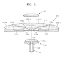
- FIG. 2 is a cross-sectional perspective view schematically illustrating a susceptor of the CVD apparatus of FIG. 1 ;
- FIG. 3 is a plan view of the susceptor of FIG. 2 ;
- FIG. 4 is a perspective view illustrating one slice of the susceptor of FIG. 2 .
- FIG. 1 is a cross-sectional view schematically illustrating a chemical vapor deposition (CVD) apparatus 100 according to an embodiment of the present invention
- FIG. 2 is a cross-sectional perspective view schematically illustrating a susceptor 110 of the CVD apparatus 100
- FIG. 3 is a plan view of the susceptor 110
- FIG. 4 is a perspective view illustrating one slice 110-1 of the susceptor 110.
- CVD chemical vapor deposition
- the CVD apparatus 100 includes the susceptor 110, supporters 130, 140, and 150 for supporting the susceptor 110 while injecting a flow gas G1, a heater 175 for heating the susceptor 110, a reaction gas injector 180 for supplying a reaction gas G2, a chamber 190 for accommodating the susceptor 110 and a nozzle 185 of the reaction gas injector 180, and a gas discharger 195 for discharging the flow gas G1 and the reaction gas G2 in the chamber 190.
- the susceptor 110 is in a disk form having a hole 110a.
- the susceptor 110 includes a plurality of susceptor slices 110-1, 110-2, 110-3, 110-4, 110-5, 110-6, 110-7, and 110-8 that form a disk when combined together.
- the susceptor 110 includes eight susceptor slices 110-1, 110-2, 110-3, 110-4, 110-5, 110-6, 110-7, and 110-8.
- the present invention is not limited thereto and the number of susceptor slices may vary according to sizes of the susceptor 110 and pockets 111.
- FIG. 4 illustrates the susceptor slice 110-1.
- the susceptor slice 110-1 may be fan shaped having an inner surface 110-1 a that forms a portion of the hole 110a of the susceptor 110, an outer surface 110-1b that forms an arc, and side surfaces 110-1c and 110-1d contacting neighboring susceptor slices.
- the side surface 110-1c includes a protrusion part 112 and the side surface 110-1d includes a groove part 113.
- the protrusion part 112 may be formed extending long in a diameter direction, or a plurality of protrusion parts 112 may be discontinuously formed in a diameter direction.
- the groove part 113 may be formed extending long in a diameter direction.
- the protrusion part 112 of one slice and the groove part 113 of another slice are complementarily with each other and together form a connection part that allows the plurality of susceptor slices 110-1, 110-2, 110-3, 110-4, 110-5, 110-6, 110-7, and 110-8 to be combined in a separable/detchable manner. That is, the protrusion part 112 of the susceptor slice 110-1 may be fixed into the neighboring groove part 113 prepared in the susceptor slice 110-8 of FIG. 3 , and the protrusion part 112 of the susceptor slice 110-2 of FIG. 3 may be fixed into the neighboring groove part 113 of the susceptor slice 110-1 in order to combine the susceptor slice 110-1 and both susceptor slices 110-2 and 110-8 to each other.
- connection part may be easily disassembled using a sliding method.
- any one of the plurality of susceptor slices 110-1, 110-2, 110-3, 110-4, 110-5, 110-6, 110-7, and 110-8 is broken, the broken susceptor slice may be easily removed and replaced by an extra susceptor slice and thus maintenance is possible.
- the plurality of susceptor slices 110-1, 110-2, 110-3, 110-4, 110-5, 110-6, 110-7, and 110-8 have the same shape and thus there is only one kind of slice. In some cases, there may be a plurality of shapes among the plurality of susceptor slices 110-1, 110-2, 110-3, 110-4, 110-5, 110-6, 110-7, and 110-8.
- both side surfaces 110-1c and 110-1d of some slices may include only the protrusion part 112 and both side surfaces 110-1 c and 110-1 d of other slices may include only the groove part 113 and thus these two kinds of slices may be alternately combined to each other.
- the protrusion part 112 and the groove part 113 are examples of the connection part; however, the present invention is not limited thereto.
- a detachable screw may be used as a connection member.
- At least one pocket 111 is prepared on an upper surface of each of the plurality of susceptor slices 110-1, 110-2, 110-3, 110-4, 110-5, 110-6, 110-7, and 110-8.
- one pocket 111 is included in each of the susceptor slices 110-1, 110-2, 110-3, 110-4, 110-5, 110-6, 110-7, and 110-8; however, the present invention is not limited thereto.
- a plurality of pockets 111 may be included in each of the susceptor slices 110-1, 110-2, 110-3, 110-4, 110-5, 110-6, 110-7, and 110-8.
- the pocket 111 is a groove part that is concave to a predetermined depth from the upper surface of each of the plurality of susceptor slices 110-1, 110-2, 110-3, 110-4, 110-5, 110-6, 110-7, and 110-8.
- a disk type satellite disk 120 of FIG. 1 is accommodated in the pocket 111.
- a center pin 111a may be disposed at the center of the pocket 111 so that the satellite disk 120 is not separated from the pocket 111 while the satellite disk 120 is rotating.
- a susceptor flow path 115 for supplying the flow gas G1 to the pocket 111 is formed in each of the plurality of susceptor slices 110-1, 110-2, 110-3, 110-4, 110-5, 110-6, 110-7, and 110-8.
- An inlet 115a of the susceptor flow path 115 may be disposed in the side of the hole 110a of the susceptor 110.
- An outlet 115b of the susceptor flow path 115 is disposed at a bottom of the pocket 111.
- a plurality of outlets 115b of the susceptor flow path 115 may be disposed at the bottom of the pocket 111. In this case, one susceptor flow path 115 may diverge into the plurality of outlets 115b.
- the susceptor flow path 115 extends long in a straight line from the inlet 115a to a lower part of the pocket 111 and is bent to the outlet 115b on the pocket 111 from the lower part of the pocket 111.
- the inlet 115a of the susceptor flow path 115 may be disposed on a lower surface of the susceptor 110.
- a groove in a spiral form that connects to the outlet 115b for supplying the flow gas G2 may be disposed at the bottom of the pocket 111.
- the flow gas G1 discharged from the outlet 115b suspends the satellite disk 120 placed on the pocket 111 and thus a frictional force between the satellite disk 120 and the bottom of the pocket 111 may be significantly decreases due to a cushioning function of the flow gas G1 when rotating the satellite disk 120.
- the flow gas G1 discharged from the outlet 115b is bent in a spiral form along the spiral groove connected to the outlet 115b and flows from an inner of the pocket 111 out of the pocket 111 so that the satellite disk 120 may be rotated by the flow gas G1.
- a flow gas exhaust pipe that may exhaust the flow gas G1 out of the susceptor 110 may be disposed in an edge of the pocket 111.
- a material used to form the susceptor 110 may vary according to a method of heating a member disposed on the satellite disk 120 and on which a material is to be deposited.
- the susceptor 110 may be formed of a material that may be heated by induction heating.
- the susceptor 110 may be formed of graphite.
- hardness strengthening coating may be performed on the susceptor 110.
- the susceptor 110 may be formed by coating silicon carbide SiC on graphite.
- the susceptor 110 As the susceptor 110 itself is heated, a member disposed thereon and on which a material is to be deposited is heated. Thus, degradation due to heat is generated, and accordingly, silicon carbide SiC coated on the susceptor 110 may be removed or the susceptor 110 may be broken. For example, due to a difference between a temperature of the susceptor 110 and a temperature of the flow gas G1 as the flow gas G1 passes through the susceptor flow path 115, elements surrounding the susceptor flow path 115 as the flow gas G1 passes through the path 115 are vulnerable to heat shock and thus may break. Also, the susceptor 110 may be broken by carelessness of a worker.
- the supporters 130, 140, and 150 which supports the susceptor 110, may include a supporting disk 130 disposed below the susceptor 110, an upper joining plate 140 disposed on top of the susceptor 110, and a supporting tube 150 as a shaft combined to the supporting disk 130.
- the upper joining plate 140 and the supporting disk 130 may be connected to each other by using a well-known connection member, and the susceptor 110 interposed between the upper joining plate 140 and the supporting disk 130 is fixed with respect to the supporting disk 130.
- the supporting disk 130 is combined to the supporting tube 150 and the supporting tube 150 is connected to a flow gas injector 160.
- the supporting disk 130 includes a supporting disk flow path 135 through which the flow gas G1 flows.
- the supporting disk flow path 135 is connected to a supporting tube flow path 155 of the supporting tube 150, and an outlet 135a of the supporting disk flow path 135 is disposed on a peripheral surface of the supporting disk 130.
- the outlet 135a of the supporting disk flow path 135 faces the inlet 115a of the susceptor flow path 115.
- the outlet 135a of the supporting disk flow path 135 has a one to one correspondence with the inlet 115a of the susceptor flow path 115; however, the present invention is not limited thereto.
- a plurality of inlets 115a that are adjacent to each other of the susceptor flow path 115 may be connected to each other and connected to the outlet 135a of the supporting disk flow path 135.
- a material used to form the supporting disk 130 is not particularly restricted.
- the supporting disk 130 may be formed of a metal material.
- the supporting tube 150 may be a hollow shaft or a rod.
- the supporting tube 150 includes the supporting tube flow path 155 so as to connect an injector flow path 165 of the flow gas injector 160 with the supporting tube flow path 155 of the supporting tube 150.
- the inlet 115a of the susceptor flow path 115 is disposed in the side of the hole 110a of the susceptor 110, the flow gas G1 flows horizontally from the supporting disk flow path 135 to the inlet 115a of the susceptor flow path 115; however, the present invention is not limited thereto.
- the inlet 115a of the susceptor flow path 115 may be disposed on a rear surface of the susceptor 110 and the flow gas G1 flows vertically from the supporting disk flow path 135 to the inlet 115a of the susceptor flow path 115.
- the flow gas injector 160 is connected to a flow gas supply line 169 so as to inject the flow gas G1 to the supporting tube flow path 155 of the supporting tube 150 and transmits a rotating force of a driving motor 170 to the supporting tube 150.
- a ferro fluid seal may be used in a gap between the flow gas injector 160 and the chamber 190.
- the flow gas G1 may be nitrogen and a flow amount of the flow gas G1 supplied to the flow gas supply line 169 may be adjusted so as to actively control rotation of the disk type satellite disk 120 in each pocket 111.
- a flow amount of the flow gas G1 may be adjusted in each of the plurality of pockets 111 or in bundles of the plurality of pockets 111 so as to control rotation of the disk type satellite disk 120 in each pocket 111.
- the heater 175 heats the susceptor 110 to a predetermined temperature.
- the heater 175 may heat the susceptor 110 to a temperature within a few hundred to about a thousand degrees Celsius.
- the susceptor 110 may be heated to a temperature within about 700 to about 1300 °C.
- the heater 175 may be a coil to which a high-frequency current is applied, and in this regard, the susceptor 110 may be heated using induction heating.
- the heater 175 may be a leading wire that is resistance heated.
- the reaction gas injector 180 supplies the reaction gas G2 including a source gas and a carrier gas to be deposited on a member on which a material is to be deposited.
- the nozzle 185 of the reaction gas injector 180 is exposed to the chamber 190 and discharges the reaction gas G2 through a nozzle hole 185a of the nozzle 185.
- a member on which a material is to be deposited is placed on the satellite disk 120.
- a rim (not illustrated) may be disposed around the satellite disk 120.
- the member is maintained at a high temperature by the susceptor 110 heated to a high temperature, and an upper surface of the member contacts the reaction gas G2 and thus a chemical deposition reaction may occur. Due to the chemical deposition reaction, a predetermined material such as a GaN-based compound may be crystal grown on the member.
- the chamber 190 contains the susceptor 110 and the nozzle 185 of the reaction gas injector 180, is closed during a deposition process, and may be opened in order to change a member on which a material is to be deposited.
- the gas discharger 195 discharges the flow gas G1 and the reaction gas G2 in the chamber 190.
- the susceptor 110 is only formed of the susceptor slices 110-1, 110-2, 110-3, 110-4, 110-5, 110-6, 110-7, and 110-8; however, the present invention is not limited thereto.
- the susceptor 110 may have a sandwich structure including a lower plate formed of the susceptor slices 110-1, 110-2, 110-3, 110-4, 110-5, 110-6, 110-7, and 110-8 and an upper plate covering the lower plate.
- the upper plate has a shape corresponding to the pockets 111, and the susceptor flow path 115 or a pattern of the bottom of the pocket 111 may be disposed on the susceptor slices 110-1, 110-2, 110-3, 110-4, 110-5, 110-6, 110-7, and 110-8 of the lower plate.
- the susceptor and CVD apparatus when the susceptor is partially damaged, only a damaged susceptor slice is replaced and thus a maintenance cost may be significantly reduced. Also, the susceptor is formed of separatable slices and thus thermal stress of the susceptor may be reduced and durability of the susceptor may be extended.
Landscapes
- Chemical & Material Sciences (AREA)
- Chemical Kinetics & Catalysis (AREA)
- General Chemical & Material Sciences (AREA)
- Engineering & Computer Science (AREA)
- Materials Engineering (AREA)
- Metallurgy (AREA)
- Organic Chemistry (AREA)
- Crystallography & Structural Chemistry (AREA)
- Mechanical Engineering (AREA)
- Chemical Vapour Deposition (AREA)
- Container, Conveyance, Adherence, Positioning, Of Wafer (AREA)
Applications Claiming Priority (1)
| Application Number | Priority Date | Filing Date | Title |
|---|---|---|---|
| KR1020110005008A KR20120083712A (ko) | 2011-01-18 | 2011-01-18 | 서셉터 및 이를 구비하는 화학 기상 증착 장치 |
Publications (1)
| Publication Number | Publication Date |
|---|---|
| EP2476778A1 true EP2476778A1 (fr) | 2012-07-18 |
Family
ID=45318819
Family Applications (1)
| Application Number | Title | Priority Date | Filing Date |
|---|---|---|---|
| EP11189645A Withdrawn EP2476778A1 (fr) | 2011-01-18 | 2011-11-18 | Suscepteur. |
Country Status (4)
| Country | Link |
|---|---|
| US (1) | US20120180726A1 (fr) |
| EP (1) | EP2476778A1 (fr) |
| KR (1) | KR20120083712A (fr) |
| CN (1) | CN102605347A (fr) |
Cited By (2)
| Publication number | Priority date | Publication date | Assignee | Title |
|---|---|---|---|---|
| EP2398047A3 (fr) * | 2010-06-15 | 2014-05-14 | Samsung Electronics Co., Ltd. | Suscepteur et appareil de dépôt de vapeur chimique l'incluant |
| ITCO20130072A1 (it) * | 2013-12-19 | 2015-06-20 | Lpe Spa | Suscettore con lavorazioni curve e concentriche nella superficie d'appoggio dei substrati |
Families Citing this family (9)
| Publication number | Priority date | Publication date | Assignee | Title |
|---|---|---|---|---|
| KR20130086806A (ko) * | 2012-01-26 | 2013-08-05 | 삼성전자주식회사 | 박막 증착 장치 |
| KR20140062565A (ko) * | 2012-11-12 | 2014-05-26 | 삼성디스플레이 주식회사 | 증착설비 및 이를 이용한 박막 증착방법 |
| JP6097681B2 (ja) * | 2013-12-24 | 2017-03-15 | 昭和電工株式会社 | SiCエピタキシャルウェハの製造装置およびSiCエピタキシャルウェハの製造方法 |
| US10711348B2 (en) * | 2015-03-07 | 2020-07-14 | Applied Materials, Inc. | Apparatus to improve substrate temperature uniformity |
| USD819580S1 (en) * | 2016-04-01 | 2018-06-05 | Veeco Instruments, Inc. | Self-centering wafer carrier for chemical vapor deposition |
| CN111286723A (zh) * | 2018-12-10 | 2020-06-16 | 昭和电工株式会社 | 基座和化学气相沉积装置 |
| US11205978B2 (en) * | 2018-12-14 | 2021-12-21 | Applied Materials, Inc. | Handling and processing double-sided devices on fragile substrates |
| CN110655070A (zh) * | 2019-09-19 | 2020-01-07 | 李学英 | 一种用于制备薄片的大面积接收基材及薄片制备设备 |
| CN115029774B (zh) * | 2022-06-20 | 2024-11-26 | 北京北方华创微电子装备有限公司 | 半导体工艺设备及其承载装置 |
Citations (3)
| Publication number | Priority date | Publication date | Assignee | Title |
|---|---|---|---|---|
| US3672948A (en) * | 1970-01-02 | 1972-06-27 | Ibm | Method for diffusion limited mass transport |
| DE29510613U1 (de) * | 1995-06-30 | 1995-09-07 | Leybold Ag, 63450 Hanau | Haltevorrichtung für in einer Vakuumbeschichtungsanlage zu behandelnde Substrate |
| US20060201427A1 (en) * | 2000-09-01 | 2006-09-14 | Holger Jurgensen | CVD coating device |
Family Cites Families (6)
| Publication number | Priority date | Publication date | Assignee | Title |
|---|---|---|---|---|
| NL7205670A (fr) * | 1972-03-16 | 1973-09-18 | ||
| US4823736A (en) * | 1985-07-22 | 1989-04-25 | Air Products And Chemicals, Inc. | Barrel structure for semiconductor epitaxial reactor |
| CH668430A5 (de) * | 1986-07-31 | 1988-12-30 | Satis Vacuum Ag | Vakuum-beschichtungsanlage fuer optische substrate. |
| US5221354A (en) * | 1991-11-04 | 1993-06-22 | General Electric Company | Apparatus and method for gas phase coating of hollow articles |
| CH691308A5 (de) * | 1996-05-10 | 2001-06-29 | Satis Vacuum Ind Vertriebs Ag | Substrat-Träger für Vakuum-Beschichtungsanlagen. |
| DE102005055252A1 (de) * | 2005-11-19 | 2007-05-24 | Aixtron Ag | CVD-Reaktor mit gleitgelagerten Suszeptorhalter |
-
2011
- 2011-01-18 KR KR1020110005008A patent/KR20120083712A/ko not_active Withdrawn
- 2011-11-18 EP EP11189645A patent/EP2476778A1/fr not_active Withdrawn
- 2011-11-24 CN CN2011103995450A patent/CN102605347A/zh active Pending
-
2012
- 2012-01-12 US US13/349,322 patent/US20120180726A1/en not_active Abandoned
Patent Citations (3)
| Publication number | Priority date | Publication date | Assignee | Title |
|---|---|---|---|---|
| US3672948A (en) * | 1970-01-02 | 1972-06-27 | Ibm | Method for diffusion limited mass transport |
| DE29510613U1 (de) * | 1995-06-30 | 1995-09-07 | Leybold Ag, 63450 Hanau | Haltevorrichtung für in einer Vakuumbeschichtungsanlage zu behandelnde Substrate |
| US20060201427A1 (en) * | 2000-09-01 | 2006-09-14 | Holger Jurgensen | CVD coating device |
Non-Patent Citations (1)
| Title |
|---|
| ANONYMOUS: "Substrate Carrier for Continuous Vapor Deposition Process. February 1973.", IBM TECHNICAL DISCLOSURE BULLETIN, vol. 15, no. 9, 1 February 1973 (1973-02-01), New York, US, pages 2879, XP001311151 * |
Cited By (3)
| Publication number | Priority date | Publication date | Assignee | Title |
|---|---|---|---|---|
| EP2398047A3 (fr) * | 2010-06-15 | 2014-05-14 | Samsung Electronics Co., Ltd. | Suscepteur et appareil de dépôt de vapeur chimique l'incluant |
| ITCO20130072A1 (it) * | 2013-12-19 | 2015-06-20 | Lpe Spa | Suscettore con lavorazioni curve e concentriche nella superficie d'appoggio dei substrati |
| WO2015092527A1 (fr) * | 2013-12-19 | 2015-06-25 | Lpe S.P.A. | Suscepteur pourvu de rainures courbes et concentriques sur le support de substrats |
Also Published As
| Publication number | Publication date |
|---|---|
| US20120180726A1 (en) | 2012-07-19 |
| CN102605347A (zh) | 2012-07-25 |
| KR20120083712A (ko) | 2012-07-26 |
Similar Documents
| Publication | Publication Date | Title |
|---|---|---|
| US20120180726A1 (en) | Susceptor and chemical vapor deposition apparatus comprising the same | |
| JP2012004548A (ja) | サセプタ及びこれを具備する化学気相蒸着装置 | |
| US9269564B2 (en) | Thin film deposition apparatus | |
| JP4958798B2 (ja) | 化学気相成長リアクタ及び化学気相成長法 | |
| JP5394188B2 (ja) | 化学気相蒸着装置 | |
| US20130255578A1 (en) | Chemical vapor deposition apparatus having susceptor | |
| KR102343103B1 (ko) | 유기금속화학기상증착장치 | |
| KR20170048479A (ko) | 에피 챔버를 위한 라이너 | |
| TW201539546A (zh) | 用於化學氣相沉積系統之具有複合半徑容置腔的晶圓載具 | |
| WO2021225047A1 (fr) | Dispositif de dépôt et plaque | |
| US20140224176A1 (en) | Mocvd apparatus | |
| JP2018082063A (ja) | 成膜装置 | |
| KR101585924B1 (ko) | 탄화규소 써멀 화학기상증착장치의 가스반응로 | |
| KR101060759B1 (ko) | 화학 기상 증착 장치 | |
| JP6550962B2 (ja) | 炭化珪素半導体のエピタキシャル成長装置 | |
| WO2006088448A1 (fr) | Support de plaquettes destine a la croissance de plaquettes | |
| KR20120008795A (ko) | 화학기상증착장치 | |
| KR20150098808A (ko) | 서셉터 및 이를 구비하는 화학기상증착장치 | |
| KR20130035616A (ko) | 서셉터 및 이를 구비하는 화학기상증착 장치 | |
| KR101319823B1 (ko) | 유기금속화학증착 반응기 | |
| KR101559031B1 (ko) | 기판처리장치 | |
| KR20120050707A (ko) | 서셉터 및 이를 구비하는 화학 기상 증착 장치 | |
| KR20130110974A (ko) | 서셉터의 아우터 커버 및 이를 구비하는 화학기상증착 장치 | |
| KR101885026B1 (ko) | 웨이퍼 회전장치 | |
| US20250263840A1 (en) | Chemical vapor deposition apparatus |
Legal Events
| Date | Code | Title | Description |
|---|---|---|---|
| PUAI | Public reference made under article 153(3) epc to a published international application that has entered the european phase |
Free format text: ORIGINAL CODE: 0009012 |
|
| AK | Designated contracting states |
Kind code of ref document: A1 Designated state(s): AL AT BE BG CH CY CZ DE DK EE ES FI FR GB GR HR HU IE IS IT LI LT LU LV MC MK MT NL NO PL PT RO RS SE SI SK SM TR |
|
| AX | Request for extension of the european patent |
Extension state: BA ME |
|
| RAP1 | Party data changed (applicant data changed or rights of an application transferred) |
Owner name: SAMSUNG ELECTRONICS CO., LTD. |
|
| 17P | Request for examination filed |
Effective date: 20130118 |
|
| 17Q | First examination report despatched |
Effective date: 20130926 |
|
| STAA | Information on the status of an ep patent application or granted ep patent |
Free format text: STATUS: THE APPLICATION IS DEEMED TO BE WITHDRAWN |
|
| 18D | Application deemed to be withdrawn |
Effective date: 20150602 |