EP2476859A2 - Beschattungsvorrichtung - Google Patents
Beschattungsvorrichtung Download PDFInfo
- Publication number
- EP2476859A2 EP2476859A2 EP11195075A EP11195075A EP2476859A2 EP 2476859 A2 EP2476859 A2 EP 2476859A2 EP 11195075 A EP11195075 A EP 11195075A EP 11195075 A EP11195075 A EP 11195075A EP 2476859 A2 EP2476859 A2 EP 2476859A2
- Authority
- EP
- European Patent Office
- Prior art keywords
- intermediate position
- curtain
- shading device
- button
- operating element
- Prior art date
- Legal status (The legal status is an assumption and is not a legal conclusion. Google has not performed a legal analysis and makes no representation as to the accuracy of the status listed.)
- Granted
Links
Images
Classifications
-
- E—FIXED CONSTRUCTIONS
- E06—DOORS, WINDOWS, SHUTTERS, OR ROLLER BLINDS IN GENERAL; LADDERS
- E06B—FIXED OR MOVABLE CLOSURES FOR OPENINGS IN BUILDINGS, VEHICLES, FENCES OR LIKE ENCLOSURES IN GENERAL, e.g. DOORS, WINDOWS, BLINDS, GATES
- E06B9/00—Screening or protective devices for wall or similar openings, with or without operating or securing mechanisms; Closures of similar construction
- E06B9/56—Operating, guiding or securing devices or arrangements for roll-type closures; Spring drums; Tape drums; Counterweighting arrangements therefor
- E06B9/68—Operating devices or mechanisms, e.g. with electric drive
-
- E—FIXED CONSTRUCTIONS
- E06—DOORS, WINDOWS, SHUTTERS, OR ROLLER BLINDS IN GENERAL; LADDERS
- E06B—FIXED OR MOVABLE CLOSURES FOR OPENINGS IN BUILDINGS, VEHICLES, FENCES OR LIKE ENCLOSURES IN GENERAL, e.g. DOORS, WINDOWS, BLINDS, GATES
- E06B9/00—Screening or protective devices for wall or similar openings, with or without operating or securing mechanisms; Closures of similar construction
- E06B9/56—Operating, guiding or securing devices or arrangements for roll-type closures; Spring drums; Tape drums; Counterweighting arrangements therefor
- E06B9/80—Safety measures against dropping or unauthorised opening; Braking or immobilising devices; Devices for limiting unrolling
- E06B9/82—Safety measures against dropping or unauthorised opening; Braking or immobilising devices; Devices for limiting unrolling automatic
- E06B9/90—Safety measures against dropping or unauthorised opening; Braking or immobilising devices; Devices for limiting unrolling automatic for immobilising the closure member in various chosen positions
-
- E—FIXED CONSTRUCTIONS
- E06—DOORS, WINDOWS, SHUTTERS, OR ROLLER BLINDS IN GENERAL; LADDERS
- E06B—FIXED OR MOVABLE CLOSURES FOR OPENINGS IN BUILDINGS, VEHICLES, FENCES OR LIKE ENCLOSURES IN GENERAL, e.g. DOORS, WINDOWS, BLINDS, GATES
- E06B9/00—Screening or protective devices for wall or similar openings, with or without operating or securing mechanisms; Closures of similar construction
- E06B9/56—Operating, guiding or securing devices or arrangements for roll-type closures; Spring drums; Tape drums; Counterweighting arrangements therefor
- E06B9/68—Operating devices or mechanisms, e.g. with electric drive
- E06B2009/6809—Control
- E06B2009/6818—Control using sensors
- E06B2009/6845—Control using sensors sensing position
-
- E—FIXED CONSTRUCTIONS
- E06—DOORS, WINDOWS, SHUTTERS, OR ROLLER BLINDS IN GENERAL; LADDERS
- E06B—FIXED OR MOVABLE CLOSURES FOR OPENINGS IN BUILDINGS, VEHICLES, FENCES OR LIKE ENCLOSURES IN GENERAL, e.g. DOORS, WINDOWS, BLINDS, GATES
- E06B9/00—Screening or protective devices for wall or similar openings, with or without operating or securing mechanisms; Closures of similar construction
- E06B9/56—Operating, guiding or securing devices or arrangements for roll-type closures; Spring drums; Tape drums; Counterweighting arrangements therefor
- E06B9/68—Operating devices or mechanisms, e.g. with electric drive
- E06B2009/6809—Control
- E06B2009/6872—Control using counters to determine shutter position
Definitions
- the invention relates to a shading device according to the preamble of claim 1.
- Shading devices according to the present invention may generally be designed in the form of sun protection devices such as roller blinds.
- shutters and the like are included with these shading devices.
- shading devices can be used for applications such as smoke and heat protection systems.
- such shading devices have a curtain, which is driven by a drive and can be moved so.
- the curtain can be moved into a first end position, that is, in this first end position of the curtain is wound on a shaft or the like and is thus in an open position in which it releases a door opening, a window or other building element.
- the curtain can be extended to a second end position, that is, in this second end position of the curtain is unwound from the shaft or the like and is in a closed position in which it covers a door opening, a window or other building element.
- an operator wishes to stop the curtain in an intermediate position between the two end positions, he can do so by operating the operating element.
- the operator waits, in principle, until the curtain is retracted to the desired intermediate position and then stops the drive. Due to the high speed of the blind, however, the correct sighting of the intermediate position is almost impossible for the operator. In particular, it is not possible to approach a certain intermediate position repeatedly reproduced.
- the invention has for its object to provide a shading device with extended functionality.
- the shading device comprises a curtain driven by a drive and a control element associated with the drive.
- the curtain is retractable in a first end position and extendable to a second end position.
- the curtain can either be moved in a high-speed or slow-speed mode.
- slow-speed at least one intermediate position of the blind can be taught in by the operating element being actuated when the blind is in the intermediate position.
- one of the end positions or the taught-in intermediate position with the curtain can be approached by specific actuation of the operating element.
- the curtain is retracted in each case in high speed in the first and second end position, that is, in its open and closed position.
- a significant advantage of the invention is that the curtain can not only approach the two end positions, but also targeted and reproducible one or more intermediate positions that have been previously learned in a teach-in. It is essential here that the curtain is moved in a slow motion in the respective teach-in process, wherein the speed of the blind in slow-speed compared to the speed in high-speed is significantly reduced.
- An operator who monitors the teach-in process can, due to the slow movement of the blind in slow motion, very precisely aim at the intermediate position to be set and then select it by actuating the operating element. After the operator has learned the intermediate position, it can be approached at any time by a renewed, specific actuation of the operating element. The intermediate position is thus specified exactly and can be repeatedly approached with the curtain.
- a taught intermediate position can be overridden by learning a new intermediate position.
- Both variants ensure a flexible, user-friendly operation of the shading device according to the invention, since intermediate positions can be equally easily learned and deleted again.
- the functionality of the shading device according to the invention can be extended by the fact that not only freely selectable intermediate positions between the two end positions but also the end positions can be taught in with the teach-in processes.
- a further increase in the functionality of the shading device according to the invention is achieved by activating a specific hanging function in a taught-in intermediate position.
- Is the shading device for example in the form of a sun protection device such.
- B. a roller blind can be triggered in the intermediate position automatically or by actively pressing the control a blinds of the blind.
- the shading device is designed, for example, as a screen, then the hanging function can consist in a tensioning of the fabric of the curtain, for example by a latching action.
- the operating element has a number of keys, wherein an intermediate position can be learned in each case for a key.
- this key is operated alone or in combination with another key.
- the taught-in intermediate position is stored for the respective key, so that this intermediate position of the blind can be approached by specific actuation of this key.
- the designed with a keypad control element has a particularly simple, robust and inexpensive construction.
- the key operation is easy to carry out for an operator.
- a display and input unit is provided as the operating element.
- Such an operating element is particularly suitable for more complex applications when a larger number of intermediate positions are to be taught.
- control and drive contactless data transmission takes place by transmitting and receiving radio signals.
- the operating element can thus be used largely independently of the other components of the shading device.
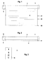
- the Figures 1 and 2 schematically show the structure of a shading device 1.
- the shading device 1 may generally be a sun protection device such as a roller blind, a screen or the like.
- the term shading device 1 also includes units such as shutters and the like.
- the shading device 1 has a curtain 2, which is up on a shaft 3 and unrolled and so can be extended and retracted.
- the procedure 2 of the curtain 2 via a drive 4, which consists in a known manner of an electric motor and a control unit for controlling the electric motor.
- FIG. 1 shows the shading device 1 with extended curtain 2
- FIG. 2 shows the shading device 1 with retracted curtain 2.
- retracted curtain 2 this is in an open position, corresponding to a first end position, the in FIG. 2 is defined by the position of the lower edge of the curtain 2 and denoted by E1.
- extended curtain 2 this is in a closed position, corresponding to a second end position, the in FIG. 1 is defined by the position of the lower edge of the curtain 2 and is denoted by E2.
- a control element 5 For actuating the shading device 1, in particular for moving the curtain 2, a control element 5 is provided which in FIG. 3 is shown.
- the operating element 5 has a housing 5a, in which three keys are arranged operably. One key constitutes an up key 6, one key constitutes a down key 7, the third key forms a stop and acknowledge key 8.
- the communication between the operating element 5 and the drive 4 of the shading device 1 takes place in the present case without contact via a radio link.
- a radio transmitter 9 is arranged in the control element 5, which sends radio signals to a radio receiver 10 in the drive 4.
- bidirectional contactless data transmission could also be provided.
- a wired communication between the control element 5 and drive 4 may be provided.
- a processor not shown, may be provided which evaluates the key signals of the keys and which controls the radio transmitter 9.
- the curtain 2 In standard operation, the curtain 2 is moved between an open position and closed position, for which purpose the drive 4 is operated in a high-speed operation. In high-speed, the drive 4 is typically in the upper Operating limit of a speed.
- the up button 6 For retracting the curtain 2 in the open position, the up button 6 is briefly tapped by an operator.
- the down button 7 For retracting the blind in the closed position, the down button 7 is briefly tapped by an operator.
- FIG. 1 are two such intermediate positions with Z1, Z2, which denotes the corresponding positions of the lower edge of the blind marking.
- the operator performs a teach-in process.
- the curtain 2 is operated in a slow-speed, that is, the drive 4 is operated at a significantly lower speed than in high-speed.
- the speed in high-speed is typically a multiple of the speed in slow speed.
- the teach-in process can be started and performed in two different ways. If the curtain 2 is in its closed position, the teach-in process is triggered by continuous actuation of the up-button 6. The operator keeps the up button 6 pressed during the teaching process and observes the curtain 2 until, for example, the intermediate position Z1 is reached. Since in the teach-in process the curtain 2 is moved in slow motion, the operator can accurately track the travel of the curtain 2 and thus control the intermediate position Z1 accurately. If the intermediate position Z1 is reached, the operator additionally presses the stop and acknowledge button 8. By pressing the stop and acknowledge button 8, the curtain 2 stops in the intermediate position Z1. Stopping the curtain 2 is registered in the control unit. The intermediate position Z1 is then stored in the control unit.
- the drive 4 or the curtain 2 is preferably associated with a sensor whose signals determine the current hanging position. Preferably, these sensor signals are stored as a measure of the intermediate position Z1 in the control unit.
- This intermediate position Z1 is stored for the upward key 6.
- the deposit takes place automatically when learning the intermediate position Z1 by simultaneously pressing the keys up key 6 and stop and acknowledge key 8.
- a learning process can be started by permanently pressing the down key 7 from the opening position.
- the curtain 2 then runs in slow speed down.
- the operator depresses the stop and acknowledge key 8 in addition to the downwards key 7, as a result of which the intermediate position has been learned in the control unit and stored for the downwards key 7.
- the operator can optionally control one of the end positions or one of the intermediate positions Z1, Z2. If the operator wishes to move the curtain 2 into the opening position, she taps once briefly the button up button 6. If the operator wishes to move the curtain 2 into the closed position, she taps once briefly the button down button 7. The curtain 2 then runs at high speed in the open position or closed position. If the operator wishes to retract the curtain 2 into the intermediate position Z1, then it briefly actuates twice the key for which the intermediate position Z1 is stored, namely the up-button 6. The curtain 2 then runs at high speed into the intermediate position Z1.
- the operator If the operator wishes to move the curtain 2 into the intermediate position Z2, then it briefly actuates twice the key for which the intermediate position Z2 is stored, namely the down key 7. The curtain 2 then runs at high speed into the intermediate position Z2.
- a specific key combination is preferably provided. If the operator wishes to delete the intermediate position stored for the up-key 6, it operates the up-key 6 and the stop-and-release key 8 simultaneously. If the operator wishes to put down the intermediate position for the down key 7 delete, press the down button 7 and stop and acknowledge button 8 simultaneously.
- the deposited for the up-button 6 or down button 7 intermediate position can be deleted by a new training process is started and for the up-button 6 and down button 7, a new intermediate position is learned, so that the previous intermediate position overwritten becomes.
Landscapes
- Engineering & Computer Science (AREA)
- Structural Engineering (AREA)
- Architecture (AREA)
- Civil Engineering (AREA)
- Operating, Guiding And Securing Of Roll- Type Closing Members (AREA)
- Curtains And Furnishings For Windows Or Doors (AREA)
- Blinds (AREA)
Abstract
Description
- Die Erfindung betrifft eine Beschattungsvorrichtung gemäß dem Oberbegriff des Anspruchs 1.
- Beschattungsvorrichtungen im Sinne der vorliegenden Erfindung können generell in Form von Sonnenschutzvorrichtungen wie Rollos ausgebildet sein. Generell sind mit diesen Beschattungsvorrichtungen auch Rollläden und dergleichen umfasst. Weiterhin können derartige Beschattungsvorrichtungen für Applikationen wie Rauch- und Wärmeschutzanlagen eingesetzt werden.
- Generell weisen derartige Beschattungsvorrichtungen einen Behang auf, der mittels eines Antriebs angetrieben ist und so verfahren werden kann. Generell kann dabei der Behang in eine erste Endposition eingefahren werden, das heißt in dieser ersten Endposition ist der Behang auf einer Welle oder dergleichen aufgewickelt und befindet sich so in einer Öffnungsposition, in der er eine Türöffnung, ein Fenster oder ein sonstiges Gebäudeelement freigibt. Weiterhin kann der Behang in eine zweite Endposition ausgefahren werden, das heißt in dieser zweiten Endposition ist der Behang von der Welle oder dergleichen abgewickelt und befindet sich in einer Schließposition, in der er eine Türöffnung, ein Fenster oder ein sonstiges Gebäudeelement abdeckt.
- Bei bekannten Beschattungsvorrichtungen erfolgt bei automatisierter Betätigung stets ein Wechsel zwischen der Schließ- und Öffnungsposition, das heißt durch Betätigen eines Bedienelements wird der Behang von der Öffnungsposition in die Schließposition oder umgekehrt eingefahren. Damit die Zeitdauer dieser Verfahrvorgänge möglichst kurz ist, wird der Antrieb zur Betätigung des Behangs in einem Schnelllauf bei hoher Drehzahl betrieben.
- Möchte eine Bedienperson den Behang in einer Zwischenstellung zwischen den beiden Endpositionen anhalten, kann sie dies durch Betätigen des Bedienelements tun. Die Bedienperson wartet prinzipiell, bis der Behang in die gewünschte Zwischenposition eingefahren ist und stoppt dann den Antrieb. Aufgrund der hohen Geschwindigkeit des Behangs ist jedoch das korrekte Anvisieren der Zwischenstellung für die Bedienperson nahezu unmöglich. Insbesondere ist es nicht möglich eine bestimmte Zwischenstellung mehrfach reproduziert anzufahren.
- Der Erfindung liegt die Aufgabe zugrunde, eine Beschattungsvorrichtung mit erweiterter Funktionalität bereitzustellen.
- Zur Lösung dieser Aufgabe sind die Merkmale des Anspruchs 1 vorgesehen. Vorteilhafte Ausführungsformen und zweckmäßige Weiterbildungen der Erfindung sind in den Unteransprüchen beschrieben.
- Die erfindungsgemäße Beschattungsvorrichtung umfasst einen von einem Antrieb angetriebenen Behang und ein dem Antrieb zugeordnetes Bedienelement. Der Behang ist in eine erste Endposition einfahrbar und in eine zweite Endposition ausfahrbar. Durch Betätigungen des Bedienelements ist der Behang wahlweise in einem Schnelllauf oder Langsamlauf verfahrbar. Während des Langsamlaufs ist wenigstens eine Zwischenposition des Behangs einlernbar, indem bei in der Zwischenposition befindlicher Behang das Bedienelement betätigt wird. Nach erfolgtem Einlernen der Zwischenposition ist durch spezifisches Betätigen des Bedienelements wahlweise eine der Endpositionen oder die eingelernte Zwischenposition mit dem Behang anfahrbar.
- Bei der erfindungsgemäßen Beschattungsvorrichtung wird der Behang jeweils im Schnelllauf in die erste und zweite Endposition, das heißt in seine Öffnungs- und Schließposition eingefahren. Durch den Betrieb des Antriebs im Schnelllauf kann dabei die Öffnungsposition beziehungsweise Schließposition schnell angefahren werden, was einen vom Benutzer gewünschten Bedienkomfort darstellt.
- Ein wesentlicher Vorteil der Erfindung besteht darin, dass der Behang nicht nur die beiden Endpositionen anfahren kann, sondern gezielt und reproduzierbar auch eine oder mehrere Zwischenpositionen, die in einem Einlernvorgang zuvor eingelernt worden sind. Wesentlich hierbei ist, dass in dem jeweiligen Einlernvorgang der Behang in einem Langsamlauf verfahren wird, wobei die Geschwindigkeit des Behangs im Langsamlauf gegenüber der Geschwindigkeit im Schnelllauf deutlich reduziert ist. Eine Bedienperson, die den Einlernvorgang überwacht, kann durch das langsame Verfahren des Behangs im Langsamlauf die einzustellende Zwischenposition sehr genau anvisieren und dann durch Betätigen des Bedienelements auswählen. Nachdem die Bedienperson die Zwischenposition eingelernt hat, kann diese jederzeit durch ein erneutes, spezifisches Betätigen des Bedienelements angefahren werden. Die Zwischenposition ist somit exakt vorgegeben und kann reproduzierbar mehrfach mit dem Behang angefahren werden.
- Wenn eine eingelernte Zwischenposition für den Betrieb der Beschattungsvorrichtung nicht mehr benötigt wird, kann diese vorteilhaft durch ein spezifisches Betätigen des Bedienelements gelöscht werden.
- Alternativ ist eine eingelernte Zwischenposition durch Einlernen einer neuen Zwischenposition überschreibbar.
- Beide Varianten gewährleisten einen flexiblen, bedienerfreundlichen Betrieb der erfindungsgemäßen Beschattungsvorrichtung, da Zwischenpositionen gleichermaßen einfach eingelernt und wieder gelöscht werden können.
- Die Funktionalität der erfindungsgemäßen Beschattungsvorrichtung kann dadurch erweitert werden, dass mit den Einlernvorgängen nicht nur frei wählbare Zwischenpositionen zwischen den beiden Endpositionen, sondern auch die Endpositionen selbst eingelernt werden können.
- Eine weitere Erhöhung der Funktionalität der erfindungsgemäßen Beschattungsvorrichtung wird dadurch erzielt, dass in einer eingelernten Zwischenposition eine spezifische Behangfunktion aktivierbar ist.
- Ist die Beschattungsvorrichtung beispielsweise in Form einer Sonnenschutzvorrichtung wie z. B. einem Rollo ausgebildet, kann in der Zwischenposition selbsttätig oder durch aktives Betätigen des Bedienelements ein Jalousieren des Behangs ausgelöst werden. Ist die Beschattungsvorrichtung beispielsweise als Screen ausgebildet, so kann die Behangfunktion in einem Spannen des Stoffs des Behangs, beispielsweise durch einen Einrastvorgang, bestehen.
- Gemäß einer vorteilhaften Ausgestaltung der Erfindung weist das Bedienelement eine Anzahl von Tasten auf, wobei für eine Taste jeweils eine Zwischenposition einlernbar ist.
- Zweckmäßigerweise ist für das Einlernen einer Zwischenposition für eine Taste diese Taste allein oder in Kombination mit einer weiteren Taste betätigt. Die eingelernte Zwischenposition ist für die jeweilige Taste hinterlegt, so dass durch spezifisches Betätigen dieser Taste diese Zwischenposition des Behangs anfahrbar ist.
- Das mit einem Tastenfeld ausgestaltete Bedienelement weist einen besonders einfachen, robusten und kostengünstigen Aufbau auf. Die Tastenbedienung ist dabei für eine Bedienperson einfach durchführbar.
- Durch die Hinterlegung der Zwischenposition auf einzelne Tasten des Bedienelements sind diese für eine Bedienperson leicht auffindbar. Ebenso können die Zwischenpositionen durch Betätigen der jeweiligen Tasten einfach eingelernt und bei Bedarf abgerufen werden.
- In einer alternativen Ausführungsform ist als Bedienelement eine Anzeige- und Eingabeeinheit vorgesehen.
- Ein derartiges Bedienelement eignet sich besonders für komplexere Anwendungen, wenn eine größere Anzahl von Zwischenpositionen eingelernt werden soll.
- Besonders vorteilhaft erfolgt zwischen Bedienelement und Antrieb eine berührungslose Datenübertragung. Insbesondere erfolgt die berührungslose Datenübertragung durch Senden und Empfangen von Funksignalen.
- Das Bedienelement ist somit von den weiteren Komponenten der Beschattungsvorrichtung räumlich weitgehend unabhängig einsetzbar.
- Alternativ erfolgt zwischen Bedienelement und Antrieb eine kabelgebundene Datenübertragung.
- Die Erfindung wird im Folgenden anhand der Zeichnungen erläutert. Es zeigen:
- Figur 1:
- Ausführungsbeispiel einer Beschattungsvorrichtung mit ausgefahrenem Behang.
- Figur 2:
- Beschattungsvorrichtung
Figur 1 bei eingefahrenem Behang. - Figur 3:
- Bedienelement für die Beschattungsvorrichtung gemäß
Figur 1 . - Die
Figuren 1 und 2 zeigen schematisch den Aufbau einer Beschattungsvorrichtung 1. Die Beschattungsvorrichtung 1 kann generell eine Sonnenschutzvorrichtung wie ein Rollo, ein Screen oder dergleichen sein. Generell umfasst der Begriff Beschattungsvorrichtung 1 auch Einheiten wie Rollläden und dergleichen. - Die Beschattungsvorrichtung 1 weist einen Behang 2 auf, der auf einer Welle 3 auf- und abrollbar ist und so ein- und ausgefahren werden kann. Das Verfahren des Behangs 2 erfolgt über einen Antrieb 4, der in bekannter Weise aus einem Elektromotor und einer Steuereinheit zur Steuerung des Elektromotors besteht.
-
Figur 1 zeigt die Beschattungsvorrichtung 1 bei ausgefahrenem Behang 2,Figur 2 zeigt die Beschattungsvorrichtung 1 bei eingefahrenem Behang 2. Bei eingefahrenem Behang 2 befindet sich dieser in einer Öffnungsposition, entsprechend einer ersten Endposition, die inFigur 2 durch die Position der Unterkante des Behangs 2 definiert und mit E1 bezeichnet ist. Bei ausgefahrenem Behang 2 befindet sich dieser in einer Schließposition, entsprechend einer zweiten Endposition, die inFigur 1 durch die Position der Unterkante des Behangs 2 definiert und mit E2 bezeichnet ist. - Zur Betätigung der Beschattungsvorrichtung 1, insbesondere zum Verfahren des Behangs 2, ist ein Bedienelement 5 vorgesehen, das in
Figur 3 dargestellt ist. Das Bedienelement 5 weist ein Gehäuse 5a auf, in welchem drei Tasten betätigbar angeordnet sind. Eine Taste bildet eine Aufwärts-Taste 6, eine Taste bildet eine Abwärts-Taste 7, die dritte Taste bildet eine Stopp- und Quittiertaste 8. - Die Kommunikation zwischen dem Bedienelement 5 und dem Antrieb 4 der Beschattungsvorrichtung 1 erfolgt im vorliegenden Fall berührungslos über eine Funkverbindung. Hierzu ist im Bedienelement 5 ein Funksender 9 angeordnet, der Funksignale an einen Funkempfänger 10 im Antrieb 4 sendet. Prinzipiell könnte auch eine bidirektionale berührungslose Datenübertragung vorgesehen sein. Alternativ kann auch eine kabelgebundene Kommunikation zwischen dem Bedienelement 5 und Antrieb 4 vorgesehen sein.
- Im Bedienelement 5 kann ein nicht dargestellter Prozessor vorgesehen sein, der die Tastensignale der Tasten auswertet und der den Funksender 9 ansteuert.
- Im Standard-Betrieb wird der Behang 2 zwischen einer Öffnungsposition und Schließposition verfahren, wobei hierzu der Antrieb 4 in einem Schnelllauf betrieben wird. Im Schnelllauf wird der Antrieb 4 typischerweise im oberen Grenzbereich einer Drehzahl betrieben. Zum Einfahren des Behangs 2 in die Öffnungsposition wird von einer Bedienperson die Aufwärts-Taste 6 kurz angetippt. Zum Einfahren des Behangs in die Schließposition wird von einer Bedienperson die Abwärts-Taste 7 kurz angetippt.
- Je nach Applikation kann es für die Bedienperson wünschenswert sein, generell spezifische Zwischenpositionen des Behangs 2 anzufahren. In
Figur 1 sind zwei solche Zwischenpositionen mit Z1, Z2, die die entsprechenden Stellungen der Unterkante des Behangsmarkieren, bezeichnet. - Zur genauen Einstellung der Zwischenpositionen Z1, Z2 führt die Bedienperson jeweils einen Einlernvorgang aus. Während eines Einlernvorgangs wird der Behang 2 in einem Langsamlauf betrieben, das heißt der Antrieb 4 wird mit einer erheblich geringeren Drehzahl als im Schnelllauf betrieben. Die Drehzahl im Schnelllauf beträgt typisch ein Mehrfaches der Drehzahl im Langsamlauf.
- Im vorliegenden Ausführungsbeispiel kann der Einlernvorgang auf zwei unterschiedliche Weisen gestartet und durchgeführt werden. Befindet sich der Behang 2 in seiner Schließposition, so wird der Einlernvorgang durch dauerndes Betätigen der Aufwärts-Taste 6 ausgelöst. Die Bedienperson hält während des Einlernvorgangs die Aufwärts-Taste 6 betätigt und beobachtet den Behang 2, bis beispielsweise die Zwischenposition Z1 erreicht ist. Da im Einlernvorgang der Behang 2 im Langsamlauf bewegt wird, kann die Bedienperson den Verfahrweg des Behangs 2 genau verfolgen und so die Zwischenposition Z1 genau ansteuern. Ist die Zwischenposition Z1 erreicht, drückt die Bedienperson zusätzlich die Stopp- und Quittiertaste 8. Durch das Drücken der Stopp- und Quittiertaste 8 stoppt der Behang 2 in der Zwischenposition Z1. Das Stoppen des Behangs 2 wird in der Steuereinheit registriert. Die Zwischenposition Z1 wird dann in der Steuereinheit abgespeichert. Bevorzugt ist dem Antrieb 4 oder dem Behang 2 ein Sensor zugeordnet, durch dessen Signale die aktuelle Behangposition bestimmt ist. Vorzugsweise werden diese Sensorsignale als Maß für die Zwischenposition Z1 in der Steuereinheit abgespeichert.
- Diese Zwischenposition Z1 wird für die Aufwärts-Taste 6 hinterlegt. Die Hinterlegung erfolgt selbsttätig beim Einlernen der Zwischenposition Z1 durch gleichzeitiges Drücken der Tasten Aufwärts-Taste 6 und Stopp- und Quittiertaste 8.
- In analoger Weise kann aus der Öffnungsposition heraus ein Einlernvorgang durch dauerhaftes Betätigen der Abwärts-Taste 7 gestartet werden. Der Behang 2 läuft dann im Langsamlauf abwärts. Sobald die Zwischenposition Z2 erreicht ist, drückt die Bedienperson zusätzlich zur Abwärts-Taste 7 die Taste Stopp-und Quittiertaste 8, wodurch die Zwischenposition in der Steuereinheit eingelernt und für die Abwärts-Taste 7 hinterlegt ist.
- Nach Beenden der Einlernvorgänge kann die Bedienperson wahlweise eine der Endpositionen oder eine der Zwischenpositionen Z1, Z2 ansteuern. Möchte die Bedienperson den Behang 2 in die Öffnungsposition einfahren, tippt sie einmal kurz die Taste Aufwärts-Taste 6 an. Möchte die Bedienperson den Behang 2 in die Schließposition einfahren, tippt sie einmal kurz die Taste Abwärts-Taste 7 an. Der Behang 2 läuft dann im Schnelllauf in die Öffnungsposition beziehungsweise Schließposition. Möchte die Bedienperson den Behang 2 in die Zwischenposition Z1 einfahren, so betätigt sie zweimal kurz die Taste für die die Zwischenposition Z1 hinterlegt ist, nämlich die Aufwärts-Taste 6. Der Behang 2 läuft dann im Schnelllauf in die Zwischenposition Z1 ein.
- Möchte die Bedienperson den Behang 2 in die Zwischenposition Z2 einfahren, so betätigt sie zweimal kurz die Taste für die die Zwischenposition Z2 hinterlegt ist, nämlich die Abwärts-Taste 7. Der Behang 2 läuft dann im Schnelllauf in die Zwischenposition Z2 ein.
- Zum Löschen einer Zwischenposition, die für eine Taste hinterlegt ist, ist bevorzugt eine bestimmte Tastenkombination vorgesehen. Möchte die Bedienperson die für die Aufwärts-Taste 6 hinterlegte Zwischenposition löschen, betätigt sie die Aufwärts-Taste 6 und Stopp- und Quittiertaste 8 gleichzeitig. Möchte die Bedienperson die für die Abwärts-Taste 7 hinlegte Zwischenposition löschen, betätigt sie die Abwärts-Taste 7 und Stopp- und Quittiertaste 8 gleichzeitig.
- Weiterhin kann die für die Aufwärts-Taste 6 oder Abwärts-Taste 7 hinterlegte Zwischenposition dadurch gelöscht werden, dass ein neuer Einlernvorgang gestartet wird und für die Aufwärts-Taste 6 und Abwärts-Taste 7 eine neue Zwischenposition eingelernt wird, so dass die bisherige Zwischenposition überschrieben wird.
-
- (1)
- Beschattungsvorrichtung
- (2)
- Behang
- (3)
- Welle
- (4)
- Antrieb
- (5)
- Bedienelement
- (5a)
- Gehäuse
- (6)
- Aufwärts-Taste
- (7)
- Abwärts-Taste
- (8)
- Stopp- und Quittiertaste
- (9)
- Funksender
- (10)
- Funkempfänger
Claims (15)
- Beschattungsvorrichtung (1) mit einem von einem Antrieb (4) angetriebenen Behang (2) und einem dem Antrieb (4) zugeordneten Bedienelement (5), wobei der Behang (2) in eine erste Endposition einfahrbar und in eine zweite Endposition ausfahrbar ist, dadurch gekennzeichnet, dass durch Betätigungen des Bedienelements (5) der Behang (2) wahlweise in einem Schnelllauf oder Langsamlauf verfahrbar ist, dass während des Langsamlaufs wenigstens eine Zwischenposition des Behangs (2) einlernbar ist, indem bei in der Zwischenposition befindlichen Behang (2) das Bedienelement (5) betätigt wird, und dass nach erfolgtem Einlernen der Zwischenposition durch spezifisches Betätigen des Bedienelements (5) wahlweise eine der Endpositionen oder die eingelernte Zwischenposition mit dem Behang (2) anfahrbar ist.
- Beschattungsvorrichtung nach Anspruch 1, dadurch gekennzeichnet, dass eine eingelernte Zwischenposition durch spezifisches Betätigen des Bedienelements (5) löschbar ist.
- Beschattungsvorrichtung nach Anspruch 1, dadurch gekennzeichnet, dass eine eingelernte Zwischenposition durch Einlernen einer neuen Zwischenposition überschreibbar ist.
- Beschattungsvorrichtung nach einem der Ansprüche 1 bis 3, dadurch gekennzeichnet, dass die oder jede Zwischenposition eine Endposition ist.
- Beschattungsvorrichtung nach einem der Ansprüche 1 bis 4, dadurch gekennzeichnet, dass in einer eingelernten Zwischenposition eine spezifische Behangfunktion aktivierbar ist.
- Beschattungsvorrichtung nach einem der Ansprüche 1 bis 5, dadurch gekennzeichnet, dass das Bedienelement (5) eine Anzahl von Tasten aufweist, wobei für eine Taste jeweils eine Zwischenposition einlernbar ist.
- Beschattungsvorrichtung nach Anspruch 6, dadurch gekennzeichnet, dass für das Einlernen einer Zwischenposition für eine Taste diese Taste allein oder in Kombination mit einer weiteren Taste betätigt ist.
- Beschattungsvorrichtung nach einem der Ansprüche 6 oder 7, dadurch gekennzeichnet, dass die eingelernte Zwischenposition für die jeweilige Taste hinterlegt ist, so dass durch spezifisches Betätigen dieser Taste diese Zwischenposition des Behangs (2) anfahrbar ist.
- Beschattungsvorrichtung nach einem der Ansprüche 6 bis 8, dadurch gekennzeichnet, dass das Bedienelement (5) eine Aufwärts-Taste (6) zur Aktivierung der Einfahrbewegung des Behangs (2), eine Abwärts-Taste (7) zur Aktivierung der Ausfahrbewegung des Behangs (2) sowie eine Stopp-und Quittiertaste (8) aufweist.
- Beschattungsvorrichtung nach Anspruch 9, dadurch gekennzeichnet, dass für die Aufwärts-Taste (6) und Abwärts-Taste (7) jeweils eine Zwischenposition einlernbar ist.
- Beschattungsvorrichtung nach einem der Ansprüche 9 oder 10, dadurch gekennzeichnet, dass bei kurzzeitiger Betätigung der Aufwärts-Taste (6) oder der Abwärts-Taste (7) der Behang (2) im Schnelllauf verfahren wird, und dass bei dauerhafter Betätigung der Aufwärts-Taste (6) oder der Abwärts-Taste (7) der Behang (2) im Langsamlauf verfahren wird.
- Beschattungsvorrichtung nach Anspruch 11, dadurch gekennzeichnet, dass bei betätigter Aufwärts-Taste (6) oder Abwärts-Taste (7) und bei im Langsamlauf verfahrenden Behang (2) in einer gewünschten Position des Behangs (2) zusätzlich die Stopp- und Quittiertaste (8) betätigt wird, wodurch diese Position als Zwischenposition eingelernt ist.
- Beschattungsvorrichtung nach einem der Ansprüche 1 bis 5, dadurch gekennzeichnet, dass als Bedienelement (5) eine Anzeige- und Eingabeeinheit vorgesehen ist.
- Beschattungsvorrichtung nach einem der Ansprüche 1 bis 13, dadurch gekennzeichnet, dass zwischen Bedienelement (5) und Antrieb (4) eine berührungslose oder kabelgebundene Datenübertragung erfolgt.
- Beschattungsvorrichtung nach Anspruch 14, dadurch gekennzeichnet, dass die berührungslose Datenübertragung durch Senden und Empfangen von Funksignalen erfolgt.
Priority Applications (1)
| Application Number | Priority Date | Filing Date | Title |
|---|---|---|---|
| PL11195075T PL2476859T3 (pl) | 2011-01-13 | 2011-12-22 | Urządzenie do zacieniania |
Applications Claiming Priority (1)
| Application Number | Priority Date | Filing Date | Title |
|---|---|---|---|
| DE202011001437U DE202011001437U1 (de) | 2011-01-13 | 2011-01-13 | Beschattungsvorrichtung |
Publications (3)
| Publication Number | Publication Date |
|---|---|
| EP2476859A2 true EP2476859A2 (de) | 2012-07-18 |
| EP2476859A3 EP2476859A3 (de) | 2015-01-21 |
| EP2476859B1 EP2476859B1 (de) | 2018-10-03 |
Family
ID=43799328
Family Applications (1)
| Application Number | Title | Priority Date | Filing Date |
|---|---|---|---|
| EP11195075.4A Active EP2476859B1 (de) | 2011-01-13 | 2011-12-22 | Beschattungsvorrichtung |
Country Status (3)
| Country | Link |
|---|---|
| EP (1) | EP2476859B1 (de) |
| DE (1) | DE202011001437U1 (de) |
| PL (1) | PL2476859T3 (de) |
Cited By (3)
| Publication number | Priority date | Publication date | Assignee | Title |
|---|---|---|---|---|
| WO2015017842A3 (en) * | 2013-08-02 | 2015-04-23 | Lutron Electronics Co., Inc. | Motorized sheer shading system |
| US9347261B2 (en) | 2013-08-02 | 2016-05-24 | Lutron Electronics Co., Inc. | Adjustment mechanisms for shades |
| EP3783190A3 (de) * | 2019-08-16 | 2021-03-10 | Ningbo Sunfree Motor Technology Company Limited | Vorrichtung zur fernsteuerung eines vorhangs und ein verfahren zur einstellung von deren fernsteuerungshub |
Families Citing this family (3)
| Publication number | Priority date | Publication date | Assignee | Title |
|---|---|---|---|---|
| TWI535402B (zh) * | 2014-01-03 | 2016-06-01 | 德侑股份有限公司 | 電動窗簾及其操作方法 |
| DE202019104452U1 (de) * | 2019-08-13 | 2020-12-01 | Elero Gmbh | Beschattungsanlage |
| US11686151B2 (en) | 2020-12-31 | 2023-06-27 | Springs Window Fashions, Llc | Motorized shade and wand assembly |
Family Cites Families (9)
| Publication number | Priority date | Publication date | Assignee | Title |
|---|---|---|---|---|
| US5170108A (en) * | 1991-01-31 | 1992-12-08 | Daylighting, Inc. | Motion control method and apparatus for motorized window blinds and and the like |
| FR2767860B1 (fr) * | 1997-08-27 | 1999-10-29 | Franck Cieslik | Agencement de commande de fin de course d'un volet ou store de fermeture d'une ouverture tel qu'une porte ou fenetre |
| US6082433A (en) * | 1997-11-21 | 2000-07-04 | Overhead Door Corporation | Control system and method for roll-up door |
| DE19809594B4 (de) * | 1998-03-06 | 2004-08-19 | Hans Arnhold | Rollladensteuerung |
| FR2803621B1 (fr) * | 2000-01-11 | 2002-03-22 | Jouvence | Installation de manoeuvre d'au moins un volet roulant |
| DE10138411A1 (de) * | 2001-08-04 | 2003-02-27 | Theben Ag | Positionsansteuerung von Jalousieantrieben |
| DE10209292C1 (de) * | 2002-03-01 | 2003-11-13 | Stehle & Soehne Ag J | Verfahren zur Einstellung zumindest einer flexiblen Endposition bei einer Jalousie |
| FR2863647B1 (fr) * | 2003-12-12 | 2006-02-24 | Somfy | Procede d'apprentissage pour la commande d'un ecran motorise a lames orientables et dispositif pour sa mise en oeuvre |
| US7982422B2 (en) * | 2006-01-19 | 2011-07-19 | Hunter Douglas Inc. | Push button control for motorized coverings with light control |
-
2011
- 2011-01-13 DE DE202011001437U patent/DE202011001437U1/de not_active Expired - Lifetime
- 2011-12-22 EP EP11195075.4A patent/EP2476859B1/de active Active
- 2011-12-22 PL PL11195075T patent/PL2476859T3/pl unknown
Non-Patent Citations (1)
| Title |
|---|
| None |
Cited By (7)
| Publication number | Priority date | Publication date | Assignee | Title |
|---|---|---|---|---|
| WO2015017842A3 (en) * | 2013-08-02 | 2015-04-23 | Lutron Electronics Co., Inc. | Motorized sheer shading system |
| US9347261B2 (en) | 2013-08-02 | 2016-05-24 | Lutron Electronics Co., Inc. | Adjustment mechanisms for shades |
| US9611689B2 (en) | 2013-08-02 | 2017-04-04 | Lutron Electronics Co., Inc. | Motorized sheer shading system |
| US10570661B2 (en) | 2013-08-02 | 2020-02-25 | Lutron Technology Company Llc | Motorized sheer shading system |
| US11725454B2 (en) | 2013-08-02 | 2023-08-15 | Lutron Technology Company Llc | Motorized sheer shading system |
| US12553282B2 (en) | 2013-08-02 | 2026-02-17 | Lutron Technology Company Llc | Motorized sheer shading system |
| EP3783190A3 (de) * | 2019-08-16 | 2021-03-10 | Ningbo Sunfree Motor Technology Company Limited | Vorrichtung zur fernsteuerung eines vorhangs und ein verfahren zur einstellung von deren fernsteuerungshub |
Also Published As
| Publication number | Publication date |
|---|---|
| DE202011001437U1 (de) | 2011-03-17 |
| EP2476859A3 (de) | 2015-01-21 |
| EP2476859B1 (de) | 2018-10-03 |
| PL2476859T3 (pl) | 2019-03-29 |
Similar Documents
| Publication | Publication Date | Title |
|---|---|---|
| EP2476859A2 (de) | Beschattungsvorrichtung | |
| DE102010024776B4 (de) | Vorrichtung zur Bedienung mehrerer Funktionen in einem Kraftfahrzeug | |
| EP1129871B2 (de) | Scheibenrollo-Vorrichtung für Fahrzeugscheiben | |
| DE602005001488T2 (de) | Motorgetriebener Schirm und Verfahren zu seiner Betätigung | |
| DE102011119579A1 (de) | Vorrichtung zur elektromotorischen Betätigung einer Tür | |
| DE102013203930A1 (de) | Verfahren und Vorrichtung zur Steuerung eines Elektrogeräts | |
| DE102014111921A1 (de) | Verstellsystem zum Verstellen einer Komponente eines Kraftfahrzeugs auf einem Verstellweg | |
| EP3240936B1 (de) | Verfahren zum betreiben eines türantriebs, türantriebssteuerung, türantrieb und drehflügeltür | |
| DE102010014806B4 (de) | Torantriebsvorrichtung, damit versehener Gebäudeabschluss, Torsystem und Herstell- und Antriebsverfahren | |
| DE69218927T2 (de) | Verfahren zur Steuerung eines mobilen Teils einer Betriebseinrichtung und Betriebseinrichtung zu dieser Realisierung | |
| DE4208426A1 (de) | Verfahren zum steuern von torantrieben und vorrichtung hierfuer | |
| DE10212006B4 (de) | Steuerschaltung zum Betätigen eines öffnungsfähigen Fahrzeugdachs | |
| DE19733405A1 (de) | Fernsteuerungsvorrichtung zur drahtlosen Betätigung von Antriebsvorrichtungen für Tore, Türen, Fenster, Markisen oder dergleichen | |
| DE19831119C2 (de) | Garagentorantrieb | |
| DE60130400T2 (de) | Steuerung für motorisierte Verdunkelungsvorrichtungen mit Programmwahl | |
| DE4200092A1 (de) | Verfahren zur steuerung eines antriebes, insbesondere eines torantriebes und antrieb zur durchfuehrung des verfahrens | |
| DE102015104825C5 (de) | Verfahren zum Betreiben eines Türantriebs, Türantriebssteuerung, Türantrieb und Drehflügeltür | |
| WO2016113367A1 (de) | Verfahren zum betreiben eines türantriebs, türantriebssteuerung, türantrieb und drehflügeltür | |
| DE4337745C2 (de) | Bedienelement für ein Schiebe-Hebedach mit mehreren Deckeln | |
| DE102014018455A1 (de) | Verfahren zum Steuern einer Funktionseinrichtung zum flächigen Abschirmen eines Bereichs des Kraftfahrzeugs | |
| DE202011051474U1 (de) | Antriebssystem für ein Tor | |
| DE202010007687U1 (de) | Bedienungsvorrichtung, insbesondere für einen motorisch angetriebenen Rollladen | |
| EP1913222B1 (de) | Verfahren zur positionierung einer beweglichen einheit in einem kraftfahrzeug | |
| EP2589729B1 (de) | Garagentorgriff mit elektrischem Signalgeber zum Betätigen eines Seiten-Sektionaltores | |
| EP0657795A2 (de) | Vorrichtung zur Steuerung von beweglichen Einrichtungen wie Rolltoren od. dgl. |
Legal Events
| Date | Code | Title | Description |
|---|---|---|---|
| PUAI | Public reference made under article 153(3) epc to a published international application that has entered the european phase |
Free format text: ORIGINAL CODE: 0009012 |
|
| AK | Designated contracting states |
Kind code of ref document: A2 Designated state(s): AL AT BE BG CH CY CZ DE DK EE ES FI FR GB GR HR HU IE IS IT LI LT LU LV MC MK MT NL NO PL PT RO RS SE SI SK SM TR |
|
| AX | Request for extension of the european patent |
Extension state: BA ME |
|
| PUAL | Search report despatched |
Free format text: ORIGINAL CODE: 0009013 |
|
| AK | Designated contracting states |
Kind code of ref document: A3 Designated state(s): AL AT BE BG CH CY CZ DE DK EE ES FI FR GB GR HR HU IE IS IT LI LT LU LV MC MK MT NL NO PL PT RO RS SE SI SK SM TR |
|
| AX | Request for extension of the european patent |
Extension state: BA ME |
|
| RIC1 | Information provided on ipc code assigned before grant |
Ipc: E06B 9/90 20060101AFI20141216BHEP |
|
| 17P | Request for examination filed |
Effective date: 20150209 |
|
| RBV | Designated contracting states (corrected) |
Designated state(s): AL AT BE BG CH CY CZ DE DK EE ES FI FR GB GR HR HU IE IS IT LI LT LU LV MC MK MT NL NO PL PT RO RS SE SI SK SM TR |
|
| STAA | Information on the status of an ep patent application or granted ep patent |
Free format text: STATUS: EXAMINATION IS IN PROGRESS |
|
| 17Q | First examination report despatched |
Effective date: 20170920 |
|
| REG | Reference to a national code |
Ref country code: DE Ref legal event code: R079 Ref document number: 502011014789 Country of ref document: DE Free format text: PREVIOUS MAIN CLASS: E06B0009900000 Ipc: E06B0009680000 |
|
| RIC1 | Information provided on ipc code assigned before grant |
Ipc: E06B 9/90 20060101ALI20180424BHEP Ipc: E06B 9/68 20060101AFI20180424BHEP |
|
| GRAP | Despatch of communication of intention to grant a patent |
Free format text: ORIGINAL CODE: EPIDOSNIGR1 |
|
| STAA | Information on the status of an ep patent application or granted ep patent |
Free format text: STATUS: GRANT OF PATENT IS INTENDED |
|
| INTG | Intention to grant announced |
Effective date: 20180604 |
|
| GRAS | Grant fee paid |
Free format text: ORIGINAL CODE: EPIDOSNIGR3 |
|
| GRAA | (expected) grant |
Free format text: ORIGINAL CODE: 0009210 |
|
| STAA | Information on the status of an ep patent application or granted ep patent |
Free format text: STATUS: THE PATENT HAS BEEN GRANTED |
|
| AK | Designated contracting states |
Kind code of ref document: B1 Designated state(s): AL AT BE BG CH CY CZ DE DK EE ES FI FR GB GR HR HU IE IS IT LI LT LU LV MC MK MT NL NO PL PT RO RS SE SI SK SM TR |
|
| REG | Reference to a national code |
Ref country code: GB Ref legal event code: FG4D Free format text: NOT ENGLISH |
|
| REG | Reference to a national code |
Ref country code: CH Ref legal event code: EP Ref country code: AT Ref legal event code: REF Ref document number: 1048783 Country of ref document: AT Kind code of ref document: T Effective date: 20181015 |
|
| REG | Reference to a national code |
Ref country code: DE Ref legal event code: R082 Ref document number: 502011014789 Country of ref document: DE Representative=s name: RUCKH, RAINER, DIPL.-PHYS. DR.RER.NAT., DE Ref country code: DE Ref legal event code: R081 Ref document number: 502011014789 Country of ref document: DE Owner name: ELERO GMBH, DE Free format text: FORMER OWNER: ELERO GMBH, 72660 BEUREN, DE |
|
| REG | Reference to a national code |
Ref country code: CH Ref legal event code: NV Representative=s name: ROTTMANN, ZIMMERMANN + PARTNER AG, CH Ref country code: DE Ref legal event code: R096 Ref document number: 502011014789 Country of ref document: DE Ref country code: IE Ref legal event code: FG4D Free format text: LANGUAGE OF EP DOCUMENT: GERMAN |
|
| RAP2 | Party data changed (patent owner data changed or rights of a patent transferred) |
Owner name: ELERO GMBH |
|
| REG | Reference to a national code |
Ref country code: NL Ref legal event code: MP Effective date: 20181003 |
|
| REG | Reference to a national code |
Ref country code: LT Ref legal event code: MG4D |
|
| PG25 | Lapsed in a contracting state [announced via postgrant information from national office to epo] |
Ref country code: NL Free format text: LAPSE BECAUSE OF FAILURE TO SUBMIT A TRANSLATION OF THE DESCRIPTION OR TO PAY THE FEE WITHIN THE PRESCRIBED TIME-LIMIT Effective date: 20181003 |
|
| PG25 | Lapsed in a contracting state [announced via postgrant information from national office to epo] |
Ref country code: CZ Free format text: LAPSE BECAUSE OF FAILURE TO SUBMIT A TRANSLATION OF THE DESCRIPTION OR TO PAY THE FEE WITHIN THE PRESCRIBED TIME-LIMIT Effective date: 20181003 Ref country code: NO Free format text: LAPSE BECAUSE OF FAILURE TO SUBMIT A TRANSLATION OF THE DESCRIPTION OR TO PAY THE FEE WITHIN THE PRESCRIBED TIME-LIMIT Effective date: 20190103 Ref country code: LT Free format text: LAPSE BECAUSE OF FAILURE TO SUBMIT A TRANSLATION OF THE DESCRIPTION OR TO PAY THE FEE WITHIN THE PRESCRIBED TIME-LIMIT Effective date: 20181003 Ref country code: FI Free format text: LAPSE BECAUSE OF FAILURE TO SUBMIT A TRANSLATION OF THE DESCRIPTION OR TO PAY THE FEE WITHIN THE PRESCRIBED TIME-LIMIT Effective date: 20181003 Ref country code: IS Free format text: LAPSE BECAUSE OF FAILURE TO SUBMIT A TRANSLATION OF THE DESCRIPTION OR TO PAY THE FEE WITHIN THE PRESCRIBED TIME-LIMIT Effective date: 20190203 Ref country code: LV Free format text: LAPSE BECAUSE OF FAILURE TO SUBMIT A TRANSLATION OF THE DESCRIPTION OR TO PAY THE FEE WITHIN THE PRESCRIBED TIME-LIMIT Effective date: 20181003 Ref country code: ES Free format text: LAPSE BECAUSE OF FAILURE TO SUBMIT A TRANSLATION OF THE DESCRIPTION OR TO PAY THE FEE WITHIN THE PRESCRIBED TIME-LIMIT Effective date: 20181003 Ref country code: BG Free format text: LAPSE BECAUSE OF FAILURE TO SUBMIT A TRANSLATION OF THE DESCRIPTION OR TO PAY THE FEE WITHIN THE PRESCRIBED TIME-LIMIT Effective date: 20190103 Ref country code: HR Free format text: LAPSE BECAUSE OF FAILURE TO SUBMIT A TRANSLATION OF THE DESCRIPTION OR TO PAY THE FEE WITHIN THE PRESCRIBED TIME-LIMIT Effective date: 20181003 |
|
| PG25 | Lapsed in a contracting state [announced via postgrant information from national office to epo] |
Ref country code: SE Free format text: LAPSE BECAUSE OF FAILURE TO SUBMIT A TRANSLATION OF THE DESCRIPTION OR TO PAY THE FEE WITHIN THE PRESCRIBED TIME-LIMIT Effective date: 20181003 Ref country code: PT Free format text: LAPSE BECAUSE OF FAILURE TO SUBMIT A TRANSLATION OF THE DESCRIPTION OR TO PAY THE FEE WITHIN THE PRESCRIBED TIME-LIMIT Effective date: 20190203 Ref country code: AL Free format text: LAPSE BECAUSE OF FAILURE TO SUBMIT A TRANSLATION OF THE DESCRIPTION OR TO PAY THE FEE WITHIN THE PRESCRIBED TIME-LIMIT Effective date: 20181003 Ref country code: GR Free format text: LAPSE BECAUSE OF FAILURE TO SUBMIT A TRANSLATION OF THE DESCRIPTION OR TO PAY THE FEE WITHIN THE PRESCRIBED TIME-LIMIT Effective date: 20190104 Ref country code: RS Free format text: LAPSE BECAUSE OF FAILURE TO SUBMIT A TRANSLATION OF THE DESCRIPTION OR TO PAY THE FEE WITHIN THE PRESCRIBED TIME-LIMIT Effective date: 20181003 |
|
| REG | Reference to a national code |
Ref country code: DE Ref legal event code: R097 Ref document number: 502011014789 Country of ref document: DE |
|
| PG25 | Lapsed in a contracting state [announced via postgrant information from national office to epo] |
Ref country code: DK Free format text: LAPSE BECAUSE OF FAILURE TO SUBMIT A TRANSLATION OF THE DESCRIPTION OR TO PAY THE FEE WITHIN THE PRESCRIBED TIME-LIMIT Effective date: 20181003 |
|
| PLBE | No opposition filed within time limit |
Free format text: ORIGINAL CODE: 0009261 |
|
| STAA | Information on the status of an ep patent application or granted ep patent |
Free format text: STATUS: NO OPPOSITION FILED WITHIN TIME LIMIT |
|
| PG25 | Lapsed in a contracting state [announced via postgrant information from national office to epo] |
Ref country code: SK Free format text: LAPSE BECAUSE OF FAILURE TO SUBMIT A TRANSLATION OF THE DESCRIPTION OR TO PAY THE FEE WITHIN THE PRESCRIBED TIME-LIMIT Effective date: 20181003 Ref country code: RO Free format text: LAPSE BECAUSE OF FAILURE TO SUBMIT A TRANSLATION OF THE DESCRIPTION OR TO PAY THE FEE WITHIN THE PRESCRIBED TIME-LIMIT Effective date: 20181003 Ref country code: EE Free format text: LAPSE BECAUSE OF FAILURE TO SUBMIT A TRANSLATION OF THE DESCRIPTION OR TO PAY THE FEE WITHIN THE PRESCRIBED TIME-LIMIT Effective date: 20181003 Ref country code: SM Free format text: LAPSE BECAUSE OF FAILURE TO SUBMIT A TRANSLATION OF THE DESCRIPTION OR TO PAY THE FEE WITHIN THE PRESCRIBED TIME-LIMIT Effective date: 20181003 Ref country code: MC Free format text: LAPSE BECAUSE OF FAILURE TO SUBMIT A TRANSLATION OF THE DESCRIPTION OR TO PAY THE FEE WITHIN THE PRESCRIBED TIME-LIMIT Effective date: 20181003 Ref country code: LU Free format text: LAPSE BECAUSE OF NON-PAYMENT OF DUE FEES Effective date: 20181222 |
|
| 26N | No opposition filed |
Effective date: 20190704 |
|
| REG | Reference to a national code |
Ref country code: IE Ref legal event code: MM4A |
|
| GBPC | Gb: european patent ceased through non-payment of renewal fee |
Effective date: 20190103 |
|
| REG | Reference to a national code |
Ref country code: BE Ref legal event code: MM Effective date: 20181231 |
|
| PG25 | Lapsed in a contracting state [announced via postgrant information from national office to epo] |
Ref country code: IE Free format text: LAPSE BECAUSE OF NON-PAYMENT OF DUE FEES Effective date: 20181222 Ref country code: SI Free format text: LAPSE BECAUSE OF FAILURE TO SUBMIT A TRANSLATION OF THE DESCRIPTION OR TO PAY THE FEE WITHIN THE PRESCRIBED TIME-LIMIT Effective date: 20181003 |
|
| PG25 | Lapsed in a contracting state [announced via postgrant information from national office to epo] |
Ref country code: BE Free format text: LAPSE BECAUSE OF NON-PAYMENT OF DUE FEES Effective date: 20181231 |
|
| PG25 | Lapsed in a contracting state [announced via postgrant information from national office to epo] |
Ref country code: GB Free format text: LAPSE BECAUSE OF NON-PAYMENT OF DUE FEES Effective date: 20190103 |
|
| PG25 | Lapsed in a contracting state [announced via postgrant information from national office to epo] |
Ref country code: MT Free format text: LAPSE BECAUSE OF FAILURE TO SUBMIT A TRANSLATION OF THE DESCRIPTION OR TO PAY THE FEE WITHIN THE PRESCRIBED TIME-LIMIT Effective date: 20181003 |
|
| PG25 | Lapsed in a contracting state [announced via postgrant information from national office to epo] |
Ref country code: TR Free format text: LAPSE BECAUSE OF FAILURE TO SUBMIT A TRANSLATION OF THE DESCRIPTION OR TO PAY THE FEE WITHIN THE PRESCRIBED TIME-LIMIT Effective date: 20181003 |
|
| PG25 | Lapsed in a contracting state [announced via postgrant information from national office to epo] |
Ref country code: MK Free format text: LAPSE BECAUSE OF NON-PAYMENT OF DUE FEES Effective date: 20181003 Ref country code: CY Free format text: LAPSE BECAUSE OF FAILURE TO SUBMIT A TRANSLATION OF THE DESCRIPTION OR TO PAY THE FEE WITHIN THE PRESCRIBED TIME-LIMIT Effective date: 20181003 Ref country code: HU Free format text: LAPSE BECAUSE OF FAILURE TO SUBMIT A TRANSLATION OF THE DESCRIPTION OR TO PAY THE FEE WITHIN THE PRESCRIBED TIME-LIMIT; INVALID AB INITIO Effective date: 20111222 |
|
| P01 | Opt-out of the competence of the unified patent court (upc) registered |
Free format text: CASE NUMBER: UPC_APP_0011462_2476859/2025 Effective date: 20251029 |
|
| REG | Reference to a national code |
Ref country code: CH Ref legal event code: U11 Free format text: ST27 STATUS EVENT CODE: U-0-0-U10-U11 (AS PROVIDED BY THE NATIONAL OFFICE) Effective date: 20260101 |
|
| PGFP | Annual fee paid to national office [announced via postgrant information from national office to epo] |
Ref country code: DE Payment date: 20250919 Year of fee payment: 15 |
|
| PGFP | Annual fee paid to national office [announced via postgrant information from national office to epo] |
Ref country code: AT Payment date: 20251222 Year of fee payment: 15 |
|
| PGFP | Annual fee paid to national office [announced via postgrant information from national office to epo] |
Ref country code: IT Payment date: 20251223 Year of fee payment: 15 |
|
| PGFP | Annual fee paid to national office [announced via postgrant information from national office to epo] |
Ref country code: FR Payment date: 20251222 Year of fee payment: 15 |
|
| PGFP | Annual fee paid to national office [announced via postgrant information from national office to epo] |
Ref country code: PL Payment date: 20251120 Year of fee payment: 15 |
|
| REG | Reference to a national code |
Ref country code: CH Ref legal event code: R17 Free format text: ST27 STATUS EVENT CODE: U-0-0-R10-R17 (AS PROVIDED BY THE NATIONAL OFFICE) Effective date: 20260410 |
|
| PGFP | Annual fee paid to national office [announced via postgrant information from national office to epo] |
Ref country code: CH Payment date: 20260101 Year of fee payment: 15 |