EP2476916A2 - Vérin avec dispositif de détermination de position - Google Patents
Vérin avec dispositif de détermination de position Download PDFInfo
- Publication number
- EP2476916A2 EP2476916A2 EP11010014A EP11010014A EP2476916A2 EP 2476916 A2 EP2476916 A2 EP 2476916A2 EP 11010014 A EP11010014 A EP 11010014A EP 11010014 A EP11010014 A EP 11010014A EP 2476916 A2 EP2476916 A2 EP 2476916A2
- Authority
- EP
- European Patent Office
- Prior art keywords
- piston
- cylinder unit
- cylinder
- unit according
- excitation means
- Prior art date
- Legal status (The legal status is an assumption and is not a legal conclusion. Google has not performed a legal analysis and makes no representation as to the accuracy of the status listed.)
- Granted
Links
Images

Classifications
-
- F—MECHANICAL ENGINEERING; LIGHTING; HEATING; WEAPONS; BLASTING
- F15—FLUID-PRESSURE ACTUATORS; HYDRAULICS OR PNEUMATICS IN GENERAL
- F15B—SYSTEMS ACTING BY MEANS OF FLUIDS IN GENERAL; FLUID-PRESSURE ACTUATORS, e.g. SERVOMOTORS; DETAILS OF FLUID-PRESSURE SYSTEMS, NOT OTHERWISE PROVIDED FOR
- F15B15/00—Fluid-actuated devices for displacing a member from one position to another; Gearing associated therewith
- F15B15/20—Other details, e.g. assembly with regulating devices
- F15B15/28—Means for indicating the position, e.g. end of stroke
- F15B15/2815—Position sensing, i.e. means for continuous measurement of position, e.g. LVDT
-
- F—MECHANICAL ENGINEERING; LIGHTING; HEATING; WEAPONS; BLASTING
- F15—FLUID-PRESSURE ACTUATORS; HYDRAULICS OR PNEUMATICS IN GENERAL
- F15B—SYSTEMS ACTING BY MEANS OF FLUIDS IN GENERAL; FLUID-PRESSURE ACTUATORS, e.g. SERVOMOTORS; DETAILS OF FLUID-PRESSURE SYSTEMS, NOT OTHERWISE PROVIDED FOR
- F15B15/00—Fluid-actuated devices for displacing a member from one position to another; Gearing associated therewith
- F15B15/20—Other details, e.g. assembly with regulating devices
- F15B15/28—Means for indicating the position, e.g. end of stroke
- F15B15/2815—Position sensing, i.e. means for continuous measurement of position, e.g. LVDT
- F15B15/2869—Position sensing, i.e. means for continuous measurement of position, e.g. LVDT using electromagnetic radiation, e.g. radar or microwaves
Definitions
- the present invention relates to a piston-cylinder unit with a device for position determination.
- the position determination of a cylinder piston is a necessary and important task in a number of technical applications.
- the exact position of the cylinder piston often plays a major role in the targeted control of the piston-cylinder unit.
- the reliability of a piston-cylinder unit can be significantly increased by determining the position, since the inlet of the hydraulic medium, in particular the hydraulic fluid can be precisely controlled in the extreme positions of the cylinder piston and thus stopped in time.
- a precise position determination in the automatic control of the piston-cylinder units in construction equipment or lifting equipment is important.
- the piston-cylinder unit actuates in a conventional manner the working equipment of the construction machine or the lifting device.
- a sufficiently accurate position determination of the piston-cylinder unit increases the quality of the control and is therefore urgently needed.
- the current position of the cylinder piston is detected by arranged pull-potentiometer.
- the object of the present invention is to provide a piston-cylinder unit with a position-determining device, which has a satisfactory stability and robustness and yet is easy and inexpensive to produce and install.
- the piston-cylinder unit is preferably designed as a hydraulic cylinder and used as a hydraulic medium particularly preferably a hydraulic oil.
- the device for position determination comprises at least one excitation means which is directly or indirectly electrically connected to the cylinder jacket and indirectly or directly to the cylinder piston of the piston-cylinder unit.
- Cylinder shell and cylinder pistons each act as an electrode of a series resonant circuit.
- the piston rod and the cylinder jacket form a series inductance.
- Opposing piston and cylinder surfaces with hydraulic media form a capacity. Accordingly, the complete piston-cylinder unit can be regarded as a resonant circuit.
- the excitation means serves to excite the electrical series resonant circuit for oscillation in its resonant frequency.
- the self-adjusting resonance frequency of a resonant circuit is basically due to the capacitance or inductance. Consequently, based on the resonant frequency, the variable capacity of the piston-cylinder unit can be deduced, the capacity and inductance depending on the current piston position. Thus, the actual and exact piston position can be determined from the resonance frequency.
- a resonant frequency characterizing electrical signal on the device can be tapped.
- the invention takes advantage of the fact that the piston-cylinder unit is suitable without modification for the formation of an electrical resonant circuit.
- no external sensors or measuring sensors or additional electrodes need to be arranged on or within the piston-cylinder unit.
- the known components of a piston-cylinder unit, such as the cylinder jacket and the cylinder piston are used to form a series resonant circuit.
- the excitation means comprises an oscillator circuit which is electrically connected to the piston-cylinder unit.
- a particularly advantageous is a Hartley oscillator circuit.
- the resonant frequency of the resonant circuit is classified as a high-frequency signal and experience has shown that it is in the megahertz range.
- the piston-cylinder unit can act as an antenna that emits electromagnetic waves.
- advantageously at least a part of the device for determining the position is arranged within the cylinder housing or the cylinder jacket.
- the excitation means in the interior of the piston-cylinder unit or a dedicated cavity of the piston-cylinder unit is arranged.
- the shielding effect of the cylinder jacket has an advantageous effect on the EMC characteristics of the device or the piston-cylinder unit.
- the externally arranged device for position determination in particular covers the excitation means and prevents the emission of the electromagnetic waves.
- An advantageous magnetic shield which is made in particular of a ferromagnetic material turns out to be advantageous.
- other shielding materials are also conceivable which suitably cover and shield the device for determining the position.
- the use of at least one EMI filter proves to be advantageous.
- the signal to be picked off which characterizes the resonant frequency
- This voltage has during the oscillation process of the piston-cylinder unit an oscillating waveform, advantageously is galvanically isolated, and used as a rectangular signal for digital evaluation.
- the vibration behavior is damped and influenced by the resonant circuit components or external influences.
- a circuit device for stabilizing the tapped voltage may be advantageous.
- the external influences include moisture, dust deposits, etc.
- an evaluation means is provided, which is suitable for evaluating the signal and for outputting the present piston position.
- the evaluation means may be a correspondingly configured microcontroller or a suitable analogue circuit device.
- the evaluation is either permanently connected to the piston-cylinder unit or detachably connected to this.
- an additional inductance between the excitation means and the piston or between the excitation means and the cylinder jacket can advantageously be arranged. This can be advantageous for EMC technical reasons.
- the contact between the excitation means and the piston-cylinder unit is advantageously produced by a sliding contact.
- the contact between the movable part of the piston-cylinder unit, in particular the piston rod is preferably realized by means of sliding contact. It proves useful brush contact between the piston rod and excitation means, the brush during the piston movement slides along the piston rod surface.
- the brush is preferably made of carbon, bronze or other suitable material.
- the contacting between the piston rod and the excitation means can be effected by means of a capacitive or conductive ring.
- the ring is slidably disposed coaxially with the piston rod on the surface thereof. The use of a capacitive ring creates an additional constant capacitance connected in series with the tank circuit.
- the ring consists of a conductive material, which is directly or indirectly connected to the excitation means, wherein between the ring and piston rod, a dielectric is arranged or the conductive ring directly with the Piston rod is galvanically connected.
- insulation between the piston-cylinder unit and the oscillator or the excitation means can be achieved by inserting a transformer.
- the leakage inductance of the transformer can also be used to reduce the resonance frequency.
- the present invention further relates to a construction machine or a lifting device with a piston-cylinder unit according to one of the preceding advantageous embodiments.
- the construction machine according to the invention or the lifting device obviously has the same advantages and properties as the above-described piston-cylinder unit, which is why at this point a further explanation is dispensed with.
- piston-cylinder unit is by no means limited to construction machinery or lifting devices. Possible areas of application arise in aircraft or generally in all machines / devices with hydraulic / pneumatic technology.
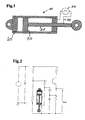
- FIG. 1 shows the piston-cylinder unit 10 according to the invention with a device for position determination.
- the construction of the piston-cylinder unit 10 is similar to a known piston-cylinder unit.
- the unit 10 comprises a tubular cylinder jacket 20, in the cavity of which a piston 30 with arranged piston rod 31 is mounted linearly displaceable.
- the piston-cylinder unit 10 is preferably used in construction machines or lifting devices, wherein a fixed implement is driven by the piston-cylinder unit 10.
- the automatic operation of the implement requires the precise positioning of the piston 30th
- the piston 30 forms a first electrode of a series resonant circuit and the cylinder jacket 20, the second electrode of the series resonant circuit.
- the piston 30, nor the piston rod 31 are conductively connected to the cylinder jacket 20, but instead via seals between the piston 30 and cylinder shell 20 and in the opening region of the cylinder jacket 20th and the exiting piston rod 31 slidably mounted.
- a hydraulic medium in particular hydraulic oil, which acts as a dielectric between the two electrodes.
- an oscillator 50 which is on the electrical lines 40 once with the cylinder jacket 20 and the piston rod 31 in conjunction.
- the oscillator After excitation of the resonant circuit via the oscillator 50, the oscillator oscillates at its resonant frequency.
- the formed impedance of piston 30 and cylinder shell 20 depends on the respective position of the piston 30 in the cavity of the cylinder. Since the capacitance or inductance of the resonant circuit influence the adjusting resonant frequency, a conclusion about the present impedance of the piston-cylinder unit 10 can be made on the basis of the detected resonant frequency.
- a corresponding output voltage V out is tapped off in the region of the oscillator 50 and analyzed or interpreted by a corresponding evaluation means, not shown, and optionally indicated optically or acoustically.
- the electrical contact between the oscillator 50 and the movable piston rod 31 is realized by means of a sliding contact.
- the piston rod 31 facing the end of the connecting line 40 of the oscillator 50 has for this purpose a brush contact, which extends slidably on the surface of the piston rod 31.
- the brushes of this contact point are preferably made of carbon, bronze or other suitable material.
- FIG. 2 shows a circuit diagram of the inventive piston-cylinder unit 10 with the corresponding interconnected device for determining position.
- the marked output voltage V out has an oscillating signal course and accordingly describes the present resonance frequency of the entire resonant circuit. This voltage or the voltage curve changes depending on the corresponding piston position of the piston-cylinder unit 10th
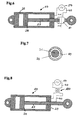
- FIG. 3 is that out FIG. 1 known piston-cylinder unit 10 according to the invention, this being supplemented by an additional inductance between the oscillator 50 and the cylinder jacket 20. Since the resonant circuit formed oscillates in a high-frequency resonant frequency range, the resonant frequency can be significantly reduced by the additionally series-connected inductor 60.
- an additional shield 70 installed, which covers the area around the oscillator 50, and shields the released electromagnetic waves due to the antenna characteristics of the piston-cylinder unit 10 to the environment.
- a shield 70 is made of a ferromagnetic material, for example. Of course, all materials are conceivable that ensure adequate shielding of the electromagnetic waves.
- the cylinder jacket 20 can be misused as a shielding means.
- the oscillator 50 is mounted in the cavity of the cylinder jacket 20.
- spark suppressors may be connected at the outputs of the oscillator 50.
- connection between oscillator 50 and piston rod 31 can be implemented by means of a capacitive or conductive ring 80. As in FIG. 6 shown, runs such a ring 80 coaxial with the piston rod 31 and slidably on the surface of the piston rod 31.
- FIG. 7 A sectional view along the section axis AA is the FIG. 7 refer to.
- This shows the capacitive ring 80, which is made of a conductive material. Between the piston rod 31 and the capacitive ring 80 is a dielectric 90. Ring 80 and piston rod 31 form a constant capacitance, which is connected in series with the resonant circuit.
- FIG. 8 shows a possible decoupling of the oscillator 50 from the piston-cylinder unit 10.
- the electrical connection is made via a transformer 100.
- the internal inductance of the transformer 100 acts as an additional series-connected inductance of the resonant circuit, whereby the self-adjusting resonant frequency is further reduced.
- electrical isolation between the cylinder and the oscillator 50 is realized by the transformer 100.
Landscapes
- Engineering & Computer Science (AREA)
- Physics & Mathematics (AREA)
- Fluid Mechanics (AREA)
- Mechanical Engineering (AREA)
- General Engineering & Computer Science (AREA)
- Electromagnetism (AREA)
- Health & Medical Sciences (AREA)
- Radar, Positioning & Navigation (AREA)
- Remote Sensing (AREA)
- Toxicology (AREA)
- Actuator (AREA)
- Measurement Of Length, Angles, Or The Like Using Electric Or Magnetic Means (AREA)
- Pistons, Piston Rings, And Cylinders (AREA)
Applications Claiming Priority (1)
| Application Number | Priority Date | Filing Date | Title |
|---|---|---|---|
| DE102011008381A DE102011008381A1 (de) | 2011-01-12 | 2011-01-12 | Kolben-Zylinder-Einheit mit Vorrichtung zur Positionsbestimmung |
Publications (3)
| Publication Number | Publication Date |
|---|---|
| EP2476916A2 true EP2476916A2 (fr) | 2012-07-18 |
| EP2476916A3 EP2476916A3 (fr) | 2014-03-26 |
| EP2476916B1 EP2476916B1 (fr) | 2017-08-16 |
Family
ID=45470172
Family Applications (1)
| Application Number | Title | Priority Date | Filing Date |
|---|---|---|---|
| EP11010014.6A Not-in-force EP2476916B1 (fr) | 2011-01-12 | 2011-12-20 | Vérin avec dispositif de détermination de position |
Country Status (4)
| Country | Link |
|---|---|
| US (1) | US9027460B2 (fr) |
| EP (1) | EP2476916B1 (fr) |
| JP (1) | JP2012145226A (fr) |
| DE (1) | DE102011008381A1 (fr) |
Cited By (1)
| Publication number | Priority date | Publication date | Assignee | Title |
|---|---|---|---|---|
| EP2876308A1 (fr) * | 2013-10-31 | 2015-05-27 | Liebherr-Elektronik GmbH | Unité de vérin à piston possédant une unité d'évaluation destinée à la détermination de la position du piston |
Families Citing this family (7)
| Publication number | Priority date | Publication date | Assignee | Title |
|---|---|---|---|---|
| GB0911016D0 (en) | 2009-06-25 | 2009-08-12 | Airbus Operations Ltd | Electrical power transmitting telescopic strut |
| DE102012100335B4 (de) * | 2012-01-16 | 2013-11-07 | Parker Hannifin Manufacturing Germany GmbH & Co. KG | Druckbehälter mit einem darin beweglichen Kolben und einer Vorrichtung zur Positionsbestimmung des Kolbens in dem Druckbehälter |
| NO20120980A1 (no) * | 2012-08-31 | 2014-03-03 | Aker Mh As | Antennesammenstilling for stempelakkumulatorer |
| DE102013001121A1 (de) | 2013-01-23 | 2014-07-24 | Liebherr-Elektronik Gmbh | Verfahren zur Bestimmung der Kolbenposition einer Kolbenzylindereinheit und Kolbenzylindereinheit |
| US10365370B2 (en) | 2016-10-31 | 2019-07-30 | Timothy Webster | Wear tolerant hydraulic / pneumatic piston position sensing using optical sensors |
| EP4169822A4 (fr) * | 2020-06-23 | 2024-03-27 | Hitachi Astemo, Ltd. | Dispositif d'étalonnage, système de suspension, véhicule du type à selle et procédé d'étalonnage |
| WO2023033779A1 (fr) * | 2021-09-02 | 2023-03-09 | Skvorchevsky Alexander | Entraînement asservi électro-hydraulique et procédé de commande de la position de sa tige avec un piston |
Family Cites Families (7)
| Publication number | Priority date | Publication date | Assignee | Title |
|---|---|---|---|---|
| FR1525363A (fr) * | 1967-04-07 | 1968-05-17 | Compteurs Et Moteurs Aster | Vérin comportant un dispositif de contrôle et de commande de sa position |
| US4901628A (en) * | 1983-08-11 | 1990-02-20 | General Motors Corporation | Hydraulic actuator having a microwave antenna |
| US5901633A (en) * | 1996-11-27 | 1999-05-11 | Case Corporation | Method and apparatus for sensing piston position using a dipstick assembly |
| DE20218623U1 (de) * | 2002-11-30 | 2003-02-13 | FESTO AG & Co., 73734 Esslingen | Positionsmessvorrichtung für fluidische Zylinder |
| WO2007011402A2 (fr) * | 2004-10-26 | 2007-01-25 | Georgia Tech Research Corporation | Capteur de deplacement |
| EP1752665B1 (fr) * | 2005-08-11 | 2009-05-06 | Festo AG & Co. KG | Dispositif d'actionnement avec un capteur de position à micro-ondes. |
| DE202008010230U1 (de) * | 2008-07-31 | 2009-12-10 | Liebherr-Elektronik Gmbh | Positionsmeßvorrichtung für einen fluidischen Zylinder |
-
2011
- 2011-01-12 DE DE102011008381A patent/DE102011008381A1/de not_active Withdrawn
- 2011-12-20 EP EP11010014.6A patent/EP2476916B1/fr not_active Not-in-force
-
2012
- 2012-01-11 US US13/347,935 patent/US9027460B2/en active Active
- 2012-01-11 JP JP2012003227A patent/JP2012145226A/ja active Pending
Non-Patent Citations (1)
| Title |
|---|
| None |
Cited By (2)
| Publication number | Priority date | Publication date | Assignee | Title |
|---|---|---|---|---|
| EP2876308A1 (fr) * | 2013-10-31 | 2015-05-27 | Liebherr-Elektronik GmbH | Unité de vérin à piston possédant une unité d'évaluation destinée à la détermination de la position du piston |
| US9778015B2 (en) | 2013-10-31 | 2017-10-03 | Liebherr-Elektronik Gmbh | Piston-cylinder unit with evaluation unit for determining the piston position |
Also Published As
| Publication number | Publication date |
|---|---|
| US9027460B2 (en) | 2015-05-12 |
| US20120174771A1 (en) | 2012-07-12 |
| EP2476916B1 (fr) | 2017-08-16 |
| DE102011008381A1 (de) | 2012-07-12 |
| EP2476916A3 (fr) | 2014-03-26 |
| JP2012145226A (ja) | 2012-08-02 |
Similar Documents
| Publication | Publication Date | Title |
|---|---|---|
| EP2476916B1 (fr) | Vérin avec dispositif de détermination de position | |
| DE3910297C2 (fr) | ||
| EP2149715B1 (fr) | Dispositif de détection de position pour un vérin fluidique | |
| DE102015114205B4 (de) | Wegmessverfahren für einen magnetischen Sensor und Sensor | |
| EP2304866B1 (fr) | Procédé et système pour contrôler le courant de palier d'une machine électrique | |
| DE102013005963A1 (de) | Kapazitiver Füllstandssensor | |
| EP0922853A1 (fr) | Dispositif de mesure de la course d'une soupape | |
| DE102011102796A1 (de) | Positionssensor, Aktor-Sensor-Vorrichtung und Verfahren zur induktiven Erfassung einer Position | |
| EP2876308B1 (fr) | Unité de vérin à piston possédant une unité d'évaluation destinée à la détermination de la position du piston | |
| DE202014001604U1 (de) | Kolbenzylindereinheit | |
| DE102016107970A1 (de) | Koppelelement für ein kapazitives Füllstandsmessgerät | |
| DE102013018808A1 (de) | Abstandsmessvorrichtung zur Ermittlung eines Abstandes sowie Verfahren zur Ermittlung des Abstands | |
| DE102008027921B4 (de) | Admittanzmeßvorrichtung für einen Füllstandsensor | |
| WO2020065366A1 (fr) | Dispositif de détection d'un contact avec un conducteur électrique, procédé de détection d'un contact avec un conducteur électrique, et machine à dénuder munie dudit dispositif | |
| EP2759715B1 (fr) | Procédé de détermination de la position du piston d'un vérin et ensemble comportant un tel vérin | |
| DE102013215320A1 (de) | Vorrichtung zur Erfassung des Drehmomentes in einer Welle | |
| DE202010011758U1 (de) | Sensoranordnung zur kontaktlosen Ermittlung der aktuellen Winkelstellung einer Welle | |
| EP4073476B1 (fr) | Unité de pipetage à détection de liquide capacitive, combinaison d'une unité de pipetage de ce type et d'une pointe de pipetage, et procédé de détection capacitive de liquide de pipetage | |
| DE102008012053A1 (de) | Induktiv arbeitender Sensor | |
| EP2492640B1 (fr) | Dispositif inductif de mesure de déplacement | |
| EP2492642B1 (fr) | Capteur inductif de déplacement | |
| EP3150864A1 (fr) | Dispositif et procede de determination de position d'un piston de verin | |
| DE102020132081A1 (de) | Sensoreinheit zur Ausbildung eines Sensorknotens in einem drahtlosen Sensornetzwerk und drahtloses Sensornetzwerk umfassend einen solchen Sensorknoten | |
| EP2607932B1 (fr) | Procédé de mesure capacitif avec directivité commandable et capteur capacitif adapté pour l'usage industriel | |
| DE102019103670B4 (de) | Induktiver Sensor und Verfahren zu seinem Betrieb |
Legal Events
| Date | Code | Title | Description |
|---|---|---|---|
| PUAI | Public reference made under article 153(3) epc to a published international application that has entered the european phase |
Free format text: ORIGINAL CODE: 0009012 |
|
| AK | Designated contracting states |
Kind code of ref document: A2 Designated state(s): AL AT BE BG CH CY CZ DE DK EE ES FI FR GB GR HR HU IE IS IT LI LT LU LV MC MK MT NL NO PL PT RO RS SE SI SK SM TR |
|
| AX | Request for extension of the european patent |
Extension state: BA ME |
|
| PUAL | Search report despatched |
Free format text: ORIGINAL CODE: 0009013 |
|
| AK | Designated contracting states |
Kind code of ref document: A3 Designated state(s): AL AT BE BG CH CY CZ DE DK EE ES FI FR GB GR HR HU IE IS IT LI LT LU LV MC MK MT NL NO PL PT RO RS SE SI SK SM TR |
|
| AX | Request for extension of the european patent |
Extension state: BA ME |
|
| RIC1 | Information provided on ipc code assigned before grant |
Ipc: F15B 15/28 20060101AFI20140218BHEP |
|
| 17P | Request for examination filed |
Effective date: 20140915 |
|
| GRAP | Despatch of communication of intention to grant a patent |
Free format text: ORIGINAL CODE: EPIDOSNIGR1 |
|
| INTG | Intention to grant announced |
Effective date: 20170407 |
|
| GRAS | Grant fee paid |
Free format text: ORIGINAL CODE: EPIDOSNIGR3 |
|
| GRAA | (expected) grant |
Free format text: ORIGINAL CODE: 0009210 |
|
| AK | Designated contracting states |
Kind code of ref document: B1 Designated state(s): AL AT BE BG CH CY CZ DE DK EE ES FI FR GB GR HR HU IE IS IT LI LT LU LV MC MK MT NL NO PL PT RO RS SE SI SK SM TR |
|
| REG | Reference to a national code |
Ref country code: GB Ref legal event code: FG4D Free format text: NOT ENGLISH |
|
| REG | Reference to a national code |
Ref country code: CH Ref legal event code: EP |
|
| REG | Reference to a national code |
Ref country code: IE Ref legal event code: FG4D Free format text: LANGUAGE OF EP DOCUMENT: GERMAN |
|
| REG | Reference to a national code |
Ref country code: AT Ref legal event code: REF Ref document number: 919352 Country of ref document: AT Kind code of ref document: T Effective date: 20170915 |
|
| REG | Reference to a national code |
Ref country code: DE Ref legal event code: R096 Ref document number: 502011012784 Country of ref document: DE |
|
| REG | Reference to a national code |
Ref country code: SE Ref legal event code: TRGR |
|
| REG | Reference to a national code |
Ref country code: NL Ref legal event code: MP Effective date: 20170816 |
|
| REG | Reference to a national code |
Ref country code: FR Ref legal event code: PLFP Year of fee payment: 7 |
|
| REG | Reference to a national code |
Ref country code: LT Ref legal event code: MG4D |
|
| PG25 | Lapsed in a contracting state [announced via postgrant information from national office to epo] |
Ref country code: NO Free format text: LAPSE BECAUSE OF FAILURE TO SUBMIT A TRANSLATION OF THE DESCRIPTION OR TO PAY THE FEE WITHIN THE PRESCRIBED TIME-LIMIT Effective date: 20171116 Ref country code: LT Free format text: LAPSE BECAUSE OF FAILURE TO SUBMIT A TRANSLATION OF THE DESCRIPTION OR TO PAY THE FEE WITHIN THE PRESCRIBED TIME-LIMIT Effective date: 20170816 Ref country code: NL Free format text: LAPSE BECAUSE OF FAILURE TO SUBMIT A TRANSLATION OF THE DESCRIPTION OR TO PAY THE FEE WITHIN THE PRESCRIBED TIME-LIMIT Effective date: 20170816 |
|
| PG25 | Lapsed in a contracting state [announced via postgrant information from national office to epo] |
Ref country code: IS Free format text: LAPSE BECAUSE OF FAILURE TO SUBMIT A TRANSLATION OF THE DESCRIPTION OR TO PAY THE FEE WITHIN THE PRESCRIBED TIME-LIMIT Effective date: 20171216 Ref country code: PL Free format text: LAPSE BECAUSE OF FAILURE TO SUBMIT A TRANSLATION OF THE DESCRIPTION OR TO PAY THE FEE WITHIN THE PRESCRIBED TIME-LIMIT Effective date: 20170816 Ref country code: BG Free format text: LAPSE BECAUSE OF FAILURE TO SUBMIT A TRANSLATION OF THE DESCRIPTION OR TO PAY THE FEE WITHIN THE PRESCRIBED TIME-LIMIT Effective date: 20171116 Ref country code: GR Free format text: LAPSE BECAUSE OF FAILURE TO SUBMIT A TRANSLATION OF THE DESCRIPTION OR TO PAY THE FEE WITHIN THE PRESCRIBED TIME-LIMIT Effective date: 20171117 Ref country code: ES Free format text: LAPSE BECAUSE OF FAILURE TO SUBMIT A TRANSLATION OF THE DESCRIPTION OR TO PAY THE FEE WITHIN THE PRESCRIBED TIME-LIMIT Effective date: 20170816 Ref country code: LV Free format text: LAPSE BECAUSE OF FAILURE TO SUBMIT A TRANSLATION OF THE DESCRIPTION OR TO PAY THE FEE WITHIN THE PRESCRIBED TIME-LIMIT Effective date: 20170816 Ref country code: RS Free format text: LAPSE BECAUSE OF FAILURE TO SUBMIT A TRANSLATION OF THE DESCRIPTION OR TO PAY THE FEE WITHIN THE PRESCRIBED TIME-LIMIT Effective date: 20170816 |
|
| PG25 | Lapsed in a contracting state [announced via postgrant information from national office to epo] |
Ref country code: CZ Free format text: LAPSE BECAUSE OF FAILURE TO SUBMIT A TRANSLATION OF THE DESCRIPTION OR TO PAY THE FEE WITHIN THE PRESCRIBED TIME-LIMIT Effective date: 20170816 Ref country code: DK Free format text: LAPSE BECAUSE OF FAILURE TO SUBMIT A TRANSLATION OF THE DESCRIPTION OR TO PAY THE FEE WITHIN THE PRESCRIBED TIME-LIMIT Effective date: 20170816 Ref country code: RO Free format text: LAPSE BECAUSE OF FAILURE TO SUBMIT A TRANSLATION OF THE DESCRIPTION OR TO PAY THE FEE WITHIN THE PRESCRIBED TIME-LIMIT Effective date: 20170816 |
|
| REG | Reference to a national code |
Ref country code: DE Ref legal event code: R097 Ref document number: 502011012784 Country of ref document: DE |
|
| PG25 | Lapsed in a contracting state [announced via postgrant information from national office to epo] |
Ref country code: SK Free format text: LAPSE BECAUSE OF FAILURE TO SUBMIT A TRANSLATION OF THE DESCRIPTION OR TO PAY THE FEE WITHIN THE PRESCRIBED TIME-LIMIT Effective date: 20170816 Ref country code: EE Free format text: LAPSE BECAUSE OF FAILURE TO SUBMIT A TRANSLATION OF THE DESCRIPTION OR TO PAY THE FEE WITHIN THE PRESCRIBED TIME-LIMIT Effective date: 20170816 Ref country code: SM Free format text: LAPSE BECAUSE OF FAILURE TO SUBMIT A TRANSLATION OF THE DESCRIPTION OR TO PAY THE FEE WITHIN THE PRESCRIBED TIME-LIMIT Effective date: 20170816 |
|
| PLBE | No opposition filed within time limit |
Free format text: ORIGINAL CODE: 0009261 |
|
| STAA | Information on the status of an ep patent application or granted ep patent |
Free format text: STATUS: NO OPPOSITION FILED WITHIN TIME LIMIT |
|
| 26N | No opposition filed |
Effective date: 20180517 |
|
| REG | Reference to a national code |
Ref country code: CH Ref legal event code: PL |
|
| GBPC | Gb: european patent ceased through non-payment of renewal fee |
Effective date: 20171220 |
|
| PG25 | Lapsed in a contracting state [announced via postgrant information from national office to epo] |
Ref country code: SI Free format text: LAPSE BECAUSE OF FAILURE TO SUBMIT A TRANSLATION OF THE DESCRIPTION OR TO PAY THE FEE WITHIN THE PRESCRIBED TIME-LIMIT Effective date: 20170816 |
|
| REG | Reference to a national code |
Ref country code: IE Ref legal event code: MM4A |
|
| PG25 | Lapsed in a contracting state [announced via postgrant information from national office to epo] |
Ref country code: MT Free format text: LAPSE BECAUSE OF FAILURE TO SUBMIT A TRANSLATION OF THE DESCRIPTION OR TO PAY THE FEE WITHIN THE PRESCRIBED TIME-LIMIT Effective date: 20170816 Ref country code: LU Free format text: LAPSE BECAUSE OF NON-PAYMENT OF DUE FEES Effective date: 20171220 |
|
| REG | Reference to a national code |
Ref country code: BE Ref legal event code: MM Effective date: 20171231 |
|
| PG25 | Lapsed in a contracting state [announced via postgrant information from national office to epo] |
Ref country code: IE Free format text: LAPSE BECAUSE OF NON-PAYMENT OF DUE FEES Effective date: 20171220 |
|
| PG25 | Lapsed in a contracting state [announced via postgrant information from national office to epo] |
Ref country code: CH Free format text: LAPSE BECAUSE OF NON-PAYMENT OF DUE FEES Effective date: 20171231 Ref country code: LI Free format text: LAPSE BECAUSE OF NON-PAYMENT OF DUE FEES Effective date: 20171231 Ref country code: BE Free format text: LAPSE BECAUSE OF NON-PAYMENT OF DUE FEES Effective date: 20171231 Ref country code: GB Free format text: LAPSE BECAUSE OF NON-PAYMENT OF DUE FEES Effective date: 20171220 |
|
| PG25 | Lapsed in a contracting state [announced via postgrant information from national office to epo] |
Ref country code: MC Free format text: LAPSE BECAUSE OF FAILURE TO SUBMIT A TRANSLATION OF THE DESCRIPTION OR TO PAY THE FEE WITHIN THE PRESCRIBED TIME-LIMIT Effective date: 20170816 Ref country code: HU Free format text: LAPSE BECAUSE OF FAILURE TO SUBMIT A TRANSLATION OF THE DESCRIPTION OR TO PAY THE FEE WITHIN THE PRESCRIBED TIME-LIMIT; INVALID AB INITIO Effective date: 20111220 |
|
| PG25 | Lapsed in a contracting state [announced via postgrant information from national office to epo] |
Ref country code: CY Free format text: LAPSE BECAUSE OF NON-PAYMENT OF DUE FEES Effective date: 20170816 |
|
| PG25 | Lapsed in a contracting state [announced via postgrant information from national office to epo] |
Ref country code: MK Free format text: LAPSE BECAUSE OF FAILURE TO SUBMIT A TRANSLATION OF THE DESCRIPTION OR TO PAY THE FEE WITHIN THE PRESCRIBED TIME-LIMIT Effective date: 20170816 |
|
| PG25 | Lapsed in a contracting state [announced via postgrant information from national office to epo] |
Ref country code: TR Free format text: LAPSE BECAUSE OF FAILURE TO SUBMIT A TRANSLATION OF THE DESCRIPTION OR TO PAY THE FEE WITHIN THE PRESCRIBED TIME-LIMIT Effective date: 20170816 |
|
| PG25 | Lapsed in a contracting state [announced via postgrant information from national office to epo] |
Ref country code: PT Free format text: LAPSE BECAUSE OF FAILURE TO SUBMIT A TRANSLATION OF THE DESCRIPTION OR TO PAY THE FEE WITHIN THE PRESCRIBED TIME-LIMIT Effective date: 20170816 |
|
| PG25 | Lapsed in a contracting state [announced via postgrant information from national office to epo] |
Ref country code: HR Free format text: LAPSE BECAUSE OF FAILURE TO SUBMIT A TRANSLATION OF THE DESCRIPTION OR TO PAY THE FEE WITHIN THE PRESCRIBED TIME-LIMIT Effective date: 20170816 |
|
| PG25 | Lapsed in a contracting state [announced via postgrant information from national office to epo] |
Ref country code: AL Free format text: LAPSE BECAUSE OF FAILURE TO SUBMIT A TRANSLATION OF THE DESCRIPTION OR TO PAY THE FEE WITHIN THE PRESCRIBED TIME-LIMIT Effective date: 20170816 |
|
| PGFP | Annual fee paid to national office [announced via postgrant information from national office to epo] |
Ref country code: SE Payment date: 20231220 Year of fee payment: 13 Ref country code: IT Payment date: 20231227 Year of fee payment: 13 Ref country code: FR Payment date: 20231220 Year of fee payment: 13 Ref country code: FI Payment date: 20231227 Year of fee payment: 13 Ref country code: AT Payment date: 20231219 Year of fee payment: 13 |
|
| PGFP | Annual fee paid to national office [announced via postgrant information from national office to epo] |
Ref country code: DE Payment date: 20231221 Year of fee payment: 13 |
|
| REG | Reference to a national code |
Ref country code: DE Ref legal event code: R119 Ref document number: 502011012784 Country of ref document: DE |
|
| PG25 | Lapsed in a contracting state [announced via postgrant information from national office to epo] |
Ref country code: FI Free format text: LAPSE BECAUSE OF NON-PAYMENT OF DUE FEES Effective date: 20241220 |
|
| REG | Reference to a national code |
Ref country code: SE Ref legal event code: EUG |
|
| REG | Reference to a national code |
Ref country code: AT Ref legal event code: MM01 Ref document number: 919352 Country of ref document: AT Kind code of ref document: T Effective date: 20241220 |
|
| PG25 | Lapsed in a contracting state [announced via postgrant information from national office to epo] |
Ref country code: DE Free format text: LAPSE BECAUSE OF NON-PAYMENT OF DUE FEES Effective date: 20250701 |
|
| PG25 | Lapsed in a contracting state [announced via postgrant information from national office to epo] |
Ref country code: IT Free format text: LAPSE BECAUSE OF NON-PAYMENT OF DUE FEES Effective date: 20241220 |
|
| PG25 | Lapsed in a contracting state [announced via postgrant information from national office to epo] |
Ref country code: AT Free format text: LAPSE BECAUSE OF NON-PAYMENT OF DUE FEES Effective date: 20241220 Ref country code: FR Free format text: LAPSE BECAUSE OF NON-PAYMENT OF DUE FEES Effective date: 20241231 |