EP2476925A1 - Cage de roulement constitué partiellement en matériau composite renforcé par des filaments - Google Patents
Cage de roulement constitué partiellement en matériau composite renforcé par des filaments Download PDFInfo
- Publication number
- EP2476925A1 EP2476925A1 EP20110150759 EP11150759A EP2476925A1 EP 2476925 A1 EP2476925 A1 EP 2476925A1 EP 20110150759 EP20110150759 EP 20110150759 EP 11150759 A EP11150759 A EP 11150759A EP 2476925 A1 EP2476925 A1 EP 2476925A1
- Authority
- EP
- European Patent Office
- Prior art keywords
- plastic
- fiber composite
- fibers
- rolling element
- section
- Prior art date
- Legal status (The legal status is an assumption and is not a legal conclusion. Google has not performed a legal analysis and makes no representation as to the accuracy of the status listed.)
- Withdrawn
Links
- 238000005096 rolling process Methods 0.000 title claims abstract description 82
- 239000002131 composite material Substances 0.000 title claims abstract description 65
- 239000000835 fiber Substances 0.000 claims abstract description 105
- 239000004033 plastic Substances 0.000 claims abstract description 89
- 229920003023 plastic Polymers 0.000 claims abstract description 89
- 239000000463 material Substances 0.000 claims abstract description 12
- 229920000049 Carbon (fiber) Polymers 0.000 claims abstract description 9
- 239000004917 carbon fiber Substances 0.000 claims abstract description 9
- 239000002557 mineral fiber Substances 0.000 claims abstract description 5
- 238000004519 manufacturing process Methods 0.000 claims abstract description 4
- 229920002430 Fibre-reinforced plastic Polymers 0.000 claims abstract description 3
- 239000011151 fibre-reinforced plastic Substances 0.000 claims abstract description 3
- 239000011159 matrix material Substances 0.000 claims description 11
- 238000000034 method Methods 0.000 abstract description 4
- 229920002994 synthetic fiber Polymers 0.000 abstract description 3
- 239000012209 synthetic fiber Substances 0.000 abstract description 3
- 230000009021 linear effect Effects 0.000 description 10
- 239000000203 mixture Substances 0.000 description 7
- 239000003365 glass fiber Substances 0.000 description 6
- 239000002245 particle Substances 0.000 description 4
- OKTJSMMVPCPJKN-UHFFFAOYSA-N Carbon Chemical compound [C] OKTJSMMVPCPJKN-UHFFFAOYSA-N 0.000 description 3
- 229910000831 Steel Inorganic materials 0.000 description 3
- 238000010276 construction Methods 0.000 description 3
- 239000003822 epoxy resin Substances 0.000 description 3
- 239000000314 lubricant Substances 0.000 description 3
- 229920000647 polyepoxide Polymers 0.000 description 3
- 239000010959 steel Substances 0.000 description 3
- 239000000654 additive Substances 0.000 description 2
- 230000000996 additive effect Effects 0.000 description 2
- 238000010924 continuous production Methods 0.000 description 2
- 239000010439 graphite Substances 0.000 description 2
- 229910002804 graphite Inorganic materials 0.000 description 2
- 238000009940 knitting Methods 0.000 description 2
- 239000007787 solid Substances 0.000 description 2
- 238000003860 storage Methods 0.000 description 2
- 240000008564 Boehmeria nivea Species 0.000 description 1
- 239000004952 Polyamide Substances 0.000 description 1
- 238000010521 absorption reaction Methods 0.000 description 1
- 230000006978 adaptation Effects 0.000 description 1
- 238000004026 adhesive bonding Methods 0.000 description 1
- 239000004760 aramid Substances 0.000 description 1
- 229920006231 aramid fiber Polymers 0.000 description 1
- 230000015572 biosynthetic process Effects 0.000 description 1
- 239000002041 carbon nanotube Substances 0.000 description 1
- 229910021393 carbon nanotube Inorganic materials 0.000 description 1
- 238000001816 cooling Methods 0.000 description 1
- 230000002349 favourable effect Effects 0.000 description 1
- 239000002657 fibrous material Substances 0.000 description 1
- 229920002313 fluoropolymer Polymers 0.000 description 1
- 239000004811 fluoropolymer Substances 0.000 description 1
- 238000002347 injection Methods 0.000 description 1
- 239000007924 injection Substances 0.000 description 1
- 238000001746 injection moulding Methods 0.000 description 1
- 239000007788 liquid Substances 0.000 description 1
- 230000001050 lubricating effect Effects 0.000 description 1
- 239000002184 metal Substances 0.000 description 1
- 239000004745 nonwoven fabric Substances 0.000 description 1
- -1 platelets Substances 0.000 description 1
- 229920002647 polyamide Polymers 0.000 description 1
- 238000009417 prefabrication Methods 0.000 description 1
- 230000002787 reinforcement Effects 0.000 description 1
- 229920005989 resin Polymers 0.000 description 1
- 239000011347 resin Substances 0.000 description 1
- 238000005507 spraying Methods 0.000 description 1
- 230000008961 swelling Effects 0.000 description 1
- 239000000454 talc Substances 0.000 description 1
- 229910052623 talc Inorganic materials 0.000 description 1
- 229920001169 thermoplastic Polymers 0.000 description 1
- 239000004416 thermosoftening plastic Substances 0.000 description 1
- 238000001721 transfer moulding Methods 0.000 description 1
- 238000003466 welding Methods 0.000 description 1
- 239000002759 woven fabric Substances 0.000 description 1
Images

Classifications
-
- F—MECHANICAL ENGINEERING; LIGHTING; HEATING; WEAPONS; BLASTING
- F16—ENGINEERING ELEMENTS AND UNITS; GENERAL MEASURES FOR PRODUCING AND MAINTAINING EFFECTIVE FUNCTIONING OF MACHINES OR INSTALLATIONS; THERMAL INSULATION IN GENERAL
- F16C—SHAFTS; FLEXIBLE SHAFTS; ELEMENTS OR CRANKSHAFT MECHANISMS; ROTARY BODIES OTHER THAN GEARING ELEMENTS; BEARINGS
- F16C33/00—Parts of bearings; Special methods for making bearings or parts thereof
- F16C33/30—Parts of ball or roller bearings
- F16C33/38—Ball cages
- F16C33/3825—Ball cages formed as a flexible belt, e.g. spacers connected by a thin film
-
- F—MECHANICAL ENGINEERING; LIGHTING; HEATING; WEAPONS; BLASTING
- F16—ENGINEERING ELEMENTS AND UNITS; GENERAL MEASURES FOR PRODUCING AND MAINTAINING EFFECTIVE FUNCTIONING OF MACHINES OR INSTALLATIONS; THERMAL INSULATION IN GENERAL
- F16C—SHAFTS; FLEXIBLE SHAFTS; ELEMENTS OR CRANKSHAFT MECHANISMS; ROTARY BODIES OTHER THAN GEARING ELEMENTS; BEARINGS
- F16C33/00—Parts of bearings; Special methods for making bearings or parts thereof
- F16C33/30—Parts of ball or roller bearings
- F16C33/38—Ball cages
- F16C33/3831—Ball cages with hybrid structure, i.e. with parts made of distinct materials
-
- F—MECHANICAL ENGINEERING; LIGHTING; HEATING; WEAPONS; BLASTING
- F16—ENGINEERING ELEMENTS AND UNITS; GENERAL MEASURES FOR PRODUCING AND MAINTAINING EFFECTIVE FUNCTIONING OF MACHINES OR INSTALLATIONS; THERMAL INSULATION IN GENERAL
- F16C—SHAFTS; FLEXIBLE SHAFTS; ELEMENTS OR CRANKSHAFT MECHANISMS; ROTARY BODIES OTHER THAN GEARING ELEMENTS; BEARINGS
- F16C33/00—Parts of bearings; Special methods for making bearings or parts thereof
- F16C33/30—Parts of ball or roller bearings
- F16C33/38—Ball cages
- F16C33/44—Selection of substances
-
- F—MECHANICAL ENGINEERING; LIGHTING; HEATING; WEAPONS; BLASTING
- F16—ENGINEERING ELEMENTS AND UNITS; GENERAL MEASURES FOR PRODUCING AND MAINTAINING EFFECTIVE FUNCTIONING OF MACHINES OR INSTALLATIONS; THERMAL INSULATION IN GENERAL
- F16C—SHAFTS; FLEXIBLE SHAFTS; ELEMENTS OR CRANKSHAFT MECHANISMS; ROTARY BODIES OTHER THAN GEARING ELEMENTS; BEARINGS
- F16C2208/00—Plastics; Synthetic resins, e.g. rubbers
- F16C2208/80—Thermosetting resins
- F16C2208/82—Composites, i.e. fibre reinforced thermosetting resins
-
- F—MECHANICAL ENGINEERING; LIGHTING; HEATING; WEAPONS; BLASTING
- F16—ENGINEERING ELEMENTS AND UNITS; GENERAL MEASURES FOR PRODUCING AND MAINTAINING EFFECTIVE FUNCTIONING OF MACHINES OR INSTALLATIONS; THERMAL INSULATION IN GENERAL
- F16C—SHAFTS; FLEXIBLE SHAFTS; ELEMENTS OR CRANKSHAFT MECHANISMS; ROTARY BODIES OTHER THAN GEARING ELEMENTS; BEARINGS
- F16C2220/00—Shaping
- F16C2220/02—Shaping by casting
- F16C2220/04—Shaping by casting by injection-moulding
-
- F—MECHANICAL ENGINEERING; LIGHTING; HEATING; WEAPONS; BLASTING
- F16—ENGINEERING ELEMENTS AND UNITS; GENERAL MEASURES FOR PRODUCING AND MAINTAINING EFFECTIVE FUNCTIONING OF MACHINES OR INSTALLATIONS; THERMAL INSULATION IN GENERAL
- F16C—SHAFTS; FLEXIBLE SHAFTS; ELEMENTS OR CRANKSHAFT MECHANISMS; ROTARY BODIES OTHER THAN GEARING ELEMENTS; BEARINGS
- F16C2300/00—Application independent of particular apparatuses
- F16C2300/10—Application independent of particular apparatuses related to size
- F16C2300/14—Large applications, e.g. bearings having an inner diameter exceeding 500 mm
-
- F—MECHANICAL ENGINEERING; LIGHTING; HEATING; WEAPONS; BLASTING
- F16—ENGINEERING ELEMENTS AND UNITS; GENERAL MEASURES FOR PRODUCING AND MAINTAINING EFFECTIVE FUNCTIONING OF MACHINES OR INSTALLATIONS; THERMAL INSULATION IN GENERAL
- F16C—SHAFTS; FLEXIBLE SHAFTS; ELEMENTS OR CRANKSHAFT MECHANISMS; ROTARY BODIES OTHER THAN GEARING ELEMENTS; BEARINGS
- F16C2340/00—Apparatus for treating textiles
Definitions
- the invention relates to a WälzMechhimfig for rolling bearings.
- Rolling bearings basically include a number of rolling elements, which are held in at least in some applications in a rolling bearing cage. This has the task to distance the rolling elements and to prevent their mutual contact.
- the cage made of metal or plastic material.
- the DE 103 51 346 to construct the rolling bearing cage of a matrix, for example of epoxy resin, in which a reinforcement in the form of a woven or nonwoven fabric made of polyamide fibers is embedded.
- the fibers serve to provide emergency running properties, which is based on their choice of material.
- the fibers can absorb, for example, lubricant.
- the DE 10 2004 058 518 A1 also proposes a roller bearing cage made of a composite material.
- the plastic is provided with an additive to reduce the coefficient of friction.
- a solid lubricant such as a fluoropolymer is proposed.
- the DE 10 2008 027 764 A1 proposes rolling bearing cages made of epoxy resin and ramie fibers for the construction of particularly high-speed bearings. These are linen-like bast fibers that help lessen the friction and to absorb oil.
- beats JP 2006-300257 A a rolling bearing with a cage, which consists of a composite material.
- This composite material is formed by a resin matrix with embedded carbon nanotubes. These have a very good thermal conductivity, which is used for the storage cooling.
- the method of claim 15 allows the production of a rolling bearing cage that meets the requirements set.
- the rolling element cage according to the invention has at least one, preferably a plurality of fiber composite sections, which consist of a fiber-reinforced plastic material. Furthermore, there are at least one plastic section, preferably a plurality of plastic sections, which are connected to the fiber composite section.
- the fiber composite portion may be elongated and arranged to extend in the longitudinal direction of the rolling element cage.
- the longitudinal direction is defined by the series of successively arranged rolling elements.
- the plastic portion may be formed so that it is firmly connected to the fiber composite portion or at least partially envelops or surrounds.
- the plastic sections may form webs which engage between the rolling elements. Between the plastic sections recesses may be formed, in which sit the rolling elements. It is possible to limit these recesses or pockets in the longitudinal direction by the plastic sections while they are limited in the lateral direction of the fiber composite sections.
- the Hauptreiblast exists between the plastic sections and the Rolling elements.
- the rolling elements and the plastic sections can touch.
- the plastic sections can be optimally matched to this task with regard to the choice of material.
- a fiber-free plastic can be used.
- plastics that form a favorable friction pairing with the rolling elements may be chosen.
- the plastic body may be filled with friction-reducing particles. These particles may be in the form of grains, tinsel or even fibers. It can be natural fibers or synthetic fibers.
- the plastic of the plastic sections may have emergency lubricating properties and may be filled with liquid and / or solid lubricants, for example graphite, talc or the like.
- the fiber composite section can be optimized in terms of other properties than the plastic section.
- the fiber composite portion may be optimized in terms of thermal linear expansion coefficient or expansion due to exposure to moisture.
- fibers for the fiber composite section mineral fibers, glass fibers, carbon fibers or the like can be used. With carbon fibers, a particularly low thermal expansion coefficient can be achieved. Because of the existing distance between the rolling elements and the fiber composite sections abrasive wear of the rolling elements can be minimized or prevented.
- the fibers are oriented in the longitudinal direction of the Wälz stressesmaschinefigs.
- the fibers are preferably embedded in a plastic matrix. It can find fiber mixtures application, whereby also fibers with the plastic the plastic matrix welded or glued, can be provided. It is also possible to provide fibers of a plastic which coincides with the plastic of the matrix, so that an optimal wrapping and wrapping of the other fibers of the fiber mixture takes place.
- endless fibers are used as fibers, these are fibers whose length is greater than the circumference of the bearing or its length. If it is a linear bearing. Preferably, the length of such a "continuous fiber" exceeds a multiple of the bearing circumference or the bearing length.
- the WälzMechchankafig can be designed as a linear cage for linear bearings, as a linear cage, which is formed into a ring in use or as a closed ring.
- the fiber composite section is produced in continuous production as a linear element, which is then provided in sections or in continuous production with the plastic sections.
- the cross-section of the fiber composite section may be round, square, rectangular or otherwise shaped. In particular, it is possible to form the fiber composite section in the form of a band.
- the plastic sections are preferably shaped so that they play around the rolling elements between each other, i. form matching pockets.
- the plastic portions are formed so that the rolling elements are held captive locked in the Wälz Eisenfig.
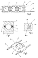
- FIG. 1 a linear roller bearing 10 is illustrated which has two raceways 11, 12. Between these rolling elements 13, 14, 15, 16 are arranged to support a raceway 12 rolling on the other raceway 11.
- the rolling elements 13-16 are balls in the present embodiment.
- the rolling elements 13 - 16 may also have other suitable shapes, such as cylindrical shape, barrel shape, truncated cone shape, needle shape or any other shape suitable for rolling elements.
- the rolling elements 13 - 16 (and other rolling elements, not shown) are held in a rolling element cage 17.
- This comprises at least one, preferably two fiber composite sections 18, 19 extending along the row formed by the rolling elements 13, 14, 15 and so on.
- FIG. 3 illustrates this.
- the two fiber composite sections 18, 19 may have a rectangular cross section, as it FIGS. 4 to 6 demonstrate. But you can also other cross-sectional shapes, such as round, oval, rectangular, triangular, polygonal o.ä. exhibit.
- the two elongated fiber composite sections 18, 19 preferably extend parallel to each other on both sides of the row of rolling elements 13, 14, 15, 16.
- the cross section of the fiber composite sections 18, 19 is preferably unchanged along the length thereof. He can also change, if so desired.
- the WälzMechshifig 17 has at least one but preferably a number of plastic sections 20 - 24, between the rolling elements 13, 14, 15, grab and keep them at a distance (see FIG. 1 and 3 ). Also, the plastic sections two or, for example, multi-row bearings, several fiber composite sections 18, 19 interconnect.
- the plastic sections 20 - 24 are preferably made of a plastic with respect to the sliding properties and wear properties optimized, such as epoxy resin or preferably a thermoplastic, processable by injection molding or transfer molding process plastic.
- This plastic can be designed as a homogeneous mass. It may also contain embeddings such as particles, platelets, fibers, bubbles, droplets or the like. These embeddings are preferably selected for optimizing slip properties and wear properties. It may be natural fibers or synthetic fibers, graphite particles, oil or similar. act.
- the fiber composite sections 18, 19 preferably contain particularly high tensile strength fibers with low temperature and moisture expansion coefficients, such as glass fibers or in particular aramid or carbon fibers. These each extend in the longitudinal direction of the respective plastic section.
- the fibers can be incorporated into the plastic matrix of the respective fiber composite section 18, 19 as straight fibers, for example as rovings or twisted or untwisted filament yarns. Stranded or twisted fibers may also be used. It can find fiber mixtures of different fibers and / or fiber materials application. For example, their blend can be tuned to provide a coefficient of expansion for the fiber composite section that matches, for example, that of the raceways 11, 12 (e.g., steel).
- the fiber composite sections 18, 19 have a plastic matrix whose plastic is compatible with the plastic of the plastic sections 20-24.
- the plastics of the plastic sections 20 - 24 and the fiber composite sections 18, 19 glued together or be welded. If the plastic sections 20-24 are produced by the plastic injection method, the plastic sections 20-24 are preferably fused to the plastic of the fiber composite sections 18, 19.
- FIG. 6 shows such a situation.
- the plastic portion 21 engages around the fiber composite section 19.
- the plastic material of the fiber composite section 19 is fused, welded or glued to the plastic material of the plastic section. They are thus materially interconnected. In addition, they can be positively connected to each other by the mentioned encompassing.
- FIG. 6 also shows the fibers 19a provided in the fiber composite section.
- fibers and / or mineral fibers may be organic fibers and / or mineral fibers, in particular glass fibers, carbon fibers or the like.
- a fiber mixture can also be provided.
- the fiber mixture can contain plastic fibers made of a plastic which coincides with the plastic of the surrounding plastic matrix or is compatible with it insofar as it can thermally bond or fuse with it.
- seam surface 19/21 is also possible to form the seam surface 19/21 as an interface without material connection between the plastic materials of the fiber composite portion 19 and the plastic portion 21.
- the two sections are then only positively connected to each other.
- FIG. 3 shows, the fiber composite sections 18, 19 between adjacent plastic sections 21, 22 are exposed.
- the plastic portions 21, 22 are provided with concave end faces and shaped so that they locked between each other, the respective rolling elements 14 and thus hold captive.
- FIG. 1 illustrates wings formed on the plastic portion 22 25-28, which cling to the adjacent balls 14, 15 and thereby secure. Two adjacent plastic sections each define pockets between each other into which the respective rolling bodies 13 - 16 can be engaged and disengaged.
- plastic portions 29 are provided, each having a pocket 30 for latching receiving a rolling element, such as the ball 13, have. At its end faces, the plastic portion 29 may be formed concavely curved to form a contact surface 31 for another rolling element. In a corresponding row of a plurality of bodies 29 arranged on the fiber composite sections 18, 19, the balls or other rolling elements can then be alternately held in a pocket of a section 29 and between two such sections.
- each plastic section 29 holds its own rolling elements.
- the fiber composite sections 18, 19 a strip-shaped plastic section having a series of pockets for receiving the rolling elements.
- the bags can again according to the embodiment according to FIG. 1 the individual rolling elements 13, 14, 15, etc. hold locked captive.
- FIG. 2 and 4 an embodiment of a rolling bearing 10 is illustrated for the rotational mounting of a machine part, in which the rolling element cage 17 according to the invention is annular.
- the fiber composite sections 18, 19 are formed as closed rings. They in turn have plastic sections 20 - 24, between which are mounted as rolling elements 13 - 16, for example, balls. The number of rolling elements is set so that a complete ring of rolling elements results around the inner race 11 around.
- the fiber composite sections 18, 19 may be formed as open rings or as closed rings, ie, endless rings. Otherwise applies with regard to the formation of the fiber composite sections 18, 19, as well as the plastic section 20 - 24, the above description ofcollectsmögichkeiten- forms and forms accordingly.
- the rolling element cage 17 has a thermal expansion coefficient in the longitudinal direction, which is determined by the fiber composite sections 18, 19.
- fiber for example a mixture of glass fibers and / or carbon fibers
- the raceways 11, 12 are preferably made of steel.
- the bearing can be formed very low backlash and rolling elements, such as balls, have, whose diameter is very small in relation to the bearing diameter, for example, less than 5%, 3% or even 1% of the same.
- the adaptation of the coefficient of thermal expansion of the rolling element cage 17 to the thermal expansion coefficients of the raceways 11, 12 ensures a low-wear clamping-free running. This also applies to expansion or shrinkage due to moisture.
- the fiber composite sections may be formed to have little wet conditional expansion.
- the production of the roller cage 17 is preferably carried out at least two stages.
- the fiber composite sections 18, 19 are provided.
- the plastic sections 21 - 24 and / or 29 are attached.
- the latter can be done by spraying, ie prototypes, or, if necessary, by assembly measures, which include prefabrication and gluing and / or welding.
- the WälzMechchanshifig invention consists of at least two different materials, namely on the one hand a fiber composite material and on the other hand of a plastic containing no or other fibers.
- the fiber composite sections 18, 19 preferably have continuous fibers. If the plastic sections contain fibers, these are preferably short fibers. When the fibers accommodated in the fiber composite parts are abrasive, such fibers are preferably absent in the plastic sections.
- the rolling element cages 17 according to the invention are set up for a low-wear operation in a wide temperature range.
Landscapes
- Engineering & Computer Science (AREA)
- General Engineering & Computer Science (AREA)
- Mechanical Engineering (AREA)
- Rolling Contact Bearings (AREA)
Priority Applications (1)
| Application Number | Priority Date | Filing Date | Title |
|---|---|---|---|
| EP20110150759 EP2476925A1 (fr) | 2011-01-12 | 2011-01-12 | Cage de roulement constitué partiellement en matériau composite renforcé par des filaments |
Applications Claiming Priority (1)
| Application Number | Priority Date | Filing Date | Title |
|---|---|---|---|
| EP20110150759 EP2476925A1 (fr) | 2011-01-12 | 2011-01-12 | Cage de roulement constitué partiellement en matériau composite renforcé par des filaments |
Publications (1)
| Publication Number | Publication Date |
|---|---|
| EP2476925A1 true EP2476925A1 (fr) | 2012-07-18 |
Family
ID=44150247
Family Applications (1)
| Application Number | Title | Priority Date | Filing Date |
|---|---|---|---|
| EP20110150759 Withdrawn EP2476925A1 (fr) | 2011-01-12 | 2011-01-12 | Cage de roulement constitué partiellement en matériau composite renforcé par des filaments |
Country Status (1)
| Country | Link |
|---|---|
| EP (1) | EP2476925A1 (fr) |
Cited By (5)
| Publication number | Priority date | Publication date | Assignee | Title |
|---|---|---|---|---|
| EP2772655A1 (fr) * | 2013-02-28 | 2014-09-03 | Nippon Bearing Co., Ltd. | Outil d'adaptation d'élément de roulement |
| DE102013221682A1 (de) * | 2013-10-25 | 2015-04-30 | Aktiebolaget Skf | Käfig oder Käfigsegment für ein Wälzlager sowie Verfahren zu Herstellung des Käfigs oder Käfigsegments |
| DE102016200348A1 (de) * | 2016-01-14 | 2017-07-20 | Schaeffler Technologies AG & Co. KG | Wälzlagerkäfig und Spindellager mit einem solchen Wälzlagerkäfig |
| DE102016217155A1 (de) | 2016-09-08 | 2018-03-08 | Rolls-Royce Deutschland Ltd & Co Kg | Wälzlagerkäfig, ein Verfahren zur Herstellung eines Wälzlagerkäfigs und ein Wälzlager |
| FR3162806A1 (fr) * | 2024-05-29 | 2025-12-05 | Skf | Cage de palier à roulement en matériau composite ayant un comportement amélioré et unité de palier à roulement associée |
Citations (13)
| Publication number | Priority date | Publication date | Assignee | Title |
|---|---|---|---|---|
| US3733110A (en) * | 1972-04-17 | 1973-05-15 | Trw Inc | Multi-material filament woven cage |
| GB1396220A (en) * | 1972-06-05 | 1975-06-04 | Hughes Aircraft Co | Bearing retainer |
| JPH11264417A (ja) * | 1998-03-17 | 1999-09-28 | Nippon Seiko Kk | 転がり軸受用保持器 |
| EP1083347A2 (fr) * | 1999-09-07 | 2001-03-14 | THK Co., Ltd. | Procédé de fabrication d'une chaíne d'éléments de roulement |
| JP2001140899A (ja) * | 1999-11-19 | 2001-05-22 | Ishikawajima Harima Heavy Ind Co Ltd | 低温ころがり軸受用保持器およびその製造方法 |
| DE10049578A1 (de) * | 2000-10-06 | 2002-04-11 | Ina Schaeffler Kg | Führungsband für ein Wälzlager |
| DE10119889A1 (de) * | 2001-04-24 | 2002-11-21 | Skf Ab | Wälzlager, insbesondere Zylinderrollenlager |
| JP2005003195A (ja) * | 2003-05-21 | 2005-01-06 | Thk Co Ltd | 転動体連結体、及び直線案内装置 |
| DE10351346A1 (de) | 2003-10-31 | 2005-06-09 | Myonic Gmbh | Kugellager |
| DE102004058518A1 (de) | 2004-12-01 | 2006-06-14 | Gebrüder Reinfurt GmbH & Co. KG | Wälzlagerkäfig |
| JP2006300257A (ja) | 2005-04-22 | 2006-11-02 | Nsk Ltd | 転がり軸受 |
| DE102008027764A1 (de) | 2008-06-11 | 2009-12-17 | Gebrüder Reinfurt GmbH & Co. KG | Wälzlagerkäfig |
| DE102009008996A1 (de) * | 2009-02-14 | 2010-08-19 | Neo-Plastic Dr. Doetsch Diespeck Gmbh | Abstandhalter für Wälz- und/oder Klemmkörper |
-
2011
- 2011-01-12 EP EP20110150759 patent/EP2476925A1/fr not_active Withdrawn
Patent Citations (13)
| Publication number | Priority date | Publication date | Assignee | Title |
|---|---|---|---|---|
| US3733110A (en) * | 1972-04-17 | 1973-05-15 | Trw Inc | Multi-material filament woven cage |
| GB1396220A (en) * | 1972-06-05 | 1975-06-04 | Hughes Aircraft Co | Bearing retainer |
| JPH11264417A (ja) * | 1998-03-17 | 1999-09-28 | Nippon Seiko Kk | 転がり軸受用保持器 |
| EP1083347A2 (fr) * | 1999-09-07 | 2001-03-14 | THK Co., Ltd. | Procédé de fabrication d'une chaíne d'éléments de roulement |
| JP2001140899A (ja) * | 1999-11-19 | 2001-05-22 | Ishikawajima Harima Heavy Ind Co Ltd | 低温ころがり軸受用保持器およびその製造方法 |
| DE10049578A1 (de) * | 2000-10-06 | 2002-04-11 | Ina Schaeffler Kg | Führungsband für ein Wälzlager |
| DE10119889A1 (de) * | 2001-04-24 | 2002-11-21 | Skf Ab | Wälzlager, insbesondere Zylinderrollenlager |
| JP2005003195A (ja) * | 2003-05-21 | 2005-01-06 | Thk Co Ltd | 転動体連結体、及び直線案内装置 |
| DE10351346A1 (de) | 2003-10-31 | 2005-06-09 | Myonic Gmbh | Kugellager |
| DE102004058518A1 (de) | 2004-12-01 | 2006-06-14 | Gebrüder Reinfurt GmbH & Co. KG | Wälzlagerkäfig |
| JP2006300257A (ja) | 2005-04-22 | 2006-11-02 | Nsk Ltd | 転がり軸受 |
| DE102008027764A1 (de) | 2008-06-11 | 2009-12-17 | Gebrüder Reinfurt GmbH & Co. KG | Wälzlagerkäfig |
| DE102009008996A1 (de) * | 2009-02-14 | 2010-08-19 | Neo-Plastic Dr. Doetsch Diespeck Gmbh | Abstandhalter für Wälz- und/oder Klemmkörper |
Cited By (8)
| Publication number | Priority date | Publication date | Assignee | Title |
|---|---|---|---|---|
| EP2772655A1 (fr) * | 2013-02-28 | 2014-09-03 | Nippon Bearing Co., Ltd. | Outil d'adaptation d'élément de roulement |
| US9133877B2 (en) | 2013-02-28 | 2015-09-15 | Nippon Bearing Co., Ltd. | Rolling element accommodating tool |
| DE102013221682A1 (de) * | 2013-10-25 | 2015-04-30 | Aktiebolaget Skf | Käfig oder Käfigsegment für ein Wälzlager sowie Verfahren zu Herstellung des Käfigs oder Käfigsegments |
| EP2871378A3 (fr) * | 2013-10-25 | 2015-06-03 | Aktiebolaget SKF | Cage ou élément de cage renforcé pour un palier à roulement et procédé de fabrication de la cage ou de l'élément de cage |
| DE102016200348A1 (de) * | 2016-01-14 | 2017-07-20 | Schaeffler Technologies AG & Co. KG | Wälzlagerkäfig und Spindellager mit einem solchen Wälzlagerkäfig |
| DE102016200348B4 (de) * | 2016-01-14 | 2025-10-16 | Schaeffler Technologies AG & Co. KG | Wälzlagerkäfig und Spindellager mit einem solchen Wälzlagerkäfig |
| DE102016217155A1 (de) | 2016-09-08 | 2018-03-08 | Rolls-Royce Deutschland Ltd & Co Kg | Wälzlagerkäfig, ein Verfahren zur Herstellung eines Wälzlagerkäfigs und ein Wälzlager |
| FR3162806A1 (fr) * | 2024-05-29 | 2025-12-05 | Skf | Cage de palier à roulement en matériau composite ayant un comportement amélioré et unité de palier à roulement associée |
Similar Documents
| Publication | Publication Date | Title |
|---|---|---|
| EP4105506B1 (fr) | Segment de cage pour une cage de palier à rouleaux | |
| DE102015224645A1 (de) | Käfig eines Wälzlagers, einen solchen Käfig umfassendes Wälzlager und ein solches Wälzlager umfassender Apparat | |
| DE102014220375A1 (de) | Lagerträger | |
| DE102015202561A1 (de) | Gleitlagerteil, Gleitlager und Herstellungsverfahren dafür | |
| DE102014224304B4 (de) | Bauteil, umfassend wenigstens eine Gleitschicht | |
| DE112017001470T5 (de) | Lager-harzkäfig, herstellungsverfahren dafür, und wälzlager | |
| DE102012203851A1 (de) | Toroidallager | |
| WO2007065414A1 (fr) | Roulement radial, en particulier roulement rainure a une rangee | |
| DE102013206350A1 (de) | Lagerträgereinheit und Verfahren zur Herstellung einer Lagerträgereinheit | |
| DE102010042849B4 (de) | Lagerkäfig und Verfahren zur Herstellung desselben | |
| DE102016200348B4 (de) | Wälzlagerkäfig und Spindellager mit einem solchen Wälzlagerkäfig | |
| DE102010050221A1 (de) | Langfaserverstärkte Gewindebuchse aus Thermoplast-Kunststoff | |
| CH715075A1 (de) | Kunststoff-Composite-Bauteil. | |
| DE102011085716A1 (de) | Radialkäfig für zylindrische Wälzkörper, insbesondere Nadelkranzkäfig | |
| DE102011003442A1 (de) | Wälzlagerkäfig und Wälzlager | |
| DE102015200376A1 (de) | Rillenkugellager mit einem radial geteilten Außenring | |
| DE10049578A1 (de) | Führungsband für ein Wälzlager | |
| DE102012218617A1 (de) | Käfig für ein Wälzlager sowie Verfahren zu dessen Herstellung | |
| DE20113111U1 (de) | Kunststoffkäfig für Wälzlager | |
| DE102014113294A1 (de) | Maschinenelement und Verfahren zur Herstellung eines Maschinenelements | |
| EP1655512B1 (fr) | Vis à bille | |
| DE102011085713A1 (de) | Radialkäfig für zylindrische Wälzkörper, insbesondere Nadelkranzkäfig | |
| DE102016202670A1 (de) | Wälzlagerkäfig für ein Schrägkugellager | |
| DE102014224312A1 (de) | Lagerring für ein Lager sowie Verfahren zur Herstellung eines Lagerrings | |
| DE102007045352B4 (de) | Steckschlüsseleinsatz |
Legal Events
| Date | Code | Title | Description |
|---|---|---|---|
| PUAI | Public reference made under article 153(3) epc to a published international application that has entered the european phase |
Free format text: ORIGINAL CODE: 0009012 |
|
| 17P | Request for examination filed |
Effective date: 20110112 |
|
| AK | Designated contracting states |
Kind code of ref document: A1 Designated state(s): AL AT BE BG CH CY CZ DE DK EE ES FI FR GB GR HR HU IE IS IT LI LT LU LV MC MK MT NL NO PL PT RO RS SE SI SK SM TR |
|
| AX | Request for extension of the european patent |
Extension state: BA ME |
|
| STAA | Information on the status of an ep patent application or granted ep patent |
Free format text: STATUS: THE APPLICATION IS DEEMED TO BE WITHDRAWN |
|
| 18D | Application deemed to be withdrawn |
Effective date: 20130119 |