EP2476929B2 - Dispositif de réglage pour un frein à disque - Google Patents
Dispositif de réglage pour un frein à disque Download PDFInfo
- Publication number
- EP2476929B2 EP2476929B2 EP10016215.5A EP10016215A EP2476929B2 EP 2476929 B2 EP2476929 B2 EP 2476929B2 EP 10016215 A EP10016215 A EP 10016215A EP 2476929 B2 EP2476929 B2 EP 2476929B2
- Authority
- EP
- European Patent Office
- Prior art keywords
- readjustment
- brake
- disc
- friction
- friction element
- Prior art date
- Legal status (The legal status is an assumption and is not a legal conclusion. Google has not performed a legal analysis and makes no representation as to the accuracy of the status listed.)
- Active
Links
Images
Classifications
-
- F—MECHANICAL ENGINEERING; LIGHTING; HEATING; WEAPONS; BLASTING
- F16—ENGINEERING ELEMENTS AND UNITS; GENERAL MEASURES FOR PRODUCING AND MAINTAINING EFFECTIVE FUNCTIONING OF MACHINES OR INSTALLATIONS; THERMAL INSULATION IN GENERAL
- F16D—COUPLINGS FOR TRANSMITTING ROTATION; CLUTCHES; BRAKES
- F16D65/00—Parts or details
- F16D65/38—Slack adjusters
- F16D65/40—Slack adjusters mechanical
- F16D65/52—Slack adjusters mechanical self-acting in one direction for adjusting excessive play
- F16D65/56—Slack adjusters mechanical self-acting in one direction for adjusting excessive play with screw-thread and nut
- F16D65/567—Slack adjusters mechanical self-acting in one direction for adjusting excessive play with screw-thread and nut for mounting on a disc brake
-
- F—MECHANICAL ENGINEERING; LIGHTING; HEATING; WEAPONS; BLASTING
- F16—ENGINEERING ELEMENTS AND UNITS; GENERAL MEASURES FOR PRODUCING AND MAINTAINING EFFECTIVE FUNCTIONING OF MACHINES OR INSTALLATIONS; THERMAL INSULATION IN GENERAL
- F16D—COUPLINGS FOR TRANSMITTING ROTATION; CLUTCHES; BRAKES
- F16D65/00—Parts or details
- F16D65/14—Actuating mechanisms for brakes; Means for initiating operation at a predetermined position
- F16D65/16—Actuating mechanisms for brakes; Means for initiating operation at a predetermined position arranged in or on the brake
- F16D65/18—Actuating mechanisms for brakes; Means for initiating operation at a predetermined position arranged in or on the brake adapted for drawing members together, e.g. for disc brakes
-
- F—MECHANICAL ENGINEERING; LIGHTING; HEATING; WEAPONS; BLASTING
- F16—ENGINEERING ELEMENTS AND UNITS; GENERAL MEASURES FOR PRODUCING AND MAINTAINING EFFECTIVE FUNCTIONING OF MACHINES OR INSTALLATIONS; THERMAL INSULATION IN GENERAL
- F16D—COUPLINGS FOR TRANSMITTING ROTATION; CLUTCHES; BRAKES
- F16D2121/00—Type of actuator operation force
- F16D2121/14—Mechanical
-
- F—MECHANICAL ENGINEERING; LIGHTING; HEATING; WEAPONS; BLASTING
- F16—ENGINEERING ELEMENTS AND UNITS; GENERAL MEASURES FOR PRODUCING AND MAINTAINING EFFECTIVE FUNCTIONING OF MACHINES OR INSTALLATIONS; THERMAL INSULATION IN GENERAL
- F16D—COUPLINGS FOR TRANSMITTING ROTATION; CLUTCHES; BRAKES
- F16D2125/00—Components of actuators
- F16D2125/18—Mechanical mechanisms
- F16D2125/20—Mechanical mechanisms converting rotation to linear movement or vice versa
- F16D2125/22—Mechanical mechanisms converting rotation to linear movement or vice versa acting transversely to the axis of rotation
- F16D2125/26—Cranks
-
- F—MECHANICAL ENGINEERING; LIGHTING; HEATING; WEAPONS; BLASTING
- F16—ENGINEERING ELEMENTS AND UNITS; GENERAL MEASURES FOR PRODUCING AND MAINTAINING EFFECTIVE FUNCTIONING OF MACHINES OR INSTALLATIONS; THERMAL INSULATION IN GENERAL
- F16D—COUPLINGS FOR TRANSMITTING ROTATION; CLUTCHES; BRAKES
- F16D2125/00—Components of actuators
- F16D2125/18—Mechanical mechanisms
- F16D2125/20—Mechanical mechanisms converting rotation to linear movement or vice versa
- F16D2125/22—Mechanical mechanisms converting rotation to linear movement or vice versa acting transversely to the axis of rotation
- F16D2125/28—Cams; Levers with cams
- F16D2125/32—Cams; Levers with cams acting on one cam follower
-
- F—MECHANICAL ENGINEERING; LIGHTING; HEATING; WEAPONS; BLASTING
- F16—ENGINEERING ELEMENTS AND UNITS; GENERAL MEASURES FOR PRODUCING AND MAINTAINING EFFECTIVE FUNCTIONING OF MACHINES OR INSTALLATIONS; THERMAL INSULATION IN GENERAL
- F16D—COUPLINGS FOR TRANSMITTING ROTATION; CLUTCHES; BRAKES
- F16D2125/00—Components of actuators
- F16D2125/18—Mechanical mechanisms
- F16D2125/58—Mechanical mechanisms transmitting linear movement
- F16D2125/64—Levers
Definitions
- the invention relates to an adjusting device for a disc brake, in particular for commercial vehicles, with an adjusting element in the form of an adjusting nut and a slip clutch for limiting the transmitted torque to the adjusting element.
- Adjusting devices of the type mentioned are known, for example from the EP 0 730 170 B1 ,
- the slip clutch is formed by a Reibkonus on a driven sleeve on the one hand and on the other hand by a pressure sleeve.
- determining force on the output sleeve serve a retaining ring on which a compression spring is supported, and a support plate on which the compression spring exerts an elastic force.
- the serving as a torque limiting friction cone is under the bias of the compression spring on an annular Edge of the pressure sleeve on. This construction may be subject to wear.
- the only spring-loaded support disk is susceptible to vibration.
- the invention has the object of developing the adjuster of the type mentioned above such that it is more flexible and thus can be designed so that greater wear resistance and reliability are achieved.
- the slip clutch is no longer formed only with the inclusion of serving as an adjusting element in the form of an adjusting pressure sleeve. Rather, a separate friction element is introduced, which is rotationally coupled with the adjusting element in both directions. This separate friction element makes the overall construction more flexible. It can thus be a solution with less susceptibility to wear and increased reliability can be realized.
- the sliding clutch includes, on the one hand, a contact surface on the adjusting element and a friction surface, for example on an output element / output sleeve of the adjuster and, on the other hand, the separate additional friction element.
- Characterized the torque to be transmitted is transmitted over two paths through the Ruschkupplung, namely on the one hand over the contact surface on the adjusting element and the friction surface, and on the other via the friction element which is coupled to the adjusting element in both directions of rotation.
- the slip clutch two partial clutches which are functionally connected in parallel. It can be achieved greater wear resistance and greater reliability.
- the DE 43 23 292 A1 shows an adjusting device for a disc brake with a slip clutch.
- To the slip clutch includes a ring with a spur gear, which is rotatably and axially non-displaceable connected to a belonging to the adjusting device shaft.
- a friction surface of the friction element forming part of the slip clutch preferably faces a brake disk in the installed state.
- the friction surface is "inside", making the overall structure more compact.
- the friction element according to the invention further preferably has a coupling device for coupling with an adjusting device for the adjusting element.
- This coupling device offers the possibility of adjustment, which after the EP 0 730 107 B1 is formed on the pressure sleeve itself, take away from the pressure sleeve, for example, to settle next to it, whereby the overall length in the axial direction of the adjusting device can be reduced.
- the coupling device according to the invention preferably on a sprocket. This solution is preferred as mechanically particularly easy to implement.
- the coupling device has a deviating from the circular inner contour of the friction element, for example in the form of an internal gear, and / or a profiling on the side facing away from the brake disc of the friction element.
- the friction element itself represents the adjusting device, in which, for example, for adjusting a tool matched to the inner contour can be inserted.
- a profiling of the adjusting element can be provided for coupling with an adjusting tool.
- the adjusting element is provided for example on its side facing away from the brake disc with a recess into which fits a Inbus nowadaysi.
- a hexagon socket, an external hexagon, a slot for a screwdriver or the like may also be provided.
- the tool can be reset each time to adjust. But it can also be provided that at least a part of the tool is permanently coupled via the profiling with the adjusting element.
- a biasing device is preferably provided for biasing the slip clutch in the sense of a frictional engagement.
- the applied by the biasing biasing force thereby determines the maximum transmissible by the slip clutch torque
- the biasing device according to the invention more preferably an elastic device on the side facing away from the brake disc in the installed state of the friction element.
- the biasing direction is on the "outside” of the friction element. As a result, it does not take up any space required for other components on the "inside” of the friction element.
- the biasing means comprises, according to a particularly preferred embodiment of the invention, one, two or more disc spring (s).
- This embodiment in turn offers the advantage of small installation space in the axial direction.
- a part of the friction clutch forming friction surface according to the invention is further preferably annular.
- a friction surface forming part of the slip clutch is preferably at least partially flat, conical-shell-shaped or toothed.
- the concrete design of the friction surface is to be turned off on the overall circumstances. Thus, for example, if a larger friction surface is required, the conical-frustum friction surface will be the best solution. Large marginal moments can be achieved with a toothed friction surface.
- the invention also provides a disc brake, in particular for commercial vehicles, with such an adjusting device.
- At least parts of the adjusting device are coupled to a pressure piece in such a way that they follow their movement in the axial direction of the brake when tightening.
- the pressure piece according to the invention preferably has a rectangular contour, wherein it has in particular a truss structure.
- an adjusting device is provided, the axis of rotation does not coincide with the axis of rotation of the slip clutch.
- the adjusting device is arranged, as it were, "next to the slip clutch.”
- This embodiment can serve to shorten the installation space of the brake in the axial direction.
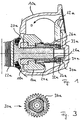
- FIGS. 1 to 3 is a disc brake shown. It has a caliper 10a. Furthermore, it has an application device to which a rotary lever 12a with a brake shaft 14a belongs. If the rotary lever is pivoted in the direction "D", it exerts pressure on a pressure piece 16a, which forms a traverse of the brake. The pressure piece 16a in turn presses on a pressure sleeve 18a, which then transmits the clamping force via a pressure screw 20a on a brake pad 22a. Therefore, upon actuation of the rotary lever 12a, the brake pad 22a is pressed against a brake disc, not shown in the drawing.
- a drive sleeve 24a is coupled to the brake shaft 14a such that a pivoting of the rotary lever 12a after overcoming a clearance leads to a rotation of the drive sleeve 24a.
- the longitudinal axis of the pin 23a is inclined relative to the axis of rotation of the brake shaft 14a, for example by 18 °. Because of the improved translation achieved thereby, a higher degree of adjustment per actuation of the brake is achieved.
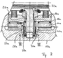
- the drive sleeve 24a is coupled to a driven sleeve 28a via a wrap spring 26a serving as a one-way clutch. As a result, the output sleeve 28a also rotates when tightening.
- the output sleeve 28a forms together with a support plate 30a a slip clutch.
- the support disk 30a rests against the output sleeve 28a with its friction surface 32a facing "inwards”.
- the output sleeve 28a in turn lies in this embodiment with a friction surface 40a (here flat) on a contact surface 38a of the pressure sleeve 18a.
- For bias serve three disc springs 33a, which are supported on a locking ring 34a.
- the support disk 30a has according to FIG. 3 an outer contour deviating from the circular shape, in the illustrated embodiment, approximately star-shaped, wherein the outer contour of the pressure sleeve 18a where the support disk 30a sits, a complementary outer contour, so that the support plate 30a is rotationally coupled to the pressure sleeve 18a in both directions of rotation.
- each other causes a pivoting of the brake lever 12a in the direction of "D" after overcoming the clearance rotation of the pressure sleeve 18a, which is screwed to the rotatably held pressure screw 20a, so that the pressure screw 20a in FIG 5 unscrewed to the left from the pressure sleeve 18a.
- the support disk 30a is according to FIG. 3 provided on its outer edge with a ring gear 36a.
- the ring gear 36a engages in the installed state in an adjustment shaft, not shown in the drawing.
- the Justierwelle is so to speak "next to" the actual adjustment, which has the advantage of lower axial length.
- the adjusting shaft may for example have a hexagonal head.
- a work opening also not shown in the drawing, is provided on the saddle 10a. The work opening can be closed with a stopper to protect against contamination.
- the adjusting shaft serves, for example, to rotate the support disk 30a and the thrust-coupled pressure sleeve 18a in order to screw the pressure screw 20a back into the pressure sleeve 18a, for example after renewal of the brake lining 22a.
- the support plate 30a itself serve as an adjustment.
- it may have on the side facing away from the brake disc a deviating from the circular shape inner contour and / or a profiling, in which a corresponding tool is to be inserted for adjusting.
- a corresponding working opening will be provided on the saddle 10a, again closed with a plug. It can also be provided to attach an adjusting tool directly to the pressure sleeve 18a.
- the support plate 30a of the coupling of the clamping causing the rotary lever 12a with the adjusting device because it sits rotationally fixed on the pressure sleeve 18a and therefore can transmit torques.
- the invention also covers solutions without such an adjusting shaft in addition to the actual adjusting device.
- the support plate 30a have a deviating from the circular shape inner contour, so that an adjustment of the adjusting device can be made directly to the support plate 30a by applying a corresponding tool.
- the invention is applicable to brakes with one, two or more compression screw (s) / - spindle (s) and brakes with and without pressure piece.
Landscapes
- Engineering & Computer Science (AREA)
- General Engineering & Computer Science (AREA)
- Mechanical Engineering (AREA)
- Braking Arrangements (AREA)
Claims (17)
- Dispositif de réglage pour freins à disques, en particulier pour véhicules utilitaires, comprenant un élément de réglage (18a) en forme d'écrou de réglage et
un accouplement à glissement (28a, 30a, 32a, 38a, 40a) pour limiter le couple pouvant être transmis à l'élément de réglage,
l'accouplement à glissement présentant un élément de friction (30a) qui est accouplé en rotation à l'élément de réglage dans les deux sens de rotation,
caractérisé en ce que l'élément de friction (30a) présente un contour interne s'écartant d'une forme circulaire et repose sur l'élément de réglage (18a) et
l'élément de réglage, à l'emplacement de l'élément de friction, présente un contour externe complémentaire, de sorte que l'élément de friction soit accouplé à rotation dans les deux sens à l'élément de réglage. - Dispositif de réglage selon la revendication 1, caractérisé en ce qu'une surface de friction (32a) de l'élément de friction (30a) formant une partie de l'accouplement à glissement (28a, 30a, 32a, 38a, 40a) est tournée vers un disque de frein dans l'état monté.
- Dispositif de réglage selon la revendication 1 ou 2, caractérisé en ce que l'élément de friction (30a) présente un dispositif d'accouplement (36a) pour l'accouplement à un dispositif d'ajustement pour l'élément de réglage (18a).
- Dispositif de réglage selon la revendication 3, caractérisé en ce que le dispositif d'accouplement (36a) présente une couronne dentée.
- Dispositif de réglage selon la revendication 3 ou 4, caractérisé en ce que le dispositif d'accouplement présente un contour interne s'écartant de la forme circulaire au niveau de l'élément de friction (30a).
- Dispositif de réglage selon l'une quelconque des revendications 3 à 5, caractérisé en ce que le dispositif d'accouplement présente un profilage sur le côté de l'élément de friction (30a) opposé au disque de frein.
- Dispositif de réglage selon l'une quelconque des revendications précédentes, caractérisé par un profilage de l'élément de réglage pour l'accouplement à un outil d'ajustement ou à un insert d'ajustement.
- Dispositif de réglage selon l'une quelconque des revendications précédentes, caractérisé par un dispositif de précontrainte (33a) pour précontraindre l'accouplement glissant (28a, 30a, 32a, 38a, 40a) dans le sens d'un accouplement par engagement par friction.
- Dispositif de réglage selon la revendication 8, caractérisé en ce que le dispositif de précontrainte (33a) présente un dispositif élastique sur le côté de l'élément de friction (30a) opposé à un disque de frein dans l'état monté.
- Dispositif de réglage selon la revendication 8 ou 9, caractérisé en ce que le dispositif de précontrainte (33a) présente un, deux ou plus de deux ressorts Belleville.
- Dispositif de réglage selon l'une quelconque des revendications précédentes, caractérisé en ce qu'une surface de friction (32a) formant une partie de l'accouplement glissant (28a, 30a, 32a, 38a, 40a) est annulaire.
- Dispositif de réglage selon l'une quelconque des revendications précédentes, caractérisé en ce qu'une surface de friction (32a) formant une partie de l'accouplement glissant (28a, 30a, 32a, 38a, 40a) est au moins en partie plane, en forme d'enveloppe de section conique ou dentée.
- Frein à disques, en particulier pour véhicules utilitaires, comprenant un dispositif de réglage selon l'une quelconque des revendications précédentes.
- Frein à disques selon la revendication 13, caractérisé en ce qu'au moins des parties du dispositif de réglage sont accouplées à une pièce de pression (16a) de telle sorte qu'elles suivent son mouvement dans la direction axiale du frein lors du serrage.
- Frein à disques selon la revendication 14, caractérisé en ce que la pièce de pression (16a) présente un contour rectangulaire.
- Frein à disques selon la revendication 14 ou 15, caractérisé en ce que la pièce de pression (16a) présente une structure de traverse.
- Frein à disques selon l'une quelconque des revendications 13 à 16, caractérisé par un dispositif d'ajustement dont l'axe de rotation ne coïncide pas avec l'axe de rotation de l'accouplement glissant (28a, 30a, 32a, 38a, 40a).
Applications Claiming Priority (3)
| Application Number | Priority Date | Filing Date | Title |
|---|---|---|---|
| DE200810037775 DE102008037775B3 (de) | 2008-08-14 | 2008-08-14 | Nachstellvorrichtung für eine Scheibenbremse, insbesondere für Nutzfahrzeuge, sowie Scheibenbremse mit einer solchen Nachstellvorrichtung |
| DE102008037774A DE102008037774C5 (de) | 2008-08-14 | 2008-08-14 | Scheibenbremse, insbesondere für Nutzfahrzeuge |
| EP09777593.6A EP2315966B2 (fr) | 2008-08-14 | 2009-07-31 | Frein à disque |
Related Parent Applications (3)
| Application Number | Title | Priority Date | Filing Date |
|---|---|---|---|
| EP09777593.6 Division | 2009-07-31 | ||
| EP09777593.6A Division-Into EP2315966B2 (fr) | 2008-08-14 | 2009-07-31 | Frein à disque |
| EP09777593.6A Division EP2315966B2 (fr) | 2008-08-14 | 2009-07-31 | Frein à disque |
Publications (3)
| Publication Number | Publication Date |
|---|---|
| EP2476929A1 EP2476929A1 (fr) | 2012-07-18 |
| EP2476929B1 EP2476929B1 (fr) | 2012-12-26 |
| EP2476929B2 true EP2476929B2 (fr) | 2016-08-03 |
Family
ID=41092125
Family Applications (2)
| Application Number | Title | Priority Date | Filing Date |
|---|---|---|---|
| EP09777593.6A Active EP2315966B2 (fr) | 2008-08-14 | 2009-07-31 | Frein à disque |
| EP10016215.5A Active EP2476929B2 (fr) | 2008-08-14 | 2009-07-31 | Dispositif de réglage pour un frein à disque |
Family Applications Before (1)
| Application Number | Title | Priority Date | Filing Date |
|---|---|---|---|
| EP09777593.6A Active EP2315966B2 (fr) | 2008-08-14 | 2009-07-31 | Frein à disque |
Country Status (5)
| Country | Link |
|---|---|
| US (2) | US8590675B2 (fr) |
| EP (2) | EP2315966B2 (fr) |
| CN (2) | CN103233991B (fr) |
| AT (1) | ATE531968T1 (fr) |
| WO (1) | WO2010017901A1 (fr) |
Families Citing this family (30)
| Publication number | Priority date | Publication date | Assignee | Title |
|---|---|---|---|---|
| DE102010011725A1 (de) | 2010-03-17 | 2011-09-22 | Haldex Brake Products Ab | Scheibenbremse und Herstellungsverfahren für eine Scheibenbremse |
| GB201110556D0 (en) * | 2011-06-22 | 2011-08-03 | Meritor Heavy Vehicle Braking | A brake |
| CN102359521B (zh) * | 2011-09-28 | 2013-04-24 | 西北工业大学 | 重型汽车盘式制动器过量间隙自调机构 |
| EP2602505A1 (fr) * | 2011-12-05 | 2013-06-12 | Meritor Heavy Vehicle Braking Systems (UK) Limited | Système de dispositif d'ajustement |
| DE102012102585B4 (de) * | 2012-03-26 | 2014-07-10 | Knorr-Bremse Systeme für Nutzfahrzeuge GmbH | Scheibenbremse für ein Nutzfahrzeug |
| DE102012006101A1 (de) * | 2012-03-26 | 2013-09-26 | Knorr-Bremse Systeme für Nutzfahrzeuge GmbH | Zuspannvorrichtung für eine Scheibenbremse |
| DE102012012472A1 (de) * | 2012-06-22 | 2013-12-24 | Knorr-Bremse Systeme für Nutzfahrzeuge GmbH | Justiervorrichtung einer Scheibenbremse und entsprechende Scheibenbremse |
| DE102012014886A1 (de) * | 2012-07-26 | 2014-01-30 | Knorr-Bremse Systeme für Nutzfahrzeuge GmbH | Zuspanneinrichtung einer Scheibenbremse für ein Nutzfahrzeug |
| WO2014021646A1 (fr) * | 2012-07-31 | 2014-02-06 | 상신브레이크 주식회사 | Frein à disque pour véhicule comprenant une broche de guidage |
| JP5845153B2 (ja) * | 2012-08-06 | 2016-01-20 | Kyb株式会社 | キャリパブレーキ装置 |
| DE102012108672B3 (de) | 2012-09-17 | 2014-02-06 | Knorr-Bremse Systeme für Nutzfahrzeuge GmbH | Nachstelleinrichtung einer Scheibenbremse, eine entsprechende Scheibenbremse und Verfahren zum Betreiben einer Verschleißnachstellvorrichtung einer Scheibenbremse |
| GB2522641B (en) * | 2014-01-30 | 2016-03-09 | Newbridge Brake Ltd | Brake caliper |
| DE102014101341A1 (de) * | 2014-02-04 | 2015-08-06 | Bpw Bergische Achsen Kg | Fahrzeugbremse, insbesondere Fahrzeug-Scheibenbremse |
| GB2523141C (en) * | 2014-02-14 | 2020-12-02 | Newbridge Brake Ltd | Disc brake caliper |
| US10066692B2 (en) * | 2014-04-04 | 2018-09-04 | Haldex Brake Products Ab | Brake actuation mechanism for a disc brake and disc brake comprising the same |
| DE102014017430A1 (de) * | 2014-11-25 | 2016-05-25 | Wabco Europe Bvba | Scheibenbremse, insbesondere für Nutzfahrzeuge |
| CN105782298B (zh) * | 2014-12-16 | 2018-05-25 | 陕西华臻汽车零部件有限公司 | 车辆用盘式制动器间隙自调整机构及自调整方法 |
| DE102015100322A1 (de) * | 2015-01-12 | 2016-07-14 | Bpw Bergische Achsen Kg | Scheibenbremse sowie Antriebselement einer Nachstelleinrichtung einer Scheibenbremse |
| EP3051169A1 (fr) | 2015-01-28 | 2016-08-03 | Meritor Heavy Vehicle Braking Systems (UK) Limited | Frein à disque |
| EP3109499B1 (fr) * | 2015-06-23 | 2019-12-25 | WABCO Europe BVBA | Frein a disque, en particulier pour vehicules utilitaires |
| DE102015114546A1 (de) * | 2015-09-01 | 2017-03-02 | Knorr-Bremse Systeme für Nutzfahrzeuge GmbH | Scheibenbremse für ein Fahrzeug, insbesondere für ein Nutzfahrzeug |
| EP3184386B2 (fr) * | 2015-12-22 | 2024-04-10 | Haldex Brake Products AB | Câble et son procédé de fabrication |
| US9915305B2 (en) * | 2016-06-08 | 2018-03-13 | Deere & Company | Retention pin having foot for holding spring in disc brake pack reaction plate during assembly and for operating stator disc |
| EP3260721B8 (fr) | 2016-06-21 | 2021-06-02 | ZF CV Systems Europe BV | Unité de réglage pour un frein à disque de véhicule et ledit frein |
| DE102017005027B4 (de) * | 2017-05-26 | 2019-03-14 | Haldex Brake Products Ab | Scheibenbremse und Bremsbetätigungsmechanismus |
| JP6746789B2 (ja) * | 2017-06-30 | 2020-08-26 | 日立オートモティブシステムズ株式会社 | ディスクブレーキ |
| EP3564549A1 (fr) * | 2018-04-30 | 2019-11-06 | Meritor Heavy Vehicle Braking Systems (UK) Limited | Frein à disque |
| EP3564552B1 (fr) * | 2018-04-30 | 2021-06-02 | Meritor Heavy Vehicle Braking Systems (UK) Limited | Mécanisme d'actionnement |
| DE102019209529B4 (de) | 2019-06-28 | 2021-05-06 | Continental Teves Ag & Co. Ohg | Lamellenbremse für ein drehbares Element |
| EP3772599B1 (fr) * | 2019-08-05 | 2024-05-01 | ZF CV Systems Europe BV | Étrier de frein pour un frein de véhicule et procédé d'assemblage d'un étrier de frein |
Citations (3)
| Publication number | Priority date | Publication date | Assignee | Title |
|---|---|---|---|---|
| DE19632917A1 (de) † | 1995-08-18 | 1997-02-20 | Lucas Ind Plc | Bremsenjustiermechanismus |
| EP1596092A1 (fr) † | 2004-05-13 | 2005-11-16 | Meritor Heavy Vehicle Braking Systems (UK) Limited | Indicateur d'usure de garniture de frein. |
| WO2006111136A1 (fr) † | 2005-04-20 | 2006-10-26 | Bpw Bergische Achsen Kg | Frein sur roue |
Family Cites Families (24)
| Publication number | Priority date | Publication date | Assignee | Title |
|---|---|---|---|---|
| US3497036A (en) * | 1966-11-15 | 1970-02-24 | Teves Gmbh Alfred | Wheel-brake cylinder with piston-stop means |
| US3967705A (en) * | 1975-04-02 | 1976-07-06 | The Bendix Corporation | Application adjuster for disc brake |
| JPS55163339A (en) * | 1979-05-31 | 1980-12-19 | Toyota Motor Corp | Automatic adjusting mechanism of disc brake |
| DE3713201A1 (de) | 1987-04-18 | 1988-10-27 | Teves Gmbh Alfred | Nachstellvorrichtung fuer eine teilbelag-scheibenbremse |
| DE4204307A1 (de) | 1992-02-13 | 1993-08-19 | Knorr Bremse Ag | Drehantrieb fuer eine stellspindel einer scheibenbremse fuer fahrzeuge |
| DE4231560C2 (de) * | 1992-09-21 | 2002-07-11 | Perrot Bremse Gmbh Deutsche | Betätigungsvorrichtung für eine Gleitsattel-Scheibenbremse |
| DE4307018A1 (de) * | 1993-03-05 | 1994-09-08 | Perrot Bremse Gmbh Deutsche | Nachstellvorrichtung für eine Scheibenbremse |
| DE4323292A1 (de) | 1993-07-12 | 1995-01-19 | Perrot Bremse Gmbh Deutsche | Nachstellvorrichtung für eine Scheibenbremse |
| JPH09507559A (ja) * | 1994-01-18 | 1997-07-29 | ルーカス・インダストリーズ・パブリック・リミテッド・カンパニー | 特に重車両用のディスクブレーキのパッド押しつけ装置 |
| US5625723A (en) | 1995-02-28 | 1997-04-29 | Lucent Technologies Inc. | Method for reducing birefringence in optical gratings |
| DE19507308A1 (de) * | 1995-03-02 | 1996-09-05 | Perrot Bremsen Gmbh | Scheibenbremse |
| US5794738A (en) | 1996-11-12 | 1998-08-18 | Rockwell Heavy Vehicle Systems, Inc. | Disc brake with gear driven adjusting piston |
| DE19654729A1 (de) | 1996-12-30 | 1999-07-22 | Bosch Gmbh Robert | Elektromotorische Bremsvorrichtung |
| SE511562C2 (sv) * | 1997-04-28 | 1999-10-18 | Volvo Lastvagnar Ab | Justeranordning avseende förslitning av bromsbelägg |
| FR2826418B1 (fr) * | 2001-06-21 | 2005-01-28 | Bosch Gmbh Robert | Frein a disque pour vehicule a convertisseur de mouvement |
| DE10233673A1 (de) * | 2001-07-31 | 2003-03-20 | Tokico Ltd | Elektrische Bremsvorrichtung |
| EP1638986A1 (fr) | 2001-11-05 | 2006-03-29 | Curagen Corporation | Nouvelles proteines et acides nucleiques les codant |
| DE10214670B4 (de) | 2002-04-03 | 2014-01-23 | Knorr-Bremse Systeme für Schienenfahrzeuge GmbH | Bremszuspanneinrichtung mit elektrisch betätigtem Verschleißnachsteller |
| NO318393B1 (no) | 2002-11-12 | 2005-03-14 | Sinvent As | Fremgangsmate og system for transport av hydrokarbonstrommer som inneholder voks og asfaltener |
| AU2003292256A1 (en) * | 2002-12-23 | 2004-07-22 | Haldex Brake Products Ab | Brake gear for a disc brake |
| DE102005003223B4 (de) * | 2005-01-24 | 2007-02-01 | Haldex Brake Products Ab | Scheibenbremse mit Nachstelleinrichtung |
| DE102005018157B4 (de) * | 2005-04-20 | 2019-04-18 | Bpw Bergische Achsen Kg | Radbremse |
| DE102006020550B4 (de) * | 2006-05-03 | 2013-11-28 | Haldex Brake Products Ab | Bremsmechanismus für eine Scheibenbremse |
| DE102007007493B4 (de) | 2007-02-15 | 2018-12-13 | Bpw Bergische Achsen Kg | Zustelleinrichtung für eine Fahrzeug-Scheibenbremse |
-
2009
- 2009-07-31 CN CN201310166343.0A patent/CN103233991B/zh active Active
- 2009-07-31 EP EP09777593.6A patent/EP2315966B2/fr active Active
- 2009-07-31 WO PCT/EP2009/005581 patent/WO2010017901A1/fr not_active Ceased
- 2009-07-31 AT AT09777593T patent/ATE531968T1/de active
- 2009-07-31 CN CN200980131174.9A patent/CN102119288B/zh active Active
- 2009-07-31 EP EP10016215.5A patent/EP2476929B2/fr active Active
- 2009-07-31 US US13/058,186 patent/US8590675B2/en active Active
-
2013
- 2013-10-24 US US14/062,214 patent/US9453545B2/en active Active
Patent Citations (3)
| Publication number | Priority date | Publication date | Assignee | Title |
|---|---|---|---|---|
| DE19632917A1 (de) † | 1995-08-18 | 1997-02-20 | Lucas Ind Plc | Bremsenjustiermechanismus |
| EP1596092A1 (fr) † | 2004-05-13 | 2005-11-16 | Meritor Heavy Vehicle Braking Systems (UK) Limited | Indicateur d'usure de garniture de frein. |
| WO2006111136A1 (fr) † | 2005-04-20 | 2006-10-26 | Bpw Bergische Achsen Kg | Frein sur roue |
Also Published As
| Publication number | Publication date |
|---|---|
| US9453545B2 (en) | 2016-09-27 |
| US20110147138A1 (en) | 2011-06-23 |
| WO2010017901A1 (fr) | 2010-02-18 |
| EP2315966A1 (fr) | 2011-05-04 |
| EP2315966B2 (fr) | 2016-03-16 |
| CN102119288A (zh) | 2011-07-06 |
| CN103233991B (zh) | 2015-08-26 |
| US20140048358A1 (en) | 2014-02-20 |
| EP2315966B1 (fr) | 2011-11-02 |
| EP2476929A1 (fr) | 2012-07-18 |
| US8590675B2 (en) | 2013-11-26 |
| EP2476929B1 (fr) | 2012-12-26 |
| CN102119288B (zh) | 2014-02-19 |
| ATE531968T1 (de) | 2011-11-15 |
| CN103233991A (zh) | 2013-08-07 |
Similar Documents
| Publication | Publication Date | Title |
|---|---|---|
| EP2476929B2 (fr) | Dispositif de réglage pour un frein à disque | |
| DE102008037774B3 (de) | Scheibenbremse, insbesondere für Nutzfahrzeuge | |
| EP3271604B1 (fr) | Frein à disque pour véhicule utilitaire | |
| EP0271864B1 (fr) | Mécanisme d'actionnement à réajustage automatique pour freins, en particulier pour véhicules poids lourd | |
| DE102014113826B4 (de) | Nachstelleinrichtung einer Scheibenbremse, und eine entsprechende Scheibenbremse | |
| EP0730107A2 (fr) | Frein à disque | |
| DE102014017438A1 (de) | Scheibenbremse. insbesondere für Nutzfahrzeuge | |
| EP3224497A1 (fr) | Frein à disque destiné notamment à des véhicules utilitaires | |
| EP2831464B1 (fr) | Dispositif d'application d'effort pour un frein à disque actionné par un levier rotatif | |
| EP3700710B1 (fr) | Dispositif de serrage et machine-outil manuelle | |
| EP3202533A1 (fr) | Dispositif de serrage | |
| DE102008037775B3 (de) | Nachstellvorrichtung für eine Scheibenbremse, insbesondere für Nutzfahrzeuge, sowie Scheibenbremse mit einer solchen Nachstellvorrichtung | |
| DE102013103064B4 (de) | Nachstelleinrichtung für eine Scheibenbremse und eine entsprechende Scheibenbremse | |
| DE102014113055A1 (de) | Nachstellvorrichtung für eine drehhebelbetätigte Scheibenbremse, und Scheibenbremse mit einer solchen Nachstellvorrichtung | |
| EP2292945B1 (fr) | Frein à disque doté d'un accouplement à patinage pour le dispositif de réglage | |
| EP2052900B1 (fr) | Agencement d'engrenage | |
| DE2218929A1 (de) | Nachstellvorrichtung | |
| DE102006041660B4 (de) | Stellvorrichtung zur linearen Verstellung eines Stellgliedes | |
| DE3142799A1 (de) | Mechanisch betaetigte gleitsattel-scheibenbremse | |
| EP2927775B1 (fr) | Dispositif d'actionnement pour un système de freinage ou d'embrayage | |
| EP3867544B1 (fr) | Frein à disque | |
| WO2020002052A1 (fr) | Frein à disque pour véhicule utilitaire | |
| DE3213835A1 (de) | Ueberlastkupplung fuer drehuebertragungen | |
| EP3542082B1 (fr) | Dispositif de rattrapage d'usure pour frein à disque | |
| EP3510300B1 (fr) | Dispositif de rattrapage de jeu pour système de freinage |
Legal Events
| Date | Code | Title | Description |
|---|---|---|---|
| PUAI | Public reference made under article 153(3) epc to a published international application that has entered the european phase |
Free format text: ORIGINAL CODE: 0009012 |
|
| 17P | Request for examination filed |
Effective date: 20101230 |
|
| AC | Divisional application: reference to earlier application |
Ref document number: 2315966 Country of ref document: EP Kind code of ref document: P |
|
| AK | Designated contracting states |
Kind code of ref document: A1 Designated state(s): AT BE BG CH CY CZ DE DK EE ES FI FR GB GR HR HU IE IS IT LI LT LU LV MC MK MT NL NO PL PT RO SE SI SK SM TR |
|
| GRAP | Despatch of communication of intention to grant a patent |
Free format text: ORIGINAL CODE: EPIDOSNIGR1 |
|
| GRAS | Grant fee paid |
Free format text: ORIGINAL CODE: EPIDOSNIGR3 |
|
| GRAA | (expected) grant |
Free format text: ORIGINAL CODE: 0009210 |
|
| AC | Divisional application: reference to earlier application |
Ref document number: 2315966 Country of ref document: EP Kind code of ref document: P |
|
| AK | Designated contracting states |
Kind code of ref document: B1 Designated state(s): AT BE BG CH CY CZ DE DK EE ES FI FR GB GR HR HU IE IS IT LI LT LU LV MC MK MT NL NO PL PT RO SE SI SK SM TR |
|
| REG | Reference to a national code |
Ref country code: GB Ref legal event code: FG4D Free format text: NOT ENGLISH |
|
| REG | Reference to a national code |
Ref country code: CH Ref legal event code: EP |
|
| REG | Reference to a national code |
Ref country code: AT Ref legal event code: REF Ref document number: 590655 Country of ref document: AT Kind code of ref document: T Effective date: 20130115 |
|
| REG | Reference to a national code |
Ref country code: DE Ref legal event code: R096 Ref document number: 502009005835 Country of ref document: DE Effective date: 20130307 |
|
| REG | Reference to a national code |
Ref country code: SE Ref legal event code: TRGR |
|
| PG25 | Lapsed in a contracting state [announced via postgrant information from national office to epo] |
Ref country code: FI Free format text: LAPSE BECAUSE OF FAILURE TO SUBMIT A TRANSLATION OF THE DESCRIPTION OR TO PAY THE FEE WITHIN THE PRESCRIBED TIME-LIMIT Effective date: 20121226 Ref country code: LT Free format text: LAPSE BECAUSE OF FAILURE TO SUBMIT A TRANSLATION OF THE DESCRIPTION OR TO PAY THE FEE WITHIN THE PRESCRIBED TIME-LIMIT Effective date: 20121226 Ref country code: HR Free format text: LAPSE BECAUSE OF FAILURE TO SUBMIT A TRANSLATION OF THE DESCRIPTION OR TO PAY THE FEE WITHIN THE PRESCRIBED TIME-LIMIT Effective date: 20121226 Ref country code: NO Free format text: LAPSE BECAUSE OF FAILURE TO SUBMIT A TRANSLATION OF THE DESCRIPTION OR TO PAY THE FEE WITHIN THE PRESCRIBED TIME-LIMIT Effective date: 20130326 |
|
| REG | Reference to a national code |
Ref country code: LT Ref legal event code: MG4D |
|
| REG | Reference to a national code |
Ref country code: NL Ref legal event code: VDEP Effective date: 20121226 |
|
| PG25 | Lapsed in a contracting state [announced via postgrant information from national office to epo] |
Ref country code: SI Free format text: LAPSE BECAUSE OF FAILURE TO SUBMIT A TRANSLATION OF THE DESCRIPTION OR TO PAY THE FEE WITHIN THE PRESCRIBED TIME-LIMIT Effective date: 20121226 Ref country code: LV Free format text: LAPSE BECAUSE OF FAILURE TO SUBMIT A TRANSLATION OF THE DESCRIPTION OR TO PAY THE FEE WITHIN THE PRESCRIBED TIME-LIMIT Effective date: 20121226 Ref country code: GR Free format text: LAPSE BECAUSE OF FAILURE TO SUBMIT A TRANSLATION OF THE DESCRIPTION OR TO PAY THE FEE WITHIN THE PRESCRIBED TIME-LIMIT Effective date: 20130327 |
|
| PG25 | Lapsed in a contracting state [announced via postgrant information from national office to epo] |
Ref country code: IS Free format text: LAPSE BECAUSE OF FAILURE TO SUBMIT A TRANSLATION OF THE DESCRIPTION OR TO PAY THE FEE WITHIN THE PRESCRIBED TIME-LIMIT Effective date: 20130426 Ref country code: BG Free format text: LAPSE BECAUSE OF FAILURE TO SUBMIT A TRANSLATION OF THE DESCRIPTION OR TO PAY THE FEE WITHIN THE PRESCRIBED TIME-LIMIT Effective date: 20130326 Ref country code: CZ Free format text: LAPSE BECAUSE OF FAILURE TO SUBMIT A TRANSLATION OF THE DESCRIPTION OR TO PAY THE FEE WITHIN THE PRESCRIBED TIME-LIMIT Effective date: 20121226 Ref country code: ES Free format text: LAPSE BECAUSE OF FAILURE TO SUBMIT A TRANSLATION OF THE DESCRIPTION OR TO PAY THE FEE WITHIN THE PRESCRIBED TIME-LIMIT Effective date: 20130406 Ref country code: EE Free format text: LAPSE BECAUSE OF FAILURE TO SUBMIT A TRANSLATION OF THE DESCRIPTION OR TO PAY THE FEE WITHIN THE PRESCRIBED TIME-LIMIT Effective date: 20121226 Ref country code: SK Free format text: LAPSE BECAUSE OF FAILURE TO SUBMIT A TRANSLATION OF THE DESCRIPTION OR TO PAY THE FEE WITHIN THE PRESCRIBED TIME-LIMIT Effective date: 20121226 |
|
| PG25 | Lapsed in a contracting state [announced via postgrant information from national office to epo] |
Ref country code: RO Free format text: LAPSE BECAUSE OF FAILURE TO SUBMIT A TRANSLATION OF THE DESCRIPTION OR TO PAY THE FEE WITHIN THE PRESCRIBED TIME-LIMIT Effective date: 20121226 Ref country code: PL Free format text: LAPSE BECAUSE OF FAILURE TO SUBMIT A TRANSLATION OF THE DESCRIPTION OR TO PAY THE FEE WITHIN THE PRESCRIBED TIME-LIMIT Effective date: 20121226 Ref country code: PT Free format text: LAPSE BECAUSE OF FAILURE TO SUBMIT A TRANSLATION OF THE DESCRIPTION OR TO PAY THE FEE WITHIN THE PRESCRIBED TIME-LIMIT Effective date: 20130426 Ref country code: NL Free format text: LAPSE BECAUSE OF FAILURE TO SUBMIT A TRANSLATION OF THE DESCRIPTION OR TO PAY THE FEE WITHIN THE PRESCRIBED TIME-LIMIT Effective date: 20121226 |
|
| PLBI | Opposition filed |
Free format text: ORIGINAL CODE: 0009260 |
|
| 26 | Opposition filed |
Opponent name: KNORR-BREMSE SYSTEME FUER NUTZFAHRZEUGE GMBH Effective date: 20130925 |
|
| PG25 | Lapsed in a contracting state [announced via postgrant information from national office to epo] |
Ref country code: DK Free format text: LAPSE BECAUSE OF FAILURE TO SUBMIT A TRANSLATION OF THE DESCRIPTION OR TO PAY THE FEE WITHIN THE PRESCRIBED TIME-LIMIT Effective date: 20121226 |
|
| PLAX | Notice of opposition and request to file observation + time limit sent |
Free format text: ORIGINAL CODE: EPIDOSNOBS2 |
|
| PG25 | Lapsed in a contracting state [announced via postgrant information from national office to epo] |
Ref country code: CY Free format text: LAPSE BECAUSE OF FAILURE TO SUBMIT A TRANSLATION OF THE DESCRIPTION OR TO PAY THE FEE WITHIN THE PRESCRIBED TIME-LIMIT Effective date: 20121226 |
|
| REG | Reference to a national code |
Ref country code: DE Ref legal event code: R026 Ref document number: 502009005835 Country of ref document: DE Effective date: 20130925 |
|
| BERE | Be: lapsed |
Owner name: WABCO RADBREMSEN G.M.B.H. Effective date: 20130731 |
|
| PG25 | Lapsed in a contracting state [announced via postgrant information from national office to epo] |
Ref country code: MC Free format text: LAPSE BECAUSE OF FAILURE TO SUBMIT A TRANSLATION OF THE DESCRIPTION OR TO PAY THE FEE WITHIN THE PRESCRIBED TIME-LIMIT Effective date: 20121226 |
|
| REG | Reference to a national code |
Ref country code: CH Ref legal event code: PL |
|
| PLBB | Reply of patent proprietor to notice(s) of opposition received |
Free format text: ORIGINAL CODE: EPIDOSNOBS3 |
|
| REG | Reference to a national code |
Ref country code: IE Ref legal event code: MM4A |
|
| PG25 | Lapsed in a contracting state [announced via postgrant information from national office to epo] |
Ref country code: BE Free format text: LAPSE BECAUSE OF NON-PAYMENT OF DUE FEES Effective date: 20130731 Ref country code: CH Free format text: LAPSE BECAUSE OF NON-PAYMENT OF DUE FEES Effective date: 20130731 Ref country code: LI Free format text: LAPSE BECAUSE OF NON-PAYMENT OF DUE FEES Effective date: 20130731 |
|
| PG25 | Lapsed in a contracting state [announced via postgrant information from national office to epo] |
Ref country code: IE Free format text: LAPSE BECAUSE OF NON-PAYMENT OF DUE FEES Effective date: 20130731 |
|
| PG25 | Lapsed in a contracting state [announced via postgrant information from national office to epo] |
Ref country code: SM Free format text: LAPSE BECAUSE OF FAILURE TO SUBMIT A TRANSLATION OF THE DESCRIPTION OR TO PAY THE FEE WITHIN THE PRESCRIBED TIME-LIMIT Effective date: 20121226 |
|
| PG25 | Lapsed in a contracting state [announced via postgrant information from national office to epo] |
Ref country code: MT Free format text: LAPSE BECAUSE OF FAILURE TO SUBMIT A TRANSLATION OF THE DESCRIPTION OR TO PAY THE FEE WITHIN THE PRESCRIBED TIME-LIMIT Effective date: 20121226 Ref country code: TR Free format text: LAPSE BECAUSE OF FAILURE TO SUBMIT A TRANSLATION OF THE DESCRIPTION OR TO PAY THE FEE WITHIN THE PRESCRIBED TIME-LIMIT Effective date: 20121226 |
|
| REG | Reference to a national code |
Ref country code: FR Ref legal event code: PLFP Year of fee payment: 7 |
|
| PG25 | Lapsed in a contracting state [announced via postgrant information from national office to epo] |
Ref country code: HU Free format text: LAPSE BECAUSE OF FAILURE TO SUBMIT A TRANSLATION OF THE DESCRIPTION OR TO PAY THE FEE WITHIN THE PRESCRIBED TIME-LIMIT; INVALID AB INITIO Effective date: 20090731 Ref country code: MK Free format text: LAPSE BECAUSE OF FAILURE TO SUBMIT A TRANSLATION OF THE DESCRIPTION OR TO PAY THE FEE WITHIN THE PRESCRIBED TIME-LIMIT Effective date: 20121226 Ref country code: LU Free format text: LAPSE BECAUSE OF NON-PAYMENT OF DUE FEES Effective date: 20130731 |
|
| REG | Reference to a national code |
Ref country code: AT Ref legal event code: MM01 Ref document number: 590655 Country of ref document: AT Kind code of ref document: T Effective date: 20140731 |
|
| PG25 | Lapsed in a contracting state [announced via postgrant information from national office to epo] |
Ref country code: AT Free format text: LAPSE BECAUSE OF NON-PAYMENT OF DUE FEES Effective date: 20140731 |
|
| PUAH | Patent maintained in amended form |
Free format text: ORIGINAL CODE: 0009272 |
|
| STAA | Information on the status of an ep patent application or granted ep patent |
Free format text: STATUS: PATENT MAINTAINED AS AMENDED |
|
| RAP2 | Party data changed (patent owner data changed or rights of a patent transferred) |
Owner name: WABCO EUROPE BVBA |
|
| REG | Reference to a national code |
Ref country code: FR Ref legal event code: PLFP Year of fee payment: 8 |
|
| 27A | Patent maintained in amended form |
Effective date: 20160803 |
|
| AK | Designated contracting states |
Kind code of ref document: B2 Designated state(s): AT BE BG CH CY CZ DE DK EE ES FI FR GB GR HR HU IE IS IT LI LT LU LV MC MK MT NL NO PL PT RO SE SI SK SM TR |
|
| REG | Reference to a national code |
Ref country code: DE Ref legal event code: R102 Ref document number: 502009005835 Country of ref document: DE |
|
| REG | Reference to a national code |
Ref country code: SE Ref legal event code: RPEO |
|
| REG | Reference to a national code |
Ref country code: FR Ref legal event code: PLFP Year of fee payment: 9 |
|
| REG | Reference to a national code |
Ref country code: GB Ref legal event code: 732E Free format text: REGISTERED BETWEEN 20180524 AND 20180530 |
|
| REG | Reference to a national code |
Ref country code: FR Ref legal event code: PLFP Year of fee payment: 10 |
|
| P01 | Opt-out of the competence of the unified patent court (upc) registered |
Effective date: 20230528 |
|
| PGFP | Annual fee paid to national office [announced via postgrant information from national office to epo] |
Ref country code: FR Payment date: 20240611 Year of fee payment: 16 |
|
| PGFP | Annual fee paid to national office [announced via postgrant information from national office to epo] |
Ref country code: IT Payment date: 20240612 Year of fee payment: 16 |
|
| REG | Reference to a national code |
Ref country code: DE Ref legal event code: R082 Ref document number: 502009005835 Country of ref document: DE Ref country code: DE Ref legal event code: R081 Ref document number: 502009005835 Country of ref document: DE Owner name: ZF CV SYSTEMS EUROPE BV, BE Free format text: FORMER OWNER: WABCO RADBREMSEN GMBH, 68229 MANNHEIM, DE |
|
| PGFP | Annual fee paid to national office [announced via postgrant information from national office to epo] |
Ref country code: GB Payment date: 20250612 Year of fee payment: 17 |
|
| PGFP | Annual fee paid to national office [announced via postgrant information from national office to epo] |
Ref country code: SE Payment date: 20250610 Year of fee payment: 17 |
|
| PGFP | Annual fee paid to national office [announced via postgrant information from national office to epo] |
Ref country code: DE Payment date: 20250604 Year of fee payment: 17 |
|
| PG25 | Lapsed in a contracting state [announced via postgrant information from national office to epo] |
Ref country code: FR Free format text: LAPSE BECAUSE OF NON-PAYMENT OF DUE FEES Effective date: 20250731 |