EP2476959A2 - Procédé de fabrication d'une cuisinière au gaz et agencement d'une cuisinière au gaz - Google Patents
Procédé de fabrication d'une cuisinière au gaz et agencement d'une cuisinière au gaz Download PDFInfo
- Publication number
- EP2476959A2 EP2476959A2 EP11196032A EP11196032A EP2476959A2 EP 2476959 A2 EP2476959 A2 EP 2476959A2 EP 11196032 A EP11196032 A EP 11196032A EP 11196032 A EP11196032 A EP 11196032A EP 2476959 A2 EP2476959 A2 EP 2476959A2
- Authority
- EP
- European Patent Office
- Prior art keywords
- gas
- pot
- hob
- series
- discs
- Prior art date
- Legal status (The legal status is an assumption and is not a legal conclusion. Google has not performed a legal analysis and makes no representation as to the accuracy of the status listed.)
- Withdrawn
Links
Images


Classifications
-
- F—MECHANICAL ENGINEERING; LIGHTING; HEATING; WEAPONS; BLASTING
- F24—HEATING; RANGES; VENTILATING
- F24C—DOMESTIC STOVES OR RANGES ; DETAILS OF DOMESTIC STOVES OR RANGES, OF GENERAL APPLICATION
- F24C15/00—Details
- F24C15/10—Tops, e.g. hot plates; Rings
- F24C15/107—Pan supports or grates therefor
Definitions
- the present invention relates to a method of manufacturing a series or series of gas hobs. Furthermore, the invention relates to a gas hob arrangement.
- Gas hobs are produced, for example, as part of stoves or as integratable gas hobs in kitchen worktops.
- Several gas burners are arranged in a hob plate, which can be controlled via controls.
- pot carriers are provided to keep the cooking containers, such as pans or pots, at a suitable distance from the burner flame.
- the pot carriers are usually connected to the gas hob and create a support surface for food containers.
- the hob plates are made of glass-ceramic and are printed in color or with patterns or brand names in order to make them distinguishable from competitive products.
- series or rows of gas hobs from each other visually, on the one hand is used on a printing of the hob plate, and on the other hand, various embodiments of pot carriers are used.
- the user then connects with the configuration of the pot carrier, for example, a brand for the gas hobs. Since the structural individual elements of gas cooktops are constructed similarly or identically, even with different gas hob series, it is desirable to be able to use identical elements as possible in a production process. For example, it is disadvantageous to have to have different cooking field plates available or to fasten pot carriers for different gas hob series in different ways.
- an object of the present invention is to provide an improved method for producing gas hobs.
- a method for producing a gas hob series of gas hobs comprises the steps of providing a Cooktop panel with gas burners arranged on or in openings and polygonal panes arranged in areas of the gas burners; Providing a plurality of pot carriers, wherein a respective pot carrier comprises a frame which is at least partially form-fitting placed on one of the discs; Selecting a pot carrier from the plurality of pot carriers; and placing the selected pot carrier on at least one of the panes.
- the method makes it possible, in particular, for the hob plate to be made the same for all gas hob series.
- a differentiation of the series with each other is done in particular by the selection of the pot carrier and the type and aesthetic appearance of the pot carrier.
- a gas cooker range is essentially understood to mean several gas hobs that have a (branded) uniform appearance.
- the pot carrier type is used for differentiation in the proposed manufacturing process.
- pot carrier which each have a frame for positive placement on one of the (mounting) discs for all gas hobs of the gas hob series in the same way.
- This simple way of fixing allows a particularly efficient production of gas hobs.
- the pot carriers can be replaced from series to series without significantly changing the manufacturing process. In this respect, the production of a gas hob arrangement with several gas hob series is achieved particularly easily.
- a gas hob arrangement is proposed with several gas hob series of gas hobs, wherein a gas hob each comprises a cooktop with arranged on or in openings gas burners and arranged in areas of the gas burner polygonal slices, and at least partially positively on the discs patch pot carrier.
- the pan supports of various gas hob series are designed differently.
- the steps of selecting and arranging the pot carrier for producing a gas hob of a gas hob series are repeated several times performed to populate all gas burners and discs of the hob plate with pot carriers.
- all slices have the same size and shape.
- the discs are designed the same for different gas hob series.
- the discs each comprise a central opening for the arrangement of the gas burner.
- the gas burners are preferably designed the same for a respective gas hob series.
- the discs are formed, for example, as heat shields for thermal shielding of the hob plate.
- the pot carriers are preferably placed in a form-fitting manner on the heat shields.
- the heat shield can thus be used in the manner of a polygonal disk for thermal shielding from a heat of the gas burner.
- the preferably rectangular and in particular square executed heat shields allow reliable shielding of the hob plate on the one hand and on the other hand, a simple mounting the pot carrier.
- the polygonal discs or heat shields are preferably made with a smooth surface and no indentations or lugs along their peripheral edges.
- the pot carriers are manufactured in such a way that they comprise a preferably polygonal frame which can each circulate a polygonal heat shield. Another fixation is usually not necessary for the pot carrier. Thus, the fixation for all hobs of different series can be the same.
- the steps of providing a hob plate, selecting a pot carrier and arranging the selected pot carrier for producing a plurality of gas hobs of a gas hob series are repeatedly performed.
- the plurality of pot carriers comprises different groups of pot carriers, and a group of pot carriers is in each case a gas cooking field series assigned. Then, preferably, the respective pot carrier is selected as a function of the gas hob series from one of the groups.
- groups of cast iron pot carriers can be assigned to a first gas hob series and stainless steel pot carriers of a group for a second gas hob series.
- the groups can be formed, for example, by the material selection for the pot carrier, the color or its geometry.
- At least one selected pot carrier can be arranged in such a way that the pot carrier covers a plurality of gas burners.
- Such multiple pot carriers comprise, for example, a frame which partially encloses several of the polygonal disks in a form-fitting manner.
- the pot supports have so far polygonal frame and on the respective polygonal disk these are slipped and twist-proof.
- the hob plate is at least partially made of hard glass or glass ceramic in one embodiment.
- the hob plate is at least partially made of hard glass or glass ceramic. These materials allow a particularly attractive aesthetic appearance of a gas hob. In particular, only slight deformations of hard glass or glass ceramic result from temperature changes during operation of the gas burners.
- the step of providing a cooktop panel further comprises: providing a metal sheet in the manner of a well and attaching a hard glass or glass ceramic plate to a bottom surface of the metal sheet to stabilize the metal sheet against temperature variations.
- the hob plate can also be at least partially made of a metal sheet in the manner of a trough.
- the metal sheet is glued underneath with a hard glass or glass ceramic plate.
- the hard glass or glass ceramic plate largely prevents deformation as a function of temperature changes of the metal sheet.
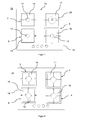
- FIG. 1 shows a flowchart for producing series or series of gas hobs. Gas hobs are also known for gas hobs of similar or similar design.
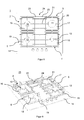
- FIGS. 2 to 5 shows a first embodiment of a gas hob according to a gas hob series shown.
- the show Figures 2 and 4 a perspective view and the Figures 3 and 5 a top view.
- the gas hob 1 is manufactured as a built-in hob with a hob plate 14, for example made of glass or glass ceramic.
- a hob plate 14 for example made of glass or glass ceramic.
- openings for four gas burners 10, 11, 12, 13 are provided, which can be controlled in terms of their performance via controls 15.
- the Figures 3 and 5 one recognizes the rectangular shape of the hob plate 14 and the gas burners 10, 11, 12, 13 usually arranged in the four quadrants.
- the disks 16, 17, 18, 19 are designed, for example, to protect the glass ceramic plate 14 as heat shields 16, 17, 18, 19.
- the heat shields 16, 17, 18, 19 are made of metal, for example, and have a square outline.
- the heat shields 16, 17, 18, 19 also have an opening so that the gas burner 10 - 13 or other fittings from a bottom of the hob plate 14 on the top, so the actual gas hob 1 can extend.
- the heat shields 16, 17, 18, 19 prevent in particular that heat reflected from the food container is reflected back directly onto the hob plate 14 and could damage it.
- the geometry of the heat shields 16, 17, 18, 19 allows a safe placement of pot carriers 2, 3, 4.
- the pot carriers 2, 3, 4 are made for example of metal and serve on the one hand to form a support surface 25 for a food container above the respective Gas burner and on the other hand forming a storage area 24 adjacent to the gas burners.
- the pot supports 2, 3, 4 each have a rectangular frame 20 which can be placed in a form-fitting manner on the heat shields 16, 17, 18, 19, which are of similar design, for example. This results in a torsion-proof and non-slip fixation in the region of the gas burners 10, 11, 12, 13.
- the quadrangular frame 20 lies flat on the glass ceramic plate 14 and forms a base 26 of the respective pot support 2, 3, 4, 5. Fingers 21 spaced vertically from the frame 20 project inwardly toward the respective gas burner 10 - 13. The tops of the fingers 21 form the support surface 25 for a food container, such as a pot or pan.
- the pot carrier elements 2, 3 also include outwardly directed fingers 22, whose upper side serve to form a shelf 24.
- support fingers 23 are also provided on the frame 20.
- the support fingers 23 are also on the surface of the glass ceramic plate 14.
- a shelf 24 is formed in the area between the burners 10, 11 thus a shelf 24 is formed.
- the shelf 24 is, as in the FIGS. 1 and 2 is indicated by created between the gas burner areas extending struts.
- the struts are piecewise assembled.
- a differentiation of gas hobs for different series or gas hob series is done in particular by the selection of the pot carrier 2, 3, 4, 5.
- In founded is for example for producing a gas hob, as in the FIGS. 2 to 5 is shown, in a first step S1, a hob plate 14 is provided.
- the hob plate 14 is provided with openings in the gas burner 10 - 13 are arranged.
- the cooktop panels 14 are provided in the areas of the gas burner 10 - 13 with the polygonal discs 16, 17, 18, 19.
- This step S1 can be carried out for all gas hobs of different series with the same components, such as cooktops, burners and slices.
- a plurality of pot carriers is provided in step S2.
- All pot carriers include a frame 20 which is at least partially form-fitting manner on the discs 16 - 19 can be placed. It forms groups of pot carriers, each gas hob series is assigned to a group of pot carriers or a respective group of pot carriers is assigned to a hob series. For example, in a first gas hob series, a pot carrier made of cast iron is used. In a second gas hob series, a stainless steel or wire tray carrier is used.
- a gas hob series can include pan supports, as in the Figure 2-5 are shown, and shelves 24 allow.
- step S3 depending on the gas hob series, which is to be produced in the manufacturing process, a pot carrier is selected, and placed or arranged in the subsequent step S4 on one of the discs 16, 17, 18, 19.
- step S5 it is checked whether all gas burners 10, 11, 12, 13 or discs 16, 17, 18, 19 are equipped with pot carriers. For example, you can see in the Figures 2 and 3 in that the burners 10, 11, 13 or disks or heat shields 16, 17, 18 were provided with pot carriers 2, 3, 4. Thus, as in the FIG. 4 and 5 is shown, decided in step S5 that a fourth pan support 5 is still placed on the polygonal disk 19 (front left). In this respect, the steps S3 and S4 are repeated until all discs 16, 17, 18, 19 are provided with pot carriers.
- step S6 it is checked whether the desired number of gas hobs of the respective gas hob series has been produced. If this is the case, the manufacturing process is ended in step S7. In order to successively generate all gas hobs of the respective gas hob series, the steps S1, S3, S4 and S5 are repeated until the desired number of gas hobs is ready. Subsequently, for example, the manufacturing process can begin again to produce a further gas cooking field series. In this case, another group of pot carriers is selected to distinguish the different gas hob series from each other visually and, for example, in terms of their function.
- FIG. 6 is a perspective view with possible embodiments of a gas hob of various gas hob series shown. It can be seen that because of the simple installation of pot carriers on or on the discs can be used easily and without changing the production process in the manufacture of different types of pot carrier.
- the rear left burner 10 is equipped with a pot carrier 2, as he also in the FIGS. 2 to 5 is shown.
- the both right burners 11, 13 and the polygonal disks 17, 18 are provided with a multiple pot carrier 6.
- gas hob series single pot carrier 5 are used, as shown in the illustration of FIG. 6 Front left of the gas burner 12 and the heat shield 19 is indicated.
- the manufacturing process also allows the use of pot carriers of various gas hob series, as in the FIG. 6 shown. Usually, however, to differentiate the series or gas hob series with each other similar pot support a same pot carrier group are used.
- FIG. 7 For example, an embodiment of a gas hob of a first gas hob series is shown in plan view.
- the pot supports 2, 6, 5 are made of stainless steel.
- pot carrier selected and placed on the polygonal discs 16, 17, 18, 19, the pot carrier, for example, from untreated stainless steel or enameled metal, such as. As steel or cast iron.
- the two gas burners 11, 13 and heat shields 17, 18 are provided with a multiple pot carrier 6. It can be seen that the rectangular frame 20 of the multiple pot carrier 6 partially includes the heat shields 17, 18 in a form-fitting manner.
- FIG. 8 a third embodiment of a gas hob 30 of another gas hob series is shown in plan view.
- the pot carriers of each group can also differ, for example, by the color or enamel. Due to the angular configuration of the heat shields 16, 17, 18, 19 and in particular square design, the pot carrier 2, 3, 4, 5 can be easily fixed.
- pot carriers can be used to distinguish the gas hob series.
- the color of the pot support the geometric design, called the material or the height of the support surface for food containers.
- glass ceramic plates were mainly used as hobs, metal plates or troughs can also be used. These are preferably glued with a thermally stable as possible plate to avoid bulges or other deformations during operation of the burner.
Landscapes
- Engineering & Computer Science (AREA)
- Chemical & Material Sciences (AREA)
- Combustion & Propulsion (AREA)
- Mechanical Engineering (AREA)
- General Engineering & Computer Science (AREA)
- Cookers (AREA)
- Baking, Grill, Roasting (AREA)
Applications Claiming Priority (1)
| Application Number | Priority Date | Filing Date | Title |
|---|---|---|---|
| DE102011002744A DE102011002744A1 (de) | 2011-01-17 | 2011-01-17 | Verfahren zum Herstellen einer Serie von Gaskochfeldern und Gaskochfeldanordnung |
Publications (2)
| Publication Number | Publication Date |
|---|---|
| EP2476959A2 true EP2476959A2 (fr) | 2012-07-18 |
| EP2476959A3 EP2476959A3 (fr) | 2017-09-06 |
Family
ID=45463398
Family Applications (1)
| Application Number | Title | Priority Date | Filing Date |
|---|---|---|---|
| EP11196032.4A Withdrawn EP2476959A3 (fr) | 2011-01-17 | 2011-12-29 | Procédé de fabrication d'une cuisinière au gaz et agencement d'une cuisinière au gaz |
Country Status (2)
| Country | Link |
|---|---|
| EP (1) | EP2476959A3 (fr) |
| DE (1) | DE102011002744A1 (fr) |
Cited By (1)
| Publication number | Priority date | Publication date | Assignee | Title |
|---|---|---|---|---|
| EP2748535B1 (fr) * | 2011-08-23 | 2019-07-10 | BSH Hausgeräte GmbH | Table de cuisson au gaz |
Citations (1)
| Publication number | Priority date | Publication date | Assignee | Title |
|---|---|---|---|---|
| WO2010143952A1 (fr) * | 2009-06-09 | 2010-12-16 | Pcs Holding B.V. | Module brûleur pour cuisinière, cuisinière ou plaque chauffante, et procédé de fabrication |
Family Cites Families (3)
| Publication number | Priority date | Publication date | Assignee | Title |
|---|---|---|---|---|
| EP1719953A1 (fr) * | 2005-05-06 | 2006-11-08 | SMEG S.p.A. | Cuisinière et sa méthode de fabrication |
| FR2889580B1 (fr) * | 2005-08-02 | 2013-11-22 | Eurokera | Plaque de cuisson, appareil de cuisson et procede de fabrication de la plaque |
| ITTO20060174U1 (it) * | 2006-12-05 | 2008-06-06 | Indesit Co Spa | Piano di cottura comprendente elementi di supporto di particolare costituzione |
-
2011
- 2011-01-17 DE DE102011002744A patent/DE102011002744A1/de not_active Withdrawn
- 2011-12-29 EP EP11196032.4A patent/EP2476959A3/fr not_active Withdrawn
Patent Citations (1)
| Publication number | Priority date | Publication date | Assignee | Title |
|---|---|---|---|---|
| WO2010143952A1 (fr) * | 2009-06-09 | 2010-12-16 | Pcs Holding B.V. | Module brûleur pour cuisinière, cuisinière ou plaque chauffante, et procédé de fabrication |
Cited By (1)
| Publication number | Priority date | Publication date | Assignee | Title |
|---|---|---|---|---|
| EP2748535B1 (fr) * | 2011-08-23 | 2019-07-10 | BSH Hausgeräte GmbH | Table de cuisson au gaz |
Also Published As
| Publication number | Publication date |
|---|---|
| EP2476959A3 (fr) | 2017-09-06 |
| DE102011002744A1 (de) | 2012-07-19 |
Similar Documents
| Publication | Publication Date | Title |
|---|---|---|
| EP2476958B1 (fr) | Agencement de support de récipient pour cuisinière au gaz et cuisinière au gaz | |
| EP2253889B1 (fr) | Support de pot pour fours à gaz et fours à gaz dotés d'un tel support de pot | |
| DE102010003700A1 (de) | Topfträger und Gaskochstelle | |
| DE3433880C2 (de) | Kochmulde mit einer Muldenplatte aus nichtmetallischem Material | |
| WO2009133003A2 (fr) | Plaque de cuisson à gaz et support d'ustensiles de cuisson pour cette dernière | |
| WO2008003566A2 (fr) | Table de cuisson | |
| EP2503248A1 (fr) | Champ de cuisson doté d'une plaque de champ de cuisson et d'une cuve de réception d'une unité de chauffage | |
| DE60025033T2 (de) | Kochplatte | |
| EP2476957B1 (fr) | Plaque de cuisson au gaz | |
| DE102012205466A1 (de) | Topfträger und Gaskochfeld | |
| DE102011002744A1 (de) | Verfahren zum Herstellen einer Serie von Gaskochfeldern und Gaskochfeldanordnung | |
| EP2226566A2 (fr) | Four à pâtisseries doté d'un système de nettoyage pyrolytique ainsi qu'élément de retenue de plateau de cuisson pour ce four | |
| EP2159490B1 (fr) | Support de récipient pour cuisinière à gaz | |
| DE10052645A1 (de) | Topfträger für ein Gas-Kochfeld mit mindestens einem atmosphärischen Gasbrenner | |
| EP1338851B1 (fr) | Support de récipient pour plaque de cuisson à gaz | |
| DE102012208571A1 (de) | Kochfeldanordnung | |
| EP2564121A1 (fr) | Écran thermique pour table de cuisson au gaz et table de cuisson au gaz | |
| DE102008016628A1 (de) | Gaskochfeld | |
| DE102010030392A1 (de) | Anordnung mit einem magnetischen Rückschlusselement und einem Träger, Induktor mit einer derartigen Anordnung, Induktionskochfeld mit einem Induktor sowie Verfahren zum Bestücken eines Trägers mit einem magnetischen Rückschlusselement | |
| DE102005027198A1 (de) | Zusatztopfträger für Gaskochfelder | |
| WO2014082756A2 (fr) | Emplacement de cuisson d'une cuisinière à gaz | |
| EP2328383B1 (fr) | Zone de chauffage pour un appareil ménager pour la préparation d'aliments | |
| EP2756232B1 (fr) | Ensemble table de cuisson | |
| DE102016121319A1 (de) | Gareinrichtung und Verfahren | |
| WO2012059347A1 (fr) | Ensemble de table de cuisson |
Legal Events
| Date | Code | Title | Description |
|---|---|---|---|
| PUAI | Public reference made under article 153(3) epc to a published international application that has entered the european phase |
Free format text: ORIGINAL CODE: 0009012 |
|
| AK | Designated contracting states |
Kind code of ref document: A2 Designated state(s): AL AT BE BG CH CY CZ DE DK EE ES FI FR GB GR HR HU IE IS IT LI LT LU LV MC MK MT NL NO PL PT RO RS SE SI SK SM TR |
|
| AX | Request for extension of the european patent |
Extension state: BA ME |
|
| RAP1 | Party data changed (applicant data changed or rights of an application transferred) |
Owner name: BSH HAUSGERAETE GMBH |
|
| PUAL | Search report despatched |
Free format text: ORIGINAL CODE: 0009013 |
|
| AK | Designated contracting states |
Kind code of ref document: A3 Designated state(s): AL AT BE BG CH CY CZ DE DK EE ES FI FR GB GR HR HU IE IS IT LI LT LU LV MC MK MT NL NO PL PT RO RS SE SI SK SM TR |
|
| AX | Request for extension of the european patent |
Extension state: BA ME |
|
| RIC1 | Information provided on ipc code assigned before grant |
Ipc: F24C 15/10 20060101AFI20170731BHEP |
|
| 17P | Request for examination filed |
Effective date: 20180306 |
|
| RBV | Designated contracting states (corrected) |
Designated state(s): AL AT BE BG CH CY CZ DE DK EE ES FI FR GB GR HR HU IE IS IT LI LT LU LV MC MK MT NL NO PL PT RO RS SE SI SK SM TR |
|
| 17Q | First examination report despatched |
Effective date: 20190513 |
|
| STAA | Information on the status of an ep patent application or granted ep patent |
Free format text: STATUS: THE APPLICATION IS DEEMED TO BE WITHDRAWN |
|
| 18D | Application deemed to be withdrawn |
Effective date: 20200215 |