EP2476964A2 - In die Decke eingebettete Klimaanlage - Google Patents
In die Decke eingebettete Klimaanlage Download PDFInfo
- Publication number
- EP2476964A2 EP2476964A2 EP12150765A EP12150765A EP2476964A2 EP 2476964 A2 EP2476964 A2 EP 2476964A2 EP 12150765 A EP12150765 A EP 12150765A EP 12150765 A EP12150765 A EP 12150765A EP 2476964 A2 EP2476964 A2 EP 2476964A2
- Authority
- EP
- European Patent Office
- Prior art keywords
- dust
- brush
- filter
- sump
- air conditioner
- Prior art date
- Legal status (The legal status is an assumption and is not a legal conclusion. Google has not performed a legal analysis and makes no representation as to the accuracy of the status listed.)
- Withdrawn
Links
Images


Classifications
-
- F—MECHANICAL ENGINEERING; LIGHTING; HEATING; WEAPONS; BLASTING
- F24—HEATING; RANGES; VENTILATING
- F24F—AIR-CONDITIONING; AIR-HUMIDIFICATION; VENTILATION; USE OF AIR CURRENTS FOR SCREENING
- F24F13/00—Details common to, or for air-conditioning, air-humidification, ventilation or use of air currents for screening
- F24F13/28—Arrangement or mounting of filters
-
- F—MECHANICAL ENGINEERING; LIGHTING; HEATING; WEAPONS; BLASTING
- F24—HEATING; RANGES; VENTILATING
- F24F—AIR-CONDITIONING; AIR-HUMIDIFICATION; VENTILATION; USE OF AIR CURRENTS FOR SCREENING
- F24F1/00—Room units for air-conditioning, e.g. separate or self-contained units or units receiving primary air from a central station
- F24F1/0007—Indoor units, e.g. fan coil units
- F24F1/0043—Indoor units, e.g. fan coil units characterised by mounting arrangements
- F24F1/0047—Indoor units, e.g. fan coil units characterised by mounting arrangements mounted in the ceiling or at the ceiling
-
- F—MECHANICAL ENGINEERING; LIGHTING; HEATING; WEAPONS; BLASTING
- F24—HEATING; RANGES; VENTILATING
- F24F—AIR-CONDITIONING; AIR-HUMIDIFICATION; VENTILATION; USE OF AIR CURRENTS FOR SCREENING
- F24F1/00—Room units for air-conditioning, e.g. separate or self-contained units or units receiving primary air from a central station
- F24F1/0007—Indoor units, e.g. fan coil units
- F24F1/0071—Indoor units, e.g. fan coil units with means for purifying supplied air
- F24F1/0076—Indoor units, e.g. fan coil units with means for purifying supplied air by electric means, e.g. ionisers or electrostatic separators
-
- F—MECHANICAL ENGINEERING; LIGHTING; HEATING; WEAPONS; BLASTING
- F24—HEATING; RANGES; VENTILATING
- F24F—AIR-CONDITIONING; AIR-HUMIDIFICATION; VENTILATION; USE OF AIR CURRENTS FOR SCREENING
- F24F11/00—Control or safety arrangements
- F24F11/30—Control or safety arrangements for purposes related to the operation of the system, e.g. for safety or monitoring
- F24F11/32—Responding to malfunctions or emergencies
- F24F11/39—Monitoring filter performance
-
- F—MECHANICAL ENGINEERING; LIGHTING; HEATING; WEAPONS; BLASTING
- F24—HEATING; RANGES; VENTILATING
- F24F—AIR-CONDITIONING; AIR-HUMIDIFICATION; VENTILATION; USE OF AIR CURRENTS FOR SCREENING
- F24F13/00—Details common to, or for air-conditioning, air-humidification, ventilation or use of air currents for screening
- F24F13/20—Casings or covers
-
- F—MECHANICAL ENGINEERING; LIGHTING; HEATING; WEAPONS; BLASTING
- F24—HEATING; RANGES; VENTILATING
- F24F—AIR-CONDITIONING; AIR-HUMIDIFICATION; VENTILATION; USE OF AIR CURRENTS FOR SCREENING
- F24F8/00—Treatment, e.g. purification, of air supplied to human living or working spaces otherwise than by heating, cooling, humidifying or drying
- F24F8/90—Cleaning of purification apparatus
-
- F—MECHANICAL ENGINEERING; LIGHTING; HEATING; WEAPONS; BLASTING
- F24—HEATING; RANGES; VENTILATING
- F24F—AIR-CONDITIONING; AIR-HUMIDIFICATION; VENTILATION; USE OF AIR CURRENTS FOR SCREENING
- F24F13/00—Details common to, or for air-conditioning, air-humidification, ventilation or use of air currents for screening
- F24F13/02—Ducting arrangements
- F24F13/06—Outlets for directing or distributing air into rooms or spaces, e.g. ceiling air diffuser
- F24F2013/0616—Outlets that have intake openings
Definitions
- the following description disclosed herein relates to a ceiling embedded type air conditioner, which may be embedded in the ceiling to cool or heat an indoor space.
- a ceiling embedded type air conditioner is mounted in the ceiling of a room and serves to cool or heat indoor air.
- a conventional ceiling embedded type air conditioner includes a main body frame in the form of a square box having an open bottom, a heat exchanger placed at an interior peripheral position of the main body frame, a blower fan placed at an interior center position of the main body frame, and a ceiling panel having a central suction opening and peripheral discharge opening through which air enters or exits.
- a suction grill is provided at the suction opening of the ceiling panel and a filter is provided inside the suction grill so as to capture dust or debris in air suctioned through the suction grill.
- blower fan If the blower fan is rotated, air is suctioned through the suction grill into the main body frame to thereby pass through the filter via rotation of the blower fan, allowing dust or debris contained in the air to be captured and removed by the filter.
- the air having passed through the filter is delivered to the heat exchanger after passing through the blower fan.
- the air is heat-exchanged while passing through the heat exchanger and thereafter, is discharged through the discharge opening, thereby acting to heat or cool an indoor space.
- a ceiling embedded type air conditioner includes a main body frame having an open bottom, a ceiling panel defining the bottom of the main body frame and having an air suction opening and an air discharge opening, a filter placed inside the suction opening and serving to capture dust contained in air introduced through the suction opening, and a filter cleaning device to clean the filter, wherein the filter cleaning device includes a cleaning unit to remove dust from the filter and a dust storage unit to store dust removed by the cleaning unit, and wherein the dust storage unit includes a dust sump having an open top to store dust therein, a sump cover to cover the top of the dust sump, and a dust sensor to sense dust accumulated in the dust sump.
- the dust sensor may include a photo sensor having a light emitting part and a light receiving part spaced apart from each other.
- the dust storage unit may further include a pair of transparent caps spaced apart from each other, in which the light emitting part and the light receiving part are respectively accommodated.
- the transparent caps may protrude into the dust sump through sensor holes of the sump cover.
- the air conditioner may further include a dust discharge guide unit installed to the dust sump to allow dust to be discharged from the dust sump.
- the dust discharge guide unit may include a dust discharge guide having a dust discharge hole, a support bracket installed to the dust sump so as to vertically movably support the dust discharge guide via an elastic discharge guide member, and an opening/closing member to open or close the dust discharge hole according to vertical movement of the dust discharge guide.
- the opening/closing member may include an opening/closing portion configured to open or close the dust discharge hole, a pair of hinges provided at opposite sides of the opening/closing portion and each having a hinge pin rotatably coupled to the dust discharge guide, and a cam piece adjacent to the hinge pin of the corresponding hinge, and the support bracket may include a rotating guide piece adapted to support the cam piece upon upward movement of the dust discharge guide, allowing the opening/closing member to be rotated.
- the dust sump may include a dust discharge port having a center through-hole, to which the dust discharge guide is vertically movably connected, and the dust discharge guide may include a domed portion having an arc-shaped cross section to protrude downward beyond the through-hole, and a retainer portion provided around the domed portion so as to be caught by a portion of the dust discharge port adjacent to the through-hole.
- the dust sump may include an air suction hole through which air may be introduced into the dust sump, and the dust storage unit may contain an air guide to guide the air introduced through the air suction hole to an inner bottom surface of the dust sump.
- the air guide may include a filter portion placed inside the air suction hole to cover the air suction hole and an air guide portion inclined downward from an upper end of the filter portion into the dust sump.
- the cleaning unit may include a brush to remove dust from the filter via rotation thereof and a transfer auger to transfer dust removed by the brush into the dust storage unit.
- a ceiling embedded type air conditioner includes a main body frame having an open bottom, a ceiling panel defining the bottom of the main body frame and having an air suction opening and an air discharge opening, a filter placed inside the suction opening and serving to capture dust of air introduced through the suction opening, and a filter cleaning device to clean the filter, wherein the filter cleaning device includes a cleaning unit to remove dust from the filter and a dust storage unit to store dust removed by the cleaning unit, and wherein the cleaning unit includes a brush to remove dust from the filter via rotation thereof and a transfer auger to transfer dust removed by the brush into the dust storage unit.
- the air conditioner may further include a brush cleaner installed to be movable toward the brush so as to remove dust from the brush.
- the air conditioner may further include an elastic cleaner support member to movably support the brush cleaner toward the brush.
- the brush may include brush files to remove dust from the filter, and the brush cleaner may include cleaner files to remove dust from the brush files,
- the cleaner files may tilt downward, and the brush files may tilt in a circumferential direction to remove dust from the filter or to allow the cleaner files to remove dust from the brush files according to a rotating direction of the brush.
- the transfer auger may include a shaftless auger.
- a ceiling embedded type air conditioner includes a main body frame having an open bottom, a ceiling panel defining the bottom of the main body frame and having an air suction opening and an air discharge opening, a filter placed inside the suction opening and serving to capture dust of air introduced through the suction opening, and a filter cleaning device to clean the filter, wherein the filter cleaning device includes a cleaning unit to remove dust from the filter and a dust storage unit to store dust removed by the cleaning unit, and wherein the dust storage unit includes a dust sump to store dust therein, the dust sump having an air suction hole through which air may be introduced into the dust sump, and an air guide to guide the air introduced through the air suction hole to an inner bottom surface of the dust sump.
- a filter cleaning method of a ceiling embedded type air conditioner includes rotating a brush in a first direction by a first angle to clean a filter, rotating the brush in the first direction by a second angle to allow brush files of the brush used to clean the filter to pass through a brush cleaner, rotating the brush in a second direction opposite to the first direction by a third angle to allow the brush files to be cleaned by the brush cleaner, and rotating the brush in the first direction by a fourth angle less than the third angle to allow cleaner files of the brush cleaner to be cleaned by the brush.
- the rotating the brush in the second direction opposite to the first direction by the third angle to allow all the brush files of the brush to be cleaned by the brush cleaner and the rotating the brush in the first direction by the fourth angle less than the third angle to allow the cleaner files of the brush cleaner to be cleaned by the brush may be alternately repeated.
- the method may further include judging, via a positional sensor, whether or not the brush is at an initial position, prior to the rotating the brush by the first angle, and if the brush is not at the initial position, rotating the brush until the brush reaches the initial position.
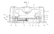
- the ceiling embedded type air conditioner includes a main body frame 10, which takes the form of a substantially square box having an open bottom to accommodate components of the air conditioner therein, a blower fan 12, which may be placed at an interior center position of the main body frame 10 to enable circulation of air, a heat exchanger 11, which has a square annular form and may be placed around the blower fan 12, a drain pan 14, which has a square annular form to correspond to the heat exchanger 11 and may be located under the heat exchanger 11 so as to receive and collect condensed water from the heat exchanger 11, a ceiling panel 16, which defines the bottom of the air conditioner and has a central suction opening 16a for air suction and a peripheral discharge opening for air discharge, a filter 19, which has a disc form and may be located inside the suction opening 16a so as to remove dust or debris from air suctioned through the suction opening 16a, and a filter support member 15, which has a square annular form and may be placed between the ceiling panel 16 and the
- a fan motor 13 to drive the blower fan 12 may be secured to the center of an inner top surface of the main body frame 10.
- the blower fan 12 may be a centrifugal fan that axially suctions air and radially discharges the air. As such, the blower fan 12 acts to suction air through the suction opening 16a of the ceiling panel 16 and discharge the air toward the heat exchanger 11 placed at a radial outer position thereof.
- the drain pan 14 may be located in a lower region of the main body frame 10 and may be configured to receive a lower end of the heat exchanger 11.
- the drain pan 14 has a condensed water receiving groove 14a defined in a bottom surface thereof, a first suction guide passage 14b defined by an inner surface thereof to guide the air having passed through the suction opening 16a into the blower fan 12, and a first discharge guide passage 14c located at the outer side of the condensed water receiving groove 14a to guide the air discharged from the blower fan 12 to the discharge opening 16b.
- a guide duct 14d may be provided in the first suction guide passage 14b so as to guide the air toward the center of the blower fan 12.
- the filter support member 15 has a second suction guide passage 15a and a second discharge guide passage 15b, which are collinearly connected respectively to the first suction guide passage 14b and the first discharge guide passage 14c of the drain pan 14.
- a filter bracket 21 having a circular filter aperture 21 a in which the filter 19 is rotatably inserted may be placed inside the second suction guide passage 15a.
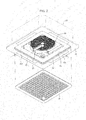
- the ceiling panel 16, as illustrated in FIG. 2 has a square panel form and the above-described suction opening 16a may be a central square opening of the ceiling panel 16.
- the above-described discharge opening 16b includes four discharge openings 16b arranged along the rim of the ceiling panel 16 to correspond to four sides of the ceiling panel 16.
- a suction grill 17 may be fitted into the suction opening 16a of the ceiling panel 16 to cover the suction opening 16a while allowing passage of air.
- Each discharge opening 16b of the ceiling panel 16 may be provided with a guide blade 18 to control the direction of the air discharged through the discharge opening 16b.
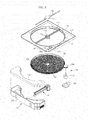
- the ceiling embedded type air conditioner ensures automated cleaning of the filter 19.
- the ceiling embedded type air conditioner as illustrated in FIGS. 3 and 4 , includes filter cleaning devices 22 and 23 to clean the filter 19, and a filter drive mechanism 24 to rotate the filter 19 such that a region to be cleaned by the filter cleaning devices 22 and 23 may vary.
- the filter drive mechanism 24 may be mounted in the filter bracket 21 and includes a filter drive motor 24a to generate rotational power and a gear 24b to be rotated by the filter drive motor 24a.
- the filter 19 may be provided at a distal circumferential edge thereof with teeth 19a.
- the gear 24b may be engaged with the teeth 19a of the filter 19 to transmit rotational power to the teeth 19a so as to enable rotation of the filter 19.
- the filter bracket 21 has a recessed mount 21 i for the filter drive mechanism 24. Additionally, a drive mechanism case 24c may be installed to the filter bracket 21 and assists in fixedly mounting the filter drive mechanism 24 to the filter bracket 21.
- the filter bracket 21 includes a hub 21 b to allow rotatable installation of the filter 19 and a plurality of legs 21 c integrally extending from the hub 21 b so as to be connected to the filter bracket 21.
- the hub 21 b may be positioned at the center of the filter aperture 21 a via the legs 21 c.
- the filter 19 has a central hub aperture 19b to allow the filter 19 to be rotatably installed to the hub 21 b.
- the hub 21 b of the filter bracket 21 may be provided with a positional sensor 25 that will be described hereinafter.
- a hub cover 21 d may be coupled with the hub 21 b.
- a reinforcing bar 21 e may be provided to enhance rigidity of both the hub 21 b and the legs 21 c.
- the filter cleaning devices 22 and 23 include a cleaning unit 22 to remove dust from the filter 19 and a dust storage unit 23 in which dust removed by the cleaning unit 22 may be stored.
- the cleaning unit 22 includes a brush 221, a transfer auger 222, a brush drive motor 223 to rotate the brush 221, an auger drive motor 224 to rotate the transfer auger 222, and a brush cleaner 225.
- the brush 221 extends lengthwise in a radial direction of the filter 19 and serves to sweep dust away from a lower surface of the filter 19 while rotating in contact with the lower surface of the filter 19.
- the transfer auger 222 also extends lengthwise in a radial direction of the filter 19 and may be located under the brush 221 so as to guide the dust removed from the filter 19 by the brush 221 into the dust storage unit 23.
- the brush cleaner 225 to clean the brush 221 may be arranged next to the brush 221 and may be approximately equal or equal in length to the brush 221. As the dust removed from the filter may be adhered to the brush 221, the brush cleaner 225 serves to remove the dust from the brush 221 for cleaning of the brush 221.
- the cleaning unit 22 includes a cleaning unit case 226 in which the brush 221 and the transfer auger 222 are accommodated, the cleaning unit case 226 has an open top to expose the top of the brush 221, a drive case 227 in which the brush drive motor 223 and the auger drive motor 224 are accommodated, and a cleaner guide 228 into which the brush cleaner 225 may be movably inserted, the cleaner guide 228 being coupled to the cleaning unit case 226.
- the brush drive motor 223 and the auger drive motor 224 are respectively secured to a drive bracket 21 h that may be in turn secured to the hub 21 b as described below. That is, the brush drive motor 223 and the auger drive motor 224 are accommodated within the drive case 227 while being secured to the drive bracket 21 h.
- the brush 221 includes a cylindrical base 221 a and a plurality brush files 221 b arranged on the circumference of the base 221 a to come into frictional contact with the filter 19.
- the base 221 a includes a blank portion 221 c in which the brush files 221 b are not arranged. As the brush cleaner 225 removes dust from some of the brush files 221 b, the dust removed from the brush files 221 b may be partially reattached to neighboring ones of the brush files 221 b.
- the blank portion 221 c serves to prevent reattachment of the dust.
- the brush cleaner 225 includes a cleaning zone 225a having a curvature corresponding to the circumference of the brush 221 in which a plurality of cleaner files 225b may be arranged, and a movement guide structure 225c disposed at the rear of the cleaning zone 225a to allow the brush cleaner 225 to be movably inserted into the cleaner guide 228 as described below.
- the above-described brush files 221 b tilt counterclockwise from the brush 221, whereas the cleaner files 225b tilt downward.
- This arrangement may allow cleaning of the filter 19 by the brush 221 and cleaning of the brush 221 by the brush cleaner 225 to be selectively implemented depending on a rotating direction of the brush 221.
- the brush 221 may perform cleaning of the filter 19 when rotated counterclockwise and allow the dust to be removed and fall from the brush files 221 b by the cleaner files 225b of the brush cleaner 225 when rotated clockwise.
- counterclockwise rotation of the brush 221 also causes the brush cleaner 225 to be cleaned as the dust adhered to the brush cleaner 225 may be removed by the brush 221.
- a cam 223b may be fitted onto a rotating shaft 223a of the brush drive motor 223.
- the positional sensor 25 installed to the hub 21 b serves to sense the reference position of the brush 221 via the cam 223b.
- the cam 223b has a radially outwardly protruding position sensing cam portion 223c.
- the positional sensor 25 has a sensing piece 25a to be pressurized and rotated by the position sensing cam portion 223c. As such, if the rotating shaft 223a is rotated to rotate the brush 221, the cam 223b may be rotated along with the brush 221, acting to rotate the sensing piece 25a and allowing the sensor 225 to confirm the reference position of the brush 221.
- the transfer auger 222 has a helical form to guide dust accumulated in the cleaning unit case 226 from one side to the other side via rotation thereof.
- the transfer auger 222 may be a shaftless auger and prevents a lump of fibrous dust from becoming tangled in and accumulated on an auger shaft.
- the cleaning unit case 226 contains a lower auger accommodating region 226a in which the transfer auger 222 may be accommodated and an upper brush accommodating region 226b in which the brush 221 may be accommodated.
- the drive case 227 has a fixed location underneath the hub 21 b, and one end of the cleaning unit case 226 may be secured to the drive bracket 21 h within the drive case 227. Since the other end of the cleaning unit case 226 may be secured to the dust storage unit 23, it will be assumed that the cleaning unit case 226 extends lengthwise in a radial direction of the filter 19 via the drive bracket 21 h and the dust storage unit 23.
- the above-described cam 223b may be accommodated in the drive case 227, and the sensing piece 25a of the above-described positional sensor 25 installed to the hub 21 b penetrates the hub 21 b so as to protrude into the drive case 227.
- the position sensing cam portion 223c of the cam 223b may be sensed by the sensing piece 25a during rotation of the cam 223b.
- the cleaner guide 228 has a movement guide groove 228a into which the brush cleaner 225 may be inserted to be movable toward the brush 221.
- the movement guide structure 225c may be seated in the movement guide groove 228a of the cleaner guide 228 with a plurality of elastic support members 229 interposed therebetween.
- the elastic support members 229 act to elastically push the brush cleaner 225 toward the brush 221.
- the cleaner guide 228 may be located at one side of the cleaning unit case 226 to thereby define a sidewall of the auger accommodating region 226a and the brush accommodating region 226b.
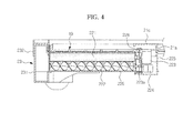
- the dust storage unit 23 includes a dust sump 231 having an open top to store the dust directed by the transfer auger 222 therethrough and a sump cover 232 to cover the open top of the dust sump 231.
- the dust sump 231 has a dust entrance 231 a perforated in a sidewall thereof, to which the above-described cleaning unit case 226 may be connected such that the dust directed thereto by the transfer auger 222 of the cleaning unit 22 is introduced into the dust sump 231 through the dust entrance 231 a.
- a dust discharge port 231 b may be formed in one end of the bottom of the dust sump 231 so that the dust in the dust sump 231 may be removed by a vacuum cleaner.
- An end wall of the dust sump 231 opposite to the dust discharge port 231 b may be provided with an air suction hole 231d so that air may be suctioned into the dust sump 231 while the vacuum cleaner is suctioning the dust from the dust sump 231.
- the dust introduced through the dust entrance 231 a by the transfer auger 222 may be compressed between the transfer auger 222 and an inner surface of the dust sump 231 opposite to the dust entrance 231 a and thereafter, may be moved to opposite ends of the dust sump 231. That is, as a result of compressing the dust via the transfer auger 222, a greater amount of dust may be stored in the dust sump 231.
- An air guide 233 may be installed in the dust sump 231 inside the air suction hole 231d to guide air introduced through the air suction hole 231d to a bottom surface of the dust sump 231, which may assist the vacuum cleaner in efficiently suctioning the dust accumulated on the bottom surface of the dust sump 231.
- the air guide 233 includes a filter portion 233a, which may be located inside the air suction hole 231 d so as to cover the air suction hole 231 d, and an air guide portion 233b, which may be inclined inward and downward from an upper end of the filter portion 233a. As illustrated in FIG.
- the air suctioned through the air suction hole 231 d may be guided downward by the air guide 233 after passing through the filter portion 233a, thereby serving to push the dust accumulated on the bottom surface of the dust sump 231 up, which may assist the vacuum cleaner in efficiently suctioning the dust accumulated in the dust sump 231.
- a dust discharge guide unit 27 may be connected to the dust discharge port 231 b to mediate discharge of dust via the vacuum cleaner.
- the dust discharge guide unit 27, as illustrated in FIGS. 10 and 11 includes a dust discharge guide 271 having a dust discharge hole 271 b, a support bracket 272 attached to the dust sump 231 so as to support the dust discharge guide 271 in a vertically movable manner, and an opening/closing member 273 to open or close the dust discharge hole 271 b according to vertical movement of the dust discharge guide 271.
- the dust discharge guide 271 may be vertically movably connected to the dust discharge port 231 b by use of a plurality of elastic discharge guide members 274 in the form of coil springs.
- the dust discharge guide 271 includes a domed portion 271 a, which may be centrally provided with the dust discharge hole 271 b and has an arc-shaped cross section to easily guide dust to the dust discharge hole 271 b.
- the domed portion 271 a of the dust discharge guide 271 protrudes downward through a through-hole 231 c of the dust discharge port 231 b.
- the dust discharge guide 271 includes a retainer portion 271 c extending outward from the domed portion 271 a so as to be caught by an inner circumferential portion of the dust discharge port 231 b adjacent to the through-hole 231 c, a pair of hinge pin holes 271 d, to which both ends of the above-described opening/closing member are rotatably fitted, and a plurality of first bosses 271e arranged on an upper surface of the retainer portion 271c to support lower ends of the respective elastic discharge guide members 274.
- the support bracket 272 includes an annular support portion 272a to support the dust discharge guide 271 via the elastic discharge guide members 274, and fixing portions 272c extending outward from the support portion 272a so as to be secured to the bottom surface of the dust sump 231.
- the support portion 272a has a center dust discharge aperture 272b, through which dust may be guided to the dust discharge hole 271 b, and a plurality of second bosses 272e may be arranged on a lower surface of the annular support portion 272a to support upper ends of the respective elastic discharge guide members 274. Additionally, rotating guide pieces 272d protrude downward from the lower surface of the support portion 272a to guide rotation of the opening/closing member 273 according to upward movement of the discharge guide 271.
- the opening/closing member 273 includes an opening/closing portion 273a to open or close the dust discharge hole 271 b via rotation thereof, and a pair of hinges 273b extending upward from opposite sides of the opening/closing portion 273a.
- the hinges 273b are respectively provided at upper ends thereof with hinge pins 273c which are rotatably inserted into the hinge pin holes 271 d of the dust discharge guide 271.
- the hinges 273b are further provided with a pair of rotating cam pieces 273d adjacent to the hinge pins 273c.
- the rotating cam pieces 273d interact with the above-described rotating guide pieces 272d as the dust discharge guide 271 may be moved upward, causing rotation of the opening/closing member 273.
- a return spring 275 in the form of a torsion spring may be fitted on each hinge pin 273c.
- the dust discharge guide 271 may be moved upward via deformation of the elastic discharge guide members 274. With movement of the dust discharge guide 271, the rotating cam pieces 273d of the opening/closing member 273 are supported by the rotating guide pieces 272d, which causes the opening/closing member 273 to rotate about the hinge pins 273c.
- the dust discharge hole 271 b closed by the opening/closing portion 273a is opened, whereby dust in the dust sump 231 may be suctioned into the pipe P of the vacuum cleaner through the dust discharge hole 271 b.
- the dust discharge guide 271 may be moved downward by restoration of the elastic discharge guide members 274 and the opening/closing member 273 may be rotated to return to an original position thereof by restoration of the return springs 275, whereby the dust discharge hole 271 is again closed by the opening/closing member 273a.
- the ceiling embedded type air conditioner includes a dust sensor 26 to indicate when the dust sump 231 shall be cleaned.
- the dust sensor 26 may be a photo sensor having a light emitting part 26a and a light receiving part 26b and may be installed to the filter bracket 21.
- a pair of transparent caps 21f and 21g may be arranged at the filter bracket 21 so as to protrude downward from a lower surface of the filter bracket 21.
- the light emitting part 26a and the light receiving part 26b are respectively accommodated in the two transparent caps 21f and 21g.
- the sump cover 232 has sensor holes 232a such that the transparent caps 21f and 21g and the light emitting and receiving parts 26a and 26b accommodated in the caps 21f and 21g protrude into the dust sump 231 through the sump cover 232.
- the dust sump 231 is filled with dust to the extent that the dust fills the space between the two transparent caps 21f and 21 g in which the light emitting part 26a and the light receiving element 26b are accommodated, light from the light emitting part 26a does not reach the light receiving part 26b, which indicates that the dust sump 231 is full of dust.
- the brush 221 may be rotated by the brush drive motor 223 until the sensing piece 25a senses the position sensing cam portion 223c, thereby reaching a reference position thereof.
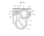
- the filter 19 may be rotated once by approximately 360° or 360°by the filter drive motor 24a and simultaneously, the brush 221 may be rotated by a first angle less than approximately 360° or 360° as illustrated in FIG. 15 so as to clean the filter 19 by the brush files 221 b.
- the brush 221 may be rotated by approximately 150° or 150° counterclockwise in a first direction.
- the brush 221 may be rotated in the first direction by a second angle such that the brush files 221 b used to clean the filter 19 pass through the brush cleaner 225 as illustrated in FIG. 16 .
- the brush 221 is rotated in the first direction by approximately 110° or 110° in consideration of the width of the cleaning zone 225a of the brush cleaner 225, the brush files 221 b used to clean the filter 19 begin to pass through the brush cleaner 225.
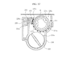
- cleaning of the brush 221 by the brush cleaner 225 and cleaning of the brush cleaner 225 by the brush 221 are alternately implemented. Specifically, when the brush 221 is rotated clockwise in the second direction by a third angle as illustrated in FIG. 17 , the brush files 221 b are cleaned by the brush cleaner 225. When the brush 221 is rotated counterclockwise in the first direction by a fourth angle less than the third angle as illustrated in FIG. 18 , the cleaner files 225b are cleaned by the brush 221.
- the brush 221 may be rotated in the second direction by approximately 60° or 60° to allow the brush files 221 b to be cleaned by the cleaner files 225b and subsequently, may be rotated in the first direction by approximately 30° or 30° to allow the cleaner files 225b to be cleaned by the brush files 221 b.
- the brush files 221 b arranged on the brush 221 are sequentially cleaned whenever rotated by approximately 30° or 30°.
- dust accumulated on a filter may automatically and periodically be removed by a cleaning unit and the removed dust may be stored in a dust storage unit, which eliminates a need to separate and clean the filter.
- the disclosure herein has provided example embodiments of a ceiling embedded type air conditioner having a filter cleaning device to clean a filter, however the disclosure is not so limited to specific embodiments.
- the main body frame of the ceiling embedded type air conditioner has been described as being in the form of a substantially square box, however the ceiling embedded type air conditioner may be in a different form.
- different rotation angles have been disclosed herein regarding rotation of the brush. However, it will be understood by those of ordinary skill in the art that the rotation angles may be adjusted, so long as dust accumulated on the filter may be removed, and dust can be removed from the brush using the brush cleaner.
Landscapes
- Engineering & Computer Science (AREA)
- Chemical & Material Sciences (AREA)
- Combustion & Propulsion (AREA)
- Mechanical Engineering (AREA)
- General Engineering & Computer Science (AREA)
- Air Conditioning Control Device (AREA)
- Air Filters, Heat-Exchange Apparatuses, And Housings Of Air-Conditioning Units (AREA)
- Filtering Of Dispersed Particles In Gases (AREA)
Applications Claiming Priority (1)
| Application Number | Priority Date | Filing Date | Title |
|---|---|---|---|
| KR1020110004582A KR20120083114A (ko) | 2011-01-17 | 2011-01-17 | 천장형 공기조화기 |
Publications (2)
| Publication Number | Publication Date |
|---|---|
| EP2476964A2 true EP2476964A2 (de) | 2012-07-18 |
| EP2476964A3 EP2476964A3 (de) | 2018-04-11 |
Family
ID=45495773
Family Applications (1)
| Application Number | Title | Priority Date | Filing Date |
|---|---|---|---|
| EP12150765.1A Withdrawn EP2476964A3 (de) | 2011-01-17 | 2012-01-11 | In die Decke eingebettete Klimaanlage |
Country Status (4)
| Country | Link |
|---|---|
| US (1) | US8721779B2 (de) |
| EP (1) | EP2476964A3 (de) |
| KR (1) | KR20120083114A (de) |
| CN (1) | CN102589046B (de) |
Cited By (2)
| Publication number | Priority date | Publication date | Assignee | Title |
|---|---|---|---|---|
| CN116085994A (zh) * | 2022-12-26 | 2023-05-09 | 珠海格力电器股份有限公司 | 一种清洗组件、空调器及空调器清洗方法 |
| CN117258454A (zh) * | 2023-10-13 | 2023-12-22 | 新泰市建筑安装工程有限公司 | 一种建筑工程施工用的降尘设备 |
Families Citing this family (30)
| Publication number | Priority date | Publication date | Assignee | Title |
|---|---|---|---|---|
| JP5338322B2 (ja) * | 2008-01-11 | 2013-11-13 | ダイキン工業株式会社 | 空気調和装置の室内ユニット |
| JP5606805B2 (ja) * | 2010-06-08 | 2014-10-15 | 三洋電機株式会社 | エアフィルタ掃除装置、及び投写型映像表示装置 |
| CN103673106A (zh) * | 2013-12-13 | 2014-03-26 | 宁波瑞易电器科技发展有限公司 | 新型智能空调 |
| CN203874594U (zh) * | 2014-06-12 | 2014-10-15 | 百朗楼宇电气用品(惠州)有限公司 | 一种直接悬挂于墙壁上的空气净化器 |
| CN204034442U (zh) * | 2014-08-15 | 2014-12-24 | 百朗楼宇电气用品(惠州)有限公司 | 一种管道式空气净化器 |
| CN204034441U (zh) * | 2014-08-15 | 2014-12-24 | 百朗楼宇电气用品(惠州)有限公司 | 一种管道式空气净化器 |
| TR201617263T1 (tr) * | 2015-03-27 | 2017-08-21 | Mitsubishi Electric Corp | Klima cihazı iç ünitesi. |
| JP6289739B2 (ja) * | 2015-03-27 | 2018-03-07 | 三菱電機株式会社 | 空気調和機の室内機 |
| KR101707617B1 (ko) | 2015-09-30 | 2017-02-21 | 삼성전자주식회사 | 공기 조화기 및 그 제어 방법 |
| JP6330775B2 (ja) * | 2015-09-30 | 2018-05-30 | ダイキン工業株式会社 | 空調室内機 |
| KR102531643B1 (ko) | 2016-01-15 | 2023-05-11 | 삼성전자주식회사 | 공기조화기 |
| KR101926104B1 (ko) * | 2016-05-09 | 2018-12-06 | 엘지전자 주식회사 | 천장형 공기 조화기 |
| JP6768072B2 (ja) * | 2016-09-12 | 2020-10-14 | シャープ株式会社 | 空気清浄機 |
| EP3336444B1 (de) * | 2016-11-07 | 2019-09-11 | Mitsubishi Electric Corporation | Deckenverborgene klimaanlage |
| KR101828587B1 (ko) * | 2017-06-26 | 2018-02-13 | (주)센도리 | 먼지제거기능을 구비한 공조장치 |
| CN107461905B (zh) * | 2017-07-25 | 2021-01-05 | 青岛海尔空调电子有限公司 | 用于空调器的箱盖安装结构 |
| KR102438130B1 (ko) * | 2017-08-28 | 2022-08-31 | 삼성전자주식회사 | 공기청정기 |
| KR102574664B1 (ko) * | 2017-09-29 | 2023-09-05 | 코웨이 주식회사 | 공기청정기 |
| CN107990432B (zh) * | 2017-11-24 | 2021-01-22 | 芜湖美智空调设备有限公司 | 除尘传感器和窗机 |
| KR101946255B1 (ko) * | 2018-01-11 | 2019-02-11 | (주)센도리 | 먼지 제거가 가능한 필터 구조 |
| US10655645B2 (en) * | 2018-03-28 | 2020-05-19 | Lenovo Enterprise Solutions (Singapore) Pte. Ltd. | Fan systems including brushes and bristles for self-cleaning |
| EP3851755B1 (de) * | 2018-09-30 | 2022-09-21 | GD Midea Air-Conditioning Equipment Co., Ltd. | Steuerungsverfahren für klimaanlageninnenraumeinheit |
| KR102033420B1 (ko) * | 2019-02-27 | 2019-10-17 | 김완중 | 환기구 장치 |
| KR102002157B1 (ko) * | 2019-04-12 | 2019-07-19 | (주)상지엔지니어링건축사사무소 | 공동주택 세대 현관의 안전 바닥 패널 |
| KR102237785B1 (ko) * | 2019-10-16 | 2021-04-07 | 신홍섭 | 음식물 쓰레기 처리 장치 |
| CN111644305B (zh) * | 2020-06-29 | 2021-06-11 | 蔡欧 | 一种环保型喷漆房 |
| CN112413757A (zh) * | 2020-11-24 | 2021-02-26 | 温州声约贸易有限公司 | 一种针对中央空调关闭后的智能化清扫及除菌装置 |
| JP7691327B2 (ja) * | 2021-09-22 | 2025-06-11 | シャープ株式会社 | フィルタ清掃装置、及び空気調和機 |
| KR20230099396A (ko) | 2021-12-27 | 2023-07-04 | 코웨이 주식회사 | 공기 청정기 |
| CN221015013U (zh) * | 2023-02-28 | 2024-05-28 | 满洲里达赉湖热电有限公司 | 一种清理机构及烟气废热利用装置 |
Citations (1)
| Publication number | Priority date | Publication date | Assignee | Title |
|---|---|---|---|---|
| EP2249094A1 (de) * | 2007-12-19 | 2010-11-10 | Daikin Industries, Ltd. | Einheit zur reinigung einer luftklimatisierungsvorrichtung |
Family Cites Families (26)
| Publication number | Priority date | Publication date | Assignee | Title |
|---|---|---|---|---|
| US6514303B2 (en) * | 2001-01-09 | 2003-02-04 | Case Corporation | Rotary air screen for a work machine |
| JP4110375B2 (ja) * | 2002-06-27 | 2008-07-02 | 株式会社富士通ゼネラル | 空気調和機 |
| KR20060050921A (ko) * | 2004-09-02 | 2006-05-19 | 가부시키가이샤 후지츠 제네랄 | 공기조화기 |
| US8021469B2 (en) * | 2005-07-14 | 2011-09-20 | Access Business Group International Llc | Control methods for an air treatment system |
| US20070022720A1 (en) * | 2005-07-27 | 2007-02-01 | The Toro Company | Cleaner for cooling system screen of outdoor power equipment unit |
| US8404034B2 (en) * | 2005-12-10 | 2013-03-26 | Lg Electronics Inc. | Vacuum cleaner and method of controlling the same |
| US20100155584A1 (en) * | 2006-09-13 | 2010-06-24 | Bernd Mack | Sensor for detecting dirt and/or rain and method for operating a sensor |
| CN101606028B (zh) * | 2007-02-09 | 2011-04-13 | 大金工业株式会社 | 空调装置的室内机组 |
| KR100858500B1 (ko) | 2007-04-06 | 2008-09-16 | 엘지전자 주식회사 | 공기조화기 |
| CN101290151B (zh) * | 2007-04-18 | 2010-05-26 | 海尔集团公司 | 空调过滤网自清洁装置 |
| BRPI0810273A2 (pt) * | 2007-05-17 | 2019-09-24 | Daikin Ind Ltd | "unidade interna de um condicionador de ar". |
| CN201098592Y (zh) * | 2007-09-25 | 2008-08-13 | 潘志伟 | 自报警空气净化器 |
| JP4325722B2 (ja) * | 2007-12-17 | 2009-09-02 | ダイキン工業株式会社 | 空気調和装置の室内ユニット |
| JP4433056B2 (ja) * | 2008-01-09 | 2010-03-17 | ダイキン工業株式会社 | 空気調和装置の室内ユニット |
| JP4618302B2 (ja) * | 2008-01-17 | 2011-01-26 | 株式会社富士通ゼネラル | 空気調和機 |
| KR101329754B1 (ko) * | 2008-01-24 | 2013-11-14 | 엘지전자 주식회사 | 천장형 공기조화기 |
| KR101197879B1 (ko) * | 2008-01-25 | 2012-11-05 | 다이킨 고교 가부시키가이샤 | 공조기의 실내 유닛 |
| KR101340528B1 (ko) * | 2008-02-04 | 2013-12-11 | 엘지전자 주식회사 | 천장형 공기조화기 |
| US8097050B2 (en) * | 2008-02-26 | 2012-01-17 | Cnh America Llc | Rotary vacuum apparatus for air screen |
| JP4772096B2 (ja) * | 2008-06-30 | 2011-09-14 | 三菱電機株式会社 | 天井埋込型空気調和機 |
| JP2010043781A (ja) * | 2008-08-12 | 2010-02-25 | Sanyo Electric Co Ltd | 空気調和機 |
| JP5193782B2 (ja) * | 2008-09-30 | 2013-05-08 | 三洋電機株式会社 | 空気調和機、及び、空気調和機の制御方法 |
| US7798078B2 (en) * | 2008-11-14 | 2010-09-21 | Cnh Canada, Ltd. | Granular containment assembly and method |
| JP2010216707A (ja) | 2009-03-16 | 2010-09-30 | Toshiba Carrier Corp | 天井埋込み形空気調和機のフィルタ装置 |
| US8647404B2 (en) * | 2009-04-30 | 2014-02-11 | Daikin Industries, Ltd. | Indoor unit of air conditioner |
| JP2012128280A (ja) * | 2010-12-16 | 2012-07-05 | Sanyo Electric Co Ltd | エアフィルタ装置及び電子機器 |
-
2011
- 2011-01-17 KR KR1020110004582A patent/KR20120083114A/ko not_active Ceased
-
2012
- 2012-01-10 US US13/347,217 patent/US8721779B2/en active Active
- 2012-01-11 EP EP12150765.1A patent/EP2476964A3/de not_active Withdrawn
- 2012-01-12 CN CN201210008773.5A patent/CN102589046B/zh not_active Expired - Fee Related
Patent Citations (1)
| Publication number | Priority date | Publication date | Assignee | Title |
|---|---|---|---|---|
| EP2249094A1 (de) * | 2007-12-19 | 2010-11-10 | Daikin Industries, Ltd. | Einheit zur reinigung einer luftklimatisierungsvorrichtung |
Cited By (3)
| Publication number | Priority date | Publication date | Assignee | Title |
|---|---|---|---|---|
| CN116085994A (zh) * | 2022-12-26 | 2023-05-09 | 珠海格力电器股份有限公司 | 一种清洗组件、空调器及空调器清洗方法 |
| CN117258454A (zh) * | 2023-10-13 | 2023-12-22 | 新泰市建筑安装工程有限公司 | 一种建筑工程施工用的降尘设备 |
| CN117258454B (zh) * | 2023-10-13 | 2024-02-09 | 新泰市建筑安装工程有限公司 | 一种建筑工程施工用的降尘设备 |
Also Published As
| Publication number | Publication date |
|---|---|
| US20120180665A1 (en) | 2012-07-19 |
| US8721779B2 (en) | 2014-05-13 |
| CN102589046A (zh) | 2012-07-18 |
| EP2476964A3 (de) | 2018-04-11 |
| KR20120083114A (ko) | 2012-07-25 |
| CN102589046B (zh) | 2016-12-07 |
Similar Documents
| Publication | Publication Date | Title |
|---|---|---|
| EP2476964A2 (de) | In die Decke eingebettete Klimaanlage | |
| CN104949214B (zh) | 除湿机 | |
| EP2050380B1 (de) | Reinigungsroboter | |
| CN104949215B (zh) | 除湿机 | |
| JP5276166B2 (ja) | 空気調和機 | |
| JP5108119B2 (ja) | ダストボックス、フィルタ清掃装置および空気調和機 | |
| EP3178361B1 (de) | Roboterreiniger | |
| JP5108121B2 (ja) | フィルタ保持装置、フィルタ清掃装置および空気調和機 | |
| CN107461807B (zh) | 空调器的除尘装置及具有其的空调器 | |
| KR101633789B1 (ko) | 공기조화기 | |
| CN103250006A (zh) | 过滤器保持装置、过滤器清扫装置和空气调节机 | |
| JP2010223453A (ja) | 空気調和機 | |
| JP2008170034A (ja) | レンジフード | |
| KR20130055369A (ko) | 가습 제습 복합기의 토출구 구조 | |
| KR20090095982A (ko) | 공기 조화기 | |
| KR20130055370A (ko) | 가습 제습 복합기의 제습수 수용 구조 | |
| EP3124683A1 (de) | Wäschetrockner | |
| KR20060136165A (ko) | 보조 리프터를 갖는 드럼세탁기 | |
| KR20130055374A (ko) | 가습 제습 복합기의 댐퍼 프레임 구조 | |
| KR20100070021A (ko) | 건조기 및 건조기의 제어 방법 | |
| CN119523350A (zh) | 清洁装置 | |
| KR20130055381A (ko) | 가습 제습 복합기의 리모컨 보관 구조 | |
| KR20130055371A (ko) | 가습 제습 복합기의 먼지센서 취부 구조 | |
| KR20130055299A (ko) | 가습 제습 복합기의 흡입구 구조 | |
| KR20130055301A (ko) | 가습 제습 복합기의 제습수 안내 구조 |
Legal Events
| Date | Code | Title | Description |
|---|---|---|---|
| PUAI | Public reference made under article 153(3) epc to a published international application that has entered the european phase |
Free format text: ORIGINAL CODE: 0009012 |
|
| AK | Designated contracting states |
Kind code of ref document: A2 Designated state(s): AL AT BE BG CH CY CZ DE DK EE ES FI FR GB GR HR HU IE IS IT LI LT LU LV MC MK MT NL NO PL PT RO RS SE SI SK SM TR |
|
| AX | Request for extension of the european patent |
Extension state: BA ME |
|
| RAP1 | Party data changed (applicant data changed or rights of an application transferred) |
Owner name: SAMSUNG ELECTRONICS CO., LTD. |
|
| 17P | Request for examination filed |
Effective date: 20160713 |
|
| RBV | Designated contracting states (corrected) |
Designated state(s): AL AT BE BG CH CY CZ DE DK EE ES FI FR GB GR HR HU IE IS IT LI LT LU LV MC MK MT NL NO PL PT RO RS SE SI SK SM TR |
|
| PUAL | Search report despatched |
Free format text: ORIGINAL CODE: 0009013 |
|
| AK | Designated contracting states |
Kind code of ref document: A3 Designated state(s): AL AT BE BG CH CY CZ DE DK EE ES FI FR GB GR HR HU IE IS IT LI LT LU LV MC MK MT NL NO PL PT RO RS SE SI SK SM TR |
|
| AX | Request for extension of the european patent |
Extension state: BA ME |
|
| RIC1 | Information provided on ipc code assigned before grant |
Ipc: F24F 1/00 20110101AFI20180303BHEP Ipc: F24F 13/06 20060101ALI20180303BHEP Ipc: F24F 3/16 20060101ALI20180303BHEP |
|
| STAA | Information on the status of an ep patent application or granted ep patent |
Free format text: STATUS: EXAMINATION IS IN PROGRESS |
|
| 17Q | First examination report despatched |
Effective date: 20190926 |
|
| GRAP | Despatch of communication of intention to grant a patent |
Free format text: ORIGINAL CODE: EPIDOSNIGR1 |
|
| STAA | Information on the status of an ep patent application or granted ep patent |
Free format text: STATUS: GRANT OF PATENT IS INTENDED |
|
| INTG | Intention to grant announced |
Effective date: 20201123 |
|
| STAA | Information on the status of an ep patent application or granted ep patent |
Free format text: STATUS: THE APPLICATION IS DEEMED TO BE WITHDRAWN |
|
| 18D | Application deemed to be withdrawn |
Effective date: 20210407 |