EP2476995A1 - Appareil et procédé de mesure de déplacement, procédé de fabrication de moule pour mouler un élément optique et élément optique - Google Patents
Appareil et procédé de mesure de déplacement, procédé de fabrication de moule pour mouler un élément optique et élément optique Download PDFInfo
- Publication number
- EP2476995A1 EP2476995A1 EP20110195495 EP11195495A EP2476995A1 EP 2476995 A1 EP2476995 A1 EP 2476995A1 EP 20110195495 EP20110195495 EP 20110195495 EP 11195495 A EP11195495 A EP 11195495A EP 2476995 A1 EP2476995 A1 EP 2476995A1
- Authority
- EP
- European Patent Office
- Prior art keywords
- laser beam
- photodetector
- light quantity
- output
- laser
- Prior art date
- Legal status (The legal status is an assumption and is not a legal conclusion. Google has not performed a legal analysis and makes no representation as to the accuracy of the status listed.)
- Withdrawn
Links
- 238000006073 displacement reaction Methods 0.000 title claims abstract description 44
- 230000003287 optical effect Effects 0.000 title claims description 54
- 238000000034 method Methods 0.000 title claims description 48
- 238000004519 manufacturing process Methods 0.000 title claims description 6
- 238000000465 moulding Methods 0.000 title claims description 6
- 238000005520 cutting process Methods 0.000 claims description 34
- 238000005259 measurement Methods 0.000 description 34
- 238000009826 distribution Methods 0.000 description 18
- 230000008569 process Effects 0.000 description 16
- 238000013461 design Methods 0.000 description 11
- 238000010586 diagram Methods 0.000 description 11
- 238000012545 processing Methods 0.000 description 11
- 230000009467 reduction Effects 0.000 description 5
- 230000008859 change Effects 0.000 description 4
- 230000000694 effects Effects 0.000 description 4
- 229910003460 diamond Inorganic materials 0.000 description 3
- 239000010432 diamond Substances 0.000 description 3
- 238000010606 normalization Methods 0.000 description 3
- 239000011521 glass Substances 0.000 description 1
- 238000009434 installation Methods 0.000 description 1
- 238000003754 machining Methods 0.000 description 1
- 238000012986 modification Methods 0.000 description 1
- 230000004048 modification Effects 0.000 description 1
- 230000035945 sensitivity Effects 0.000 description 1
- 238000007493 shaping process Methods 0.000 description 1
Images


Classifications
-
- G—PHYSICS
- G01—MEASURING; TESTING
- G01B—MEASURING LENGTH, THICKNESS OR SIMILAR LINEAR DIMENSIONS; MEASURING ANGLES; MEASURING AREAS; MEASURING IRREGULARITIES OF SURFACES OR CONTOURS
- G01B11/00—Measuring arrangements characterised by the use of optical techniques
- G01B11/002—Measuring arrangements characterised by the use of optical techniques for measuring two or more coordinates
-
- B—PERFORMING OPERATIONS; TRANSPORTING
- B29—WORKING OF PLASTICS; WORKING OF SUBSTANCES IN A PLASTIC STATE IN GENERAL
- B29C—SHAPING OR JOINING OF PLASTICS; SHAPING OF MATERIAL IN A PLASTIC STATE, NOT OTHERWISE PROVIDED FOR; AFTER-TREATMENT OF THE SHAPED PRODUCTS, e.g. REPAIRING
- B29C33/00—Moulds or cores; Details thereof or accessories therefor
- B29C33/38—Moulds or cores; Details thereof or accessories therefor characterised by the material or the manufacturing process
- B29C33/3842—Manufacturing moulds, e.g. shaping the mould surface by machining
Definitions
- Embodiments of the present invention relates to an apparatus and method for measuring displacement of an object to be measured (hereinafter, simply referred to as an "object") in a contactless manner, and in particular, relates to measurement of displacement of an object with a laser beam.
- Processing with, for example, a working machine has required information regarding the position of a tool on the working machine and the shape of the tip of the tool.
- a workpiece has been subjected to dummy processing and has then been detached from the working machine.
- Tool marks in the dummy processing have been determined with a measuring device other than the working machine, thus determining the position of the tool on the working machine and the shape of the tip thereof.
- a tool is allowed to block a laser beam and a change in quantity of blocked light is determined, such that displacement of the tool relative to a laser beam source is measured on a working machine in a contactless manner (refer to Japanese Patent Laid-Open No. 62-88555 and No. 2005-308605 ).
- the related-art displacement measuring apparatuses and methods for determining a change in quantity of blocked light have such disadvantages that the stability of light quantity (hereinafter, referred to as “light quantity stability”) of a laser beam, light quantity distribution thereof, and deflection of the optical axis (hereinafter, referred to as “optical axis deflection”) thereof may cause a measurement error.
- light quantity stability the stability of light quantity of a laser beam
- optical axis deflection deflection of the optical axis
- One disclosed aspect of the embodiments has been made in consideration of the above-described circumstances.
- One disclosed aspect of the embodiments provides a displacement measuring apparatus and method capable of reducing measurement errors based on the light quantity stability of a laser beam, light quantity distribution thereof, and optical axis deflection thereof, a method of making a die for molding an optical element, and an optical element.
- the present invention in its first aspect provides a displacement measuring apparatus as specified in claims 1 to 6.
- the present invention in its second aspect provides a displacement measuring method as specified in claims 7 to 12.
- the present invention in its third aspect provides a method of making a die for molding an optical element as specified in claim 13.
- the present invention in its fourth aspect provides an optical element as specified in claim 14.
- displacement of the object relative to the laser light source is calculated on the basis of the difference between outputs of a first photodetector and a second photodetector which have received first and second laser beams, respectively, thus reducing measurement errors based on the light quantity stability, light quantity distribution, and optical axis deflection of the laser beam emitted from the laser light source.
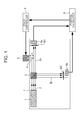
- Fig. 1 is a diagram illustrating a configuration of a displacement measuring apparatus according to a first embodiment.
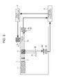
- Fig. 2 is a diagram illustrating a configuration of a displacement measuring apparatus according to a second embodiment.
- Fig. 3 is a diagram illustrating a configuration of a displacement measuring apparatus according to a third embodiment.
- Fig. 4 is a diagram illustrating a displacement measuring apparatus according to a fourth embodiment.
- Fig. 5 is a perspective view of a cutter, serving as an object to be measured by the displacement measuring apparatus according to any of the embodiments.
- Fig. 6 is a flow diagram illustrating a process to measure the displacement of an object according to one aspect of the embodiments.
- One disclosed feature of the embodiments may be described as a process which is usually depicted as a flowchart, a flow diagram, a timing diagram, a structure diagram, or a block diagram.
- a flowchart or a timing diagram may describe the operations or events as a sequential process, the operations may be performed, or the events may occur, in parallel or concurrently.
- An operation in a flowchart may be optional.
- the order of the operations or events may be re-arranged.
- a process is terminated when its operations are completed.
- a process may correspond to a method, a program, a procedure, a method of manufacturing or fabrication, a sequence of operations performed by an apparatus, a machine, or a logic circuit, etc.
- Fig. 1 illustrates a configuration of a displacement measuring apparatus according to a first embodiment.
- a laser beam source 1 emits a laser beam 2 having a diameter of 3 mm.
- a beam splitter 3 splits the laser beam 2 into two laser beams 2a and 2b.
- a drive stage 5 is used to fix an object 4, such as a tool. This drive stage 5 may be moved in a direction in which the object 4 blocks the laser beam (hereinafter, referred to as a "first laser beam") 2a, one of the two laser beams.
- a first photodetector 6a is disposed downstream of the object 4 in a direction in which the laser beam is emitted.
- the first laser beam 2a leaving the beam splitter 3 is partially blocked by the object 4 and then impinges on the first photodetector 6a.
- the first photodetector 6a measures the light quantity of the incident first laser beam 2a.
- a second photodetector 6b receives the laser beam (hereinafter, referred to as a "second laser beam") 2b, which is one of the two laser beams and travels in a direction different from the traveling direction of the first laser beam 2a, and measures the light quantity of the second laser beam 2b.
- the second photodetector 6b is disposed such that the second laser beam 2b received by the second photodetector 6b and the first laser beam 2a unblocked at the position of the object 4 correspond to the same part of the laser beam 2 before being split.
- the laser beam source 1, the beam splitter 3, and the first and second photodetectors 6a and 6b are secured to a base 7.
- a position calculator 8 functions as a calculating unit configured to calculate the position of the object 4 on the basis of outputs of the first and second photodetectors 6a and 6b.
- a stage controller 9 controls a driving unit (not illustrated) for moving the drive stage 5 in the direction, indicated by an arrow A, in which the first laser beam 2a is blocked. The stage controller 9 controls the amount of driving by the driving unit (not illustrated) on the basis of an output from the position calculator 8.
- displacement of the object 4 is measured by measurement of a change in output at a position where the object 4 has blocked a certain quantity (e.g., approximately 50%) of the first laser beam 2a, or the position of the object 4 relative to the first laser beam 2a.
- a certain quantity e.g., approximately 50%
- Determination of a position where the object 4 has blocked approximately 50% of the first laser beam 2a will be described below.
- the reason for such determination is that since the laser beam 2 has Gaussian distribution, the highest sensitivity is obtained at the position where the object 4 has blocked approximately 50% of the first laser beam 2a.
- the second photodetector 6b is also positioned such that approximately 50% of the second laser beam 2b passes outside the photodetector.
- the installation position of the second photodetector 6b is a position where a width W1 of the first laser beam 2a, blocked by the object 4, incident on the first photodetector 6a is equal to a width W2 of the second laser beam 2b incident on the second photodetector 6b.
- the second photodetector 6b is positioned such that the light quantity of part of the second laser beam 2b incident on the second photodetector 6b is equal to that of part of the first laser beam 2a incident on the first photodetector 6a.
- Vb (%) that represents the quantity of light received by the second photodetector 6b is expressed by the following equation. Since the measurement error coefficient D is an error based on angular deflection of the laser beam 2 emitted from the laser light source 1, the product of the coefficient D and the distance Lb1 affects the light quantity output Vb (%).
- the distance Lb1 is known because it is a design value.
- Vb % C ⁇ 50 ⁇ D ⁇ Lb ⁇ 1
- the light quantity output Vb (%) of the second photodetector 6b is affected by the light quantity stability, light quantity distribution, and optical axis deflection of the laser beam 2. Accordingly, measuring the light quantity output Vb (%) of the second photodetector 6b enables measurement of the light quantity stability, light quantity distribution, and optical axis deflection of the laser beam 2 emitted from the laser beam source 1.
- Va (%) that represents the quantity of light received by the first photodetector 6a is expressed by the following equation.
- the distance La1 is known because it is a design value.
- Va % C ⁇ X ⁇ D ⁇ La ⁇ 1
- a value Vb is equal to a value Va. If the light quantity stability and light quantity distribution of the laser beam 2 are poor and the optical axis thereof is deflected, the value Vb will differ from the value Va. In the case where the value Vb differs from the value Va, the drive stage 5 is moved such that the value Va is equal to the value Vb.
- the above-described movement of the drive stage 5 such that the value Va is equal to the value Vb allows determination of the position where the object 4 blocks approximately 50% of the first laser beam 2a.
- the measurement error coefficient C based on the light quantity stability is high, normalization may be performed and the drive stage 5 may be moved such that Va/Vb is 1.
- subtraction may be performed and the drive stage 5 may be moved such that (Va-Vb) is 0.
- the laser beam 2 is split into two laser beams and the second laser beam 2b, serving one of the two laser beams, is received by the second photodetector 6b.
- the position where the object 4 has blocked the first laser beam 2a is determined on the basis of the light quantity output Vb (%) of the second photodetector 6b.
- the position where the object 4 has blocked the first laser beam 2a may be determined after reduction of the effects of the light quantity, light quantity distribution, and optical axis deflection of the laser beam 2.
- the determination of the position where the object 4 has blocked the first laser beam 2a after reduction of the effects of the light quantity of the laser beam 2 and the like allows accurate measurement of displacement of the object 4.
- the stage controller 9 controls the amount of driving by the driving unit on the basis of the determined position, so that the object 4 may be moved to an intended position, for example, the position where the object 4 blocks approximately 50% of the first laser beam 2a.
- the object 4 is moved such that the light quantity of the first laser beam 2a associated with a target position of the object 4 is equal to that of the second laser beam 2b, so that the object 4 may be moved to the intended position.
- displacement of the object 4 relative to the laser light source 1 is calculated on the basis of the difference between outputs of the first and second photodetectors 6a and 6b which have received the first and second laser beams, so that measurement errors based on the light quantity stability, light quantity distribution, and optical axis deflection of the laser beam 2 may be reduced.
- FIG. 2 illustrates a configuration of a displacement measuring apparatus according to the present embodiment.
- the same reference numerals as those in Fig. 1 denote the same or equivalent components.
- a knife edge 10, serving as an obstruction that blocks the second laser beam 2b, is disposed between the beam splitter 3 and the second photodetector 6b.
- the knife edge 10 is disposed such that only part of the second laser beam 2b impinges on the second photodetector 6b, the part having the same optical axis as that of unblocked part of the first laser beam 2a at the position of the object 4 before the laser beam 2 is split.
- the laser light source 1, the beam splitter 3, the first and second photodetectors 6a and 6b, and the knife edge 10 are secured to the base 7.
- displacement is measured in a manner similar to the foregoing first embodiment, namely, by measurement of a position where the object 4 has blocked a certain quantity of the first laser beam 2a, or a position of the object 4 relative to the first laser beam 2a.
- the light quantity output Vb (%) of the second photodetector 6b is affected by the light quantity stability, light quantity distribution, and optical axis deflection of the laser beam 2. Accordingly, measuring the light quantity output Vb (%) of the second photodetector 6b enables measurement of the light quantity stability, light quantity distribution, and optical axis deflection of the laser beam 2.
- the drive stage 5 may be moved such that the light quantity output Va (%) of the first photodetector 6a is equal to the light quantity output Vb (%) of the second photodetector 6b.
- the measurement error coefficient C based on the light quantity stability is high, normalization may be performed and the drive stage 5 may be moved such that Va/Vb is 1.
- subtraction may be performed and the drive stage 5 may be moved such that (Va-Vb) is 0.
- the second laser beam 2b passed by the knife edge 10 is received by the second photodetector 6b and a position where the object 4 has blocked the first laser beam 2a is determined on the basis of the light quantity output Vb (%) of the second photodetector 6b. Consequently, the position where the object 4 has blocked the first laser beam 2a may be determined after reduction of the effects of the light quantity, light quantity distribution, and optical axis deflection of the laser beam 2. Furthermore, since the knife edge 10 is used, the second laser beam 2b may be blocked with a simple configuration such that the second laser beam 2b blocked by the knife edge 10 and the first laser beam 2a blocked by the object 4 correspond to the same part of the laser beam 2 before being split.
- FIG. 3 illustrates a configuration of a displacement measuring apparatus according to the present embodiment.
- the same reference numerals as those in Fig. 2 denote the same or equivalent components.
- condenser lenses 11a to 11d having the same focal length are arranged on optical paths of the first and second laser beams 2a and 2b and constitute a condenser optical system.
- the drive stage 5 may be moved in the direction, indicated by the arrow A, in which the object 4 blocks the first laser beam 2a and in a direction, indicated by an arrow B, along the optical axis of the first laser beam 2a.
- the knife edge 10 is secured at the focal point of the condenser lens 11c in the direction along the optical axis of the second laser beam 2b.
- the laser light source 1, the beam splitter 3, the first and second photodetectors 6a and 6b, the knife edge 10, and the condenser lenses 11a to 11d are secured to the base 7.
- the drive stage 5 is driven to move the object 4 to the focal point of the condenser lens 11a in the direction along the optical axis of the first laser beam 2a. Whether the object 4 has reached the focal point of the condenser lens 11a is determined on the basis of the light quantity output Va (%) of the first photodetector 6a.
- the highest light quantity output Va (%) is obtained at the focal point during movement of the object 4 in the direction along the optical axis of the first laser beam 2a. Accordingly, moving the object 4 to the position where the highest light quantity output Va (%) is obtained allows movement of the object 4 to the focal point of the condenser lens 11a.
- the light quantity output Vb (%) of the second photodetector 6b is measured, thus determining a position where the object 4 has blocked the first laser beam 2a.
- C denotes the measurement error coefficient based on the light quantity stability
- D denotes the measurement error coefficient based on the optical axis deflection
- Lb2 denotes the distance between the laser light source 1 and the knife edge 10
- Vb % C ⁇ 50 ⁇ D ⁇ Lb ⁇ 2
- the light quantity output Vb (%) of the second photodetector 6b is affected by the light quantity stability, light quantity distribution, and optical axis deflection of the laser beam 2. Accordingly, measuring the light quantity output Vb (%) of the second photodetector 6b enables measurement of the light quantity stability, light quantity distribution, and optical axis deflection of the laser beam 2.
- the light quantity output Va (%) of the first photodetector 6a is expressed by the following equation.
- the distance La2 is known because it is a design value.
- Va % C ⁇ X ⁇ D ⁇ La ⁇ 2
- the drive stage 5 is moved such that the light quantity output Va (%) of the first photodetector 6a is equal to the light quantity output Vb (%) of the second photodetector 6b.
- the second laser beam 2b is received by the second photodetector 6b and a position where the object 4 has blocked the first laser beam 2a is determined on the basis of the light quantity output Vb (%) of the second photodetector 6b. Consequently, the position where the object 4 has blocked the first laser beam 2a may be determined after reduction of the effects of the light quantity, light quantity distribution, and optical axis deflection of the laser beam 2. Furthermore, since the first laser beam 2a is focused on the position of the object 4 and the second laser beam 2b is focused on the position of the knife edge 10, the position where the object 4 has blocked the first laser beam 2a may be determined with higher accuracy.
- FIG. 4 illustrates a configuration of a displacement measuring apparatus according to the present embodiment.
- the same reference numerals as those in Fig. 3 denote the same or equivalent components.
- a first beam splitter 3a splits the laser beam 2 into the first laser beam 2a whose light quantity is 33% of that of the laser beam 2 and the second laser beam 2b whose light quantity is 66% of that of the laser beam 2.
- a second beam splitter 3b splits the second laser beam 2b into two laser beams 2c and 2d. In the present embodiment, a half mirror is used as the second beam splitter 3b.
- the first laser beam 2a is partially blocked by the object 4.
- the first photodetector 6a measures the light quantity of the partially blocked first laser beam 2a.
- the second photodetector 6b measures the light quantity of the laser beam (hereinafter, referred to as a "third laser beam") 2c, one of the two laser beams leaving the second beam splitter 3b.
- the knife edge 10 is disposed such that the third laser beam 2c received by the second photodetector 6b and the first laser beam 2a unblocked at the position of the object 4 correspond to the same part of the laser beam 2 before being split.
- the knife edge 10 is secured at the focal point of the condenser lens 11c in the direction along the optical axis of the third laser beam 2c, namely, the position where approximately 50% of the third laser beam 2c is unblocked.
- the laser beam (hereinafter, referred to as a "fourth laser beam”) 2d the other of the two laser beams leaving the second beam splitter 3b, the light quantity is measured by a third photodetector 6c.
- the laser light source 1, the first and second beam splitters 3a and 3b, the first to third photodetectors 6a to 6c, the knife edge 10, and the condenser lenses 11a to 11d are secured to the base 7.
- the position of the object 4 is calculated on the basis of outputs of the first to third photodetectors 6a to 6c.
- a method of measuring displacement according to the present embodiment and a method of driving the drive stage 5 will now be described.
- the drive stage 5 is driven to move the object 4 to the focal point of the condenser lens 11a, as indicated by the arrow B, in the direction along the optical axis of the first laser beam 2a.
- the focal point of the condenser lens 11a is determined on the basis of the light quantity output Va of the first photodetector 6a. For example, in the case where the quantity of light blocked by the object 4 is less than approximately 50%, the highest light quantity output Va is obtained at the focal point during movement of the object 4 in the direction along the optical axis of the first laser beam 2a.
- the light quantity output Vb (%) of the second photodetector 6b is expressed by the following equation. Since the measurement error coefficient D is an error based on angular deflection of the laser beam 2 emitted from the laser light source 1, the product of the coefficient D and the distance Lb2 affects the light quantity output Vb (%).
- the distance Lb2 is known because it is a design value.
- Vb % C ⁇ 50 ⁇ D ⁇ Lb ⁇ 2
- the light quantity output Va (%) of the first photodetector 6a is expressed by the following equation.
- the distance La2 is known because it is a design value.
- Va % C ⁇ X ⁇ D ⁇ La ⁇ 2
- Vc (%) of the photodetector 6c is expressed by the following equation.
- Vc % C ⁇ 33
- the position where the object 4 has blocked approximately 50% of the first laser beam 2a is determined. Accordingly, the drive stage 5 is moved such that the light quantity output Va of the first photodetector 6a is equal to the light quantity output Vb of the second photodetector 6b.
- the measurement error coefficient C based on the light quantity stability may be determined using Equation (9), the light quantity outputs Va and Vb are first normalized, thus correcting a variation in light quantity. Subsequently, the drive stage 5 is moved such that the difference (Va - Vb) between the light quantity outputs Va and Vb is 0.
- the measurement error coefficient C indicating the light quantity stability is determined using the third photodetector 6c and the output Vb of the second photodetector 6b is corrected on the basis of the determined measurement error coefficient C. Consequently, the light quantity stability, light quantity distribution, and optical axis deflection of the laser beam 2 emitted from the laser light source 1 may be corrected. Furthermore, the light quantity output Va of the first photodetector 6a is corrected on the basis of the corrected output Vb of the second photodetector 6b, so that the position where the object 4 has blocked the first laser beam 2a may be determined with higher accuracy.
- the measurement error coefficient C indicating the light quantity stability is determined using the third photodetector 6c and the light quantity outputs Va and Vb of the first and second photodetectors 6a and 6b are corrected on the basis of the determined measurement error coefficient C.
- the light quantity stability and optical axis deflection of the first laser beam 2a may be separately corrected.
- measurement resolutions of the light quantity stability, light quantity distribution, and optical axis deflection of the laser beam 2 may be increased, such that the position may be determined with higher accuracy.
- this apparatus may be used as a shape determining apparatus for determining the shape of the object 4.
- the object 4 serving as a target to be measured, include a cutter 23 as illustrated in Fig. 5 .
- the cutter 23 includes a shank 24 and a diamond bit 25 fixed to the shank 24.
- a workpiece is cut by a cutting edge 26 of the diamond bit 25.
- the shape of the cutting edge 26 affects a result of processing. If the accuracy of form of the cutting edge 26 is low, the accuracy of form of a workpiece will be lowered. However, since the diamond bit 25 is difficult to process, it is difficult to process the cutting edge 26 with high accuracy.
- the shape of the cutting edge 26 is therefore determined using any of the methods according to the embodiments and an error in the shape of the cutting edge 26 is corrected on the basis of a processing program, thus achieving highly accurate processing.
- the stage controller 9 maintains the quantity of light blocked by the cutting edge 26 at a constant value by moving the cutter 23 such that the light quantity output, which indicates an unblocked light quantity, of the first photodetector 6a is equal to that of the second photodetector 6b, and the cutting edge 26 is scanned with the laser beam 2a.
- the history of movement of the cutting edge 26 represents the shape of the cutting edge 26.
- the shape of the cutting edge 26 is determined.
- the stage may be moved along the design shape of the cutting edge 26 of the cutter 23, serving as the object 4, to determine the difference between the design shape and an actual shape on the basis of a change in quantity of blocked light (or unblocked light).
- the shape of the cutting edge 26 is determined on the basis of the result of movement of the cutting edge 26.
- the shape of the cutting edge determined as described above may be used suitably for, for example, a cutting process that requires high accuracy of form.
- the cutter determined with high accuracy as described above may be used to make a die for molding an optical element, such as a plastic lens or a glass lens.
- the die for molding an optical element is made by a known method, i.e., cutting the die while the cutting edge of the cutter and the die are moved relative to each other on the basis of a processing program.
- a related-art processing program for shaping a die, serving as a workpiece, into intended form while the cutting edge of a cutter and the die are moved relative to each other has been created on the basis of the defined position of the cutting edge of the cutter and the defined position of the workpiece.
- the position of the cutting edge of the cutter is defined on the basis of, for example, the design shape of the cutting edge of the cutter. If the shape of the cutting edge of the cutter used in an actual process differs from the design shape, an error in the shape of the cutting edge will cause a processing error, thus affecting the accuracy of processing a workpiece.
- Data regarding the shape of the cutting edge obtained by the apparatus or method for measuring displacement according to any of the embodiments may be used to create the processing program such that an error in the shape of the cutting edge that may affect processing of a die may be markedly reduced.
- the accuracy of processing a die may be increased.
- the accuracy of form of an optical element molded using this die may be increased.
- Fig. 6 is a flow diagram illustrating a process 600 to measure the displacement of an object according to one aspect of the embodiments.
- the process 600 splits a laser beam emitted from a laser light source into a first laser beam and a second laser beam (Operation 610).
- the first laser beam travels toward the object in a first direction.
- the second laser beam travels in a second direction different from the first direction through a beam splitter disposed between the laser light source and the object.
- the process 600 may move the object to a position where the output of a first photodetector is equal to that of a second photodetector in a direction in which the object blocks the first laser beam traveling toward the first photodetector (Operation 620).
- An obstruction may be disposed between the beam splitter and the second photodetector such that the light quantity of the first laser beam at a target position of the object is equal to that of the second laser beam.
- the second photodetector may be disposed such that the light quantity of the first laser beam at a target position of the object is equal to that of the second laser beam.
- the process 600 measures displacement of the object on the basis of an output of the first photodetector which has received the first laser beam blocked by the object and an output of the second photodetector which has received the second laser beam (Operation 630).
- the process 600 splits the second laser beam into a third laser beam and a fourth laser beam (Operation 640).
- the third laser beam travels toward the second photodetector in a third direction.
- the fourth laser beam travels in a fourth direction different from the third direction through a second beam splitter disposed on the optical path of the second laser beam.
- the fourth laser beam leaving the second beam splitter is received by a third photodetector.
- the process 600 corrects the output of the first photodetector and the output of the second photodetector on the basis of an output of the third photodetector (Operation 650).
- the displacement of the object relative to the laser light source may be measured on the basis of the corrected outputs of the first photodetector and the second photodetector.
- the object may be a cutter and the shape of the cutting edge of the cutter is determined. The process 600 is then terminated.
- a beam splitter (3) splits a laser beam emitted from a laser light source (1) into a first laser beam that travels toward an object (4) and a second laser beam.
- the second laser beam is received by a second photodetector (6b).
- the second photodetector (6b) is positioned such that the light quantity of the second laser beam incident on the second photodetector (6b) is equal to that of the first laser beam incident on a first photodetector (6a).
- a position calculator (8) calculates displacement of the object (4) relative to the laser light source (1) on the basis of the difference between an output of the first photodetector (6a) and an output of the second photodetector (6b).
Landscapes
- Physics & Mathematics (AREA)
- General Physics & Mathematics (AREA)
- Length Measuring Devices By Optical Means (AREA)
- Machine Tool Sensing Apparatuses (AREA)
Applications Claiming Priority (1)
| Application Number | Priority Date | Filing Date | Title |
|---|---|---|---|
| JP2011003581 | 2011-01-12 |
Publications (1)
| Publication Number | Publication Date |
|---|---|
| EP2476995A1 true EP2476995A1 (fr) | 2012-07-18 |
Family
ID=45418492
Family Applications (1)
| Application Number | Title | Priority Date | Filing Date |
|---|---|---|---|
| EP20110195495 Withdrawn EP2476995A1 (fr) | 2011-01-12 | 2011-12-23 | Appareil et procédé de mesure de déplacement, procédé de fabrication de moule pour mouler un élément optique et élément optique |
Country Status (3)
| Country | Link |
|---|---|
| US (1) | US8559019B2 (fr) |
| EP (1) | EP2476995A1 (fr) |
| JP (1) | JP5474104B2 (fr) |
Cited By (1)
| Publication number | Priority date | Publication date | Assignee | Title |
|---|---|---|---|---|
| CN113984344A (zh) * | 2021-09-23 | 2022-01-28 | 昆明北方红外技术股份有限公司 | 光电系统光轴热稳定性检测装置及方法 |
Families Citing this family (2)
| Publication number | Priority date | Publication date | Assignee | Title |
|---|---|---|---|---|
| JP6970580B2 (ja) * | 2017-10-03 | 2021-11-24 | 株式会社ディスコ | レーザ加工装置及び出力確認方法 |
| WO2019169512A1 (fr) * | 2018-03-08 | 2019-09-12 | 刘建宏 | Dispositif et procédé de mesure rapide de déviation et de vibration pour broche de machine d'atelier d'outillage et outil |
Citations (6)
| Publication number | Priority date | Publication date | Assignee | Title |
|---|---|---|---|---|
| GB783524A (en) | 1954-05-21 | 1957-09-25 | Siemens Ag | Means for measuring and/or recording the air gap between the parts of a machine |
| DE2148696A1 (de) * | 1971-09-29 | 1973-04-05 | Krauss Maffei Ag | Optische einrichtung zum erzeugen eines von der eintauchtiefe eines beweglichen bauteiles in ein messlichtbuendel abhaengigen elektrischen signales |
| JPS6288555A (ja) | 1985-10-11 | 1987-04-23 | Yamazaki Mazak Corp | 工具寸法の測定方法 |
| US20030042441A1 (en) * | 2001-08-22 | 2003-03-06 | Edward Steketee | Sub-micron accuracy edge detector |
| JP2005308605A (ja) | 2004-04-23 | 2005-11-04 | Mitsubishi Heavy Ind Ltd | 探針の位置合わせ方法、形状測定方法、測定装置 |
| JP2010172987A (ja) | 2009-01-28 | 2010-08-12 | Ricoh Co Ltd | 回折素子成形用金型及びその加工方法 |
Family Cites Families (10)
| Publication number | Priority date | Publication date | Assignee | Title |
|---|---|---|---|---|
| JPS5230799B2 (fr) * | 1972-10-27 | 1977-08-10 | ||
| JPS5821505A (ja) * | 1981-07-31 | 1983-02-08 | Anritsu Corp | 寸法測定装置 |
| JPS61228304A (ja) * | 1985-04-02 | 1986-10-11 | Sumitomo Electric Ind Ltd | 光学式歪測定装置 |
| EP0358514B1 (fr) * | 1988-09-09 | 2000-12-13 | Canon Kabushiki Kaisha | Méthode et dispositif de détection de position |
| JPH0733964B2 (ja) * | 1988-12-16 | 1995-04-12 | 東洋インキ製造株式会社 | 補正系付透過光量測定センサ |
| JPH07119575B2 (ja) * | 1990-06-15 | 1995-12-20 | 松下電器産業株式会社 | 露光装置 |
| JPH11207571A (ja) * | 1998-01-20 | 1999-08-03 | Tatematsu Mold Kogyo Kk | 金属切削加工装置およびその加工精度検定方法 |
| US8242428B2 (en) * | 2007-12-06 | 2012-08-14 | The United States Of America As Represented By The Secretary Of The Army | Method and system for lidar using spatial information from a light source in combination with nonspatial information influenced by the subject to derive an image |
| JP4512557B2 (ja) * | 2006-01-26 | 2010-07-28 | ユニオンツール株式会社 | 位置検出装置 |
| JP2010256341A (ja) * | 2009-03-31 | 2010-11-11 | Toshiba Mach Co Ltd | 刃先位置検出方法および刃先位置検出装置 |
-
2011
- 2011-12-23 EP EP20110195495 patent/EP2476995A1/fr not_active Withdrawn
-
2012
- 2012-01-05 US US13/343,899 patent/US8559019B2/en not_active Expired - Fee Related
- 2012-01-11 JP JP2012002889A patent/JP5474104B2/ja not_active Expired - Fee Related
Patent Citations (6)
| Publication number | Priority date | Publication date | Assignee | Title |
|---|---|---|---|---|
| GB783524A (en) | 1954-05-21 | 1957-09-25 | Siemens Ag | Means for measuring and/or recording the air gap between the parts of a machine |
| DE2148696A1 (de) * | 1971-09-29 | 1973-04-05 | Krauss Maffei Ag | Optische einrichtung zum erzeugen eines von der eintauchtiefe eines beweglichen bauteiles in ein messlichtbuendel abhaengigen elektrischen signales |
| JPS6288555A (ja) | 1985-10-11 | 1987-04-23 | Yamazaki Mazak Corp | 工具寸法の測定方法 |
| US20030042441A1 (en) * | 2001-08-22 | 2003-03-06 | Edward Steketee | Sub-micron accuracy edge detector |
| JP2005308605A (ja) | 2004-04-23 | 2005-11-04 | Mitsubishi Heavy Ind Ltd | 探針の位置合わせ方法、形状測定方法、測定装置 |
| JP2010172987A (ja) | 2009-01-28 | 2010-08-12 | Ricoh Co Ltd | 回折素子成形用金型及びその加工方法 |
Cited By (1)
| Publication number | Priority date | Publication date | Assignee | Title |
|---|---|---|---|---|
| CN113984344A (zh) * | 2021-09-23 | 2022-01-28 | 昆明北方红外技术股份有限公司 | 光电系统光轴热稳定性检测装置及方法 |
Also Published As
| Publication number | Publication date |
|---|---|
| JP5474104B2 (ja) | 2014-04-16 |
| US8559019B2 (en) | 2013-10-15 |
| JP2012159498A (ja) | 2012-08-23 |
| US20120176628A1 (en) | 2012-07-12 |
Similar Documents
| Publication | Publication Date | Title |
|---|---|---|
| CN109791042B (zh) | 用于光学测量焊接深度的方法 | |
| US9685355B2 (en) | Laser dicing device and dicing method | |
| CN107717211B (zh) | 机器人系统和激光加工方法 | |
| KR101487597B1 (ko) | 오버레이 계측을 위한 툴 인듀스드 시프트 감소 결정 | |
| CN112513562A (zh) | 确定激光加工头与工件距离的测量设备、激光加工系统和确定激光加工头与工件距离的方法 | |
| JP6559773B2 (ja) | 自動位置合わせシステム及び干渉計を用いた眼科用器具のインライン検査 | |
| SG173479A1 (en) | Method for noncontact measurement of surface shape and device thereof | |
| JP6130242B2 (ja) | 測定装置を備えた工作機械 | |
| CN105700297B (zh) | 振幅监测系统、调焦调平装置及离焦量探测方法 | |
| CN108620743B (zh) | 切割方法及激光加工装置 | |
| JP2015190869A (ja) | 光学式測定装置の補正用治具及び補正方法 | |
| US8867036B2 (en) | Laser light deflection amount detecting apparatus, displacement measuring apparatus, method for manufacturing mold for molding optical element, and optical element | |
| US8559019B2 (en) | Apparatus and method for measuring displacement, method of making die for molding optical element, and optical element | |
| US20190143470A1 (en) | Servo tuning device and servo tuning method | |
| CN114787579A (zh) | 用于为了激光加工材料的焦点控制而借助于oct测量间距的方法及所属的计算机程序产品 | |
| JP6056798B2 (ja) | エッジ検出装置 | |
| US11878367B2 (en) | Optical device and article manufacturing method | |
| KR101425493B1 (ko) | 레이저 가공 방법 및 이를 적용하는 장치 | |
| JP2003232989A (ja) | 顕微鏡ベースのシステムに対するオートフォーカスモジュール、オートフォーカスモジュールを有する顕微鏡システム、および顕微鏡ベースのシステムに対する自動焦点合わせ方法 | |
| CN113305448B (zh) | 一种焦深自动补偿方法、装置和系统 | |
| KR101554389B1 (ko) | 레이저 가공장치 | |
| CN120791576B (zh) | 一种镜片加工测试方法及系统 | |
| CN116277553B (zh) | 用于补偿晶圆切割刀片的位置误差的方法 | |
| JPH1058175A (ja) | レーザ加工装置の光軸の較正方法 | |
| JP2023067484A5 (ja) | 検出装置、補正装置、加工装置、および、物品の製造方法 |
Legal Events
| Date | Code | Title | Description |
|---|---|---|---|
| PUAI | Public reference made under article 153(3) epc to a published international application that has entered the european phase |
Free format text: ORIGINAL CODE: 0009012 |
|
| AK | Designated contracting states |
Kind code of ref document: A1 Designated state(s): AL AT BE BG CH CY CZ DE DK EE ES FI FR GB GR HR HU IE IS IT LI LT LU LV MC MK MT NL NO PL PT RO RS SE SI SK SM TR |
|
| AX | Request for extension of the european patent |
Extension state: BA ME |
|
| 17P | Request for examination filed |
Effective date: 20130118 |
|
| 17Q | First examination report despatched |
Effective date: 20150326 |
|
| STAA | Information on the status of an ep patent application or granted ep patent |
Free format text: STATUS: THE APPLICATION HAS BEEN WITHDRAWN |
|
| 18W | Application withdrawn |
Effective date: 20170915 |