EP2477023B1 - Verfahren zur Messung von Eigenschaften eines Instruments mit konstanter Durchflussrate nach dem kritischen "Orifice"-Prinzip zur Verwendung in einem mehrstufigen Verdünnungsmechanismus - Google Patents
Verfahren zur Messung von Eigenschaften eines Instruments mit konstanter Durchflussrate nach dem kritischen "Orifice"-Prinzip zur Verwendung in einem mehrstufigen Verdünnungsmechanismus Download PDFInfo
- Publication number
- EP2477023B1 EP2477023B1 EP12000134.2A EP12000134A EP2477023B1 EP 2477023 B1 EP2477023 B1 EP 2477023B1 EP 12000134 A EP12000134 A EP 12000134A EP 2477023 B1 EP2477023 B1 EP 2477023B1
- Authority
- EP
- European Patent Office
- Prior art keywords
- flow rate
- dilution
- diluent gas
- flow passage
- gas
- Prior art date
- Legal status (The legal status is an assumption and is not a legal conclusion. Google has not performed a legal analysis and makes no representation as to the accuracy of the status listed.)
- Active
Links
Images



Classifications
-
- G—PHYSICS
- G01—MEASURING; TESTING
- G01N—INVESTIGATING OR ANALYSING MATERIALS BY DETERMINING THEIR CHEMICAL OR PHYSICAL PROPERTIES
- G01N1/00—Sampling; Preparing specimens for investigation
- G01N1/02—Devices for withdrawing samples
- G01N1/22—Devices for withdrawing samples in the gaseous state
- G01N1/2247—Sampling from a flowing stream of gas
- G01N1/2252—Sampling from a flowing stream of gas in a vehicle exhaust
-
- G—PHYSICS
- G01—MEASURING; TESTING
- G01N—INVESTIGATING OR ANALYSING MATERIALS BY DETERMINING THEIR CHEMICAL OR PHYSICAL PROPERTIES
- G01N1/00—Sampling; Preparing specimens for investigation
- G01N1/02—Devices for withdrawing samples
- G01N1/22—Devices for withdrawing samples in the gaseous state
- G01N1/2202—Devices for withdrawing samples in the gaseous state involving separation of sample components during sampling
-
- G—PHYSICS
- G01—MEASURING; TESTING
- G01N—INVESTIGATING OR ANALYSING MATERIALS BY DETERMINING THEIR CHEMICAL OR PHYSICAL PROPERTIES
- G01N15/00—Investigating characteristics of particles; Investigating permeability, pore-volume or surface-area of porous materials
- G01N15/06—Investigating concentration of particle suspensions
- G01N15/065—Investigating concentration of particle suspensions using condensation nuclei counters
-
- G—PHYSICS
- G01—MEASURING; TESTING
- G01N—INVESTIGATING OR ANALYSING MATERIALS BY DETERMINING THEIR CHEMICAL OR PHYSICAL PROPERTIES
- G01N33/00—Investigating or analysing materials by specific methods not covered by groups G01N1/00 - G01N31/00
- G01N33/0004—Gaseous mixtures, e.g. polluted air
- G01N33/0009—General constructional details of gas analysers, e.g. portable test equipment
- G01N33/0027—General constructional details of gas analysers, e.g. portable test equipment concerning the detector
- G01N33/0036—General constructional details of gas analysers, e.g. portable test equipment concerning the detector specially adapted to detect a particular component
- G01N33/005—H2
-
- G—PHYSICS
- G01—MEASURING; TESTING
- G01N—INVESTIGATING OR ANALYSING MATERIALS BY DETERMINING THEIR CHEMICAL OR PHYSICAL PROPERTIES
- G01N1/00—Sampling; Preparing specimens for investigation
- G01N1/02—Devices for withdrawing samples
- G01N1/22—Devices for withdrawing samples in the gaseous state
- G01N1/2247—Sampling from a flowing stream of gas
- G01N2001/2264—Sampling from a flowing stream of gas with dilution
-
- Y—GENERAL TAGGING OF NEW TECHNOLOGICAL DEVELOPMENTS; GENERAL TAGGING OF CROSS-SECTIONAL TECHNOLOGIES SPANNING OVER SEVERAL SECTIONS OF THE IPC; TECHNICAL SUBJECTS COVERED BY FORMER USPC CROSS-REFERENCE ART COLLECTIONS [XRACs] AND DIGESTS
- Y10—TECHNICAL SUBJECTS COVERED BY FORMER USPC
- Y10T—TECHNICAL SUBJECTS COVERED BY FORMER US CLASSIFICATION
- Y10T137/00—Fluid handling
- Y10T137/2496—Self-proportioning or correlating systems
- Y10T137/2499—Mixture condition maintaining or sensing
Definitions
- the dilution unit has a basic structure such that a diluent gas flow passage is connected to an intermediate portion of a main flow passage communicating between an input terminal and an output terminal so that diluent gas is mixed with the input gas introduced through the input terminal so that the resultant mixed gas is outputted through the output terminal.
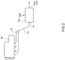
- the upstream side pressure and temperature are kept constant without being affected by a pulsation etc. of a suction pump, a constant flow rate can be obtained. Meanwhile, upon measurement of the upstream side pressure and temperature, the flow rate at that time can be calculated. Also, in the critical orifice type constant flow rate instrument like this, it is necessary to measure the flow rate characteristics, for example, determine C (sonic conductance) prior to use. In specific, a known flow rate is rendered to flow and the pressure and temperature at that time are measured so as to calculate C based on the measured values (this process also referred to as "calibration" hereinafter).
- the method of measuring the characteristics of the constant flow rate instrument is characterized in that the other dilution unit is an upstream side or downstream side dilution unit adjacent to the corresponding one dilution unit.
- a dilution mechanism pertaining to claim 4 of the present invention is constructed in a manner that, each of a plurality of dilution units is constructed such that a confluence is provided at an intermediate portion of a main flow passage connecting between an input terminal and an output terminal for leading input gas and a diluent gas flow passage provided with flow rate control means is connected to the confluence so that diluent gas of a prescribed flow rate to have a predetermined dilution ratio is introduced to the main flow passage and the plurality of dilution units are connected in series and a part or whole of the dilution units is provided with a branch point at the intermediate portion of the main flow passage so that a derivation flow passage provided with the critical orifice type constant flow rate instrument is connected to the branch point so as to derive the gas of a constant flow rate from the main flow passage.
- a dilution mechanism pertaining to claim 5 of the present invention is constructed in a manner that, each of a plurality of dilution units is constructed such that a confluence is provided at an intermediate portion of a main flow passage connecting between an input terminal and an output terminal for leading input gas and a diluent gas flow passage provided with flow rate control means is connected to the confluence so that diluent gas of a prescribed flow rate to have a predetermined dilution ratio is introduced to the main flow passage and the plurality of dilution units are connected in series and a part or whole of the dilution units is provided with a branch point at the intermediate portion of the main flow passage so that a derivation flow passage provided with the critical orifice type constant flow rate instrument is connected to the branch point so as to derive the gas of a constant flow rate from the main flow passage.
- the dilution mechanism includes an information processing device controlling the flow rate control means in a manner that the total flow rate of the respective diluent gas at this time is equal to the constant flow rate and that the dilution ratio of the flow rate of the diluent gas from the one or more other dilution units to the flow rate of the diluent gas from the corresponding one dilution unit is equal to the predetermined dilution ratio and measuring the flow rate characteristics of the corresponding critical orifice type constant flow rate instrument based on at least an upstream side pressure of the critical orifice type constant flow rate instrument in the corresponding derivation flow passage.
- a gas analyzing system includes the dilution mechanism according to claim 5 of the present invention and further includes ingredient analyzing means adapted to analyze ingredients of exhaust gas of an internal combustion engine introduced to a first-stage dilution unit and derived from a last-stage dilution unit. With this arrangement, the effect of claim 1 of the present invention and the like becomes remarkable.
- a gas analyzing system is characterized in that the ingredient analyzing means includes critical orifice type constant flow rate means inside thereof and is constructed such that only the diluent gas from the dilution unit is flowable into the ingredient analyzing means by a prescribed flow rate, wherein the information processing device measures the flow rate characteristics of the ingredient analyzing means based on at least an upstream side pressure of the ingredient analyzing means at this time.
- the gas analyzing system 100 pertaining to the present embodiment is adapted to sample a part of exhaust gas which is a measurement gas through a branch flow passage Td branched from an exhaust pipe Ex of an internal combustion engine Eg so as to count the number of solid particles PM contained therein.
- the exhaust gas is a raw exhaust gas exhausted from the internal combustion engine but may be an exhaust gas diluted through, e.g., a full-flow dilution tunnel or branch flow dilution tunnel. That is, the exhaust gas in the present application means inclusion of the exhaust gas diluted as mentioned above in addition to the raw exhaust gas.
- a reference symbol PI in FIG. 3 shows an exhaust gas introduction port.
- the exhaust gas of the internal combustion engine Eg is led from the branch flow passage Td to the inside through the exhaust gas introduction port PI.
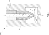
- the exhaust gas is diluted by a dilution mechanism 3 provided in the gas analyzing system and thereafter led to particulate matters counting means CPC that is one kind of ingredient analyzing means and connected to the subsequent stage thereof so that the number of PM contained inside thereof is counted.
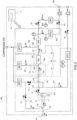
- the dilution mechanism 3 includes three-stage dilution units 31, 32 and 33 provided in series.
- the dilution units 31, 32 and 33 are respectively provided with, as basic components, input terminals 31i, 32i and 33i introducing the input gas, output terminals 31o, 32o and 33o deriving the gas, main flow passages L1, L2 and L3 connected between the input terminals 31i, 32i and 33i and the output terminals 31o, 32o and 33o, and diluent gas flow passages D1, D2 and D3 connected to confluences L1a, L2a and L3a provided at an intermediate portion of the main flow passages L1, L2 and L3.
- the diluent gas flow passages D1, D2 and D3 are respectively provided with flow rate control means (herein, mass flow controllers) MFC1, MFC2 and MFC3.
- the flow rates of inflow diluent gases are controlled by the flow rate control means MFC1, MFC2 and MFC3 so that the input gases are diluted at prescribed dilution ratios so as to output the mixed gas of the diluted gases.
- the input terminal 31i is connected to the exhaust gas introduction port PI and the output terminal 31o thereof is connected to the input terminal 32i of the middle-stage dilution unit 32.
- a branch point L1b is provided in the downstream side than the confluence L1a in the main flow passage L1 so that a derivation flow passage E1 is connected to the branch point L1b.
- the middle-stage dilution unit 32 has the basic components mentioned before wherein the output terminal 32o thereof is connected to the last-stage dilution unit 33 through an evaporator unit EU.
- This dilution unit 32 is not provided with a derivation flow passage as in the first-stage dilution unit 31.
- the evaporator unit EU is provided here having a main object to remove volatile particles and is kept at a temperature of, e.g., about 300 - 400 °C.
- the main flow passages L1 and L2 in the first-stage and middle-stage dilution units 31 and 32 extending from the dust removal means 2 to the evaporator unit EU and the diluent gas flow passage D2 except the vicinity of the flow rate control means MFC1 in the middle-stage dilution unit 32 are kept at a second temperature by a temperature controller T2 (herein, e.g., about 150 - 250 °C). This is to prevent adhesion and agglomeration etc. of PM to an inner wall of the pipe so as to suppress the counting error.
- a temperature controller T2 herein, e.g., about 150 - 250 °C
- the last-stage dilution unit 33 has a configuration that the input terminal 33i thereof is connected to an outlet of the evaporator unit EU and the output terminal 33o thereof is connected to the particulate matters counting means CPC.
- a branch point L3b is provided in the downstream side than the confluence L3a in the main flow passage L3 so that a derivation flow passage E3 is connected to the branch point L3b.
- a suction pump P2 is provided at a distal end of the derivation flow passage E3 and a critical orifice type constant flow rate instrument CFO2 is provided at the intermediate portion thereof so that a prescribed constant flow rate gas of the entire gas flowing in the main flow passage L3 is derived from the derivation flow passage E3 and the remaining gas is introduced to the particulate matters counting means CPC.
- the outlet of the particulate matters counting means CPC is connected to a distal end portion of the derivation flow passage E3 and the suction pump P2 is commonly used for the derivation flow passage 3 and the particulate matters counting means CPC.
- an information processing device 7 for controlling the flow rate control means and the like.
- This information processing device is so-called a general-purpose or special-purpose computer including a CPU, a memory, input means, a display and the like to be operated in co-operation with the CPU and peripheral equipment in accordance with a predetermined program stored in the memory.
- the information processing device 7 is configured to act at least a function of a diluent gas control unit 71 in accordance with the program.
- R d1 , R d2 and R d3 are represented by following formulae (1) to (3):
- R d 1 q in 1 / q in 1 + q d 1
- R d2 q in2 / q in2 + q d2
- R d3 q in3 / q in3 + q d3
- the flow rate control means MFC1 having a maximum flow rate of 5.5 L/min
- flow rate control means MFC2 having a maximum flow rate of 1.0 L/min
- flow rate control means MFC3 having a maximum flow rate of 5.5 L/min are used.
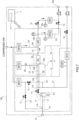
- the characteristic measurement (calibration) prior to use of the respective constant flow rate instruments CFO1 and CFO2 is performed as follows.
- valves V1, V3, V4 and V5 are closed while the valves V2 and V6 are kept open, and the entire diluent gas only from and flowing through the diluent gas flow passage D1 of the first-stage dilution unit 31 and the diluent gas flow passage D2 of the middle-stage dilution unit 32 are rendered to flow into the constant flow rate instrument CFO1 of the first-stage dilution unit 31.
- the temperature control mechanism T2 is adjusted so that the gas at a temperature substantially equal to that in use is rendered to flow into the constant flow rate instrument CFO1.
- the upstream side pressure and temperature of the constant flow rate instrument CFO1 under this condition are measured by the pressure sensor P1 and the temperature sensor T1, and the measurement values are substituted into, e.g., Formula (A) mentioned in Paragraph [0005] so as to specify the sonic conductance C of the constant flow rate instrument CFO1.
- each of the operations pertaining to the calibrations mentioned above such as, e.g., opening and closing of the valves V1 to V6, controls of the flow rate control means MFC1 to MFC3, measuring of the pressure and temperature and calculation / storing of the sonic conductance C is all automatically performed by the information processing device 7 and the operator is merely required to input instructions of performing a calibration.
- the setting or calibration may be manually performed in sequence by an operator.
- a flow rate calibration of the particulate matters counting means CPC is also performed.
- the valves V1, V2, V3 and V6 are closed while the valves V4 and V5 are kept open, and the entire diluent gas only from and flowing through the diluent gas flow passage D3 of the last-stage dilution unit 33 and the diluent gas flow passage D2 of the middle-stage dilution unit 32 are rendered to flow into the constant flow rate instrument CFO2 and the slit A3 of the particulate matters counting means CPC.
- the evaporator unit EU is operated and the temperature control mechanism T2 is adjusted so that the temperature of the gas is kept to be substantially equal to that in use.
Landscapes
- Chemical & Material Sciences (AREA)
- Life Sciences & Earth Sciences (AREA)
- Health & Medical Sciences (AREA)
- Pathology (AREA)
- General Physics & Mathematics (AREA)
- Physics & Mathematics (AREA)
- Engineering & Computer Science (AREA)
- Analytical Chemistry (AREA)
- Biochemistry (AREA)
- General Health & Medical Sciences (AREA)
- Immunology (AREA)
- Molecular Biology (AREA)
- Biomedical Technology (AREA)
- Dispersion Chemistry (AREA)
- Combustion & Propulsion (AREA)
- Food Science & Technology (AREA)
- Medicinal Chemistry (AREA)
- Sampling And Sample Adjustment (AREA)
Claims (8)
- Verfahren zum Messen der Eigenschaften eines Instruments (CFO1, CFO2) mit konstantem Volumenstrom vom Messblendentyp, das für einen Verdünnungsmechanismus (3) verwendet wird, der auf solch eine Weise aufgebaut ist, dassjede einer Vielzahl von Verdünnungseinheiten (31, 32, 33), die in Reihe geschaltet sind, so aufgebaut ist, dass eine Einmündung (Lla, L2a, L3a) an einem Zwischenabschnitt eines Hauptstromkanals (L1, L2, L3) vorgesehen ist, der zwischen einem Eingangsanschluss (31i, 32i, 33i) und einem Ausgangsanschluss (31o, 32o, 33o) zum Führen von eingespeistem Gas verbindet;jede der Verdünnungseinheiten (31, 32, 33) einen mit einem Volumenstrom-Steuerungsmittel (MFC1, MFC2, MFC3) versehenen Verdünnungsgasstromkanal (D1, D2, D3) aufweist, der mit der Einmündung (Lla, L2a, L3a) verbunden ist, welche Volumenstrom-Steuerungsmittel (MFC1, MFC2, MFC3) so konfiguriert sind, dass sie während des Betriebs des Verdünnungsmechanismus (3) Verdünnungsgas mit einem vorgeschriebenen Volumenstrom in den Hauptstromkanal (L1, L2, L3) einleiten, um ein vorbestimmtes Verdünnungsverhältnis zu haben; undzumindest eine der Verdünnungseinheiten (31, 33) einen Verzweigungspunkt (L1b, L3b) an dem Zwischenabschnitt des Hauptstromkanals (L1, L2, L3) aufweist, so dass ein Ableitungsstromkanal (E1, E3), der mit dem Instrument (CFO1, CFO2) mit konstantem Volumenstrom vom Messblendentyp versehen ist, mit dem Verzweigungspunkt (L1b, L3b) verbunden ist, um Gas mit einem konstanten Volumenstrom vom Hauptstromkanal (L1, L3) während des Betriebs des Verdünnungsmechanismus (3) abzuleiten,wobei das Verfahren dadurch gekennzeichnet ist, dass für eine Kalibrierung des Instruments (CFO1, CFO2) mit konstantem Volumenstrom vom Messblendentypdas Verdünnungsgas vom Verdünnungsgasstromkanal (D1, D3) der einen Verdünnungseinheit (31, 33) mit dem Verzweigungspunkt (L1b, L3b) und das Verdünnungsgas von den Verdünnungsgasstromkanälen (D2) von einer oder mehreren anderen Verdünnungseinheiten (32) in den Ableitungsstromkanal (E1, E3) der einen Verdünnungseinheit (31, 33) eingeleitet werden, indem die jeweiligen Volumenstrom-Steuerungsmittel (MFC1, MFC2, MFC3) in einer Art und Weise gesteuert werden, dass deren Gesamtvolumenstrom gleich dem konstanten Volumenstrom ist, der auch während des Betriebs des Verdünnungsmechanismus (3) genutzt wird, und dass der Volumenstrom des Verdünnungsgases von der einen Verdünnungseinheit (31, 33) mit dem Verzweigungspunkt (L1b, L3b) gleich dem vorgeschriebenen Volumenstrom ist, der ebenfalls während des Betriebs des Verdünnungsmechanismus (3) genutzt wird, unddie Volumenstromeigenschaften des entsprechenden Instruments (CFO1, CFO2) mit konstantem Volumenstrom vom Messblendentyp basierend auf zumindest einem Druck auf der stromaufwärts gelegenen Seite des Instruments (CFO1, CFO2) mit konstantem Volumenstrom vom Messblendentyp im entsprechenden Ableitungsstromkanal (E1, E3) gemessen werden.
- Verfahren zum Messen der Eigenschaften eines Instruments (CFO1, CFO2) mit konstantem Volumenstrom vom Messblendentyp, das für einen Verdünnungsmechanismus (3) verwendet wird, der auf solch eine Weise aufgebaut ist, dassjede einer Vielzahl von Verdünnungseinheiten (31, 32, 33), die in Reihe geschaltet sind, so aufgebaut ist, dass eine Einmündung (Lla, L2a, L3a) an einem Zwischenabschnitt eines Hauptstromkanals (L1, L2, L3) vorgesehen ist, der zwischen einem Eingangsanschluss (31i, 32i, 33i) und einem Ausgangsanschluss (31o, 32o, 33o) zum Führen von eingespeistem Gas verbindet;jede der Verdünnungseinheiten (31, 32, 33) einen mit einem Volumenstrom-Steuerungsmittel (MFC1, MFC2, MFC3) versehenen Verdünnungsgasstromkanal (D1, D2, D3) aufweist, der mit der Einmündung (Lla, L2a, L3a) verbunden ist, welche Volumenstrom-Steuerungsmittel (MFC1, MFC2, MFC3) so konfiguriert sind, dass sie während des Betriebs des Verdünnungsmechanismus (3) Verdünnungsgas mit einem vorgeschriebenen Volumenstrom in den Hauptstromkanal (L1, L2, L3) einleiten, um ein vorbestimmtes Verdünnungsverhältnis zu haben; undzumindest eine der Verdünnungseinheiten (31, 33) einen Verzweigungspunkt (L1b, L3b) an dem Zwischenabschnitt des Hauptstromkanals (L1, L2, L3) aufweist, so dass ein Ableitungsstromkanal (E1, E3), der mit dem Instrument (CFO1, CFO2) mit konstantem Volumenstrom vom Messblendentyp versehen ist, mit dem Verzweigungspunkt (L1b, L3b) verbunden ist, um Gas mit einem konstanten Volumenstrom vom Hauptstromkanal (L1, L3) während des Betriebs des Verdünnungsmechanismus (3) abzuleiten,wobei das Verfahren dadurch gekennzeichnet ist, dass für eine Kalibrierung des Instruments (CFO1, CFO2) mit konstantem Volumenstrom vom Messblendentypdas Verdünnungsgas vom Verdünnungsgasstromkanal (D1, D3) der einen Verdünnungseinheit (31, 33) mit dem Verzweigungspunkt (L1b, L3b) und das Verdünnungsgas von den Verdünnungsgasstromkanälen (D2) von einer oder mehreren anderen Verdünnungseinheiten (32) in den Ableitungsstromkanal (E1, E3) der einen Verdünnungseinheit (31, 33) eingeleitet werden, indem die jeweiligen Volumenstrom-Steuerungsmittel (MFC1, MFC2, MFC3) in einer Art und Weise gesteuert werden, dass deren Gesamtvolumenstrom gleich dem konstanten Volumenstrom ist, der auch während des Betriebs des Verdünnungsmechanismus (3) genutzt wird, und dass ein Verdünnungsverhältnis des Volumenstroms des Verdünnungsgases von der einen oder den mehreren anderen Verdünnungseinheiten (32) zu dem Volumenstrom des Verdünnungsgases von der einen Verdünnungseinheit (31, 33) gleich dem vorbestimmten Verdünnungsverhältnis ist, das ebenfalls während des Betriebs des Verdünnungsmechanismus (3) genutzt wird, unddie Volumenstromeigenschaften des entsprechenden Instruments (CFO1, CFO2) mit konstantem Volumenstrom vom Messblendentyp basierend auf zumindest einem Druck auf der stromaufwärts gelegenen Seite des Instruments (CFO1, CFO2) mit konstantem Volumenstrom vom Messblendentyp im entsprechenden Ableitungsstromkanal (E1, E3) gemessen werden.
- Verfahren zum Messen der Eigenschaften eines Instruments (CFO1, CFO2) mit konstantem Volumenstrom vom Messblendentyp nach Anspruch 1 oder 2, wobei die eine oder die mehreren anderen Verdünnungseinheiten (32) Verdünnungseinheiten (32) auf der stromaufwärts gelegenen Seite oder der stromabwärts gelegenen Seite sind, die der einen Verdünnungseinheit (31, 33) mit dem Verzweigungspunkt (L1b, L3b) benachbart sind.
- Verdünnungsmechanismus (3), aufweisend:eine Vielzahl von Verdünnungseinheiten (31, 32, 33), die in Reihe geschaltet sind, wobeijede der Vielzahl von Verdünnungseinheiten (31, 32, 33) so aufgebaut ist, dass eine Einmündung (Lla, L2a, L3a) an einem Zwischenabschnitt eines Hauptstromkanals (L1, L2, L3) vorgesehen ist, der zwischen einem Eingangsanschluss (31i, 32i, 33i) und einem Ausgangsanschluss (31o, 32o, 33o) zum Führen von eingespeistem Gas verbindet, undjede der Vielzahl von Verdünnungseinheiten (31, 32, 33) einen mit einem Volumenstrom-Steuerungsmittel (MFC1, MFC2, MFC3) versehenen Verdünnungsgasstromkanal (D1, D2, D3) aufweist, der mit der Einmündung (Lla, L2a, L3a) verbunden ist, welche Volumenstrom-Steuerungsmittel (MFC1, MFC2, MFC3) so konfiguriert sind, dass sie während des Betriebs des Verdünnungsmechanismus (3) Verdünnungsgas mit einem vorgeschriebenen Volumenstrom in den Hauptstromkanal (L1, L2, L3) einleiten, um ein vorbestimmtes Verdünnungsverhältnis zu haben;zumindest eine der Verdünnungseinheiten (31, 33) einen Verzweigungspunkt (L1b, L3b) an einem Zwischenabschnitt des Hauptstromkanals (L1, L2, L3) aufweist, so dass ein Ableitungsstromkanal (E1, E3), der mit dem Instrument (CFO1, CFO2) mit konstantem Volumenstrom vom Messblendentyp versehen ist, mit dem Verzweigungspunkt (L1b, L3b) verbunden ist, um das Gas mit einem konstanten Volumenstrom vom Hauptstromkanal (L1, L3) während des Betriebs des Verdünnungsmechanismus (3) abzuleiten,dadurch gekennzeichnet ist, dass für eine Kalibrierung des Instruments (CFO1, CFO2) mit konstantem Volumenstrom vom Messblendentyp der Verdünnungsmechanismus (3) so konfiguriert ist, dass erdas Verdünnungsgas vom Verdünnungsgasstromkanal (D1, D3) der einen Verdünnungseinheit (31, 33) mit dem Verzweigungspunkt (L1b, L3b) und das Verdünnungsgas von den Verdünnungsgasstromkanälen (D2) von einer oder mehreren anderen Verdünnungseinheiten (32) in den Ableitungsstromkanal (E1, E3) der einen Verdünnungseinheit (31, 33) einleitet, indem die jeweiligen Volumenstrom-Steuerungsmittel (MFC1, MFC2, MFC3) mit einer Informationsverarbeitungsvorrichtung (7) des Verdünnungsmechanismus (3) in einer Art und Weise gesteuert werden, dass deren Gesamtvolumenstrom gleich dem konstanten Volumenstrom ist, der auch während des Betriebs des Verdünnungsmechanismus (3) genutzt wird, und dass der Volumenstrom des Verdünnungsgases von der einen Verdünnungseinheit (31, 33) mit dem Verzweigungspunkt (L1b, L3b) gleich dem vorgeschriebenen Volumenstrom ist, der ebenfalls während des Betriebs des Verdünnungsmechanismus (3) genutzt wird, unddafür geeignet ist, mit der Informationsverarbeitungsvorrichtung (7) die Volumenstromeigenschaften des entsprechenden Instruments (CFO1, CFO2) mit konstantem Volumenstrom vom Messblendentyp basierend auf zumindest einem Druck auf der stromaufwärts gelegenen Seite des Instruments (CFO1, CFO2) mit konstantem Volumenstrom vom Messblendentyp im entsprechenden Ableitungsstromkanal (E1, E3) zu messen.
- Verdünnungsmechanismus (3), aufweisend:eine Vielzahl von Verdünnungseinheiten (31, 32, 33), die in Reihe geschaltet sind, wobeijede einer Vielzahl von Verdünnungseinheiten (31, 32, 33) so aufgebaut ist, dass eine Einmündung (Lla, L2a, L3a) an einem Zwischenabschnitt eines Hauptstromkanals (L1, L2, L3) vorgesehen ist, der zwischen einem Eingangsanschluss (31i, 32i, 33i) und einem Ausgangsanschluss (31o, 32o, 33o) zum Führen von eingespeistem Gas verbindet, undjede der Vielzahl von Verdünnungseinheiten (31, 32, 33) einen mit einem Volumenstrom-Steuerungsmittel (MFC1, MFC2, MFC3) versehenen Verdünnungsgasstromkanal (D1, D2, D3) aufweist, der mit der Einmündung (Lla, L2a, L3a) verbunden ist, welche Volumenstrom-Steuerungsmittel (MFC1, MFC2, MFC3) so konfiguriert sind, dass sie während des Betriebs des Verdünnungsmechanismus (3) Verdünnungsgas mit einem vorgeschriebenen Volumenstrom in den Hauptstromkanal (L1, L2, L3) einleiten, um ein vorbestimmtes Verdünnungsverhältnis zu haben; undzumindest eine der Verdünnungseinheiten (31, 33) einen Verzweigungspunkt (L1b, L3b) an einem Zwischenabschnitt des Hauptstromkanals (L1, L2, L3) aufweist, so dass ein Ableitungsstromkanal (E1, E3), der mit dem Instrument (CFO1, CFO2) mit konstantem Volumenstrom vom Messblendentyp versehen ist, mit dem Verzweigungspunkt (L1b, L3b) verbunden ist, um Gas mit einem konstanten Volumenstrom vom Hauptstromkanal (L1, L3) während des Betriebs des Verdünnungsmechanismus (3) abzuleiten,dadurch gekennzeichnet ist, dass für eine Kalibrierung des Instruments (CFO1, CFO2) mit konstantem Volumenstrom vom Messblendentyp der Verdünnungsmechanismus (3) so konfiguriert ist, dass erdas Verdünnungsgas vom Verdünnungsgasstromkanal (D1, D3) der einen Verdünnungseinheit (31, 33) mit dem Verzweigungspunkt (L1b, L3b) und das Verdünnungsgas von den Verdünnungsgasstromkanälen (D2) von einer oder mehreren anderen Verdünnungseinheiten (32) in den Ableitungsstromkanal (E1, E3) der einen Verdünnungseinheit (31, 33) einleitet, indem die jeweiligen Volumenstrom-Steuerungsmittel (MFC1, MFC2, MFC3) mit einer Informationsverarbeitungsvorrichtung (7) des Verdünnungsmechanismus (3) in einer Art und Weise gesteuert werden, dass deren Gesamtvolumenstrom gleich dem konstanten Volumenstrom ist, der auch während des Betriebs des Verdünnungsmechanismus (3) genutzt wird, und dass ein Verdünnungsverhältnis des Volumenstroms des Verdünnungsgases von der einen oder den mehreren anderen Verdünnungseinheiten (32) zu dem Volumenstrom des Verdünnungsgases von der einen Verdünnungseinheit (31, 33) gleich dem vorbestimmten Verdünnungsverhältnis ist, das ebenfalls während des Betriebs des Verdünnungsmechanismus (3) genutzt wird; unddafür geeignet ist, mit der Informationsverarbeitungsvorrichtung (7) die Volumenstromeigenschaften des entsprechenden Instruments (CFO1, CFO2) mit konstantem Volumenstrom vom Messblendentyp basierend auf zumindest einem Druck auf der stromaufwärts gelegenen Seite des Instruments (CFO1, CFO2) mit konstantem Volumenstrom vom Messblendentyp im entsprechenden Ableitungsstromkanal (E1, E3) zu messen.
- Gasanalysesystem (100) mit dem Verdünnungsmechanismus (3) nach Anspruch 4 oder 5, ferner aufweisend ein Inhaltsstoffe analysierendes Mittel (CPC), das dafür geeignet ist, Inhaltsstoffe eines Abgases eines Verbrennungsmotors (Eg) zu analysieren, das in eine Verdünnungseinheit (31) einer ersten Stufe eingeleitet und von einer Verdünnungsstufe (33) einer letzten Stufe abgeleitet wird.
- Gasanalysesystem (100) nach Anspruch 6, wobei das Inhaltsstoffe analysierende Mittel (CPC) in seinem Inneren ein Instrument (CFO2) mit konstantem Volumenstrom vom Messblendentyp aufweist und so aufgebaut ist, dass nur das Verdünnungsgas von der Verdünnungseinheit (33) in das Inhaltsstoffe analysierende Mittel (CPC) gemäß einem vorgeschriebenen Volumenstrom strömen kann, und wobei
die Informationsverarbeitungsvorrichtung (7) dafür geeignet ist, die Volumenstromeigenschaften des Inhaltsstoffe analysierenden Mittels (CPC) basierend auf zumindest einem Druck auf der stromaufwärts gelegenen Seite des Inhaltsstoffe analysierenden Mittels (CPC) zu dieser Zeit zu messen. - Gasanalysesystem (100) nach Anspruch 6 oder 7, wobei das Inhaltsstoffe analysierende Mittel (CPC) ein Zähler für partikelförmige Stoffe ist, der dafür konfiguriert ist, im Abgas enthaltene partikelförmige Stoffe zu zählen.
Applications Claiming Priority (1)
| Application Number | Priority Date | Filing Date | Title |
|---|---|---|---|
| JP2011003867 | 2011-01-12 |
Publications (3)
| Publication Number | Publication Date |
|---|---|
| EP2477023A2 EP2477023A2 (de) | 2012-07-18 |
| EP2477023A3 EP2477023A3 (de) | 2018-04-25 |
| EP2477023B1 true EP2477023B1 (de) | 2024-07-03 |
Family
ID=45571336
Family Applications (1)
| Application Number | Title | Priority Date | Filing Date |
|---|---|---|---|
| EP12000134.2A Active EP2477023B1 (de) | 2011-01-12 | 2012-01-11 | Verfahren zur Messung von Eigenschaften eines Instruments mit konstanter Durchflussrate nach dem kritischen "Orifice"-Prinzip zur Verwendung in einem mehrstufigen Verdünnungsmechanismus |
Country Status (4)
| Country | Link |
|---|---|
| US (1) | US9140631B2 (de) |
| EP (1) | EP2477023B1 (de) |
| JP (1) | JP5837415B2 (de) |
| CN (1) | CN102589959B (de) |
Families Citing this family (7)
| Publication number | Priority date | Publication date | Assignee | Title |
|---|---|---|---|---|
| US10156500B2 (en) | 2012-06-01 | 2018-12-18 | Horiba, Ltd. | Exhaust gas dilution device |
| JP6093654B2 (ja) * | 2013-06-03 | 2017-03-08 | 株式会社堀場製作所 | 排ガスサンプリング装置 |
| JP6918927B2 (ja) * | 2016-09-14 | 2021-08-11 | ジェイソン・ポール・ジョンソン | 受動型エアロゾル希釈器メカニズム |
| JP7461951B2 (ja) * | 2019-07-22 | 2024-04-04 | 株式会社堀場製作所 | 排ガス分析装置、ガス供給方法、及び排ガスサンプリング装置 |
| CN111203118A (zh) * | 2020-01-17 | 2020-05-29 | 上海理工大学 | 一种分段调节稀释装置及系统 |
| FR3108981B1 (fr) * | 2020-04-01 | 2022-04-01 | Pfeiffer Vacuum Technology AG | Station et procédé de mesure de la contamination moléculaire véhiculée par l’air |
| TW202413916A (zh) * | 2022-06-16 | 2024-04-01 | 日商堀場製作所股份有限公司 | 氣體連續分析系統及氣體連續分析方法 |
Family Cites Families (11)
| Publication number | Priority date | Publication date | Assignee | Title |
|---|---|---|---|---|
| JP2000028499A (ja) * | 1998-07-15 | 2000-01-28 | Farm Tec:Kk | 排気ガス中の混合物質捕集装置 |
| WO2001084111A1 (en) * | 2000-04-28 | 2001-11-08 | Pp & L Resources, Inc. | Emission monitoring system and method |
| JP4195819B2 (ja) | 2003-01-17 | 2008-12-17 | 忠弘 大見 | 弗化水素ガスの流量制御方法及びこれに用いる弗化水素ガス用流量制御装置 |
| US7798020B2 (en) * | 2004-07-21 | 2010-09-21 | Sensors, Inc. | Fast response proportional sampling system and method for exhaust gas analysis |
| JP2006194726A (ja) | 2005-01-13 | 2006-07-27 | Mazda Motor Corp | Pm粒子数計測装置 |
| US20090218051A1 (en) * | 2006-03-16 | 2009-09-03 | Francisco Cereceda Balic | Semiautomatic device, a system and an operation method for solvent evaporation with the help of analytical gas for atmospheric sample concentration, destined to identify and quantify organic chemical compounds with toxic properties. |
| FR2904689B1 (fr) * | 2006-08-01 | 2009-01-16 | Alcatel Sa | Organe de prelevement de gaz |
| US7647810B2 (en) * | 2006-12-21 | 2010-01-19 | Horiba Ltd. | Solid particle counting system with flow meter upstream of evaporation unit |
| JP4749323B2 (ja) * | 2006-12-28 | 2011-08-17 | 株式会社堀場製作所 | 粒子数計測システム |
| JP5489324B2 (ja) * | 2009-04-17 | 2014-05-14 | 株式会社堀場製作所 | 粒子数計測システム |
| JP5476193B2 (ja) * | 2009-04-07 | 2014-04-23 | 株式会社堀場製作所 | 粒子数計測システム |
-
2011
- 2011-12-27 JP JP2011286665A patent/JP5837415B2/ja not_active Expired - Fee Related
-
2012
- 2012-01-11 EP EP12000134.2A patent/EP2477023B1/de active Active
- 2012-01-11 CN CN201210007970.5A patent/CN102589959B/zh not_active Expired - Fee Related
- 2012-01-12 US US13/348,826 patent/US9140631B2/en not_active Expired - Fee Related
Also Published As
| Publication number | Publication date |
|---|---|
| EP2477023A3 (de) | 2018-04-25 |
| US9140631B2 (en) | 2015-09-22 |
| EP2477023A2 (de) | 2012-07-18 |
| CN102589959A (zh) | 2012-07-18 |
| JP2012159496A (ja) | 2012-08-23 |
| US20120174989A1 (en) | 2012-07-12 |
| CN102589959B (zh) | 2015-10-28 |
| JP5837415B2 (ja) | 2015-12-24 |
Similar Documents
| Publication | Publication Date | Title |
|---|---|---|
| EP2477023B1 (de) | Verfahren zur Messung von Eigenschaften eines Instruments mit konstanter Durchflussrate nach dem kritischen "Orifice"-Prinzip zur Verwendung in einem mehrstufigen Verdünnungsmechanismus | |
| JP5492001B2 (ja) | 排ガス分析システム | |
| JP6069034B2 (ja) | 排ガスサンプリング装置 | |
| US20090044599A1 (en) | Quantitative Aerosol Dilution System | |
| EP2515095A1 (de) | Abgaserfassungsvorrichtung | |
| JP6173309B2 (ja) | 排ガス希釈装置 | |
| EP3088861B1 (de) | Messsystem und messverfahren für abgase | |
| CN101680821A (zh) | 废气取样稀释器及方法 | |
| EP1864104B1 (de) | Kontinuierlich arbeitende verdünnungsvorrichtung mit breitem arbeitsbereich | |
| CN105987831B (zh) | 排气取样装置、排气分析系统和排气稀释方法 | |
| CN109668762B (zh) | 排气分析装置、排气分析系统和程序存储介质 | |
| EP3513162A1 (de) | Passiver aerosolverdünnermechanismus | |
| CN106770940B (zh) | 一种气体分析仪系统的检查装置 | |
| JP5476193B2 (ja) | 粒子数計測システム | |
| US7389703B2 (en) | Sampler for engine exhaust dilution | |
| JP5087142B2 (ja) | 揮発性粒子除去装置のための較正ユニット | |
| US20080087107A1 (en) | Particulate sampler and dilution gas flow device arrangement for an exhaust sampling system | |
| JP4749323B2 (ja) | 粒子数計測システム |
Legal Events
| Date | Code | Title | Description |
|---|---|---|---|
| PUAI | Public reference made under article 153(3) epc to a published international application that has entered the european phase |
Free format text: ORIGINAL CODE: 0009012 |
|
| AK | Designated contracting states |
Kind code of ref document: A2 Designated state(s): AL AT BE BG CH CY CZ DE DK EE ES FI FR GB GR HR HU IE IS IT LI LT LU LV MC MK MT NL NO PL PT RO RS SE SI SK SM TR |
|
| AX | Request for extension of the european patent |
Extension state: BA ME |
|
| RIC1 | Information provided on ipc code assigned before grant |
Ipc: G01N 15/10 20060101ALI20171214BHEP Ipc: G01N 1/22 20060101AFI20171214BHEP Ipc: G01N 33/00 20060101ALI20171214BHEP Ipc: G01N 15/06 20060101ALI20171214BHEP |
|
| PUAL | Search report despatched |
Free format text: ORIGINAL CODE: 0009013 |
|
| AK | Designated contracting states |
Kind code of ref document: A3 Designated state(s): AL AT BE BG CH CY CZ DE DK EE ES FI FR GB GR HR HU IE IS IT LI LT LU LV MC MK MT NL NO PL PT RO RS SE SI SK SM TR |
|
| AX | Request for extension of the european patent |
Extension state: BA ME |
|
| RIC1 | Information provided on ipc code assigned before grant |
Ipc: G01N 15/10 20060101ALI20180320BHEP Ipc: G01N 33/00 20060101ALI20180320BHEP Ipc: G01N 1/22 20060101AFI20180320BHEP Ipc: G01N 15/06 20060101ALI20180320BHEP |
|
| STAA | Information on the status of an ep patent application or granted ep patent |
Free format text: STATUS: REQUEST FOR EXAMINATION WAS MADE |
|
| 17P | Request for examination filed |
Effective date: 20181016 |
|
| RBV | Designated contracting states (corrected) |
Designated state(s): AL AT BE BG CH CY CZ DE DK EE ES FI FR GB GR HR HU IE IS IT LI LT LU LV MC MK MT NL NO PL PT RO RS SE SI SK SM TR |
|
| STAA | Information on the status of an ep patent application or granted ep patent |
Free format text: STATUS: EXAMINATION IS IN PROGRESS |
|
| 17Q | First examination report despatched |
Effective date: 20200204 |
|
| P01 | Opt-out of the competence of the unified patent court (upc) registered |
Effective date: 20231108 |
|
| GRAP | Despatch of communication of intention to grant a patent |
Free format text: ORIGINAL CODE: EPIDOSNIGR1 |
|
| STAA | Information on the status of an ep patent application or granted ep patent |
Free format text: STATUS: GRANT OF PATENT IS INTENDED |
|
| INTG | Intention to grant announced |
Effective date: 20240313 |
|
| RIN1 | Information on inventor provided before grant (corrected) |
Inventor name: HANADA, KAZUO Inventor name: SHINOHARA, MASAYOSHI Inventor name: OTSUKI, YOSHINORI |
|
| GRAS | Grant fee paid |
Free format text: ORIGINAL CODE: EPIDOSNIGR3 |
|
| GRAA | (expected) grant |
Free format text: ORIGINAL CODE: 0009210 |
|
| STAA | Information on the status of an ep patent application or granted ep patent |
Free format text: STATUS: THE PATENT HAS BEEN GRANTED |
|
| AK | Designated contracting states |
Kind code of ref document: B1 Designated state(s): AL AT BE BG CH CY CZ DE DK EE ES FI FR GB GR HR HU IE IS IT LI LT LU LV MC MK MT NL NO PL PT RO RS SE SI SK SM TR |
|
| REG | Reference to a national code |
Ref country code: CH Ref legal event code: EP |
|
| REG | Reference to a national code |
Ref country code: DE Ref legal event code: R096 Ref document number: 602012080911 Country of ref document: DE |
|
| REG | Reference to a national code |
Ref country code: LT Ref legal event code: MG9D |
|
| REG | Reference to a national code |
Ref country code: NL Ref legal event code: MP Effective date: 20240703 |
|
| PG25 | Lapsed in a contracting state [announced via postgrant information from national office to epo] |
Ref country code: PT Free format text: LAPSE BECAUSE OF FAILURE TO SUBMIT A TRANSLATION OF THE DESCRIPTION OR TO PAY THE FEE WITHIN THE PRESCRIBED TIME-LIMIT Effective date: 20241104 |
|
| REG | Reference to a national code |
Ref country code: AT Ref legal event code: MK05 Ref document number: 1700284 Country of ref document: AT Kind code of ref document: T Effective date: 20240703 |
|
| PG25 | Lapsed in a contracting state [announced via postgrant information from national office to epo] |
Ref country code: NL Free format text: LAPSE BECAUSE OF FAILURE TO SUBMIT A TRANSLATION OF THE DESCRIPTION OR TO PAY THE FEE WITHIN THE PRESCRIBED TIME-LIMIT Effective date: 20240703 |
|
| PG25 | Lapsed in a contracting state [announced via postgrant information from national office to epo] |
Ref country code: PT Free format text: LAPSE BECAUSE OF FAILURE TO SUBMIT A TRANSLATION OF THE DESCRIPTION OR TO PAY THE FEE WITHIN THE PRESCRIBED TIME-LIMIT Effective date: 20241104 Ref country code: NL Free format text: LAPSE BECAUSE OF FAILURE TO SUBMIT A TRANSLATION OF THE DESCRIPTION OR TO PAY THE FEE WITHIN THE PRESCRIBED TIME-LIMIT Effective date: 20240703 |
|
| PG25 | Lapsed in a contracting state [announced via postgrant information from national office to epo] |
Ref country code: NO Free format text: LAPSE BECAUSE OF FAILURE TO SUBMIT A TRANSLATION OF THE DESCRIPTION OR TO PAY THE FEE WITHIN THE PRESCRIBED TIME-LIMIT Effective date: 20241003 |
|
| PG25 | Lapsed in a contracting state [announced via postgrant information from national office to epo] |
Ref country code: GR Free format text: LAPSE BECAUSE OF FAILURE TO SUBMIT A TRANSLATION OF THE DESCRIPTION OR TO PAY THE FEE WITHIN THE PRESCRIBED TIME-LIMIT Effective date: 20241004 Ref country code: FI Free format text: LAPSE BECAUSE OF FAILURE TO SUBMIT A TRANSLATION OF THE DESCRIPTION OR TO PAY THE FEE WITHIN THE PRESCRIBED TIME-LIMIT Effective date: 20240703 Ref country code: PL Free format text: LAPSE BECAUSE OF FAILURE TO SUBMIT A TRANSLATION OF THE DESCRIPTION OR TO PAY THE FEE WITHIN THE PRESCRIBED TIME-LIMIT Effective date: 20240703 |
|
| PG25 | Lapsed in a contracting state [announced via postgrant information from national office to epo] |
Ref country code: BG Free format text: LAPSE BECAUSE OF FAILURE TO SUBMIT A TRANSLATION OF THE DESCRIPTION OR TO PAY THE FEE WITHIN THE PRESCRIBED TIME-LIMIT Effective date: 20240703 |
|
| PG25 | Lapsed in a contracting state [announced via postgrant information from national office to epo] |
Ref country code: LV Free format text: LAPSE BECAUSE OF FAILURE TO SUBMIT A TRANSLATION OF THE DESCRIPTION OR TO PAY THE FEE WITHIN THE PRESCRIBED TIME-LIMIT Effective date: 20240703 |
|
| PG25 | Lapsed in a contracting state [announced via postgrant information from national office to epo] |
Ref country code: IS Free format text: LAPSE BECAUSE OF FAILURE TO SUBMIT A TRANSLATION OF THE DESCRIPTION OR TO PAY THE FEE WITHIN THE PRESCRIBED TIME-LIMIT Effective date: 20241103 Ref country code: AT Free format text: LAPSE BECAUSE OF FAILURE TO SUBMIT A TRANSLATION OF THE DESCRIPTION OR TO PAY THE FEE WITHIN THE PRESCRIBED TIME-LIMIT Effective date: 20240703 |
|
| PG25 | Lapsed in a contracting state [announced via postgrant information from national office to epo] |
Ref country code: HR Free format text: LAPSE BECAUSE OF FAILURE TO SUBMIT A TRANSLATION OF THE DESCRIPTION OR TO PAY THE FEE WITHIN THE PRESCRIBED TIME-LIMIT Effective date: 20240703 Ref country code: CZ Free format text: LAPSE BECAUSE OF FAILURE TO SUBMIT A TRANSLATION OF THE DESCRIPTION OR TO PAY THE FEE WITHIN THE PRESCRIBED TIME-LIMIT Effective date: 20240703 |
|
| PG25 | Lapsed in a contracting state [announced via postgrant information from national office to epo] |
Ref country code: ES Free format text: LAPSE BECAUSE OF FAILURE TO SUBMIT A TRANSLATION OF THE DESCRIPTION OR TO PAY THE FEE WITHIN THE PRESCRIBED TIME-LIMIT Effective date: 20240703 Ref country code: RS Free format text: LAPSE BECAUSE OF FAILURE TO SUBMIT A TRANSLATION OF THE DESCRIPTION OR TO PAY THE FEE WITHIN THE PRESCRIBED TIME-LIMIT Effective date: 20241003 |
|
| PG25 | Lapsed in a contracting state [announced via postgrant information from national office to epo] |
Ref country code: RS Free format text: LAPSE BECAUSE OF FAILURE TO SUBMIT A TRANSLATION OF THE DESCRIPTION OR TO PAY THE FEE WITHIN THE PRESCRIBED TIME-LIMIT Effective date: 20241003 Ref country code: PL Free format text: LAPSE BECAUSE OF FAILURE TO SUBMIT A TRANSLATION OF THE DESCRIPTION OR TO PAY THE FEE WITHIN THE PRESCRIBED TIME-LIMIT Effective date: 20240703 Ref country code: NO Free format text: LAPSE BECAUSE OF FAILURE TO SUBMIT A TRANSLATION OF THE DESCRIPTION OR TO PAY THE FEE WITHIN THE PRESCRIBED TIME-LIMIT Effective date: 20241003 Ref country code: LV Free format text: LAPSE BECAUSE OF FAILURE TO SUBMIT A TRANSLATION OF THE DESCRIPTION OR TO PAY THE FEE WITHIN THE PRESCRIBED TIME-LIMIT Effective date: 20240703 Ref country code: IS Free format text: LAPSE BECAUSE OF FAILURE TO SUBMIT A TRANSLATION OF THE DESCRIPTION OR TO PAY THE FEE WITHIN THE PRESCRIBED TIME-LIMIT Effective date: 20241103 Ref country code: HR Free format text: LAPSE BECAUSE OF FAILURE TO SUBMIT A TRANSLATION OF THE DESCRIPTION OR TO PAY THE FEE WITHIN THE PRESCRIBED TIME-LIMIT Effective date: 20240703 Ref country code: GR Free format text: LAPSE BECAUSE OF FAILURE TO SUBMIT A TRANSLATION OF THE DESCRIPTION OR TO PAY THE FEE WITHIN THE PRESCRIBED TIME-LIMIT Effective date: 20241004 Ref country code: FI Free format text: LAPSE BECAUSE OF FAILURE TO SUBMIT A TRANSLATION OF THE DESCRIPTION OR TO PAY THE FEE WITHIN THE PRESCRIBED TIME-LIMIT Effective date: 20240703 Ref country code: ES Free format text: LAPSE BECAUSE OF FAILURE TO SUBMIT A TRANSLATION OF THE DESCRIPTION OR TO PAY THE FEE WITHIN THE PRESCRIBED TIME-LIMIT Effective date: 20240703 Ref country code: CZ Free format text: LAPSE BECAUSE OF FAILURE TO SUBMIT A TRANSLATION OF THE DESCRIPTION OR TO PAY THE FEE WITHIN THE PRESCRIBED TIME-LIMIT Effective date: 20240703 Ref country code: BG Free format text: LAPSE BECAUSE OF FAILURE TO SUBMIT A TRANSLATION OF THE DESCRIPTION OR TO PAY THE FEE WITHIN THE PRESCRIBED TIME-LIMIT Effective date: 20240703 Ref country code: AT Free format text: LAPSE BECAUSE OF FAILURE TO SUBMIT A TRANSLATION OF THE DESCRIPTION OR TO PAY THE FEE WITHIN THE PRESCRIBED TIME-LIMIT Effective date: 20240703 |
|
| REG | Reference to a national code |
Ref country code: DE Ref legal event code: R097 Ref document number: 602012080911 Country of ref document: DE |
|
| PGFP | Annual fee paid to national office [announced via postgrant information from national office to epo] |
Ref country code: DE Payment date: 20241203 Year of fee payment: 14 |
|
| PG25 | Lapsed in a contracting state [announced via postgrant information from national office to epo] |
Ref country code: DK Free format text: LAPSE BECAUSE OF FAILURE TO SUBMIT A TRANSLATION OF THE DESCRIPTION OR TO PAY THE FEE WITHIN THE PRESCRIBED TIME-LIMIT Effective date: 20240703 Ref country code: RO Free format text: LAPSE BECAUSE OF FAILURE TO SUBMIT A TRANSLATION OF THE DESCRIPTION OR TO PAY THE FEE WITHIN THE PRESCRIBED TIME-LIMIT Effective date: 20240703 Ref country code: SM Free format text: LAPSE BECAUSE OF FAILURE TO SUBMIT A TRANSLATION OF THE DESCRIPTION OR TO PAY THE FEE WITHIN THE PRESCRIBED TIME-LIMIT Effective date: 20240703 |
|
| PG25 | Lapsed in a contracting state [announced via postgrant information from national office to epo] |
Ref country code: EE Free format text: LAPSE BECAUSE OF FAILURE TO SUBMIT A TRANSLATION OF THE DESCRIPTION OR TO PAY THE FEE WITHIN THE PRESCRIBED TIME-LIMIT Effective date: 20240703 |
|
| PG25 | Lapsed in a contracting state [announced via postgrant information from national office to epo] |
Ref country code: IT Free format text: LAPSE BECAUSE OF FAILURE TO SUBMIT A TRANSLATION OF THE DESCRIPTION OR TO PAY THE FEE WITHIN THE PRESCRIBED TIME-LIMIT Effective date: 20240703 Ref country code: SK Free format text: LAPSE BECAUSE OF FAILURE TO SUBMIT A TRANSLATION OF THE DESCRIPTION OR TO PAY THE FEE WITHIN THE PRESCRIBED TIME-LIMIT Effective date: 20240703 |
|
| PLBE | No opposition filed within time limit |
Free format text: ORIGINAL CODE: 0009261 |
|
| STAA | Information on the status of an ep patent application or granted ep patent |
Free format text: STATUS: NO OPPOSITION FILED WITHIN TIME LIMIT |
|
| 26N | No opposition filed |
Effective date: 20250404 |
|
| REG | Reference to a national code |
Ref country code: CH Ref legal event code: PL |
|
| PG25 | Lapsed in a contracting state [announced via postgrant information from national office to epo] |
Ref country code: SE Free format text: LAPSE BECAUSE OF FAILURE TO SUBMIT A TRANSLATION OF THE DESCRIPTION OR TO PAY THE FEE WITHIN THE PRESCRIBED TIME-LIMIT Effective date: 20240703 |
|
| PG25 | Lapsed in a contracting state [announced via postgrant information from national office to epo] |
Ref country code: MC Free format text: LAPSE BECAUSE OF FAILURE TO SUBMIT A TRANSLATION OF THE DESCRIPTION OR TO PAY THE FEE WITHIN THE PRESCRIBED TIME-LIMIT Effective date: 20240703 Ref country code: LU Free format text: LAPSE BECAUSE OF NON-PAYMENT OF DUE FEES Effective date: 20250111 |
|
| GBPC | Gb: european patent ceased through non-payment of renewal fee |
Effective date: 20250111 |
|
| PG25 | Lapsed in a contracting state [announced via postgrant information from national office to epo] |
Ref country code: BE Free format text: LAPSE BECAUSE OF NON-PAYMENT OF DUE FEES Effective date: 20250131 Ref country code: GB Free format text: LAPSE BECAUSE OF NON-PAYMENT OF DUE FEES Effective date: 20250111 |
|
| PG25 | Lapsed in a contracting state [announced via postgrant information from national office to epo] |
Ref country code: FR Free format text: LAPSE BECAUSE OF NON-PAYMENT OF DUE FEES Effective date: 20250131 |
|
| PG25 | Lapsed in a contracting state [announced via postgrant information from national office to epo] |
Ref country code: CH Free format text: LAPSE BECAUSE OF NON-PAYMENT OF DUE FEES Effective date: 20250131 |
|
| REG | Reference to a national code |
Ref country code: BE Ref legal event code: MM Effective date: 20250131 |
|
| PG25 | Lapsed in a contracting state [announced via postgrant information from national office to epo] |
Ref country code: IE Free format text: LAPSE BECAUSE OF NON-PAYMENT OF DUE FEES Effective date: 20250111 |