EP2477045A2 - Tragbare Vorrichtung und Verfahren zur Erzeugung von seismischen Wellen - Google Patents
Tragbare Vorrichtung und Verfahren zur Erzeugung von seismischen Wellen Download PDFInfo
- Publication number
- EP2477045A2 EP2477045A2 EP12150895A EP12150895A EP2477045A2 EP 2477045 A2 EP2477045 A2 EP 2477045A2 EP 12150895 A EP12150895 A EP 12150895A EP 12150895 A EP12150895 A EP 12150895A EP 2477045 A2 EP2477045 A2 EP 2477045A2
- Authority
- EP
- European Patent Office
- Prior art keywords
- chamber
- seismic source
- piston
- casing
- base plate
- Prior art date
- Legal status (The legal status is an assumption and is not a legal conclusion. Google has not performed a legal analysis and makes no representation as to the accuracy of the status listed.)
- Withdrawn
Links
Images




Classifications
-
- G—PHYSICS
- G01—MEASURING; TESTING
- G01V—GEOPHYSICS; GRAVITATIONAL MEASUREMENTS; DETECTING MASSES OR OBJECTS; TAGS
- G01V1/00—Seismology; Seismic or acoustic prospecting or detecting
- G01V1/02—Generating seismic energy
- G01V1/143—Generating seismic energy using mechanical driving means, e.g. motor driven shaft
- G01V1/147—Generating seismic energy using mechanical driving means, e.g. motor driven shaft using impact of dropping masses
-
- G—PHYSICS
- G01—MEASURING; TESTING
- G01S—RADIO DIRECTION-FINDING; RADIO NAVIGATION; DETERMINING DISTANCE OR VELOCITY BY USE OF RADIO WAVES; LOCATING OR PRESENCE-DETECTING BY USE OF THE REFLECTION OR RERADIATION OF RADIO WAVES; ANALOGOUS ARRANGEMENTS USING OTHER WAVES
- G01S5/00—Position-fixing by co-ordinating two or more direction or position line determinations; Position-fixing by co-ordinating two or more distance determinations
- G01S5/0009—Transmission of position information to remote stations
-
- G—PHYSICS
- G01—MEASURING; TESTING
- G01S—RADIO DIRECTION-FINDING; RADIO NAVIGATION; DETERMINING DISTANCE OR VELOCITY BY USE OF RADIO WAVES; LOCATING OR PRESENCE-DETECTING BY USE OF THE REFLECTION OR RERADIATION OF RADIO WAVES; ANALOGOUS ARRANGEMENTS USING OTHER WAVES
- G01S5/00—Position-fixing by co-ordinating two or more direction or position line determinations; Position-fixing by co-ordinating two or more distance determinations
- G01S5/02—Position-fixing by co-ordinating two or more direction or position line determinations; Position-fixing by co-ordinating two or more distance determinations using radio waves
- G01S5/0252—Radio frequency fingerprinting
- G01S5/02521—Radio frequency fingerprinting using a radio-map
-
- H—ELECTRICITY
- H04—ELECTRIC COMMUNICATION TECHNIQUE
- H04W—WIRELESS COMMUNICATION NETWORKS
- H04W4/00—Services specially adapted for wireless communication networks; Facilities therefor
- H04W4/02—Services making use of location information
-
- H—ELECTRICITY
- H04—ELECTRIC COMMUNICATION TECHNIQUE
- H04W—WIRELESS COMMUNICATION NETWORKS
- H04W64/00—Locating users or terminals or network equipment for network management purposes, e.g. mobility management
-
- G—PHYSICS
- G01—MEASURING; TESTING
- G01V—GEOPHYSICS; GRAVITATIONAL MEASUREMENTS; DETECTING MASSES OR OBJECTS; TAGS
- G01V2210/00—Details of seismic processing or analysis
- G01V2210/10—Aspects of acoustic signal generation or detection
- G01V2210/12—Signal generation
- G01V2210/129—Source location
- G01V2210/1295—Land surface
-
- H—ELECTRICITY
- H04—ELECTRIC COMMUNICATION TECHNIQUE
- H04W—WIRELESS COMMUNICATION NETWORKS
- H04W4/00—Services specially adapted for wireless communication networks; Facilities therefor
- H04W4/02—Services making use of location information
- H04W4/021—Services related to particular areas, e.g. point of interest [POI] services, venue services or geofences
Definitions
- Embodiments of the subject matter disclosed herein generally relate to methods and systems and, more particularly, to mechanisms and techniques for generating seismic waves.
- Seismic data acquisition and processing generate a profile (image) of the geophysical structure of the target area. While this profile does not provide an accurate location for the oil and gas, it suggests, to those trained in the field, areas where there is a likely presence or absence of oil and/or gas. Thus, providing a high resolution image of the structures (subsurface) under the surface of the Earth is an ongoing process.
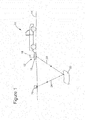
- a vehicle 10 tows a seismic source 12 from location to location.
- the seismic source 12 is placed on the ground 14 such that a plate 16 is in direct contact with the ground.
- a mechanism 18 is actuated to drive the plate 16 towards the ground 14 so that a seismic wave is generated.
- the seismic wave 20 propagates down into the Earth until it is reflected by a reflector 22.
- a reflected wave 24 is generated that propagates upward toward the surface 14 of the Earth.
- a sensor 26 may be deployed away from the vehicle 10 or next to the vehicle 10 to measure the reflected wave 24. Based on these measurements that are taken at various locations, a profile of the reflectors 22 is determined.
- the traditional seismic sources 12 need to be deployed by a vehicle 10 as they weigh too much to be portable. As the environmentally sensitive areas prohibit or strictly limit the access of heavy duty equipment or vehicles, the existing methods for generating seismic waves are not suitable for these areas. Alternatives sources for generating the seismic waves, e.g., explosives, may also be restricted in these areas. Thus, there is a need to develop a new seismic source that overcomes the above noted problems and drawbacks.
- a portable seismic source for generating seismic waves or energy in the ground.
- the portable seismic source includes an impact generator device configured to produce impulsive energy; a casing configured to house the impact generator device; a base plate configured to be placed on the ground; and a stabilizing foot mechanism configured to be provided between the casing and the base plate.
- the stabilizing foot mechanism includes a stabilizer which is fixed relative to the casing and configured to be placed on the base plate and a stanchion that is configured to move relative to the stabilizer when impacted by the impact generator device and to enter through the stabilizer and apply a force on the base plate.
- a portable seismic source for generating a seismic source underground.
- the portable seismic source includes a casing; a combustion chamber provided inside the casing; a piston provided inside the combustion chamber to divide the combustion chamber in a first chamber and a second chamber; compression means provided between the piston and a disk of the casing so that the piston is biased towards the first chamber; a base plate configured to be placed on the ground; and a stabilizing foot mechanism configured to be provided between the casing and the base plate.
- the piston is configured to prevent air from the second chamber moving into the first chamber through the piston and air from the first chamber moving into the second chamber through the piston.
- a method for generating a seismic wave includes injecting air and fuel in a combustion chamber; igniting the air and fuel to generate a high pressure in the combustion chamber; and displacing a piston provided inside the combustion chamber to transfer momentum to a base plate via a stanchion for generating the seismic wave.
- the piston divides the combustion chamber in first and second chambers and the piston is configured to prevent air from the second chamber moving into the first chamber through the piston and air from the first chamber moving into the second chamber through the piston.
- Figure 1 is a schematic diagram of a conventional land seismic source
- Figure 2 is a schematic diagram of a portable seismic source according to an exemplary embodiment
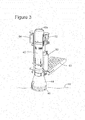
- Figure 3 is a schematic diagram of a portable seismic source having a platform according to an exemplary embodiment
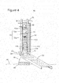
- Figure 4 is a schematic diagram of a portable seismic source according to another exemplary embodiment
- Figure 5 is a schematic diagram of various parts of a portable seismic source according to still another exemplary embodiment
- Figure 6 is a schematic diagram of a stabilizer mechanism of a seismic source according to an exemplary embodiment
- Figure 7 is a schematic diagram of a base plate and a stabilizer mechanism of a seismic source according to an exemplary embodiment
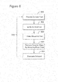
- Figure 8 is a flowchart illustrating a method for generating a seismic wave with a portable source according to an exemplary embodiment
- Figure 9 is a cross-view of a portable seismic source according to an exemplary embodiment.
- the novel seismic source does not use explosives.
- this novel seismic source complies with strict environmental requirements and can be transported by one or more persons to the desired location.
- the seismic source is a hammer that is activated by a fuel source, e.g., propane.
- a seismic source 40 includes a casing 42, a stabilizing foot mechanism 44 and a base plate 46.
- the casing 42 is configured to house an impact generator device which will be discussed later.
- the base plate 46 is configured to be placed in direct contact with the surface 48 of the Earth.
- the casing 42 includes a power source and a hammer mechanism (to be discussed later) that is configured to act on the base plate 46 for generating the seismic waves.
- the stabilizing foot mechanism 44 is configured to keep a predetermined distance between the casing 42 and the base plate 46.
- the stabilizing foot mechanism 44 is provided at a lower end of the casing 42 while an exhaust and intake valve (to be discussed later) are provided at a head or upper end 42a of the casing 42.
- FIG. 2 also shows the power source 50 that is attached to the seismic source 40 and configured to provide fuel to a combustion chamber.
- the power source 50 may be a gas tank, e.g., propane tank.
- the power source 50 may be, alternatively, a combustion source, a pneumatic source, a hydraulic source, an electrical source, etc.
- the impact generator device may be, alternatively, a device that generates an impact by combustion means, pneumatic means, hydraulic means, electrical means, etc.
- the power source 50 may be provided inside the casing 42.
- the fuel from the power source 50 is delivered by a gas delivery system 52 to the combustion chamber.
- a tank of compressed oxygen may be added and provided to the ignition chamber for increasing a power provided to the impact generator device.
- the fuel is mixed with air and/or the oxygen source as will be discussed later and ignited by an ignition control module 54.
- a platform 60 may be removably attached to the casing 42.
- the platform 60 may be made of metal (e.g., steel) and may have multiple purposes.
- One purpose is to provide a base for the operator of the seismic source 40 from where to control the source.
- Another purpose is to increase a weight of the seismic source 40 to counter balance a recoil that is produced in the casing 42 when the fuel is burnt in the combustion chamber and a momentum is transferred to the base plate 46 in a short amount of time.
- the platform 60 may be easily removed from the casing 42 and may be carried by another person than the person that carries the remainder of the seismic source 40.
- a weight of the seismic source 40 is between 50-100lbs and a weight of the platform 60 is in the range of 5-15lbs.
- the platform 60 is foldable, i.e., may be folded from the position shown in Figure 3 to a position in which a longitudinal axis of the platform is substantially parallel to a longitudinal axis of the casing 42.
- FIG. 4 A cut-through view of the seismic source 40 is shown in Figure 4 .
- This figure shows the platform 60 having two extensions 62 that connect to corresponding pins 64 attached to the casing 40.
- the platform 60 is not connected to the base plate 46.
- the extensions 62 have cuts that fit around the pins 64.
- the platform 60 is easily removable from the casing 42, i.e., no screws or other fixtures or tools are necessary.
- the casing 42 may be provided with a handle 70 for providing a point of stability to the operator that is on the platform 60 and operates the seismic source 40.
- a piston 74 is provided inside the casing 42 in which a piston 74 is provided. Piston 74 divides the combustion chamber 72 into a first chamber 72a and a second chamber 72b.
- Fuel is handled by the gas delivery system 52 (shown in Figures 2 and 3 ). The air/fuel is mixed in the first chamber 72a as discussed later.
- the gas delivery system 52 includes solenoid valves that are controlled by a microprocessor control circuit for opening and closing.
- FIG. 5 schematically shows the power source 50 connected to a pressure regulator 78 and a solenoid valve 80 that form the gas delivery system 52.
- the solenoid valve 80 is controlled by a processor 82 and is provided with an electrical current from a battery 84.
- the fuel is injected by nozzles 86 directly into the first chamber 72a.
- the air is provided via a valve 90 provided at a top of the casing 42.
- Valve 90 may be a solenoid valve and may be controlled to open and close by the processor 82.
- the processor can control the combustion mixture air/fuel ratio to optimize the combustion under varying conditions.
- an oxidizer tank 160 may be provided to supply an oxidizer fluid to the first chamber 72a for increasing the power produced by the ignition.
- the oxidizer fluid may be, for example, compressed oxygen. Similar to the power supply system, a pressure regulator 162, a solenoid valve 164 and a nozzle 166 may be used to control the flow of the oxidizer fluid into the first chamber 72a.
- the solenoid valve 164 may be connected to the battery 84 and also to the processor 82.
- Processor 82 may be part of a control module 92 that may also include a memory 94 for storing computer instructions.
- the computer instructions may be provided to the memory 94 via an interface 96.
- the interface 96 may include one or more of a port, keyboards, mouse, touch screen, etc.
- the control module 92 may be configured to operate the power source.
- control module 92 may be configured to compensate for ambient temperature, pressure, humidity, etc. Further, the control module 92 may be configured to control the impact generator device to perform a single impact, a plurality of impacts, a series of impacts with equal or unequal, predetermined time intervals, etc.
- the control module 92 may be controlled by the operator for choosing one or more of the modes discussed above. For example, a switch may be provided outside the casing 42 that selects one of the modes. Thus, the operator may simply select a desired mode by providing the switch in a corresponding position.
- the control module may also be configured to store (e.g., memory 94) information about one or more impacts. This information may be measured, for example, by one or more sensors (see 150 in Figure 6 ). These sensors may be provided in the base plate.
- the interface 96 of the control module 92 may be configured to connect to a cable for transferring information to and from an outside seismic recorder unit. In one application, the seismic recorder unit is far away from the seismic source 40. In this case, the interface 96 may include wireless communication means (e.g., a transceiver or a transmitter) for transmitting the data to and/or receiving information from the seismic recorder unit.
- both the nozzles 86 and the valve 90 are provided at the head 42a of the casing 42.
- Plural holes 98 are formed through the combustion chamber 72, in the second chamber 72a so that the exhaust from the burning process is released outside the combustion chamber.
- the ignition control module 54 is shown being connected to one or more spark plugs 100 that are in direct contact with an atmosphere inside first chamber 72a.
- the ignition control module 54 is also electrically linked to the processor 82.
- the processor 82 is able to control and coordinate the fuel supply, air intake, and the ignition of the mixture of air and fuel.
- the piston 74 is shown in contact with a first end of a compressible means 110.
- the compressible means 110 may be, for example, a spring.
- the compressible means 110 has a second end that contacts a starting mechanism 112.
- the starting mechanism 112 may include a disk 114 that contacts the second end of the compressible means 110.
- Disk 114 is a collar/ring on which the compressible means 110 sits. Disk 114 may be a collar that freely moves up and down and is constrained from travelling towards the ground by an internal stop, e.g., a snap ring.
- a top cap 130 goes through the disk 114 and is capable to move relative to the disk 114.
- the piston 74 is accelerated downwards compressing the compressible means 110 and ultimately directly contacting the top cap 130.
- a handle 116 the user can raise and lower the piston 74 to purge the combustion chamber 72a in the case of a misfire.
- the valve 90 needs to be open to permit this action.
- Disk 114 also acts as a 'stop' for the compressible means 110 to prevent it from getting pushed out the lower end of the chamber 42.
- the handle 116 is attached to the disk 114 and the handle 116 is provided outside the casing 42 so that the operator of the seismic source 40 may move the disk 114 up by means of slots (see Figures 2 , 3 an 4) in casing 42 to initiate the first upward stroke of the piston 74.
- the stabilizing foot mechanism 44 is interposed between disk 114 and base plate 46 as discussed next. As shown in Figure 6 , the stabilizing foot mechanism 44 is configured to stay on top of the base plate 46.
- a flexible material 120 e.g., rubber foam, may be inserted between the stabilizing foot mechanism 44 and the base plate 46. This flexible material suppresses most of the noises produced when hammering the stabilizing foot mechanism with piston 74. In other words, when piston 74 is actuated by the ignition of the fuel in the first chamber 72a, the piston 74 moves towards the stabilizing foot mechanism 44 and hits the top cap 130. Thus a more accurate seismic wave is generated by the base plate 46.
- the base plate 46 may be formed of aluminum and the flexible material 120 may be glued to the base plate 46.
- the stabilizing foot mechanism 44 includes the top cap 130 that is configured to interact with piston 74 as noted above.
- the top cap 130 may be made of stainless steel.
- the top cap 130 continues with a stanchion 132 that may be made of aluminum.
- the top cap 130 is fixedly attached to the stanchion 132.
- the stanchion 132 together with top cap 130 may freely move through the ring 114.
- the stanchion 132 is configured to enter a stabilizer 134 that may be made of aluminum.
- the stabilizer 134 is configured to be optionally attached to the casing 42. For example, screws may be inserted through the tail end of the casing 42 into holes 136 formed in a neck portion 138 of the stabilizer 134. Alternately, the weight of the operator standing on platform 60 can be employed to hold the casing 42 in contact with the stabilized 134.
- the stanchion 132 is configured to slide along direction Y relative to the stabilizer 134.
- a sleeve 140 may be provided inside the neck portion 138.
- the sleeve 140 may be made of Ultra-high-molecular-weight polyethylene (UHMW).
- UHMW Ultra-high-molecular-weight polyethylene
- the stanchion 132 is welded or attached by other means to the base plate 46.
- a skirt 146 may be provided between the base plate 46 and a bottom portion of the stabilizer 134. Other means may be used for keeping these elements together in a loose manner, as will be discussed later.
- the skirt 146 may be made of a textile material and it is attached by screws or bolts or pins 148a and 148b on both the base plate 46 and the bottom portion of the stabilizer 134. By being made of a textile material or other elastic material, the activation of the stanchion 132 and base plate 46 do not pull the casing 42 along the Y direction. The skirt 146 may be removed so that the base plate 46 can be detached from the stabilizer 134.
- the stabilizing foot mechanism 44 may also include, as shown in Figure 6 , a sensor 150 mounted to the base plate 46 for detecting an exact moment when the piston 74 strikes the base plate 46 and also to determine a 'source signature' - or force signature - of the signal that will be transferred to the ground. This could be accomplished by either one (1) or two (2) sensors.
- the sensor 150 may be electrically connected to the processor 82 shown in Figure 5 so that data may be recorded in the memory 94.
- step 800 fuel and air is provided in the first chamber 72a.
- the fuel intake is controlled by the solenoid valve 80 and the air intake is controlled by valve 90.
- the mixture of air and fuel is then ignited in step 802 by the ignition control module 54.
- the burning of the mixture in the first chamber 72a produces a sudden increase in pressure and thus, the piston 74 moves along the Y (vertical) direction with a predetermined force that is dictated by the size of the combustion chamber, the type of fuel, the amount of air, etc.
- the piston 74 by moving downwards, strikes in step 804 the top cap 130 of the stabilizing foot mechanism 44.
- the stanchion 132 by moving downward under the momentum from the top cap 130, forces the base plate 46 to be driven downwards on the ground and so produces a seismic wave in step 806.
- the exhaust produced by the burnt fuel is primarily evacuated from the combustion chamber through holes 98 in step 808.
- the exhaust is also evacuated when the piston 74 moves upwards, in the negative direction of the axis Y. This secondary evacuation takes place through the valve 90 and is coordinated by processor 82.
- Air is inserted into the chamber 72a through the valve 90 which acts as a dual purpose air/exhaust port.
- the intake of air may be naturally aspirated or a mechanism for achieving forced air to assist in the evacuation of exhaust from the chamber above 42a may be used. This mechanism may include the use of compressed air or a fan.
- step 810 the process is repeated for as long as the operator desires, or as programmed into the control circuit.
- the piston 74 does not have an internal valve and there is no mechanical means inside the first chamber 72a that is activated by piston 74 for allowing the air and/or fuel to enter the first chamber 72a.
- the platform 60 attaches to the casing 42 and not to the base plate 46.
- the seismic source 40 may be considered to act as a hammer, i.e., the piston 74 moves downwards to hit top cap 130 similar to a hammer hitting the head of a nail. This hammer action may be controlled by the operator to be continuous or in series, i.e., with a controlled time interval between two hammer actions. This interval is programmed into the control circuit.
- One or more of the exemplary embodiments discussed above advantageously provides a seismic source that exhibits a cycle time for 100 hits per 60 s, or maximizes an energy transfer between the piston, base plate and the ground, or improves a bandwidth of the signal to be about 75% of a typical hand drilled dynamite slot, or maintains a low weight so that the whole assembly may be carried by one or two persons, or eliminates secondary events.
- a weight of the whole assembly may be around 50 kg and an average cycle time may be about 600-1000 ms.
- FIG. 9 A cross-section view of a fully assembled portable seismic source 200 is illustrated in Figure 9 .
- the portable seismic source 200 includes the casing 42, the valve 90, the piston 74 that separates the first chamber 72a from the second chamber 72b, the compressible means 110, the disk 114, the top cap 130, the stanchion 132, the stabilizer 134, and the base plate 46.
- This portable seismic source 200 has a pin 210 that goes through the stanchion 132 and the ends 210a and 210b of the pin 210 ride up and down in slots 212 formed in the stabilizer 134.
- the base plate 46 does not need the skirt 146 shown in Figure 7 as the base plate 46 is now attached to the stanchion 132.
- the disclosed exemplary embodiments provide a portable system and a method for generating a seismic source that propagates underground. It should be understood that this description is not intended to limit the invention. On the contrary, the exemplary embodiments are intended to cover alternatives, modifications and equivalents, which are included in the spirit and scope of the invention as defined by the appended claims. Further, in the detailed description of the exemplary embodiments, numerous specific details are set forth in order to provide a comprehensive understanding of the claimed invention. However, one skilled in the art would understand that various embodiments may be practiced without such specific details.
Landscapes
- Engineering & Computer Science (AREA)
- Remote Sensing (AREA)
- Physics & Mathematics (AREA)
- General Physics & Mathematics (AREA)
- Life Sciences & Earth Sciences (AREA)
- Signal Processing (AREA)
- Computer Networks & Wireless Communication (AREA)
- Radar, Positioning & Navigation (AREA)
- General Life Sciences & Earth Sciences (AREA)
- Geophysics (AREA)
- Geology (AREA)
- Environmental & Geological Engineering (AREA)
- Acoustics & Sound (AREA)
- Mobile Radio Communication Systems (AREA)
- Geophysics And Detection Of Objects (AREA)
- Vibration Prevention Devices (AREA)
Applications Claiming Priority (1)
| Application Number | Priority Date | Filing Date | Title |
|---|---|---|---|
| US201161431963P | 2011-01-12 | 2011-01-12 |
Publications (2)
| Publication Number | Publication Date |
|---|---|
| EP2477045A2 true EP2477045A2 (de) | 2012-07-18 |
| EP2477045A3 EP2477045A3 (de) | 2015-04-29 |
Family
ID=45445962
Family Applications (1)
| Application Number | Title | Priority Date | Filing Date |
|---|---|---|---|
| EP20120150895 Withdrawn EP2477045A3 (de) | 2011-01-12 | 2012-01-12 | Tragbare Vorrichtung und Verfahren zur Erzeugung von seismischen Wellen |
Country Status (4)
| Country | Link |
|---|---|
| US (4) | US8855677B2 (de) |
| EP (1) | EP2477045A3 (de) |
| AU (1) | AU2012200182B2 (de) |
| CA (1) | CA2763973A1 (de) |
Families Citing this family (31)
| Publication number | Priority date | Publication date | Assignee | Title |
|---|---|---|---|---|
| US8855677B2 (en) * | 2011-01-12 | 2014-10-07 | Telefonaktiebolaget Lm Ericsson (Publ) | Nodes and methods for positioning |
| WO2014023999A1 (en) * | 2012-08-08 | 2014-02-13 | Nokia Siemens Networks Oy | Reactivating cells to improve positioning accuracy |
| US9693280B2 (en) | 2012-08-08 | 2017-06-27 | Nokia Solutions And Networks Oy | Interference reduction through cell activation methods in heterogeneous networks |
| US8838137B2 (en) * | 2012-08-30 | 2014-09-16 | Polaris Wireless, Inc. | Estimating the location of a wireless terminal in wireless telecommunications systems that comprise distributed and/or repeater antennas |
| US9521521B2 (en) | 2013-09-25 | 2016-12-13 | Gamesys Ltd. | Systems, methods, and apparatus for geolocation platform mechanics |
| CN104519567B (zh) * | 2013-09-26 | 2019-01-25 | 中国电信股份有限公司 | 基于服务交换机标识的定位方法和定位平台 |
| US10057719B2 (en) * | 2013-11-27 | 2018-08-21 | Alan Snyder | Methods and systems for locating persons and places with mobile devices |
| US9226114B2 (en) * | 2014-03-14 | 2015-12-29 | Hong Kong Applied Science And Technology Research Institute Co., Ltd. | Method and system of incorporating passive-based proximity data for position determination |
| EP3132592B1 (de) * | 2014-04-18 | 2018-02-21 | Telecom Italia S.p.A. | Verfahren und system zur identifizierung signifikanter standorte durch daten aus einem telekommunikationsnetz |
| US9398566B2 (en) * | 2014-09-18 | 2016-07-19 | Nokia Technologies Oy | Inter-operator radio resource sharing in dense deployments of small cell networks |
| US9942892B2 (en) * | 2014-09-30 | 2018-04-10 | The Boeing Company | Self-optimizing mobile satellite systems |
| US9906911B2 (en) | 2015-09-04 | 2018-02-27 | Telefonaktiebolaget L M Ericsson (Publ) | Systems and methods for UE positioning in a distributed antenna wireless system |
| JP2018526927A (ja) | 2015-09-04 | 2018-09-13 | テレフオンアクチーボラゲット エルエム エリクソン(パブル) | 共有セル環境におけるタイミングベースのue測位 |
| CN109477881A (zh) * | 2016-05-25 | 2019-03-15 | 弗劳恩霍夫应用研究促进协会 | 用于定位系统的波形设计 |
| EP3501209B1 (de) * | 2016-08-22 | 2021-04-14 | Telefonaktiebolaget LM Ericsson (publ) | Verarbeitungseinheit und verfahren darin zur initiierung der zellaktivierung |
| US10247837B2 (en) | 2017-02-27 | 2019-04-02 | Explor Geophysical Ltd. | Portable seismic survey device and method |
| US10104633B1 (en) * | 2017-03-31 | 2018-10-16 | Futurewei Technologies, Inc. | Active position driven mobility content delivery in information centric networks |
| US11334216B2 (en) * | 2017-05-30 | 2022-05-17 | Palantir Technologies Inc. | Systems and methods for visually presenting geospatial information |
| US10123297B1 (en) * | 2017-08-10 | 2018-11-06 | Lokatur, Inc. | System, method and devices for performing wireless tracking |
| CN108375787B (zh) * | 2018-03-02 | 2023-11-14 | 西南石油大学 | 一种用于气体钻井钻前探测的近钻头震源短节 |
| CN111886910B (zh) * | 2018-03-20 | 2021-10-26 | 华为技术有限公司 | 用于确定用户设备位置的本地实体、用户设备、接入网、全局实体、以及车辆 |
| US10394859B1 (en) | 2018-10-19 | 2019-08-27 | Palantir Technologies Inc. | Systems and methods for processing and displaying time-related geospatial data |
| US11175157B1 (en) | 2018-10-24 | 2021-11-16 | Palantir Technologies Inc. | Dynamic scaling of geospatial data on maps |
| US10771989B2 (en) | 2018-12-20 | 2020-09-08 | The Boeing Company | Adaptive self-optimizing network using closed-loop feedback |
| US11050616B2 (en) | 2018-12-20 | 2021-06-29 | The Boeing Company | Adaptive self-optimizing network using closed-loop feedback |
| US10805374B1 (en) | 2019-08-19 | 2020-10-13 | Palantir Technologies Inc. | Systems and methods for providing real-time streaming data processing at edge servers |
| US11765683B2 (en) * | 2020-04-20 | 2023-09-19 | Qualcomm Incorporated | Determining a user equipment position within a coverage sub-area of a cell based on cell identity data |
| CN111913212B (zh) * | 2020-09-08 | 2025-05-30 | 中国地质科学院地球物理地球化学勘查研究所 | 便携式横波激发装置 |
| US20240414685A1 (en) * | 2021-10-21 | 2024-12-12 | Telefonaktiebolaget Lm Ericsson (Publ) | Positioning measurement procedure under rrc state transition |
| US12085662B2 (en) | 2022-07-07 | 2024-09-10 | Nokia Solutions And Networks Oy | Radio map improvements |
| US20250159643A1 (en) * | 2023-11-09 | 2025-05-15 | Qualcomm Incorporated | Area information for positioning |
Family Cites Families (45)
| Publication number | Priority date | Publication date | Assignee | Title |
|---|---|---|---|---|
| US3306391A (en) * | 1964-03-16 | 1967-02-28 | Continental Oil Co | Portable seismic transducer |
| US3792752A (en) * | 1972-12-04 | 1974-02-19 | Western Geophysical Co | Portable seismic tool |
| US3957643A (en) * | 1974-08-12 | 1976-05-18 | Belz Frederick W | Centrifugal moisture extractor |
| US3912054A (en) * | 1974-11-25 | 1975-10-14 | Brian K Fabre | Valve replacement assembly for motorcycle front forks |
| US3997021A (en) * | 1975-05-16 | 1976-12-14 | Bolt Associates, Inc. | Pressurized gas discharging apparatus for use as a down-bore seismic impulse source |
| US4458777A (en) * | 1976-08-24 | 1984-07-10 | Texas Instruments Incorporated | Broadband seismic energy source |
| US4147228A (en) * | 1976-10-07 | 1979-04-03 | Hydroacoustics Inc. | Methods and apparatus for the generation and transmission of seismic signals |
| US4354572A (en) * | 1978-11-27 | 1982-10-19 | Mapco, Inc. | Portable seismic energy source |
| US4284164A (en) * | 1979-12-21 | 1981-08-18 | Atlantic Richfield Company | Acoustic pulse generator |
| US4421198A (en) * | 1980-09-04 | 1983-12-20 | Miller Norvel L | Variable frequency vacuum actuated seismic energy source |
| US4418786A (en) * | 1980-09-18 | 1983-12-06 | Mapco, Inc. | Bottom diaphragm for transporter for a seismic energy source |
| US4770269A (en) * | 1983-01-03 | 1988-09-13 | Atlantic Richfield Company | Closed air system seismic wave generator |
| US4691803A (en) * | 1985-11-18 | 1987-09-08 | Martin Philip N | Projectile powered piston |
| US4721181A (en) * | 1986-03-31 | 1988-01-26 | Atlantic Richfield Co. | Base plate locator for seismic source |
| US5005665A (en) * | 1986-06-16 | 1991-04-09 | The Standard Oil Company | Piezoelectric seismic vibration device and method |
| SU1509766A1 (ru) * | 1987-02-11 | 1989-09-23 | Всесоюзный Научно-Исследовательский И Проектно-Конструкторский Институт Взрывных Методов Геофизической Разведки | Источник сейсмических сигналов с регулируемыми амплитудно-частотными характеристиками |
| US4776562A (en) * | 1987-07-28 | 1988-10-11 | Stanley G. Flagg & Co. | Dual piston pneumatically operated valve |
| US4967870A (en) * | 1989-01-09 | 1990-11-06 | Atlantic Richfield Company | Alignment restoration means for use in seismic apparatus |
| US5018115A (en) * | 1989-01-23 | 1991-05-21 | Pascouet Adrien P | Marine acoustic source |
| US5189263A (en) * | 1990-07-12 | 1993-02-23 | Chevron Research And Technology Company | Human-portable geophysical energy source |
| US5347186A (en) * | 1992-05-26 | 1994-09-13 | Mcq Associates, Inc. | Linear motion electric power generator |
| US5416282A (en) * | 1994-04-22 | 1995-05-16 | King; John M. | Near-surface seismic investigation source apparatus |
| US5582557A (en) * | 1995-06-07 | 1996-12-10 | Titan Wheel International, Inc. | Hydraulically-operable locking differential with in-line piston means |
| US6244398B1 (en) * | 1997-05-15 | 2001-06-12 | K2 Bike Inc. | Shock absorber with variable bypass damping |
| US6026939A (en) * | 1997-05-15 | 2000-02-22 | K2 Bike Inc. | Shock absorber with stanchion mounted bypass damping |
| GB9928416D0 (en) * | 1999-12-01 | 2000-01-26 | Nokia Networks Oy | A telecommunications system |
| GB0008540D0 (en) * | 2000-04-06 | 2000-05-24 | Nokia Networks Oy | Provision of location service apparatus |
| US6536553B1 (en) * | 2000-04-25 | 2003-03-25 | The United States Of America As Represented By The Secretary Of The Army | Method and apparatus using acoustic sensor for sub-surface object detection and visualization |
| EP1320812A2 (de) * | 2000-06-14 | 2003-06-25 | Vermeer Manufacturing Company | Verfahren und system für die einteilung und verteilung der ortungsdaten von nutzeinrichtungen |
| US7321773B2 (en) * | 2002-03-28 | 2008-01-22 | Telecommunication Systems, Inc. | Area watcher for wireless network |
| US7284636B2 (en) * | 2004-02-03 | 2007-10-23 | United Service Alliance, Inc. | Accelerated weight drop for use as a seismic energy source and a method of operation thereof |
| US7139219B2 (en) * | 2004-02-12 | 2006-11-21 | Tempress Technologies, Inc. | Hydraulic impulse generator and frequency sweep mechanism for borehole applications |
| DE102004014722B3 (de) * | 2004-03-25 | 2005-12-29 | Geoforschungszentrum Potsdam | Seismische Quelle und Verfahren zur Erzeugung seismischer Schwingungen |
| US7489936B1 (en) * | 2004-10-14 | 2009-02-10 | Verizon Services Corp. | System and method for locating mobile terminals in mobile communication networks |
| US7706339B2 (en) * | 2005-08-10 | 2010-04-27 | Cisco Technology, Inc. | Method and system for communicating media based on location of media source |
| US20080021658A1 (en) * | 2006-06-10 | 2008-01-24 | Input/Output, Inc. | Apparatus and Method for Integrating Survey Parameters Into a Header |
| WO2008042799A2 (en) * | 2006-09-29 | 2008-04-10 | Ion Geophysical Corporation | System and apparatus for wireless seismic data acquisition |
| US8849183B2 (en) * | 2007-10-05 | 2014-09-30 | Qualcomm Incorporated | Location and time based filtering of broadcast information |
| ATE556298T1 (de) * | 2008-03-11 | 2012-05-15 | Gmv Aerospace And Defence S A | Verfahren zur darstellung der übereinstimmung mit gewährter integrität |
| US8125332B2 (en) * | 2008-11-21 | 2012-02-28 | Zoombak, Inc. | Geo-fence with minimal false alarms |
| US8125852B2 (en) * | 2009-05-25 | 2012-02-28 | Schlumberger Technology Corporation | Methods and systems for seismic signal detection |
| JP5153002B2 (ja) * | 2009-06-12 | 2013-02-27 | 株式会社エヌ・ティ・ティ・ドコモ | 移動通信方法、移動通信システム及び交換局 |
| US8855677B2 (en) * | 2011-01-12 | 2014-10-07 | Telefonaktiebolaget Lm Ericsson (Publ) | Nodes and methods for positioning |
| EP2673967B1 (de) * | 2011-02-10 | 2018-05-02 | Telefonaktiebolaget LM Ericsson (publ) | Verfahren und anordnungen in einem zellularen kommunikationssystem |
| US10168413B2 (en) * | 2011-03-25 | 2019-01-01 | T-Mobile Usa, Inc. | Service enhancements using near field communication |
-
2011
- 2011-04-27 US US13/266,937 patent/US8855677B2/en active Active
-
2012
- 2012-01-11 CA CA2763973A patent/CA2763973A1/en not_active Abandoned
- 2012-01-11 US US13/347,904 patent/US20120176863A1/en not_active Abandoned
- 2012-01-12 EP EP20120150895 patent/EP2477045A3/de not_active Withdrawn
- 2012-01-12 AU AU2012200182A patent/AU2012200182B2/en not_active Ceased
-
2013
- 2013-09-18 US US14/030,060 patent/US9049550B2/en active Active
-
2015
- 2015-06-01 US US14/727,098 patent/US9832750B2/en active Active
Non-Patent Citations (1)
| Title |
|---|
| None |
Also Published As
| Publication number | Publication date |
|---|---|
| US20150264660A1 (en) | 2015-09-17 |
| EP2477045A3 (de) | 2015-04-29 |
| US20120176863A1 (en) | 2012-07-12 |
| US9049550B2 (en) | 2015-06-02 |
| US9832750B2 (en) | 2017-11-28 |
| CA2763973A1 (en) | 2012-07-12 |
| AU2012200182A1 (en) | 2012-07-26 |
| AU2012200182B2 (en) | 2015-02-19 |
| US8855677B2 (en) | 2014-10-07 |
| US20140018103A1 (en) | 2014-01-16 |
| US20120178473A1 (en) | 2012-07-12 |
Similar Documents
| Publication | Publication Date | Title |
|---|---|---|
| AU2012200182B2 (en) | Portable device and method to generate seismic waves | |
| US7926690B1 (en) | Combustion powered driver | |
| US8371416B2 (en) | Constant holddown weight for vibratory seismic sources | |
| US7775305B1 (en) | Wheeled hopping robot | |
| US8261874B2 (en) | Attenuating out of band energy emitted from seismic sources | |
| US4324310A (en) | Seismic apparatus | |
| CA1082349A (en) | Fast cycle seismic gas exploder and method | |
| CA2504119A1 (en) | An accelerated weight drop configurable for use as a shear wave seismic energy source and a method of operation thereof | |
| CN114460627A (zh) | 一种气动冲击震源 | |
| US6966478B2 (en) | Combustion apparatus having collapsible volume | |
| US4007803A (en) | Expanding detonation chamber multi-shot gas exploder | |
| US3958661A (en) | Method and apparatus for generating seismic waves | |
| Lugg | Marine seismic sources | |
| WO2003042717A1 (en) | Seismic wave generator | |
| US3382946A (en) | Liquid seismic explosive and method of using | |
| US7284636B2 (en) | Accelerated weight drop for use as a seismic energy source and a method of operation thereof | |
| EP1606081B1 (de) | Gasdruckvorrichtungen mit einem vorkompressionsraum und einer brennkammer | |
| US7918307B2 (en) | Accelerated weight drop for use as a seismic energy source and a method of operation thereof | |
| US3416621A (en) | Acoustic wave producing device | |
| US4102429A (en) | Apparatus for generating seismic waves | |
| US3901351A (en) | Carrier for seismic exploder | |
| CN210570249U (zh) | 一种模拟战场爆炸火焰效果的气体爆炸装置 | |
| AU2008203842A1 (en) | Combustion powered driver | |
| CN115097515B (zh) | 一种浅层地震法震源激发装置 | |
| JPS63165790A (ja) | 音波発生装置 |
Legal Events
| Date | Code | Title | Description |
|---|---|---|---|
| PUAI | Public reference made under article 153(3) epc to a published international application that has entered the european phase |
Free format text: ORIGINAL CODE: 0009012 |
|
| AK | Designated contracting states |
Kind code of ref document: A2 Designated state(s): AL AT BE BG CH CY CZ DE DK EE ES FI FR GB GR HR HU IE IS IT LI LT LU LV MC MK MT NL NO PL PT RO RS SE SI SK SM TR |
|
| AX | Request for extension of the european patent |
Extension state: BA ME |
|
| RIC1 | Information provided on ipc code assigned before grant |
Ipc: G01V 1/147 20060101AFI20141127BHEP |
|
| PUAL | Search report despatched |
Free format text: ORIGINAL CODE: 0009013 |
|
| AK | Designated contracting states |
Kind code of ref document: A3 Designated state(s): AL AT BE BG CH CY CZ DE DK EE ES FI FR GB GR HR HU IE IS IT LI LT LU LV MC MK MT NL NO PL PT RO RS SE SI SK SM TR |
|
| AX | Request for extension of the european patent |
Extension state: BA ME |
|
| RIC1 | Information provided on ipc code assigned before grant |
Ipc: G01V 1/147 20060101AFI20150325BHEP |
|
| RAP1 | Party data changed (applicant data changed or rights of an application transferred) |
Owner name: CGG SERVICES SA |
|
| 17P | Request for examination filed |
Effective date: 20151008 |
|
| RBV | Designated contracting states (corrected) |
Designated state(s): AL AT BE BG CH CY CZ DE DK EE ES FI FR GB GR HR HU IE IS IT LI LT LU LV MC MK MT NL NO PL PT RO RS SE SI SK SM TR |
|
| STAA | Information on the status of an ep patent application or granted ep patent |
Free format text: STATUS: THE APPLICATION IS DEEMED TO BE WITHDRAWN |
|
| 18D | Application deemed to be withdrawn |
Effective date: 20180801 |