EP2477920B1 - Wartungsfreundliche multifunktions-pitch-änderungsvorrichtung - Google Patents
Wartungsfreundliche multifunktions-pitch-änderungsvorrichtung Download PDFInfo
- Publication number
- EP2477920B1 EP2477920B1 EP10817587.8A EP10817587A EP2477920B1 EP 2477920 B1 EP2477920 B1 EP 2477920B1 EP 10817587 A EP10817587 A EP 10817587A EP 2477920 B1 EP2477920 B1 EP 2477920B1
- Authority
- EP
- European Patent Office
- Prior art keywords
- stream
- base
- pitch changing
- recited
- printing press
- Prior art date
- Legal status (The legal status is an assumption and is not a legal conclusion. Google has not performed a legal analysis and makes no representation as to the accuracy of the status listed.)
- Not-in-force
Links
- 238000012423 maintenance Methods 0.000 title claims description 11
- 238000000034 method Methods 0.000 claims description 5
- 230000001419 dependent effect Effects 0.000 claims 3
- 235000011868 grain product Nutrition 0.000 description 6
- 230000008901 benefit Effects 0.000 description 3
- 235000013339 cereals Nutrition 0.000 description 3
- 230000007257 malfunction Effects 0.000 description 3
- 230000008439 repair process Effects 0.000 description 3
- 238000003197 gene knockdown Methods 0.000 description 2
- 230000007246 mechanism Effects 0.000 description 2
- 230000000284 resting effect Effects 0.000 description 2
- 230000008859 change Effects 0.000 description 1
- 238000013461 design Methods 0.000 description 1
- 230000009977 dual effect Effects 0.000 description 1
- 230000003993 interaction Effects 0.000 description 1
- 238000012986 modification Methods 0.000 description 1
- 230000004048 modification Effects 0.000 description 1
- 230000035945 sensitivity Effects 0.000 description 1
- 238000006467 substitution reaction Methods 0.000 description 1
- 238000013519 translation Methods 0.000 description 1
- 238000011144 upstream manufacturing Methods 0.000 description 1
Images




Classifications
-
- B—PERFORMING OPERATIONS; TRANSPORTING
- B41—PRINTING; LINING MACHINES; TYPEWRITERS; STAMPS
- B41F—PRINTING MACHINES OR PRESSES
- B41F13/00—Common details of rotary presses or machines
- B41F13/54—Auxiliary folding, cutting, collecting or depositing of sheets or webs
-
- B—PERFORMING OPERATIONS; TRANSPORTING
- B65—CONVEYING; PACKING; STORING; HANDLING THIN OR FILAMENTARY MATERIAL
- B65H—HANDLING THIN OR FILAMENTARY MATERIAL, e.g. SHEETS, WEBS, CABLES
- B65H29/00—Delivering or advancing articles from machines; Advancing articles to or into piles
- B65H29/12—Delivering or advancing articles from machines; Advancing articles to or into piles by means of the nip between two, or between two sets of, moving tapes or bands or rollers
- B65H29/125—Delivering or advancing articles from machines; Advancing articles to or into piles by means of the nip between two, or between two sets of, moving tapes or bands or rollers between two sets of rollers
-
- B—PERFORMING OPERATIONS; TRANSPORTING
- B65—CONVEYING; PACKING; STORING; HANDLING THIN OR FILAMENTARY MATERIAL
- B65H—HANDLING THIN OR FILAMENTARY MATERIAL, e.g. SHEETS, WEBS, CABLES
- B65H2301/00—Handling processes for sheets or webs
- B65H2301/40—Type of handling process
- B65H2301/44—Moving, forwarding, guiding material
- B65H2301/445—Moving, forwarding, guiding material stream of articles separated from each other
- B65H2301/4452—Regulating space between separated articles
- B65H2301/44522—Varying space between separated articles
-
- B—PERFORMING OPERATIONS; TRANSPORTING
- B65—CONVEYING; PACKING; STORING; HANDLING THIN OR FILAMENTARY MATERIAL
- B65H—HANDLING THIN OR FILAMENTARY MATERIAL, e.g. SHEETS, WEBS, CABLES
- B65H2402/00—Constructional details of the handling apparatus
- B65H2402/10—Modular constructions, e.g. using preformed elements or profiles
-
- B—PERFORMING OPERATIONS; TRANSPORTING
- B65—CONVEYING; PACKING; STORING; HANDLING THIN OR FILAMENTARY MATERIAL
- B65H—HANDLING THIN OR FILAMENTARY MATERIAL, e.g. SHEETS, WEBS, CABLES
- B65H2402/00—Constructional details of the handling apparatus
- B65H2402/30—Supports; Subassemblies; Mountings thereof
- B65H2402/32—Sliding support means
-
- B—PERFORMING OPERATIONS; TRANSPORTING
- B65—CONVEYING; PACKING; STORING; HANDLING THIN OR FILAMENTARY MATERIAL
- B65H—HANDLING THIN OR FILAMENTARY MATERIAL, e.g. SHEETS, WEBS, CABLES
- B65H2402/00—Constructional details of the handling apparatus
- B65H2402/40—Details of frames, housings or mountings of the whole handling apparatus
-
- B—PERFORMING OPERATIONS; TRANSPORTING
- B65—CONVEYING; PACKING; STORING; HANDLING THIN OR FILAMENTARY MATERIAL
- B65H—HANDLING THIN OR FILAMENTARY MATERIAL, e.g. SHEETS, WEBS, CABLES
- B65H2601/00—Problem to be solved or advantage achieved
- B65H2601/30—Facilitating or easing
- B65H2601/32—Facilitating or easing entities relating to handling machine
-
- B—PERFORMING OPERATIONS; TRANSPORTING
- B65—CONVEYING; PACKING; STORING; HANDLING THIN OR FILAMENTARY MATERIAL
- B65H—HANDLING THIN OR FILAMENTARY MATERIAL, e.g. SHEETS, WEBS, CABLES
- B65H2601/00—Problem to be solved or advantage achieved
- B65H2601/30—Facilitating or easing
- B65H2601/32—Facilitating or easing entities relating to handling machine
- B65H2601/324—Removability or inter-changeability of machine parts, e.g. for maintenance
-
- B—PERFORMING OPERATIONS; TRANSPORTING
- B65—CONVEYING; PACKING; STORING; HANDLING THIN OR FILAMENTARY MATERIAL
- B65H—HANDLING THIN OR FILAMENTARY MATERIAL, e.g. SHEETS, WEBS, CABLES
- B65H2601/00—Problem to be solved or advantage achieved
- B65H2601/30—Facilitating or easing
- B65H2601/32—Facilitating or easing entities relating to handling machine
- B65H2601/326—Manual handling of handling machine
-
- B—PERFORMING OPERATIONS; TRANSPORTING
- B65—CONVEYING; PACKING; STORING; HANDLING THIN OR FILAMENTARY MATERIAL
- B65H—HANDLING THIN OR FILAMENTARY MATERIAL, e.g. SHEETS, WEBS, CABLES
- B65H2801/00—Application field
- B65H2801/03—Image reproduction devices
- B65H2801/21—Industrial-size printers, e.g. rotary printing press
Definitions
- the present invention relates generally to printing presses and more particularly to conveyors altering the pitch of printed products printed in the printing press.
- the invention relates to a printing press according to the preamble of claim 1. Such a press is known from EP1279632 .
- US2004/145108 and DE102005020591 disclose further handling devices for printed products.
- U.S. Patent No. 6,176,485 discloses a diverting device for a continuous sequence of flat products traveling in a product travel plane. A first product exit path and a second product exit path emerge both from said product travel plane.
- U.S. Patent No. 6,405,850 discloses an apparatus for advancing and/or slowing signatures in a printing press.
- the apparatus and method includes a series of two or more belt drives, where each belt drive includes at least a pair of opposed belts.
- the belts are preferably timing or toothed belts driven by sprockets.
- U.S. Patent No. 6,561,507 discloses a folder apparatus that includes a conveyor and knock-down wheel assembly to receive signatures from, for example, a tape system output.
- the conveyor and knock-down wheel assembly slow down the signatures from the tape system and create a shingled output stream of signatures.
- U.S. Patent Application Publication 2009/0217833 discloses an electronic pitch changing apparatus for altering the pitch of printed products.
- the electronic pitch changing apparatus includes a motor having a variable velocity profile.
- the present invention provides a printing press according to claim 1.
- the printing press includes inter alia a print unit printing a plurality of printed products, the plurality of printed products being formed into a stream downstream of the print unit, the printed product stream having a first pitch.
- the printing press also includes at least one base and a pitch changing device for changing the first pitch of the stream, the pitch changing device is mounted onto the at least one base for placement in the stream and translational movement transverse to the stream.
- the present invention also provides a method according to claim 14.
- the method includes the step of translating a pitch changing device transverse to a stream to place the device in the stream or to remove the device from the stream.
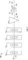
- Fig. 1 shows a preferred embodiment of a web printing press 100 in accordance with the present invention including a web 101 traveling through a plurality of printing units 112 and a folder 120 providing a plurality of signatures 102, 104 to a printing press component or module, for example, an electronic pitch changing apparatus 10.
- Printing units 112 print an image on web 101.
- Printing units 112 maybe web, offset, perfecting printing units.
- Each print unit 112 may print a different color, for example, cyan, magenta, yellow or black.
- Folder 120 may include a former board for longitudinally folding a web 101 and/or folder 120 may fold and/or cut web 101 into signatures 102, 104.
- Signatures have a first pitch, P 1 , before entering electronic pitch changing apparatus 10 and a second pitch P 2 after exiting pitch changing apparatus 10.
- Electronic pitch changing apparatus 10 alters first pitch P 1 so downstream signatures 102', 104' have a second pitch P 2 , in this example, P 2 is less than P 1 so signatures 102', 104' are closer together than upstream signatures 102, 104.
- Electronic pitch changing apparatus 10 may also be a slowdown device slowing down the speed of signatures 102', 104'.
- Electronic pitch changing apparatus 10 may be similar to the electronic pitch changing apparatus disclosed in U.S. Patent Application Publication 2009/0217833 .
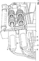
- Fig. 2 shows a preferred embodiment of electronic pitch changing apparatus 10.
- Electronic pitch changing apparatus 10 includes rollers 20, 24 mounted on axle 62 and rollers 22, 26 mounted on axle 64.
- Roller 20 and roller 22 create a continuous nip 40 and roller 24 and roller 26 create a continuous nip 42.
- Edge sensors 50 are connected to controller 30 and detect a leading edge of products 104, 102 entering nips 40, 42.
- Axle 62 rotates in a clockwise direction while axle 64 rotates in a counter-clockwise direction.
- a motor 60 drives axle 64 directly and a motor 61 drives axle 62 directly. Motors 60, 61 are connected to controller 30.
- Electronic pitch changing apparatus 10 works to vary a first pitch P 1 between products 104, 102.
- Edge sensor 50 will detect the leading edge of products 104, 102 entering nips 40, 42.
- Controller 30 keeps electronic cam profiles of motors 60, 61 accurately in phase with products 104, 102 to vary initial pitch P 1 to a final pitch P 2 between products 104' and 102'. Controller 30 automates the initial timing and may reduce interaction and confusion for an operator.
- the cam profile may be sinusoidal, symmetric or asymmetric. Cam profiles of individual motors do not have to be identical when a diverter or stream separator is used.
- Electronic pitch changing apparatus 10 advantageously may be used on all folder cutoff lengths since the length of the nips does not need to be resized. Continuous nips advantageously provide flexibility since as little or as much of the nip surface may be used as desired.
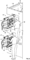
- Figs. 3 and 4 show an electronic pitch changing apparatus 10 mounted on a base 80 in accordance with the present embodiment.
- Base 80 includes a pair of slide rails 86.
- An actuator for example, pneumatic air cylinder 32 is used to move electronic pitch changing apparatus 10 from a position between frame sidewalls 16, 16' ( Fig. 6 ) to a maintenance position adjacent sidewall 16' along slide rails 86 ( Fig. 6 ).
- Pneumatic flow controls are provided to adjust the speed electronic pitch changing apparatus 10 moves.
- a safety device may need to be in place before movement along slide rails 86 is permitted. Manual movement may also be possible.
- another type of press component or module for example, a ribbon stitcher, may be mounted onto base 80 for similar translation movement into and out of the product stream or into and out of a position between frame sidewalls 16, 16'.
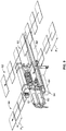
- Figs. 5 to 7 show two electronic pitch changing apparatus 10, 10', upper and lower, respectively, mounted on bases 80, 80' in accordance with the present embodiment for use in a two-story printing press.
- Electronic pitch changing apparatus 10, 10' are shown resting in a maintenance position outside of frame 116.
- Frame may be a folder frame or a printing press frame.
- Frame 116 includes two sidewalls 16, 16'.
- Each electronic pitch changing apparatus 10, 10' is movably mounted on base 80, 80'.
- each base 80, 80' includes an internal base 82, 82', an external base 84, 84' and two slide rails 86, 86'.
- Internal base 82, 82' may be fixed between frame sidewalls 16, 16'.
- External base 84, 84' maybe cantilevered to a side of the frame, for example, sidewall 16'.
- Slide rails 86, 86' extend from sidewall 16 across internal base 82, 82' through an opening in sidewall 16' and continue across to an end of external base 84, 84'.
- internal base 82 and external base 84 may be designed as a single base component.
- base 80 may be designed to fully cantilever electronic pitch changing apparatus in between frame sidewalls 16, 16'.
- base 80 may have a fixed portion and a movable portion.
- Electronic pitch changing apparatus 10, 10' are able to slide along slide rails 86, 86' into a press operating position between frame sidewalls 16, 16' to a maintenance position outside of frame 116 adjacent sidewall 16' (shown) via pneumatic air cylinder 32 ( Fig. 4 ). In the maintenance position, operators 88, 88' may easily access electronic pitch changing apparatus 10, 10' for repairs, replacement or substitution.
- the electronic pitch changing apparatus 10, 10' may be removed from base 80, 80' by moving electronic pitch changing apparatus 10, 10' from the press operating position to the maintenance position and subsequently removing electronic pitch changing apparatus 10, 10' from slide rails 86, 86'.
- a replacement electronic pitch changing apparatus may be mounted to slide rails 86, 86' and slid into the press operating position between frame sidewalls 16, 16' so the press may continue to run, thereby reducing press downtime during a malfunction.
- Fig. 8 shows another preferred embodiment of electronic pitch changing apparatus 10 being used alternately on two separate printed product streams.
- internal base 82 extends across a length transverse to a long grain product stream 94 and a short grain product stream 92.
- electronic pitch changing apparatus 10 may operate on a stream 94 or be moved into a second operating position and operate on stream 92.
- Electronic pitch changing apparatus 10 may be easily and quickly moved into stream 92 or into stream 94 by sliding electronic pitch changing apparatus over slide rails 86 of base 80.
- Electronic velocity profiles of motors 60, 61 may be quickly changing software via controller 30.
- electronic pitch changing apparatus 10 may be easily integrated into two different product streams having products with different cutoffs.
- Fig. 9 shows another preferred embodiment of electronic pitch changing apparatus 10 operating on one of two simultaneous printed product streams.
- internal base 82 extends across a length transverse to a long grain product stream 94 and a short grain product stream 92.
- Electronic pitch changing apparatus 10 is setup to reduce the first pitch P 1 of products in long grain product stream 94 to a smaller pitch P 2 while products in short grain product stream 92 are unaltered by electronic pitch changing apparatus 10.
- Products in product stream 92 are conveyed over internal base 82 further downstream.
- Electronic pitch changing apparatus 10 mounted on base 80 provides many advantages. For example, an advantage may include the ability to move electronic pitch changing apparatus 10 from an existing press 100 ( Fig. 1 ) to an alternative press. Since electronic pitch changing apparatus 10 works on a variety of cutoffs, electronic pitch changing apparatus 10 can be placed in an alternative press running the same cutoff or running a different cutoff. A change in software controlling the velocity profile for motors 60, 61 may also be required.
- Another advantage may include the ability to easily replace a broken or malfunctioning electronic pitch changing apparatus 10 with a replacement electronic pitch changing apparatus in order to reduce press downtime and continue printing with minimum disruption.
- an alternative printing press component or module may be used to replace electronic pitch changing apparatus 10, for example, a ribbon stitcher.
- a drive system including motors 60, 61 may be left in place.
- Electronic pitch changing apparatus 10 may be disconnected from motors 60, 61 and a ribbon stitcher may be connected to motors 60, 61 so ribbon stitcher may be easily integrated into the existing printing press setup.
- a velocity profile for the motors may be modified as necessary.
- the present invention advantageously eliminates the use of tapes in a pitch changing apparatus and advantageously improves accessibility of the pitch changing apparatus for maintenance thereby reducing machine downtime during repair, malfunction or routine maintenance.
- the present invention advantageously satisfies the need for a pitch changing device that can work on multiple cutoffs and multiple product streams with ease and with a cost savings.
- the present invention advantageously provides a pitch changing device that can be used in any printing press regardless of product cutoff and advantageously increases the ease of assembling, maintaining and adjusting the pitch changing device. Sensitivity to jamming may also be reduced.
- the operator By translating the pitch changing device outside of the machine for maintenance and adjustments the operator has easy access to the entire assembly. This allows the operator to make quick adjustments with minimal effort and impedance form other parts of the machine.
- the present invention also makes replacement of the entire assembly easily achievable by simply sliding the exciting device completely off the guide rails and replacing it with a new or rebuilt one. Since there are no tapes running through the device, collateral damage to the device from tape failure is also significantly reduced.
- An added feature of this invention is its dual usage capability. In a folder that has side by side fold cylinders of different cutoffs or grain orientations (short grain v. long grain) this device could be shared by both product streams.
- the present invention may also be removed from one machine and placed into a different machine to either do a similar function with the same cutoff or be used for a different function or different cutoff by changing software to adjust the motors.
- the mechanical drive module could be reused with different press components or modules, such as replacing the pitch changing mechanism with a ribbon stitching mechanism and different control software.
- Ribbon stitchers are typically cutoff specific by design, whereas this invention would allow use of a common stitcher on different cutoff machines, or variable cutoff machines.
Landscapes
- Engineering & Computer Science (AREA)
- Mechanical Engineering (AREA)
- Inking, Control Or Cleaning Of Printing Machines (AREA)
Claims (15)
- Druckpresse, umfassend:- eine Druckeinheit (112), die eine Vielzahl von gedruckten Produkten druckt, wobei die Vielzahl von gedruckten Produkten zu einem Strom nachgeordnet von der Druckeinheit gebildet ist;- mindestens eine Basis (80, 80'); und- eine Pressenkomponente, wobei die Pressenkomponente auf die mindestens eine Basis für translatorische Bewegung quer zum Strom montiert ist,- der Strom aus gedruckten Produkten einen ersten Abstand aufweist,dadurch gekennzeichnet, dass
die Pressenkomponente (10, 10') auf die mindestens eine Basis zur Anbringung im Strom montiert ist, dass
die Pressenkomponente eine Abstandsänderungsvorrichtung (10, 10') zum Ändern der ersten Abstand des Stroms ist, und dass
sich der Strom zwischen zwei Seitenwänden (16, 16') befindet und die Abstandsänderungsvorrichtung (10, 10') aus einer Position in der Nähe einer Seitenwand in eine Position zwischen den zwei Seitenwänden bewegt wird. - Druckpresse nach Anspruch 1, wobei die Abstandsänderungsvorrichtung von der mindestens einen Basis entfernt werden kann.
- Druckpresse nach einem der Ansprüche 1 oder 2, wobei die Abstandsänderungsvorrichtung beweglich auf die mindestens eine Basis (80, 80') montiert ist, wobei die Presse weiter einen weiteren Strom von gedruckten Produkten umfasst und die Abstandsänderungsvorrichtung beweglich auf die mindestens eine Basis zur Anbringung in dem weiteren Strom und translatorischen Bewegung quer zum weiteren Strom montiert ist.
- Druckpresse nach einem der Ansprüche 1 bis 3, wobei die mindestens eine Basis (80, 80') eine interne Basis (82, 82'), eine externe Basis (84, 84') und Gleitschienen (86, 86') umfasst.
- Druckpressee nach einem der Ansprüche 1 bis 4, weiter umfassend einen Rahmen (116), der einen Abschnitt der/des mindestens einen Basis oder Stroms umgibt, um eine Betriebsposition und eine Wartungsposition zu definieren.
- Druckpresse nach einem der Ansprüche 1 bis 5, weiter umfassend eine weitere Abstandsänderungsvorrichtung, die auf die mindestens eine Basis (80, 80') montiert werden kann, nachdem die Abstandsänderungsvorrichtung von der mindestens einer Basis entfernt ist.
- Druckpresse nach einem der Ansprüche 1 bis 6, weiter umfassend einen Aktuator (32), um die Abstandsänderungsvorrichtung entlang der mindestens einen Basis zu gleiten, wobei vorzugsweise der Aktuator ein pneumatischer Luftzylinder (32) ist.
- Druckpresse nach Anspruch 5 oder einem Anspruch, der von Anspruch 5 abhängt, wobei sich mindestens ein Abschnitt der mindestens einen Basis in den Strom zwischen den zwei Seitenwänden erstreckt.
- Druckpresse nach Anspruch 5 oder einem Anspruch, der von Anspruch 5 abhängt, wobei der mindestens eine Abschnitt der Basis eine Seitenschiene (86, 86') ist.
- Druckpresse nach einem der Ansprüche 1 bis 9, wobei sich die Abstandsänderungsvorrichtung mit Bezug auf die Basis (80, 80') bewegt.
- Druckpresse nach einem der Ansprüche 1 bis 10, weiter umfassend eine Steuervorrichtung (30).
- Druckpresse nach einem der Ansprüche 1 bis 11, wobei die Abstandsänderungsvorrichtung weiter eine Vielzahl von Motoren (60, 61) umfasst.
- Druckpresse nach Anspruch 3 oder einem Anspruch, der von Anspruch 3 abhängt, wobei die Presse weiter einen weiteren Strom von gedruckten Produkten umfasst und die Abstandsänderungsvorrichtung auf die mindestens eine Basis zur Anbringung im weiteren Strom und translatorischen Bewegung quer zum weiteren Strom montiert ist, wobei der weitere Strom aus Produkten (94) Produkte umfasst, die einen verschiedenem Cutoff als gedruckte Produkt im Strom (92) aufweisen.
- Verfahren, umfassend die folgenden Schritte:Übertragen einer Abstandsänderungsvorrichtung einer Druckpresse nach Anspruch 1 quer zu einem Strom, um die Vorrichtung im Strom anzubringen oder die Vorrichtung vom Strom zu entfernen.
- Verfahren nach Anspruch 14, wobei der Schritt des Übertragens das Bewegen der Abstandsänderungsvorrichtung entlang einer Seitenschiene (86, 86') umfasst.
Applications Claiming Priority (2)
| Application Number | Priority Date | Filing Date | Title |
|---|---|---|---|
| US24372709P | 2009-09-18 | 2009-09-18 | |
| PCT/US2010/002566 WO2011034618A1 (en) | 2009-09-18 | 2010-09-20 | A multi-functional maintenance friendly pitch-changing apparatus |
Publications (3)
| Publication Number | Publication Date |
|---|---|
| EP2477920A1 EP2477920A1 (de) | 2012-07-25 |
| EP2477920A4 EP2477920A4 (de) | 2014-09-17 |
| EP2477920B1 true EP2477920B1 (de) | 2017-02-15 |
Family
ID=43755510
Family Applications (1)
| Application Number | Title | Priority Date | Filing Date |
|---|---|---|---|
| EP10817587.8A Not-in-force EP2477920B1 (de) | 2009-09-18 | 2010-09-20 | Wartungsfreundliche multifunktions-pitch-änderungsvorrichtung |
Country Status (3)
| Country | Link |
|---|---|
| US (1) | US20110067587A1 (de) |
| EP (1) | EP2477920B1 (de) |
| WO (1) | WO2011034618A1 (de) |
Family Cites Families (11)
| Publication number | Priority date | Publication date | Assignee | Title |
|---|---|---|---|---|
| US4451027A (en) * | 1980-01-09 | 1984-05-29 | Burroughs Corp. | Constant spacing document feeder |
| JPH051398Y2 (de) * | 1987-11-06 | 1993-01-14 | ||
| US5322270A (en) * | 1991-07-16 | 1994-06-21 | Heidelberg-Harris Gmbh | Delivery systems in the folder of a web-fed rotary printing machine |
| SE507816C2 (sv) * | 1994-02-09 | 1998-07-20 | Tetra Laval Holdings & Finance | Rotationstryckpress uppbyggd kring ett balkverk från vilket tryckverket hänger ned |
| FR2814839B1 (fr) * | 2000-09-29 | 2003-02-28 | Neopost Ind | Machine a affranchir polyvalente |
| CA2347562A1 (en) * | 2001-05-14 | 2002-11-14 | John Lovaghy | Device for aligning papers flowing in a stream |
| US6533268B2 (en) * | 2001-07-27 | 2003-03-18 | Xerox Corporation | Printer sheet lateral registration and deskewing system |
| US6644660B2 (en) * | 2001-10-26 | 2003-11-11 | Pitney Bowes Inc. | Dynamic pitch correction for an output inserter subsystem |
| US6880818B2 (en) * | 2003-01-24 | 2005-04-19 | Edward Desaulniers | Flyless stream shingling and stream merging apparatus and method |
| DE102005020591C5 (de) * | 2005-05-03 | 2009-11-05 | Rolf Pitzen | Basisvorrichtung einer Anlage zur Weiterverarbeitung von Druckerzeugnissen |
| US20090217833A1 (en) * | 2008-02-29 | 2009-09-03 | Goss International Americas, Inc. | Conveyor and method for changing the pitch of printed products |
-
2010
- 2010-09-20 EP EP10817587.8A patent/EP2477920B1/de not_active Not-in-force
- 2010-09-20 US US12/924,061 patent/US20110067587A1/en not_active Abandoned
- 2010-09-20 WO PCT/US2010/002566 patent/WO2011034618A1/en not_active Ceased
Non-Patent Citations (1)
| Title |
|---|
| None * |
Also Published As
| Publication number | Publication date |
|---|---|
| EP2477920A1 (de) | 2012-07-25 |
| US20110067587A1 (en) | 2011-03-24 |
| WO2011034618A1 (en) | 2011-03-24 |
| EP2477920A4 (de) | 2014-09-17 |
Similar Documents
| Publication | Publication Date | Title |
|---|---|---|
| CN106541715B (zh) | 避免碰撞、适配间距及执行器致动式行程运动用的方法 | |
| EP2393740B1 (de) | Netzumwandlungsvorrichtung und -verfahren mit einstellbarer ausgabe | |
| US6422552B1 (en) | Movable folders and former board arrangement | |
| US11597200B2 (en) | Sheet processing machine, method for inspecting at least one remaining portion of at least one sheet processed by a shaping device, and method for inspecting a sheet | |
| US12612273B2 (en) | Inversion transfer module for a converting machine | |
| EP2247519B1 (de) | Förderer und verfahren zur pitch-änderung bei druckerzeugnissen | |
| US20120111163A1 (en) | Variable Folding System Comprising Linear Drives, Especially For Printing Machines | |
| CA2764122A1 (en) | Book block finishing machine | |
| US8196926B2 (en) | Apparatus for electronically diverting signatures | |
| EP2287098B1 (de) | Papierblattförderer und papierblattfördersystem | |
| EP2055657A2 (de) | Verfahren zum Steuern der Zufuhr von Bogen zu einer Bogendruckmaschine | |
| JP5918917B1 (ja) | オフセット輪転印刷機及びオフセット輪転印刷機の印刷制御方法 | |
| JP2011178565A (ja) | シートガイド装置、シートガイド装置を備えた印刷製品用の製作システムおよび印刷製品を製作する方法 | |
| US20110067587A1 (en) | Multi-functional maintenance friendly pitch-changing apparatus | |
| WO2008066178A1 (en) | Rotary press | |
| US12090748B2 (en) | Converting machine with height adjustment | |
| EP2280889B1 (de) | Vorrichtung und verfahren zur zufuhr von bändern für eine formmaschine | |
| JP4084120B2 (ja) | 折部ユニット可動式折機 |
Legal Events
| Date | Code | Title | Description |
|---|---|---|---|
| PUAI | Public reference made under article 153(3) epc to a published international application that has entered the european phase |
Free format text: ORIGINAL CODE: 0009012 |
|
| 17P | Request for examination filed |
Effective date: 20120411 |
|
| AK | Designated contracting states |
Kind code of ref document: A1 Designated state(s): AL AT BE BG CH CY CZ DE DK EE ES FI FR GB GR HR HU IE IS IT LI LT LU LV MC MK MT NL NO PL PT RO SE SI SK SM TR |
|
| DAX | Request for extension of the european patent (deleted) | ||
| A4 | Supplementary search report drawn up and despatched |
Effective date: 20140818 |
|
| RIC1 | Information provided on ipc code assigned before grant |
Ipc: B65H 29/12 20060101AFI20140811BHEP Ipc: B41F 13/54 20060101ALI20140811BHEP |
|
| REG | Reference to a national code |
Ref country code: DE Ref legal event code: R079 Ref document number: 602010040132 Country of ref document: DE Free format text: PREVIOUS MAIN CLASS: B65H0039100000 Ipc: B65H0029120000 |
|
| GRAP | Despatch of communication of intention to grant a patent |
Free format text: ORIGINAL CODE: EPIDOSNIGR1 |
|
| RIC1 | Information provided on ipc code assigned before grant |
Ipc: B65H 29/12 20060101AFI20160926BHEP Ipc: B41F 13/54 20060101ALI20160926BHEP |
|
| INTG | Intention to grant announced |
Effective date: 20161019 |
|
| GRAS | Grant fee paid |
Free format text: ORIGINAL CODE: EPIDOSNIGR3 |
|
| GRAA | (expected) grant |
Free format text: ORIGINAL CODE: 0009210 |
|
| AK | Designated contracting states |
Kind code of ref document: B1 Designated state(s): AL AT BE BG CH CY CZ DE DK EE ES FI FR GB GR HR HU IE IS IT LI LT LU LV MC MK MT NL NO PL PT RO SE SI SK SM TR |
|
| REG | Reference to a national code |
Ref country code: CH Ref legal event code: EP Ref country code: GB Ref legal event code: FG4D |
|
| REG | Reference to a national code |
Ref country code: IE Ref legal event code: FG4D |
|
| REG | Reference to a national code |
Ref country code: AT Ref legal event code: REF Ref document number: 867756 Country of ref document: AT Kind code of ref document: T Effective date: 20170315 |
|
| REG | Reference to a national code |
Ref country code: DE Ref legal event code: R096 Ref document number: 602010040132 Country of ref document: DE |
|
| REG | Reference to a national code |
Ref country code: NL Ref legal event code: MP Effective date: 20170215 |
|
| REG | Reference to a national code |
Ref country code: LT Ref legal event code: MG4D |
|
| REG | Reference to a national code |
Ref country code: AT Ref legal event code: MK05 Ref document number: 867756 Country of ref document: AT Kind code of ref document: T Effective date: 20170215 |
|
| PG25 | Lapsed in a contracting state [announced via postgrant information from national office to epo] |
Ref country code: LT Free format text: LAPSE BECAUSE OF FAILURE TO SUBMIT A TRANSLATION OF THE DESCRIPTION OR TO PAY THE FEE WITHIN THE PRESCRIBED TIME-LIMIT Effective date: 20170215 Ref country code: HR Free format text: LAPSE BECAUSE OF FAILURE TO SUBMIT A TRANSLATION OF THE DESCRIPTION OR TO PAY THE FEE WITHIN THE PRESCRIBED TIME-LIMIT Effective date: 20170215 Ref country code: FI Free format text: LAPSE BECAUSE OF FAILURE TO SUBMIT A TRANSLATION OF THE DESCRIPTION OR TO PAY THE FEE WITHIN THE PRESCRIBED TIME-LIMIT Effective date: 20170215 Ref country code: GR Free format text: LAPSE BECAUSE OF FAILURE TO SUBMIT A TRANSLATION OF THE DESCRIPTION OR TO PAY THE FEE WITHIN THE PRESCRIBED TIME-LIMIT Effective date: 20170516 Ref country code: NO Free format text: LAPSE BECAUSE OF FAILURE TO SUBMIT A TRANSLATION OF THE DESCRIPTION OR TO PAY THE FEE WITHIN THE PRESCRIBED TIME-LIMIT Effective date: 20170515 |
|
| PG25 | Lapsed in a contracting state [announced via postgrant information from national office to epo] |
Ref country code: NL Free format text: LAPSE BECAUSE OF FAILURE TO SUBMIT A TRANSLATION OF THE DESCRIPTION OR TO PAY THE FEE WITHIN THE PRESCRIBED TIME-LIMIT Effective date: 20170215 Ref country code: LV Free format text: LAPSE BECAUSE OF FAILURE TO SUBMIT A TRANSLATION OF THE DESCRIPTION OR TO PAY THE FEE WITHIN THE PRESCRIBED TIME-LIMIT Effective date: 20170215 Ref country code: ES Free format text: LAPSE BECAUSE OF FAILURE TO SUBMIT A TRANSLATION OF THE DESCRIPTION OR TO PAY THE FEE WITHIN THE PRESCRIBED TIME-LIMIT Effective date: 20170215 Ref country code: SE Free format text: LAPSE BECAUSE OF FAILURE TO SUBMIT A TRANSLATION OF THE DESCRIPTION OR TO PAY THE FEE WITHIN THE PRESCRIBED TIME-LIMIT Effective date: 20170215 Ref country code: BG Free format text: LAPSE BECAUSE OF FAILURE TO SUBMIT A TRANSLATION OF THE DESCRIPTION OR TO PAY THE FEE WITHIN THE PRESCRIBED TIME-LIMIT Effective date: 20170515 Ref country code: AT Free format text: LAPSE BECAUSE OF FAILURE TO SUBMIT A TRANSLATION OF THE DESCRIPTION OR TO PAY THE FEE WITHIN THE PRESCRIBED TIME-LIMIT Effective date: 20170215 Ref country code: PT Free format text: LAPSE BECAUSE OF FAILURE TO SUBMIT A TRANSLATION OF THE DESCRIPTION OR TO PAY THE FEE WITHIN THE PRESCRIBED TIME-LIMIT Effective date: 20170615 |
|
| REG | Reference to a national code |
Ref country code: FR Ref legal event code: PLFP Year of fee payment: 8 |
|
| PG25 | Lapsed in a contracting state [announced via postgrant information from national office to epo] |
Ref country code: RO Free format text: LAPSE BECAUSE OF FAILURE TO SUBMIT A TRANSLATION OF THE DESCRIPTION OR TO PAY THE FEE WITHIN THE PRESCRIBED TIME-LIMIT Effective date: 20170215 Ref country code: IT Free format text: LAPSE BECAUSE OF FAILURE TO SUBMIT A TRANSLATION OF THE DESCRIPTION OR TO PAY THE FEE WITHIN THE PRESCRIBED TIME-LIMIT Effective date: 20170215 Ref country code: CZ Free format text: LAPSE BECAUSE OF FAILURE TO SUBMIT A TRANSLATION OF THE DESCRIPTION OR TO PAY THE FEE WITHIN THE PRESCRIBED TIME-LIMIT Effective date: 20170215 Ref country code: EE Free format text: LAPSE BECAUSE OF FAILURE TO SUBMIT A TRANSLATION OF THE DESCRIPTION OR TO PAY THE FEE WITHIN THE PRESCRIBED TIME-LIMIT Effective date: 20170215 Ref country code: SK Free format text: LAPSE BECAUSE OF FAILURE TO SUBMIT A TRANSLATION OF THE DESCRIPTION OR TO PAY THE FEE WITHIN THE PRESCRIBED TIME-LIMIT Effective date: 20170215 |
|
| REG | Reference to a national code |
Ref country code: DE Ref legal event code: R097 Ref document number: 602010040132 Country of ref document: DE |
|
| PG25 | Lapsed in a contracting state [announced via postgrant information from national office to epo] |
Ref country code: SM Free format text: LAPSE BECAUSE OF FAILURE TO SUBMIT A TRANSLATION OF THE DESCRIPTION OR TO PAY THE FEE WITHIN THE PRESCRIBED TIME-LIMIT Effective date: 20170215 Ref country code: DK Free format text: LAPSE BECAUSE OF FAILURE TO SUBMIT A TRANSLATION OF THE DESCRIPTION OR TO PAY THE FEE WITHIN THE PRESCRIBED TIME-LIMIT Effective date: 20170215 Ref country code: PL Free format text: LAPSE BECAUSE OF FAILURE TO SUBMIT A TRANSLATION OF THE DESCRIPTION OR TO PAY THE FEE WITHIN THE PRESCRIBED TIME-LIMIT Effective date: 20170215 |
|
| PLBE | No opposition filed within time limit |
Free format text: ORIGINAL CODE: 0009261 |
|
| STAA | Information on the status of an ep patent application or granted ep patent |
Free format text: STATUS: NO OPPOSITION FILED WITHIN TIME LIMIT |
|
| 26N | No opposition filed |
Effective date: 20171116 |
|
| PG25 | Lapsed in a contracting state [announced via postgrant information from national office to epo] |
Ref country code: SI Free format text: LAPSE BECAUSE OF FAILURE TO SUBMIT A TRANSLATION OF THE DESCRIPTION OR TO PAY THE FEE WITHIN THE PRESCRIBED TIME-LIMIT Effective date: 20170215 |
|
| REG | Reference to a national code |
Ref country code: CH Ref legal event code: PL |
|
| GBPC | Gb: european patent ceased through non-payment of renewal fee |
Effective date: 20170920 |
|
| PG25 | Lapsed in a contracting state [announced via postgrant information from national office to epo] |
Ref country code: MC Free format text: LAPSE BECAUSE OF FAILURE TO SUBMIT A TRANSLATION OF THE DESCRIPTION OR TO PAY THE FEE WITHIN THE PRESCRIBED TIME-LIMIT Effective date: 20170215 |
|
| REG | Reference to a national code |
Ref country code: IE Ref legal event code: MM4A |
|
| REG | Reference to a national code |
Ref country code: BE Ref legal event code: MM Effective date: 20170930 |
|
| PG25 | Lapsed in a contracting state [announced via postgrant information from national office to epo] |
Ref country code: LU Free format text: LAPSE BECAUSE OF NON-PAYMENT OF DUE FEES Effective date: 20170920 |
|
| PG25 | Lapsed in a contracting state [announced via postgrant information from national office to epo] |
Ref country code: GB Free format text: LAPSE BECAUSE OF NON-PAYMENT OF DUE FEES Effective date: 20170920 Ref country code: CH Free format text: LAPSE BECAUSE OF NON-PAYMENT OF DUE FEES Effective date: 20170930 Ref country code: LI Free format text: LAPSE BECAUSE OF NON-PAYMENT OF DUE FEES Effective date: 20170930 Ref country code: IE Free format text: LAPSE BECAUSE OF NON-PAYMENT OF DUE FEES Effective date: 20170920 |
|
| PG25 | Lapsed in a contracting state [announced via postgrant information from national office to epo] |
Ref country code: BE Free format text: LAPSE BECAUSE OF NON-PAYMENT OF DUE FEES Effective date: 20170930 |
|
| REG | Reference to a national code |
Ref country code: FR Ref legal event code: PLFP Year of fee payment: 9 |
|
| PG25 | Lapsed in a contracting state [announced via postgrant information from national office to epo] |
Ref country code: MT Free format text: LAPSE BECAUSE OF NON-PAYMENT OF DUE FEES Effective date: 20170920 |
|
| PGFP | Annual fee paid to national office [announced via postgrant information from national office to epo] |
Ref country code: IT Payment date: 20180720 Year of fee payment: 18 |
|
| PG25 | Lapsed in a contracting state [announced via postgrant information from national office to epo] |
Ref country code: HU Free format text: LAPSE BECAUSE OF FAILURE TO SUBMIT A TRANSLATION OF THE DESCRIPTION OR TO PAY THE FEE WITHIN THE PRESCRIBED TIME-LIMIT; INVALID AB INITIO Effective date: 20100920 |
|
| PG25 | Lapsed in a contracting state [announced via postgrant information from national office to epo] |
Ref country code: CY Free format text: LAPSE BECAUSE OF NON-PAYMENT OF DUE FEES Effective date: 20170215 |
|
| PG25 | Lapsed in a contracting state [announced via postgrant information from national office to epo] |
Ref country code: MK Free format text: LAPSE BECAUSE OF FAILURE TO SUBMIT A TRANSLATION OF THE DESCRIPTION OR TO PAY THE FEE WITHIN THE PRESCRIBED TIME-LIMIT Effective date: 20170215 |
|
| PG25 | Lapsed in a contracting state [announced via postgrant information from national office to epo] |
Ref country code: TR Free format text: LAPSE BECAUSE OF FAILURE TO SUBMIT A TRANSLATION OF THE DESCRIPTION OR TO PAY THE FEE WITHIN THE PRESCRIBED TIME-LIMIT Effective date: 20170215 |
|
| PG25 | Lapsed in a contracting state [announced via postgrant information from national office to epo] |
Ref country code: AL Free format text: LAPSE BECAUSE OF FAILURE TO SUBMIT A TRANSLATION OF THE DESCRIPTION OR TO PAY THE FEE WITHIN THE PRESCRIBED TIME-LIMIT Effective date: 20170215 Ref country code: IS Free format text: LAPSE BECAUSE OF FAILURE TO SUBMIT A TRANSLATION OF THE DESCRIPTION OR TO PAY THE FEE WITHIN THE PRESCRIBED TIME-LIMIT Effective date: 20170615 |
|
| PG25 | Lapsed in a contracting state [announced via postgrant information from national office to epo] |
Ref country code: FR Free format text: LAPSE BECAUSE OF NON-PAYMENT OF DUE FEES Effective date: 20190930 |
|
| REG | Reference to a national code |
Ref country code: DE Ref legal event code: R082 Ref document number: 602010040132 Country of ref document: DE Ref country code: DE Ref legal event code: R082 Ref document number: 602010040132 Country of ref document: DE Representative=s name: DENNEMEYER & ASSOCIATES S.A., DE |
|
| REG | Reference to a national code |
Ref country code: DE Ref legal event code: R082 Ref document number: 602010040132 Country of ref document: DE Representative=s name: DENNEMEYER & ASSOCIATES S.A., DE |
|
| PGFP | Annual fee paid to national office [announced via postgrant information from national office to epo] |
Ref country code: DE Payment date: 20210920 Year of fee payment: 12 |
|
| REG | Reference to a national code |
Ref country code: DE Ref legal event code: R119 Ref document number: 602010040132 Country of ref document: DE |
|
| PG25 | Lapsed in a contracting state [announced via postgrant information from national office to epo] |
Ref country code: DE Free format text: LAPSE BECAUSE OF NON-PAYMENT OF DUE FEES Effective date: 20230401 |