EP2478157B1 - Verfahren zur gründung einer versenkten struktur auf einem gewässergrund - Google Patents
Verfahren zur gründung einer versenkten struktur auf einem gewässergrund Download PDFInfo
- Publication number
- EP2478157B1 EP2478157B1 EP10757257.0A EP10757257A EP2478157B1 EP 2478157 B1 EP2478157 B1 EP 2478157B1 EP 10757257 A EP10757257 A EP 10757257A EP 2478157 B1 EP2478157 B1 EP 2478157B1
- Authority
- EP
- European Patent Office
- Prior art keywords
- floor
- annular
- water
- drilling apparatus
- pile
- Prior art date
- Legal status (The legal status is an assumption and is not a legal conclusion. Google has not performed a legal analysis and makes no representation as to the accuracy of the status listed.)
- Active
Links
Images











Classifications
-
- E—FIXED CONSTRUCTIONS
- E02—HYDRAULIC ENGINEERING; FOUNDATIONS; SOIL SHIFTING
- E02D—FOUNDATIONS; EXCAVATIONS; EMBANKMENTS; UNDERGROUND OR UNDERWATER STRUCTURES
- E02D27/00—Foundations as substructures
- E02D27/32—Foundations for special purposes
- E02D27/42—Foundations for poles, masts or chimneys
-
- E—FIXED CONSTRUCTIONS
- E02—HYDRAULIC ENGINEERING; FOUNDATIONS; SOIL SHIFTING
- E02D—FOUNDATIONS; EXCAVATIONS; EMBANKMENTS; UNDERGROUND OR UNDERWATER STRUCTURES
- E02D15/00—Handling building or like materials for hydraulic engineering or foundations
- E02D15/08—Sinking workpieces into water or soil inasmuch as not provided for elsewhere
-
- E—FIXED CONSTRUCTIONS
- E02—HYDRAULIC ENGINEERING; FOUNDATIONS; SOIL SHIFTING
- E02D—FOUNDATIONS; EXCAVATIONS; EMBANKMENTS; UNDERGROUND OR UNDERWATER STRUCTURES
- E02D27/00—Foundations as substructures
- E02D27/32—Foundations for special purposes
- E02D27/52—Submerged foundations, i.e. submerged in open water
-
- E—FIXED CONSTRUCTIONS
- E02—HYDRAULIC ENGINEERING; FOUNDATIONS; SOIL SHIFTING
- E02D—FOUNDATIONS; EXCAVATIONS; EMBANKMENTS; UNDERGROUND OR UNDERWATER STRUCTURES
- E02D7/00—Methods or apparatus for placing sheet pile bulkheads, piles, mouldpipes, or other moulds
- E02D7/02—Placing by driving
- E02D7/06—Power-driven drivers
- E02D7/10—Power-driven drivers with pressure-actuated hammer, i.e. the pressure fluid acting directly on the hammer structure
-
- E—FIXED CONSTRUCTIONS
- E02—HYDRAULIC ENGINEERING; FOUNDATIONS; SOIL SHIFTING
- E02D—FOUNDATIONS; EXCAVATIONS; EMBANKMENTS; UNDERGROUND OR UNDERWATER STRUCTURES
- E02D7/00—Methods or apparatus for placing sheet pile bulkheads, piles, mouldpipes, or other moulds
- E02D7/28—Placing of hollow pipes or mould pipes by means arranged inside the piles or pipes
-
- E—FIXED CONSTRUCTIONS
- E21—EARTH OR ROCK DRILLING; MINING
- E21B—EARTH OR ROCK DRILLING; OBTAINING OIL, GAS, WATER, SOLUBLE OR MELTABLE MATERIALS OR A SLURRY OF MINERALS FROM WELLS
- E21B7/00—Special methods or apparatus for drilling
- E21B7/12—Underwater drilling
- E21B7/124—Underwater drilling with underwater tool drive prime mover, e.g. portable drilling rigs for use on underwater floors
Definitions
- the present invention relates to a method, apparatus and system for attaching an anchor member to a floor of a body of water, and relates particularly, but not exclusively, to an anchor member for attaching to a floor of a body of water to enable submerged structures to be pinned or tethered to a floor of a body of water.
- a floor of a body of water, such as the seabed can be formed from a particularly hard rock formation rather than soft mud or sand. This is partly as a result of the fact that the fast current tends to scour soft mud and sand away from the seabed to reveal the base rock formation.
- Jack-up vessels comprise a plurality of support legs on which a platform is mounted. The platform is vertically moveable up and down the support legs to account for changing water levels.
- This type of vessel generally uses a drill string to drill bores in the seabed. Piles can then be grouted into the drilled bores in order to attach a turbine support structure to the seabed.
- a dynamically positioned (DP) vessel is also generally precluded in areas with particularly high current because it is difficult to ensure that the DP vessel remains on station in areas of high current. Furthermore, because of the amount of fuel necessary to stabilise a DP vessel at high current speeds, this option is particularly expensive and therefore undesirable.
- WO2008/125830 A solution to the above problems is proposed in WO2008/125830 .
- This document describes a surface vessel on which a structure to be attached to the seabed is located.
- An example of such a structure is a tripod support for an underwater power generating turbine.
- individual drilling rigs are attached to each leg of the tripod which is to be piled to the seabed.
- a crane is then used to lower the structure, with drilling rigs attached to the seabed.
- each drilling rig is then activated.
- Each drilling rig comprises a percussion drill which drills into the seabed and pulls down a pile behind the drill bit into the drilled socket.
- the drill bit is retracted leaving the pile in the seabed.
- the drilling rig is then detached and withdrawn to the surface.
- Grout is then pumped into the annulus between the tripod foot and the outside of the pile and also into the cylindrical hole defined by the centre of the pile to seal the pile into the seabed.
- GB2436320 proposes an alternative method.
- This document describes a method of lowering a structure to be attached to the seabed from a surface vessel to the seabed.
- the structure comprises several legs in which drill bits are disposed.
- the drill bits are pre-mounted in the legs on the surface and are then drilled into the seabed to attach the structure to the seabed.
- the drilling of the drill bits is accomplished by an arm which is lowered on to the structure and comprises a drill motor to drive the individual drill bits into the seabed.
- the arm is then rotated around the structure to drill each bit in sequence.
- An alternative embodiment describes mounting a structure having a plurality of arms and drill motors on to the structure to be attached to the seabed.
- Grout reservoirs are also provided on each leg of the host structure to enable the drill bits to be grouted into the seabed once they have been drilled.
- the method and apparatus of GB2436320 suffers from the drawback that the surface vessel must be able to lift both the structure to be submerged and the drilling assembly together down to the seabed. This increases the size of surface vessel required and therefore the cost and complexity of a drilling operation. Furthermore, the only thing that holds the submerged structure to the drill bits is the grout disposed in the area between the feet of the structure and the outer surface of the drill bits. This joint could be prone to failure, particularly if high current washes the grout away before it fully sets. Also, the weight and complexity of the assembly is increased by providing grout reservoirs on the structure to be attached to the seabed.
- GB 2448358 discloses a method according to the preamble of claim 1.
- Preferred embodiments of the present invention seek to overcome the above disadvantages of the prior art.
- a method of attaching an anchor member to a floor of a body of water comprising:
- the step of locating a remotely operable drilling apparatus adjacent a floor of a body of water provides the advantage that a surface vessel is not required to lift a structure to be attached to the seabed down to the seabed. This greatly reduces the size of vessel required and the associated running costs to attach an anchor member to the floor of a body of water.
- an anchor member comprising an annular pile having an integral annular bit provides the advantage of simplifying the remotely operable drilling apparatus because it does not require a drill bit and is merely required to rotate the annular pile. This reduces the cost and complexity of the drilling apparatus.
- This also provides the advantage that a reduced amount of formation has to be drilled and removed from the hole compared with methods that drill a cylindrical socket in rock formations. Drilling an annulus rather than a cylinder also speeds up the drilling procedure.
- the step of locating the remotely operable drilling apparatus adjacent a floor of a body of water may comprise locating the remotely operable drilling apparatus adjacent an aperture formed on a submerged structure, wherein the aperture is arranged to receive a pile; and wherein the step of operating the remotely operable drilling apparatus may include driving said annular pile through the aperture and into the floor of the body of water by the annular bit cutting an annulus into the floor of the body of water to an extent to which the anchor means, which comprises a locking member, is driven against a portion of the submerged structure around said aperture to resist removal of the submerged structure from the floor of the body of water.
- annular pile comprising a locking member provides the advantage of a positive downward force being applied by the pile to the submerged structure, rather than simply relying on an annular grout seal above the seabed.
- the step of locating a remotely operable drilling apparatus on the submerged structure adjacent an aperture arranged to receive a pile may comprise one or more of the following steps:
- this provides the advantage of simplifying deployment of the drilling apparatus down to an aperture of the submerged structure on the seabed. This greatly reduces the time taken to perform a piling operation.
- the submerged structure can be deployed on the seabed with the guidelines attached to buoys which float on the surface to enable easy location and retrieval by the vessel conducting the drilling and piling operation.
- first clamping means By operating first clamping means to clamp said remotely operable drilling apparatus to the submerged structure adjacent said aperture, this provides the advantage of providing reaction means for the drilling operation.
- the step of locating a remotely operable drilling apparatus adjacent a floor of a body of water may comprise contacting the floor of the body of water with support means of the remotely operable drilling apparatus, wherein the support means is adjustable to enable levelling of the remotely operable drilling apparatus to a condition in which a longitudinal axis of the annular pile is substantially perpendicular to the floor of the body of water.
- the anchor member can be left in the floor of a body of water and a structure anchored to the anchor member at a later time.
- the step of operating the remotely operable drilling apparatus may include drill said annular pile into the floor of the body of water by the annular bit cutting an annulus into the floor of the body of water such that the anchor means, which comprises attachment means for attachment to a submerged structure, projects above the floor of the body of water.
- This provides the advantage of enabling the anchor member to be left in the floor of a body of water to enable a structure chained or tethered to the anchor member at a later time.
- the step of locating the remotely operable drilling apparatus adjacent a floor of a body of water may comprise operating traction means of the remotely operable drilling apparatus to move the remotely operable drilling apparatus along a floor of a body of water to a location to which an anchor member is to be drilled into the floor of the body of water.
- annular piles enabled by this method provides additional weight to the host structure to prevent sliding as a result of the current forces against the structure prior to the pinning operation being completed.
- traction means such as caterpillar tracks or wheels, enables the apparatus to move along the floor of the body of water and provides a reaction force during drilling by gripping the floor of the body of water. This cannot be accomplished with a buoyant remotely operated vehicle.
- the step of operating the remotely operable drilling apparatus to drill said annular pile into the floor of the body of water comprises one or more of the following steps:
- the step of filling said annulus with grout in order to retain the annular pile in said annulus may comprise operating delivery means of the remotely operable drilling apparatus to fill said annulus with grout.
- the method may further comprise one or more of the following steps:
- a method of anchoring a structure to a floor of a body of water comprising:
- This provides the advantage of a relatively fast and straightforward method of rigidly anchoring a structure to a floor of a body of water. This method is particularly advantageous in areas of high current speed.
- the anchor means may comprise attachment means having a first latching means and the structure may comprise a second latching means arranged to latch with the first latching means, and wherein the step of attaching the structure to the anchor means of the anchor member comprises latching said first latching means with said second latching means.
- a remotely operable drilling apparatus comprising:
- This provides the advantage that a surface vessel is not required to lift a structure that is to be installed on the seabed down to the seabed. This greatly reduces the size of vessel required and the associated running costs for anchoring a structure to the seabed.
- annular pile comprising an integral annular bit provides the advantage of simplifying the remotely operable drilling apparatus because it does not require a drill bit and is merely required to rotate the annular pile. This reduces the cost and complexity of the drilling apparatus.
- This also provides the advantage that a reduced amount of formation has to be drilled and removed from the hole compared with methods that drill a cylindrical socket in rock formations. Drilling an annulus rather than a cylinder also speeds up the drilling procedure.
- the apparatus further comprises delivery means arranged to fill said annulus with grout in order to retain the annular pile in said annulus and resist removal of a structure from the floor of the body of water.
- This provides the advantage of reducing the time taken to place a pile in the seabed because drilling and grouting is performed without removal of a drill bit.
- the apparatus may further comprise one or more of the following features:
- this provides the advantage of simplifying alignment of the remotely operable drilling apparatus with an aperture of the submerged structure. This saves time and increases the amount of piling operations that can be conducted in a predetermined time period.
- Said guide means may comprise a female conical portion arranged to abut a corresponding male conical portion disposed around said aperture arranged to receive a pile.
- This provides a guide means which is relatively straightforward to manufacture and is also self-centring.
- the apparatus may further comprise support means arranged to contact the floor of a body of water, wherein the support means is adjustable to enable levelling of the remotely operable drilling apparatus to a condition in which a longitudinal axis of the annular pile is substantially perpendicular to the floor of the body of water.
- the anchor member can be left in the floor of a body of water and a structure anchored to the anchor member at a later time.
- Said support means may comprise a plurality of retractable legs, each said retractable leg comprising a shoe portion that is adjustable to change the length from which and/or the angle at which the respective shoe extends from the corresponding leg.
- the apparatus may further comprise traction means adapted to move the body along the floor of a body of water.
- traction means such as caterpillar tracks or wheels, enables the apparatus to move along the floor of the body of water and provides a reaction force during drilling by gripping the floor of the body of water. This cannot be accomplished with a buoyant remotely operated vehicle.
- This apparatus also provides the advantage of only requiring two supply lines from a surface vessel, i.e. an integrated hoisting, electrical power and signal cable and a grouting hose.
- the deployment of only two lines from the surface allows for much greater movement of the surface vessel. Accurate station keeping, which is difficult in high current conditions, is therefore not required and umbilical management is therefore very much simplified.
- the drive means may be pivotable relative to the body.
- This provides the advantage of facilitating drilling on uneven surfaces.
- the piling apparatus may be arranged to be loaded with a plurality of annular piles.
- the apparatus may further comprise at least one hydraulic arm arranged to move an annular pile into alignment with said drive means.
- the drive means may comprise one or more of the following features:
- the power swivel in combination with rack and pinion means provides the advantage of a drive means that is relatively straightforward to manufacture and quick to reload to facilitate performing further piling operations.
- the apparatus may further comprise an anchor member loaded in the apparatus, wherein the anchor member comprises:
- a system for attaching an anchor member to a floor of a body of water characterised by:
- the system provides the advantage that a process of anchoring a structure to the floor of a body of water can be operated from the surface in a relatively rapid and straightforward procedure.
- An annular pile is loaded into the drilling apparatus on the surface and the drilling apparatus is then submerged and lowered to the seabed. The annular pile is then drilled into the seabed and grouted in a simple procedure without the need for divers or ROVs.
- system further comprises one or more of the following features:
- the at least one guideline provides the advantage of simplifying deployment of the drilling apparatus down to the aperture of the submerged structure on the seabed. This greatly reduces the time taken to perform a piling operation.
- the submerged structure can be deployed on the seabed with the guidelines attached to buoys which float on the surface to enable easy location and retrieval by the vessel conducting the drilling and piling operation.
- the system may further comprise tensioning means arrange to pull at least one said guide line taut.
- an anchor member characterised by:
- This provides the advantage of an anchor member that can be drilled into submerged hard rock formations and used to attach structures to the formation. A separate drilling operation is not required because the bit is integral to the pile.
- the substantially hollow shaft portion may comprise a shaft having outer and inner concentric cylindrical sleeves defining an annular channel therebetween, and wherein the annular bit is mounted to a first end of the shaft and the anchor means is mounted to a second end of the shaft; and wherein a path for fluid flow is defined from a first opening in the anchor means, through said annular channel and through a second opening defined by said inner sleeve.
- This provides the advantage of providing a channel in the pile for flushing fluid and grout. This is particularly useful when drilling in formations where there is a risk that the drilled annulus may collapse. This therefore ensures a rigid piling operation will be completed in such formations.
- Said annular bit may be mounted to said outer sleeve and the second opening may be defined by an end of the inner sleeve.
- Said anchor means may comprise a locking member arranged to be driven against a portion of a submerged structure around an aperture to resist removal of the submerged structure from the floor of the body of water.
- This provides the advantage of being able to apply a positive retaining force to a submerged structure.
- Said anchor means may comprise attachment means for attachment to an at least partially submerged structure.
- Said attachment means may comprise a sleeve rotatably mounted on the anchor member, wherein the sleeve comprises at least one eye.
- the rotating sleeve provides the advantage that the at least one eye can rotate in any direction thereby allowing a surface vessel tethered to the eye to move under prevailing environmental forces without causing a snarl or tangle in the mooring line.
- Said attachment means may comprise a first latching means arranged to be latched with a second latching means of a structure attachable to said attachment means.
- Said attachment means may comprise a first flange arranged to be bolted to a second flange of a structure attachable to said attachment means.
- an assembly comprising a structure attached to the anchor means of an anchor member as defined above.
- the assembly further comprises a flexible skirt located adjacent a drilled annulus, the flexible skirt being arranged to prevent removal of grout from the annulus during and after drilling.
- This provides the advantage of a cofferdam located around the outer surface of the annulus to prevent scouring of grout during and after drilling.
- a surface vessel such as a ship 2 is located on a body of water 4 such as a sea, river or estuary having a floor to which a structure is to be attached or anchored.
- a remotely operable drilling apparatus 6 is disposed on vessel 2.
- a plurality of anchor members which comprise annular piles, also known as pin piles 8 are also located on vessel 2.
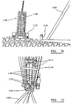
- remotely operable drilling apparatus 6 comprises a body formed from a frame 10 and drive means arranged to drill or drive annular pile 8, which is loaded in the remotely operable drilling apparatus 6, into the floor of a body of water.
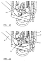
- the drive means comprises a power swivel 12 which attaches to the top of the pin pile by means of a drive head 11 ( Figure 22 ).
- the drive head 11 contains drive pins (not shown) arranged at equally space points around the outer diameter of the drive head.
- the drive head engages with machined locating slots (not shown) which are located in the annular pile locking collar 22 ( Figure 2 ).
- the drive head 11 can be released from the pin pile by rotating the power swivel in a reverse direction.
- the power swivel can be rotated in either a forward or reverse direction with an equal amount of torque being available in either direction.
- Delivery means is also provided which comprises a fluid conduit (not shown) located adjacent drive head 11 to enable flushing fluid and grout to be injected around annular pile 8.
- the power swivel 12 is raised and lowered by rack and pinion means 14 disposed on either side of the power swivel 12.
- rack and pinion means 14 disposed on either side of the power swivel 12.
- Different pin pile lengths can be accommodated in the drilling apparatus 6 by means of insertion of additional shortened pre-manufactured sections of the integrated frame and rack and pinion sections.
- rack and pinion means at one least hydraulic cylinder (not shown) could be used.
- centring and location of the remotely operable drilling apparatus onto the submerged structure to be pinned is assisted by guide means located on the remotely operable drilling apparatus.
- the guide means may comprise a female cone portion 16 disposed on the base of drilling apparatus 6.
- the female cone portion 16 is arranged to contact a male cone portion 18 disposed adjacent aperture 30 of submerged structure 32.
- Submerged structure 32 in the present example is a tripod having a platform 31 on to which a submerged turbine (not shown) is to be mounted.
- the tripod comprises three apertures or collars 30 through which piles are to be passed to pin the structure 32 to the seabed.
- annular pile 8 comprises a substantially hollow shaft portion 20, an anchor means which in the first embodiment is a locking member for providing a locking force, for example a locking collar 22 at a first end, and an annular bit 24 at a second end.
- the annular bit 24 forms a ring-like cutting shoe and is wider than the cylindrical portion 20 such that when annular bit 24 is drilled into the seabed an annulus is formed behind the annular bit 24.
- the locking member 22 is arranged to engage the edges of aperture 30 ( Figure 12 ) to resist removal of a portion of submerged structure 32 from the seabed.
- FIGs 26A to 26D show an alternative embodiment of an anchor member that can be used with remotely operable drilling apparatus 6.
- the anchor member comprises an annular pile 308 having a shaft 320 formed from outer 320A and inner 320B concentric cylindrical sleeves defining an annular channel 323 therebetween.
- An annular bit 324 is mounted to a first end of the shaft and anchor means such as a locking member 322 is mounted to a second end of the shaft 320.
- an attachment means for enabling a submerged structure to be tethered or attached to the annular pile may be mounted to the second end of the shaft.
- a path for fluid flow is defined from a first opening 322A in the locking member, through the annular channel 323 and through a second opening 323A defined by said inner sleeve.
- the annular bit 324 is mounted to the outer sleeve 320A and the second opening 323A is defined by the end of the inner sleeve.
- second openings may be formed at different points through the length of inner sleeve 320B.
- Pile 308 can be formed by welding a length of pipe to form an inner sleeve 320B in an existing annular pile. Pile 308 is very useful for overcoming a problem of annulus blockage.
- At least one guideline 34 is attached to an arm 38 and guide post 38A of submerged structure 32.
- Corresponding eyelets 36 and a post guide 36B are arranged on the drilling apparatus 6 through which the guidelines 34 can be fed.
- guidelines 34 Prior to being attached to the drilling apparatus 6, guidelines 34 are floated to the surface by buoys 40 ( Figures 1 and 11 ). Consequently, referring to Figure 1 , buoys 40 identify locations on the surface of the water 4 to which the remotely operable drilling apparatus 6 is to be submerged to perform a piling operation.
- umbilical means comprises at least one cable 50 to provide hydraulic or electrical power to the remotely operable drilling apparatus 6 from the surface vessel 2.
- the umbilical means may also include at least one hose 52 through which flushing fluid and/or grout can be provided to the delivery means as will be explained in further detail below.
- Pumping means (not shown) is located on vessel 2 to pump flushing fluid and/or grout through hose 52.
- the pumping means may comprise a flushing pump unit (not shown) mounted on drilling apparatus 6. This would mean that only a small hose for grout would be required from the surface, rather than a larger hose assembly for grout and flushing fluid.
- the umbilical 50, 52 may also comprise adapter means (not shown) arranged to enable the umbilical means to be disconnected from the surface vessel and attached to a buoy in the event of adverse weather conditions. This provides the advantage that in the event of bad weather and rough seas, the piling operation can be quickly interrupted and detached from the surface vessel 2 for safety. The buoy can then be retrieved and piling recommenced relatively quickly when conditions permit.
- a roller assembly 42 is provided on the surface of vessel 2.
- An annular pile 8 is loaded on the roller assembly 42 such that the locking collar 22 is arranged adjacent lower drilling aperture 7 of the drilling assembly 6.
- Annular pile 8 is then installed by running locking collar 22 rearwardly into aperture 7 such that the locking collar 22 engages the drive head 11 of power swivel 12.
- the power swivel 12 is then retracted along the rack and pinion means 14 to draw the annular pile 8 into the drilling apparatus 6 as shown in Figure 4 .
- retractable support clamping means such as upper locking clamps 15 are deployed to contact outer cylindrical surface 20 of annular pile 8 as shown in Figure 6 .
- Upper locking clamps 15 serve two functions. Firstly, they hold annular pile 8 on the centre line of the drilling apparatus 6 whilst being deployed. Secondly, upper clamps 15 also give initial stability whilst drilling to establish a spud of a hole until such time a predetermined hole depth as been established. At this point the upper clamps are retracted clear of the pin pile 8.
- buoys 40 are retrieved and guidelines 34 to which a predetermined pair of buoys 40 are attached are connected to surface vessel 2 by tensioning means.
- Tensioning means may for example comprise compensation air winches 54.
- Tension is set in guidelines 34 and this can be slackened during operations if required.
- the taut guidelines 34 can also be disconnected and buoyed off in the event of an emergency.
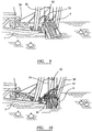
- An A-frame assembly 56 is used to raise the remotely operable drilling apparatus 6 into a vertical configuration and into the water as shown in Figures 8 through 10 .
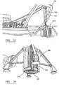
- Guidelines 34 can then be connected to eyelet 36 and post guide 38B of drilling apparatus 6 as shown in Figure 20 .
- the drilling apparatus 6 is then submerged and lowered down guidelines 34 towards aperture 30 of submerged apparatus 32. Submersion and lowering of the drilling apparatus 6 ideally takes place during slack tide when the current is at its weakest.
- Guide post 38A comes in to contact with post guide 38B and female conical guide 16 comes into contact with male conical guide 18 to locate the annular bit 24 of annular pile 8 into the aperture 30.
- clamping means such as lower locking clamps 17 are actuated to grip the portion of submerged structure 32 around the aperture. Drilling can now commence in response to delivery of power to the power swivel 12 via umbilical 50 and flushing fluid via the hose 52.
- drilling commences by powering power swivel (not shown) to rotate drive head 11 ( Figure 22 ) and therefore rotate annular pile 8.
- the power swivel is drawn downwardly by a pinion rolling along rack 13.
- Annular bit 24 is therefore biased against the sea bed and begins to cut an annulus 60 into the rock of seabed 64.
- upper clamps 15 are retracted to provide space for locking collar 22 to pass through and into contact with structure 32.
- the drive bore in collar 22 contains a circumferential sealing arrangement (not shown) to prevent leakage or loss of pressure during either normal flushing fluid or during any grouting operations. Accordingly, flushing fluid is pumped from the service vessel via drilling apparatus 6, through the centre of annular pile 8, up through annulus 60 and out of vent holes 67 to flush out debris 59 produced by the drilling.
- annular bit 24 creates an annulus 60 through which flushing fluid can pass down the centre of annular pile 8 and out up the sides of annulus 60 to lubricate and cool the annular bit 24 and remove debris 59.
- Flexible skirt 62 is provided on the base of submerged structure 32 to serve as a cofferdam around the annulus.
- Figure 20 shows the resulting configuration at the end of the grouting operation.
- the exhaust to water is via vent holes 67 formed in the circumference of the collar around aperture 30.
- the vent holes ensure that the grout is pumped into the annulus between the collar and the annular pile.
- Flexible skirt 62 serves as a cofferdam around the outer surface of the aperture to prevent scouring of the grout should there be any leakage under the footing of the submerged apparatus 32.
- a rubber flapper (not shown) is also provided inside the top of the pile. This prevents grout being pulled out of the inside of the pile by the vortex effect of the current.
- drive head 11 of power swivel 12 can then be detached from locking collar 22 and the lower clamps 17 retracted.
- Drilling apparatus 6 can then be retrieved to the surface leaving annular pile 8 embedded in the seabed and sealed in grout 66 contained in the annulus 60.
- the locking collar 22 of pin pile 8 therefore pins a portion of structure 32 around aperture 30 to the seabed.
- submerged structure 32 is a tripod having three apertures.
- the pinning procedure therefore has to be repeated three times in order to attach structure 32 fully to the seabed.
- the remotely operable drilling apparatus may drill the annular pile in to the seabed, and the grouting operation may be performed after by a different apparatus.
- the hole drilling operation can be controlled from a control room on vessel 2. Power and hydraulics are provided via the umbilical 50, 52 to the drilling apparatus 6.
- the umbilical 50, 52 can be disconnected and buoyed off in the event of rough weather and then retrieved to complete the drilling procedure. This can be done even when the drilling apparatus 6 is attached to the structure 32 at the seabed.
- the drilling apparatus 6 enables the drilling procedure to be conducted throughout the tidal cycle. Deployment and retrieval of the apparatus is preferably conducted during slack tide.
- a second embodiment of a drilling apparatus 106 does not use guidelines to be located on aperture 130 of structure 132.
- the movement of the drilling apparatus 106 can be controlled from the surface using cameras to locate the drilling apparatus 106 on aperture 130.
- a method of attaching an anchor member to a floor of a body of water, a remotely operable drilling apparatus, a system for attaching an anchor member to a floor of a body of water and an anchor member of a third embodiment of the invention is shown in Figure 27 to 50 , with parts common to the embodiment of Figure 1 to 23 shown with like reference numerals but increased by 200.
- a remotely operable drilling apparatus 206 is located on the deck of a vessel 202.
- a plurality of anchor members each comprising an annular pile 208 are arranged to be loaded into the drilling apparatus 206.
- Figure 28 shows the first stage of loading a pile 208 into the remotely operable drilling apparatus 206.
- the loading process is substantially the same as that of the first embodiment and described with reference to Figures 1 to 7 above, with the exception that when anchor member 208 has been fully retracted into apparatus 206, flexible skirt 262 is mounted to the underside of the drilling apparatus 206, making flexible skirt 262 the last item to be installed prior to deployment. Flexible skirt 262 can be attached to the drilling apparatus by means of breakaway attachments such as tie wraps.
- the remotely operable drilling apparatus 206 is now ready for deployment.
- the remotely operable drilling apparatus 206 comprises a body formed from a frame 210.
- a support means is provided to enable the remotely operable drilling apparatus 206 to support itself on a floor of a body of water 264 and provide a reaction force during drilling of the annular pile.
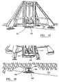
- the support means comprises a plurality of retractable legs 270 which can be retracted inwardly and outwardly of the frame 210 as shown in Figures 30 and 31 .
- the legs 270 may be deployed by hydraulic or electrical means acting on support beams 272.
- An adjustable shoe portion 274 is disposed on the end of each leg 270. Shoe portions 274 are adjustable to change the length from which and/or the angle at which the respective shoe portion 274 extends from the corresponding leg 270. In the example shown, shoe portions 274 are mounted on the end of piston assemblies 276 to enable the shoe 274 to extend relative to the leg 270. For example, as shown in Figures 37 and 38 , the shoe portion 274 closest to the front of the drawing is extended by piston 276 in order to level the drilling apparatus 206 to a condition in which the longitudinal axis of the annular pile 208 is substantially perpendicular to the floor of the body water 264 on which the drilling apparatus 206 rests.
- the pistons 276 can be controlled remotely from the surface under hydraulic and electrical power. Consequently, remotely operable drilling apparatus 276 does not require mounting to a submerged structure to provide a reaction force for drilling.
- annular pile 208 comprises a substantially hollow shaft 220, an anchor means which in this embodiment comprises attachment means 280 at a first end of the shaft 220, the attachment means being suitable for attachment to a submerged structure, and an annular bit 224 at a second end of the shaft 220.
- Annular bit 224 is a hardened cutting shoe arranged to be able to drill into a hard rock formation and form an annulus.
- attachment means 280 comprises a sleeve 282 rotatably mounted on shaft 220. At least one eye 284 is attached to the sleeve 280 to enable a submerged or floating structure to be tethered to the attachment means 280.
- a flexible skirt 262 is also provided to assist during the grouting operation in the same manner as described in accordance with the first embodiment. Consequently, the anchor member 208 of the second embodiment may be drilled and grouted into the floor of a body of water by remotely operable drilling apparatus 206 and then left in the floor of the body of water to enable a submerged structure to be tethered to the eye 284 at a later point in time.
- the anchor member 208 is loaded into the remotely operable drilling apparatus 206 as shown in Figures 27 to 29 .
- This process is substantially the same as has been described in connection with the first embodiment and therefore will not be described in any further detail here.
- one difference is the attachment of flexible skirt 262 to the underside of the drilling apparatus 206 prior to deployment as described above.
- A-frame assembly 256 is used to raise the remotely operable drilling apparatus 206 into a vertical condition and is then tilted over as shown in Figure 32 to lower the remotely operable drilling apparatus 206 into the water.
- retractable legs 270 are deployed to the outward condition as shown in Figures 31 and 32 .
- the drilling apparatus 206 is lowered on an umbilical comprising a cable 250 and at least one hose 252 to the floor 264 of the body of water.
- the remotely operable drilling apparatus 206 is then levelled on the floor of the body of water such that the longitudinal axis of the anchor member 208 is substantially perpendicular to the floor 264 of the body of water. This is accomplished by adjusting pistons 276 and feet 274 as explained above. Consequently, any angle or undulation in the floor of the body of water can be accounted for.
- Power swivel 212 is operated to rotate annular pile 208. Power swivel 212 is then advanced downwardly along rack 213. This causes cutting shoe 224 to drill an annulus 260 ( Figures 45 to 50 ) in the floor of the body of water. At the same time, flushing fluid is supplied to power swivel 212 via delivery means to flush out debris from the annulus being cut.
- a shoulder immediately below the anchor means engages the flexible skirt 262 forcing the breakaway attachments (not shown) to the drilling apparatus 206 to sever.
- the flexible skirt 262 comes into contact with the seabed, the flexible skirt is compressed further assisting in providing a seal once grout is in place.
- FIG. 51 to 53 A method of anchoring a structure to an anchor member of a fourth embodiment of the invention is shown in Figures 51 to 53 , with parts common to the embodiment of Figure 1 to 23 shown with like reference numerals but increased by 400.
- Anchor member 408 is drilled into the seabed 464 using one of the three methods described above in the first, second and third embodiments.
- attachment means 480 comprises first latching means 480A which is a collar for latching to second latching means (not shown).
- Second latching means may for example comprise spring loaded segments (not shown) disposed in the female connector portion 481 of a structure 432. Alternatively, spring loaded segments could be provided on the male attachment means 280. Once female connector 481 is lowered over attachment means 480, the spring loaded segments snap into place around first latching means 480A to hold the structure 432 in place and anchor it to the seabed.
- Locking bolts 483 are also provided and can be tightened to lock the structure 432 to the anchor member 408.
- connection can be hydraulically operated from the surface.
- the structure 432 is lowered over attachment means 480 and the segments are hydraulically operated using hydraulic pressure from a surface vessel causing the segments to engage collar 480A or alternatively, recesses (not shown) located around the circumference of attachment means 480.
- Bolts 483 can be operated by an ROV or diver.
- Structure 432 in the embodiments shown is a pile extension that can be used as a mounting for a generator for the production of electricity using the motion of current as the power source.
- the generator can either already be installed on pile extension 432 or can be installed at a later time.
- FIG. 54 to 57 A method of anchoring a structure to an anchor member of a fifth embodiment of the invention is shown in Figures 54 to 57 , with parts common to the embodiment of Figure 1 to 23 shown with like reference numerals but increased by 500.
- Anchor member 508 is drilled into the seabed 564 using one of the three methods described above in the first, second and third embodiments.
- attachment means 580 comprises first flange 580a having a plurality of holes 587 for receiving bolts 589 ( Figure 57 ).
- Structure 532 comprises a second flange 580b having a corresponding second plurality of bolt holes 587b.
- a female connector portion 585a disposed in the anchor means 580 is arranged to receive male connector portion 585b of structure 532 as shown moving from Figures 54 to 56 .
- Bolts 589 can then be used to bolt the structure 532 to the anchor member 508 and therefore the seabed 564.
- Structure 532 is shown as a pile extension that can be used as a mounting for a generator for the production of electricity using the motion of current as the power source.
- the generator can either already be installed on pile extension 532 or can be installed at a later time.
- a method of attaching an anchor member to a floor of a body of water, a remotely operable drilling apparatus, a system for attaching an anchor member to a floor of a body of water and an anchor member of a sixth embodiment of the invention is shown in Figure 58 to 69 .
- a remotely operable drilling apparatus comprises a vehicle 1002 having a body 1012 arranged to be remotely located adjacent a floor of a body of water.
- Vehicle 1002 is adapted to attach an anchor member in the form of an annular pile 1004 to a floor of a body of water 1006.
- Vehicle 1002 is moveable along the floor of the body of water 1006 on traction means such as caterpillar tracks 1008 or wheels.
- a piling apparatus 1010 which is substantially the same as the drilling apparatus of the earlier embodiments is mounted to the body 1012 of the vehicle 1002 and comprises a drive means such as power swivel 1014 adapted to drill an anchor member into the floor 1006 of a body of water.
- support structure 1032 is generally in the form of a tripod and comprises three hollow legs 1030.
- the support structure is arranged on a floor of a body of water and is used to support a submerged power generating turbine (not shown) on the seabed 1006.
- a flexible skirt 1034 forms a cofferdam and is located at the end of each leg 1030.
- Flexible skirt 1034 is formed from rubber or a similar material that acts as a grout retention skirt during grouting.
- annular piles 1004 In order to secure the support structure 1032 to the seabed 1006, annular piles 1004 must be drilled down into the seabed 1006 and grouted in place as will be explained below.
- a piling apparatus 1010 is pivotally mounted to body 1012 of vehicle 1002.
- the piling apparatus 1010 comprises a frame 1040 in which a drive means such as power swivel 1014 is mounted.
- the power swivel 1014 is able to advance downwardly along rack 1042 of a rack and pinion mechanism.
- at least one hydraulic cylinder could be used to move the power swivel 1014 downwardly.
- the frame 1040 and base portion 1044 form a guide means in which annular pile 1004 can be located.
- the power swivel 1014 can then be connected to the annular pile.
- Delivery means 1046 is also provided to enable flushing fluid during drilling and grout to be pumped through the annular pile 1004.
- the piling apparatus 1010 is pivotally mounted to the body 1012 to enable the drilling of piles on uneven surfaces and also to facilitate the location of the guide means on to the annular pile 1004.
- a grout hose 1050 and integrated hoisting, power and signalling cable 1052 connects the vehicle 1002 to a surface vessel. This enables electrical power and control signals to be provided from a surface vessel. Grout is pumped down hose 1050 from the surface vessel after drilling.
- a CCTV system (not shown) is also provided to enable controllers to control vehicle 1002.
- a plurality of thrusters 1054 is provided on the body 1012 to facilitate submersion and movement of the vehicle 1002 prior to landing on the seabed and additionally to provide thrust to maintain the excess grout exhausting from the structure not forming around the vehicle.
- Clamping means (not shown) is also provided in order to clamp the piling apparatus 1010 to an annular pile 1004. The clamping means may take the form of a pair of retractable jaws adapted to be removable clamped around cylindrical shaft 1020 of pile 1004.
- a method of attaching a support structure to a floor of a body of water such as a seabed 1006 using vehicle 1002 will now be described.
- the support structure is located on a surface vessel.
- Annular piles 1004 are then located in each leg 1030 of the support structure and the support structure is lowered to the seabed 1006.
- vehicle 1002 is then lowered to the seabed 1006 from a surface vessel which may be a smaller vessel than that used to lower support structure 1032.
- controllers on the surface vessel operate vehicle 1002 via cable 1052 to tilt the piling apparatus 1010 relative to vehicle body 1012 to ensure that the piling apparatus 1010 is in the correct orientation for drilling. Once the correct orientation has been attained, vehicle 1002 is moved forward and power swivel 1014 is connected to collar 1024 of the annular pile.
- the power swivel is then operated to rotate annular pile 1004.
- Power swivel 1014 is advanced down rack 1042 to drill the annular pile into the seabed 1006. This is achieved by cutting shoe 1026 drilling an annulus into the floor of the body of water 1006 as described in connection with the earlier embodiments.
- flushing fluid can be pumped from delivery means 1046 through the annulus to flush debris out from under skirt 1034.
- Figures 64 to 69 show the vehicle 1002 manoeuvring to a second leg 1030 and annular pile 1004 of support structure 1032 to repeat the drilling process. Once all three legs 1030 have been piled and grouted to the seabed 1006, the structure 1032 is pinned to the seabed 1006 and ready to support a turbine or the like.
- a remotely operable drilling apparatus for attaching an anchor member to a floor of a body of water of a seventh embodiment of the invention is shown in Figures 70 to 73 with parts common to the embodiment of Figures 58 to 69 denoted by like reference numerals but increased by 100.
- the piling apparatus is arranged to be loaded with a plurality of annular piles.
- Vehicle 1102 comprises a body 1112 to which a piling apparatus 1110 is interconnected.
- a piling apparatus 1110 In this embodiment, three piles 1104 are carried in the piling apparatus 1110. The piles are pre-loaded on the surface. Consequently, vehicle 1102 uses a carousel system to enable multiple piles 1104 to be carried by the vehicle and mounted and drilled through legs 1130 of support structure 1132.
- the vehicle 1102 is deployed from the surface with one pile 1104 loaded and connected to the power swivel 1114 ready for drilling.
- Two additional piles 1104 are carried by piling apparatus 1110 and are moveable under the action of hydraulic arms 1115 to be centralised in drilling apparatus 1110 and aligned with power swivel 1114 and with the aperture of a leg 1130 ready for drilling.
- the vehicle 1102 can be used to drill anchor members in the floor of a body of water without a support structure being present.
- piling apparatus 1110 can be used to drill annular piles directly in to the seabed.
- the annular piles may have anchoring portions such as rotatable eyes to enable interconnection with a support structure that is submerged some time after drilling of the piles.
Landscapes
- Engineering & Computer Science (AREA)
- Mining & Mineral Resources (AREA)
- Life Sciences & Earth Sciences (AREA)
- General Life Sciences & Earth Sciences (AREA)
- General Engineering & Computer Science (AREA)
- Structural Engineering (AREA)
- Paleontology (AREA)
- Civil Engineering (AREA)
- Geology (AREA)
- Physics & Mathematics (AREA)
- Fluid Mechanics (AREA)
- Environmental & Geological Engineering (AREA)
- Geochemistry & Mineralogy (AREA)
- Earth Drilling (AREA)
- Foundations (AREA)
- Piles And Underground Anchors (AREA)
- Placing Or Removing Of Piles Or Sheet Piles, Or Accessories Thereof (AREA)
Claims (17)
- Verfahren zur Anbringung eines Verankerungselements an einem Gewässergrund, wobei das Verfahren aufweist:Aufsetzen einer fernbedienbaren Bohrvorrichtung (6) an einen Gewässergrund angrenzend;dadurch gekennzeichnet, dass die fernbedienbare Bohrvorrichtung zum Treiben eines Verankerungselements ausgeführt ist, das einen Ringpfahl (8) aufweist, der einen im Wesentlichen hohlen Schaftteil (20), an einem ersten Ende davon einen Ringmeißel (24) und an einem zweiten Ende davon ein Verankerungsmittel (22) hat, wobei der Ringmeißel zum Bohren eines Ringraums in den Grund, in den der Ringpfahl zu treiben ist, angeordnet ist und das Verankerungsmittel zum Beschränken der Bewegung einer Struktur relativ zu dem Verankerungselement ausgeführt ist, und dass das Verfahren ferner aufweist:Bedienen der fernbedienbaren Bohrvorrichtung zum Bohren des genannten Ringpfahls in den Gewässergrund, indem der Ringmeißel einen Ringraum in den Gewässergrund schneidet, sodass das Verankerungsmittel über den Gewässergrund hinaus ragt; undFüllen des genannten Ringraums mit Verfestigungsmittel, um den Ringpfahl in dem genannten Ringraum zu halten und dem Entfernen des Ringpfahls von dem Gewässergrund zu widerstehen.
- Verfahren nach Anspruch 1, das eines oder mehr der folgenden Merkmale beinhaltet:(i) wobei der Schritt des Aufsetzens der fernbedienbaren Bohrvorrichtung an einen Gewässergrund angrenzend das Aufsetzen der fernbedienbaren Bohrvorrichtung an eine Öffnung (30) angrenzend aufweist, die an einer versenkten Struktur (32) ausgebildet ist, wobei die Öffnung zur Aufnahme eines Pfahls angeordnet ist; und
wobei der Schritt des Bedienens der fernbedienbaren Bohrvorrichtung das Treiben des genannten Ringpfahls durch die Öffnung und in den Gewässergrund durch Schneiden eines Ringraums mit dem Ringmeißel in den Gewässergrund so weit, dass das Verankerungsmittel, das ein Arretierungselement aufweist, gegen einen Teil der versenkten Struktur um die genannte Öffnung getrieben wird, um dem Entfernen der versenkten Struktur von dem Gewässergrund zu widerstehen, beinhaltet;(ii) wobei der Schritt des Aufsetzens einer fernbedienbaren Bohrvorrichtung an einen Gewässergrund angrenzend das Inkontaktbringen einer Stütze (270) der fernbedienbaren Bohrvorrichtung mit dem Gewässergrund aufweist, wobei die Stütze verstellbar ist, um das Ausgleichen der fernbedienbaren Bohrvorrichtung auf einen Zustand zu ermöglichen, in dem eine Längsachse des Ringpfahls im Wesentlichen lotrecht zum Gewässergrund ist;(iii) wobei der Schritt des Aufsetzens der fernbedienbaren Bohrvorrichtung an einen Gewässergrund angrenzend das Bedienen von Fahreinrichtungen (1008) der fernbedienbaren Bohrvorrichtung zum Bewegen der fernbedienbaren Bohrvorrichtung an einem Gewässergrund entlang zu einem Ort, an dem ein Verankerungselement in den Gewässergrund zu bohren ist, aufweist;(iv) wobei der Schritt des Bedienens der fernbedienbaren Bohrvorrichtung zum Bohren des genannten Ringpfahls in den Gewässergrund einen oder mehr der folgenden Schritte aufweist:a) Anbringen einer Treibeinrichtung (12) der fernbedienbaren Bohrvorrichtung an dem Ringpfahl und Bedienen der Treibeinrichtung zum Drehen und Drücken des Ringpfahls in den Gewässergrund oderb) Durchpumpen von Spülfluid durch den genannten Ringpfahl zum Entfernen von Bohrklein aus einem gebohrten Ringraum und Versehen des genannten Ringmeißels mit Schmierung und Kühlung;(v) wobei der Schritt des Füllens des genannten Ringraums mit Verfestigungsmittel, um den Ringpfahl in dem genannten Ringraum zu halten, das Bedienen einer Zuführeinrichtung der fernbedienbaren Bohrvorrichtung zum Füllen des genannten Ringraums mit Verfestigungsmittel aufweist;(vi) Trennen der fernbedienbaren Bohrvorrichtung von der versenkten Struktur und Zurückholen der fernbedienbaren Bohrvorrichtung zu einem Schiff oder(vii) Laden eines weiteren Ringpfahls auf die genannte fernbedienbare Bohrvorrichtung und Wiederholen des Verfahrens nach einem der vorhergehenden Ansprüche. - Verfahren nach Anspruch 2, das eines oder mehr der folgenden Merkmale beinhaltet:(i) wobei der Schritt des Aufsetzens einer fernbedienbaren Bohrvorrichtung auf der versenkten Struktur an eine zur Aufnahme eines Pfahls angeordnete Öffnung angrenzend einen oder mehr der folgenden Schritte aufweist:c) verschiebbares gegenseitiges Verbinden der fernbedienbaren Bohrvorrichtung mit wenigstens einem Führungsseil (34), wobei wenigstens ein genanntes Führungsseil an einem Ort an der versenkten Struktur angebracht wird, der an eine zur Aufnahme des Pfahls angeordnete Öffnung angrenzt, und Senken der fernbedienbaren Bohrvorrichtung an wenigsten einem genannten Führungsseil entlang, während das wenigstens eine genannte Führungsseil straff gespannt wird;d) Inkontaktbewegen einer Führung, die an der Basis (1044) der fernbedienbaren Bohrvorrichtung positioniert ist, mit einem Teil der versenkten Struktur, der an eine zur Aufnahme eines Pfahls angeordnete Öffnung angrenzt, um den genannten Ringmeißel auf die genannte Öffnung auszurichten; odere) Bedienen einer ersten Klemmeinrichtung (17) zum Festklemmen der genannten fernbedienbaren Bohrvorrichtung an die genannte Öffnung an der versenkten Struktur angrenzend; oder(ii) wobei der Schritt des Bedienens der fernbedienbaren Bohrvorrichtung das Bohren des genannten Ringpfahls in den Gewässergrund beinhaltet, indem der Ringmeißel einen Ringraum in den Gewässergrund schneidet, sodass das Verankerungsmittel, das Anbringungsmittel zur Anbringung an einer versenkten Struktur aufweist, über den Gewässergrund hinaus ragt.
- Verfahren zur Anbringung einer Struktur an einem Gewässergrund, wobei das Verfahren aufweist:Anbringen eines Verankerungselements an einem Gewässergrund nach dem Verfahren von Anspruch 1 undAnbringen einer Struktur an dem Verankerungsmittel des Verankerungselements.
- Verfahren nach Anspruch 4, wobei das Verankerungsmittel ein Anbringungsmittel (480) aufweist, das ein erstes Verriegelungsmittel (480A) hat, und die Struktur ein zweites Verriegelungsmittel aufweist, das zum Verriegeln mit dem ersten Verriegelungsmittel angeordnet ist, und wobei der Schritt des Anbringens der Struktur an dem Verankerungsmittel des Verankerungselements das Verriegeln des genannten ersten Verriegelungsmittels mit dem genannten zweiten Verriegelungsmittel aufweist.
- Fernbedienbare Bohrvorrichtung, die aufweist:einen Körper, der angeordnet ist, um an einen Gewässergrund angrenzend fernaufgesetzt zu werden;gekennzeichnet durch eine Treibeinrichtung (12), die zum Bohren eines Verankerungselements in einen Gewässergrund angeordnet ist, wobei das Verankerungselement einen Ringpfahl aufweist, der einen im Wesentlichen hohlen Schaftteil, einen Ringmeißel an einem ersten Ende davon und ein Verankerungsmittel an einem zweiten Ende davon hat, wobei der Ringmeißel zum Bohren eines Ringraums in den Grund angeordnet ist, in den der Ringpfahl zu bohren ist, und das Verankerungsmittel zum Beschränken der Bewegung einer Struktur relativ zu dem Verankerungselement ausgeführt ist.
- Vorrichtung nach Anspruch 6, die eine oder mehr der folgenden Merkmale beinhaltet:(i) die ferner eine Zuführeinrichtung aufweist, die zum Füllen des genannten Ringraums mit Verfestigungsmittel angeordnet ist, um den Ringpfahl in dem genannten Ringraum zu halten und dem Entfernen einer Struktur von dem Gewässergrund zu widerstehen;(ii) eine Führung, die an der Basis (1044) der fernbedienbaren Bohrvorrichtung positioniert ist, wobei die Führung zum Ausrichten des genannten Ringmeißels auf eine Öffnung einer versenkten Struktur angeordnet ist, wobei die Öffnung zur Aufnahme des Pfahls angeordnet ist;(iii) eine Klemmeinrichtung (17) zum Festklemmen der genannten fernbedienbaren Bohrvorrichtung an eine zur Aufnahme eines Pfahls angeordnete Öffnung angrenzend an einer versenkten Struktur;(iv) die ferner eine Stützeinrichtung (270) aufweist, die zum Inkontaktbringen mit einem Gewässergrund angeordnet ist, wobei die Stützeinrichtung verstellbar ist, um das Ausgleichen der fernbedienbaren Bohrvorrichtung auf einen Zustand zu ermöglichen, in dem eine Längsachse des Ringpfahls im Wesentlichen lotrecht zum Gewässergrund ist;(v) die ferner eine Fahreinrichtung (1008) aufweist, die zum Bewegen des Körpers am Gewässergrund entlang ausgeführt ist;(vi) wobei die Treibeinrichtung eines oder mehr der folgenden Merkmale aufweist:f) einen Drehkopf (12), der einen Treibkopf (11) aufweist, der zum auslösbaren Eingriff mit dem und Drehen des genannten Ringpfahl(s) angeordnet ist;g) eine Zahnstangentriebeinrichtung (14) oder wenigstens einen Hydraulikzylinder, die/der zum Bewegen des genannten Drehkopfs zum Gewässergrund hin angeordnet ist; oderh) eine zurückziehbare Stützenklemmeinrichtung, die zum Festhalten des genannten Ringpfahls in der fernbedienbaren Bohrvorrichtung vor dem Bohren und zum Bereitstellen von Stabilität während des Bohrens angeordnet ist; odervii) die ferner ein in die Vorrichtung geladenes Verankerungselement aufweist, wobei das Verankerungselement aufweist:einen Ringpfahl (8), der einen im Wesentlichen hohlen Schaftteil (20), an einem ersten Ende davon einen Ringmeißel (24) und an einem zweiten Ende davon ein Verankerungsmittel (22) hat, wobei der Ringmeißel zum Bohren eines Ringraums in den Grund, in den der Ringpfahl zu treiben ist, angeordnet ist und das Verankerungsmittel zum Beschränken der Bewegung einer Struktur relativ zu dem Verankerungselement ausgeführt ist.
- Vorrichtung nach Anspruch 7, die eines oder mehr der folgenden Merkmale beinhaltet:(i) wobei die genannte Führung einen konischen Aufnahmeteil (16) aufweist, der zur Anlage an einem entsprechenden konischen Steckteil (18) angeordnet ist, der um die zur Aufnahme eines Pfahls angeordnete genannte Öffnung positioniert ist;(ii) wobei die genannte Stütze mehrere zurückziehbare Beine (270) aufweist, wobei jedes genannte zurückziehbare Bein einen Schuhteil (274) aufweist, der einstellbar ist, um die Länge, von der, und/oder den Winkel, mit dem sich der jeweilige Schuh von dem entsprechenden Bein erstreckt, zu ändern;(iii) wobei die Treibeinrichtung relativ zum Körper verschwenkbar ist oder(iv) wobei die Rammvorrichtung zum Beladen mit mehreren Ringpfählen angeordnet ist.
- Vorrichtung nach Anspruch 8, die ferner wenigstens einen hydraulischen Arm (1115) aufweist, der angeordnet ist, um einen Ringpfahl in Ausrichtung mit der genannten Treibeinrichtung zu bewegen.
- System zur Anbringung eines Verankerungselements an einem Gewässergrund, wobei das System gekennzeichnet ist durch:eine fernbedienbare Bohrvorrichtung nach einem der Ansprüche 6 bis 9 undeine Versorgungseinrichtung (50), die zum Versorgen der genannten fernbedienbaren Bohrvorrichtung mit hydraulischer und/oder elektrischer Energie von einem Schiff und zum Versorgen der genannten Zuführeinrichtung mit Spülfluid und/oder Verfestigungsmittel von einem Schiff angeordnet ist.
- System nach Anspruch 10, das ferner eines oder mehr der folgenden Merkmale aufweist:i) eine Anschlusseinrichtung, die angeordnet ist, um zu ermöglichen, dass die Versorgungseinrichtung vom Schiff getrennt und an einer Boje angebracht wird;j) eine Pumpeinrichtung, die zum Pumpen von Spülfluid und/oder Verfestigungsmittel über die genannte Versorgungseinrichtung zu der genannten Zuführeinrichtung angeordnet ist; oderk) wenigstens ein Führungsseil (34), das an der versenkten Struktur an einem Ort angebracht ist, der an eine zur Aufnahme eines Pfahls angeordnete Öffnung angrenzt, wobei wenigstens ein genanntes Führungsseil angeordnet ist, um mit der genannten fernbedienbaren Bohrvorrichtung verbunden zu werden, um die fernbedienbare Bohrvorrichtung zu einem Ort an der genannten versenkten Struktur zu führen, der an eine zur Aufnahme eines Pfahls angeordnete Öffnung angrenzt, während das wenigstens eine genannte Führungsseil straff gespannt wird.
- System nach Anspruch 11, das ferner eine Spanneinrichtung (54) aufweist, die angeordnet ist, um wenigstens ein genanntes Führungsseil straff zu spannen.
- Verankerungselement, gekennzeichnet durch:einen Ringpfahl (8), der einen im Wesentlichen hohlen Schaftteil (20), an einem ersten Ende davon einen Ringmeißel (24) und an einem zweiten Ende davon ein Verankerungsmittel (22) hat, wobei der Ringmeißel zum Bohren eines Ringraums in den Grund, in den der Ringpfahl zu treiben ist, angeordnet ist und das Verankerungsmittel zum Beschränken der Bewegung einer Struktur relativ zu dem Verankerungselement ausgeführt ist.
- Verankerungselement nach Anspruch 13, das eines oder mehr der folgenden Merkmale beinhaltet:(i) wobei der genannte im Wesentlichen hohle Schaftteil einen Schaft mit einer äußeren (320A) und einer inneren (320B) konzentrischen zylindrischen Buchse aufweist, die dazwischen einen ringförmigen Kanal (323) definieren, und wobei der Ringmeißel an einem ersten Ende des Schafts montiert ist und das Verankerungsmittel an einem zweiten Ende des Schafts montiert ist; und
wobei von einer ersten Öffnung (322A) in dem Verankerungsmittel durch den genannten ringförmigen Kanal und durch eine zweite Öffnung (323A), die von der genannten inneren Buchse definiert wird, ein Fluiddurchflussweg definiert wird;(ii) wobei das genannte Verankerungsmittel ein Arretierungselement (322) aufweist, das angeordnet ist, um gegen einen Teil einer versenkten Struktur um eine Öffnung getrieben zu werden, um dem Entfernen der versenkten Struktur von dem Gewässergrund zu widerstehen; oder(iii) wobei das genannte Verankerungsmittel ein Anbringungsmittel (280) zur Anbringung an einer wenigstens teilweise versenkten Struktur aufweist. - Verankerungselement nach Anspruch 14, das eines oder mehr der folgenden Merkmale beinhaltet:(i) wobei der genannte Ringmeißel an der genannten äußeren Buchse montiert ist und die zweite Öffnung von einem Ende der inneren Buchse definiert wird;(ii) wobei das genannte Anbringungsmittel eine Buchse (282) aufweist, die drehbar an dem Verankerungselement montiert ist, wobei die Buchse wenigstens eine Öse (284) aufweist;(iii) wobei das genannte Anbringungsmittel ein erstes Verriegelungsmittel aufweist, das zum Verriegeln mit einem zweiten Verriegelungsmittel einer an dem genannten Anbringungsmittel anbringbaren Struktur angeordnet ist; oder(iv) wobei das genannte Anbringungsmittel einen ersten Flansch (580a) aufweist, der zum Verschrauben mit einem zweiten Flansch einer an dem genannten Anbringungsmittel anbringbaren Struktur angeordnet ist.
- Anordnung, die eine am Verankerungsmittel eines Verankerungselements nach einem der Ansprüche 13 bis 15 angebrachte Struktur aufweist.
- Anordnung nach Anspruch 16, die ferner einen flexiblen Mantel (62) aufweist, der an einen gebohrten Ringraum angrenzt, wobei der flexible Mantel angeordnet ist, um das Entfernen von Verfestigungsmittel aus dem Ringraum während und nach dem Bohren zu verhindern.
Priority Applications (1)
| Application Number | Priority Date | Filing Date | Title |
|---|---|---|---|
| EP10757257.0A EP2478157B1 (de) | 2009-09-14 | 2010-09-14 | Verfahren zur gründung einer versenkten struktur auf einem gewässergrund |
Applications Claiming Priority (6)
| Application Number | Priority Date | Filing Date | Title |
|---|---|---|---|
| EP09275075A EP2299006A1 (de) | 2009-09-14 | 2009-09-14 | Verfahren zur Gründung einer versenkten Struktur auf einem Gewässergrund |
| GBGB1003026.0A GB201003026D0 (en) | 2009-09-14 | 2010-02-23 | Method, apparatus and system for attaching an anchor member to a floor of a body of water |
| GBGB1004910.4A GB201004910D0 (en) | 2009-09-14 | 2010-03-24 | Method, apparatus and system for attaching an anchor member to a floor of a body of water |
| GBGB1013936.8A GB201013936D0 (en) | 2010-08-20 | 2010-08-20 | Vehicle for attaching an anchor member to a floor of a body of water |
| PCT/GB2010/051534 WO2011030167A1 (en) | 2009-09-14 | 2010-09-14 | Method, apparatus and system for attaching an anchor member to a floor of a body of water |
| EP10757257.0A EP2478157B1 (de) | 2009-09-14 | 2010-09-14 | Verfahren zur gründung einer versenkten struktur auf einem gewässergrund |
Publications (2)
| Publication Number | Publication Date |
|---|---|
| EP2478157A1 EP2478157A1 (de) | 2012-07-25 |
| EP2478157B1 true EP2478157B1 (de) | 2016-03-09 |
Family
ID=43531256
Family Applications (1)
| Application Number | Title | Priority Date | Filing Date |
|---|---|---|---|
| EP10757257.0A Active EP2478157B1 (de) | 2009-09-14 | 2010-09-14 | Verfahren zur gründung einer versenkten struktur auf einem gewässergrund |
Country Status (8)
| Country | Link |
|---|---|
| US (1) | US8998540B2 (de) |
| EP (1) | EP2478157B1 (de) |
| KR (2) | KR20120083410A (de) |
| CN (1) | CN102762796A (de) |
| AU (1) | AU2010293935A1 (de) |
| CA (1) | CA2774439C (de) |
| GB (1) | GB2485935B (de) |
| WO (1) | WO2011030167A1 (de) |
Families Citing this family (18)
| Publication number | Priority date | Publication date | Assignee | Title |
|---|---|---|---|---|
| AU2011258073B2 (en) | 2010-05-28 | 2015-07-09 | Lockheed Martin Corporation | Undersea anchoring system and method |
| CN102322219B (zh) * | 2011-05-26 | 2013-08-21 | 上海交通大学 | 海底射流钻井车 |
| AU2013214147B2 (en) | 2012-02-03 | 2017-03-30 | Vallourec Deutschland Gmbh | Foundation structure of an offshore plant, in particular an offshore wind turbine, which foundation structure is to be installed at a low noise level, and installation method therefor |
| NL2012527B1 (en) * | 2014-03-28 | 2016-02-10 | Bluemarine Offshore Yard Service Bv | Method for lowering a subsea structure having a substantially flat support base into the water through the splash zone. |
| KR101559472B1 (ko) * | 2014-08-18 | 2015-10-13 | (주)동명기술공단종합건축사사무소 | 수중 지지구조물용 기초부 시공방법 |
| CN104612148B (zh) * | 2014-12-29 | 2017-01-04 | 中铁大桥局集团有限公司 | 一种将系泊缆绳锚固到水下的装置及方法 |
| CN106522256B (zh) * | 2016-10-31 | 2018-07-10 | 王燏斌 | 一种螺旋凹槽筒形基础及制造方法和施工方法 |
| CN106522255A (zh) * | 2016-10-31 | 2017-03-22 | 王燏斌 | 底部带刀的单壁螺旋筒形基础及其施工法 |
| US10822948B2 (en) * | 2017-12-28 | 2020-11-03 | Burrell Mining Products, Inc. | Mine roof support, pre-installation assembly for same, and method of installation |
| US10623703B2 (en) | 2018-02-28 | 2020-04-14 | Schlumberger Technology Corporation | CCTV system |
| EP3584372B1 (de) * | 2018-06-18 | 2022-08-17 | Vallourec Deutschland GmbH | Pfahlinstallationssystem für eine offshore-fundamentkonstruktion und verfahren zum installieren eines pfahls |
| MX2021012317A (es) | 2019-04-11 | 2021-11-12 | Burrell Mining Products Inc | Soporte de techo de mina, montaje de preinstalacion para el mismo y metodo de instalacion. |
| CN111546506A (zh) * | 2020-05-18 | 2020-08-18 | 中亿丰建设集团股份有限公司 | 水下钢筋混凝土板切割方法 |
| CN116623720B (zh) * | 2022-02-11 | 2024-10-29 | 上海勘测设计研究院有限公司 | 一种海上风电桩基的自维护防冲刷装置 |
| CN114875938B (zh) * | 2022-05-12 | 2024-03-08 | 南京西部路桥集团有限公司 | 一种装配式钢筋混凝土围堰及其施工方法 |
| EP4594593A1 (de) * | 2022-09-26 | 2025-08-06 | Itrec B.V. | Bohranordnung zum ausheben vertikaler ringförmiger hohlräume im meeresboden |
| NL2033956B1 (en) * | 2023-01-12 | 2024-07-22 | Itrec Bv | Drill assembly for excavating vertical annular cavities in the seafloor |
| CN116791555B (zh) * | 2023-08-29 | 2023-11-17 | 西南石油大学 | 一种钻井平台桩靴结构 |
Family Cites Families (19)
| Publication number | Priority date | Publication date | Assignee | Title |
|---|---|---|---|---|
| FR2018085A1 (en) * | 1968-09-13 | 1970-05-29 | Divcon Int Ltd | Underwater drilling apparatus operated by - a fluid pumping device mounted on a vessel |
| US3646598A (en) * | 1969-06-25 | 1972-02-29 | Bolt Associates Inc | Pile driver systems apparatus and method for driving a pile |
| US3779322A (en) * | 1972-03-24 | 1973-12-18 | Milwaukee Boiler Manuf Co | Machine for sinking vertical shafts |
| US3984991A (en) | 1975-03-17 | 1976-10-12 | A-Z International Tool Company | Anchor and method of setting anchor |
| JPS60223523A (ja) * | 1984-04-18 | 1985-11-08 | Mitsui Concrete Kogyo Kk | くい施工工法 |
| SE444698B (sv) | 1984-09-05 | 1986-04-28 | Kahlman Innovation Ab | Submarin elementidrivningsanordning |
| FR2605657A1 (fr) | 1986-10-22 | 1988-04-29 | Soletanche | Procede pour la realisation d'un pieu dans le sol, machine de forage et dispositif pour la mise en oeuvre de ce procede |
| US6085851A (en) * | 1996-05-03 | 2000-07-11 | Transocean Offshore Inc. | Multi-activity offshore exploration and/or development drill method and apparatus |
| WO1999046449A1 (en) * | 1998-03-10 | 1999-09-16 | Nippon Steel Corporation | Rotation buried pile and execution management method therefor |
| GB2364728B (en) * | 1998-05-16 | 2002-12-04 | Duncan Cuthill | Method of and apparatus for installing a pile underwater to create a mooring anchorage |
| CN2500715Y (zh) * | 2001-09-07 | 2002-07-17 | 天津大学 | 底部实施振动下沉安装大型混凝土圆筒结构的装置 |
| FR2841293B1 (fr) * | 2002-06-19 | 2006-03-03 | Bouygues Offshore | Conduite de guidage telescopique de forage en mer |
| NO320938B1 (no) * | 2002-08-13 | 2006-02-13 | Hammerfest Strom As | Anordning for fundamentering av en installasjon pa en havbunn samt en fremgangsmate for installasjon av anordningen |
| GB0520891D0 (en) * | 2005-10-14 | 2005-11-23 | Tidal Generation Ltd | Foundation structure for water current energy system |
| GB2436320A (en) | 2006-03-13 | 2007-09-26 | John Richard Carew Armstrong | Deep water remote drilled anchoring system |
| JP2007247218A (ja) * | 2006-03-15 | 2007-09-27 | Toa Harbor Works Co Ltd | 水中削岩装置および水中削岩方法 |
| CN101255701A (zh) * | 2007-01-25 | 2008-09-03 | 天津市海王星海上工程技术有限公司 | 一种海上混合式基础 |
| GB2448358B (en) | 2007-04-12 | 2009-07-08 | Tidal Generation Ltd | Installation of underwater ground anchorages |
| CN101363223B (zh) * | 2007-08-06 | 2010-05-19 | 中国海洋石油总公司 | 水下打桩导向架 |
-
2010
- 2010-09-14 EP EP10757257.0A patent/EP2478157B1/de active Active
- 2010-09-14 CN CN2010800415512A patent/CN102762796A/zh active Pending
- 2010-09-14 GB GB1203378.3A patent/GB2485935B/en active Active
- 2010-09-14 CA CA2774439A patent/CA2774439C/en active Active
- 2010-09-14 US US13/395,785 patent/US8998540B2/en active Active
- 2010-09-14 WO PCT/GB2010/051534 patent/WO2011030167A1/en not_active Ceased
- 2010-09-14 KR KR1020127009611A patent/KR20120083410A/ko not_active Ceased
- 2010-09-14 AU AU2010293935A patent/AU2010293935A1/en not_active Abandoned
- 2010-09-14 KR KR20157007670A patent/KR20150038743A/ko not_active Withdrawn
Also Published As
| Publication number | Publication date |
|---|---|
| US8998540B2 (en) | 2015-04-07 |
| EP2478157A1 (de) | 2012-07-25 |
| KR20150038743A (ko) | 2015-04-08 |
| CA2774439A1 (en) | 2011-03-17 |
| GB2485935A (en) | 2012-05-30 |
| GB2485935B (en) | 2015-03-04 |
| CN102762796A (zh) | 2012-10-31 |
| KR20120083410A (ko) | 2012-07-25 |
| WO2011030167A1 (en) | 2011-03-17 |
| AU2010293935A1 (en) | 2012-04-19 |
| GB201203378D0 (en) | 2012-04-11 |
| CA2774439C (en) | 2018-10-23 |
| US20120243945A1 (en) | 2012-09-27 |
Similar Documents
| Publication | Publication Date | Title |
|---|---|---|
| EP2478157B1 (de) | Verfahren zur gründung einer versenkten struktur auf einem gewässergrund | |
| JP5591319B2 (ja) | 支柱又はパイルを設置する方法及び装置 | |
| US6536993B2 (en) | Pile and method for installing same | |
| EP2683876B1 (de) | Verfahren und vorrichtung zur herstellung von off shore gründungen | |
| US8845235B2 (en) | Installation of underwater ground anchorages | |
| US6113315A (en) | Recoverable system for mooring mobile offshore drilling units | |
| US4062313A (en) | Installation of vertically moored platforms | |
| US3976021A (en) | Installation of vertically moored platform | |
| US20080226398A1 (en) | Installation of Underwater Anchorages | |
| US20100296875A1 (en) | Underwater foundation | |
| KR101087161B1 (ko) | 지형조건 적응형 지반천공 가이드장치 | |
| JP2004517233A (ja) | 回転式ダウンホールコア堀り装置、及びこのような回転式コア堀り装置を備えた回転式コア堀りシステム | |
| EP2299006A1 (de) | Verfahren zur Gründung einer versenkten Struktur auf einem Gewässergrund | |
| US11781385B1 (en) | Subsea coiled tubing drilling system and subsea drilling device thereof | |
| US20230113664A1 (en) | System and method for suction anchor deployment | |
| US6715962B2 (en) | Assembly and floatation method for drilling drivepipe | |
| JP2019060227A (ja) | ジャケット構造体の構築方法 | |
| AU2006300972B2 (en) | Installation of underwater anchorages | |
| US3424241A (en) | Method for drilling and working in offshore wells | |
| US20010027878A1 (en) | Assembly and floatation method for drilling drivepipe and jarring system | |
| GB2447782A (en) | Underwater structure leveled using screw jacks |
Legal Events
| Date | Code | Title | Description |
|---|---|---|---|
| PUAI | Public reference made under article 153(3) epc to a published international application that has entered the european phase |
Free format text: ORIGINAL CODE: 0009012 |
|
| 17P | Request for examination filed |
Effective date: 20120228 |
|
| AK | Designated contracting states |
Kind code of ref document: A1 Designated state(s): AL AT BE BG CH CY CZ DE DK EE ES FI FR GB GR HR HU IE IS IT LI LT LU LV MC MK MT NL NO PL PT RO SE SI SK SM TR |
|
| DAX | Request for extension of the european patent (deleted) | ||
| GRAP | Despatch of communication of intention to grant a patent |
Free format text: ORIGINAL CODE: EPIDOSNIGR1 |
|
| INTG | Intention to grant announced |
Effective date: 20150903 |
|
| GRAS | Grant fee paid |
Free format text: ORIGINAL CODE: EPIDOSNIGR3 |
|
| GRAA | (expected) grant |
Free format text: ORIGINAL CODE: 0009210 |
|
| AK | Designated contracting states |
Kind code of ref document: B1 Designated state(s): AL AT BE BG CH CY CZ DE DK EE ES FI FR GB GR HR HU IE IS IT LI LT LU LV MC MK MT NL NO PL PT RO SE SI SK SM TR |
|
| REG | Reference to a national code |
Ref country code: GB Ref legal event code: FG4D |
|
| REG | Reference to a national code |
Ref country code: AT Ref legal event code: REF Ref document number: 779646 Country of ref document: AT Kind code of ref document: T Effective date: 20160315 Ref country code: CH Ref legal event code: EP |
|
| REG | Reference to a national code |
Ref country code: IE Ref legal event code: FG4D |
|
| REG | Reference to a national code |
Ref country code: DE Ref legal event code: R096 Ref document number: 602010031064 Country of ref document: DE |
|
| REG | Reference to a national code |
Ref country code: LT Ref legal event code: MG4D |
|
| REG | Reference to a national code |
Ref country code: NL Ref legal event code: MP Effective date: 20160309 |
|
| PG25 | Lapsed in a contracting state [announced via postgrant information from national office to epo] |
Ref country code: GR Free format text: LAPSE BECAUSE OF FAILURE TO SUBMIT A TRANSLATION OF THE DESCRIPTION OR TO PAY THE FEE WITHIN THE PRESCRIBED TIME-LIMIT Effective date: 20160610 Ref country code: HR Free format text: LAPSE BECAUSE OF FAILURE TO SUBMIT A TRANSLATION OF THE DESCRIPTION OR TO PAY THE FEE WITHIN THE PRESCRIBED TIME-LIMIT Effective date: 20160309 Ref country code: ES Free format text: LAPSE BECAUSE OF FAILURE TO SUBMIT A TRANSLATION OF THE DESCRIPTION OR TO PAY THE FEE WITHIN THE PRESCRIBED TIME-LIMIT Effective date: 20160309 Ref country code: NO Free format text: LAPSE BECAUSE OF FAILURE TO SUBMIT A TRANSLATION OF THE DESCRIPTION OR TO PAY THE FEE WITHIN THE PRESCRIBED TIME-LIMIT Effective date: 20160609 Ref country code: FI Free format text: LAPSE BECAUSE OF FAILURE TO SUBMIT A TRANSLATION OF THE DESCRIPTION OR TO PAY THE FEE WITHIN THE PRESCRIBED TIME-LIMIT Effective date: 20160309 |
|
| REG | Reference to a national code |
Ref country code: AT Ref legal event code: MK05 Ref document number: 779646 Country of ref document: AT Kind code of ref document: T Effective date: 20160309 |
|
| PG25 | Lapsed in a contracting state [announced via postgrant information from national office to epo] |
Ref country code: SE Free format text: LAPSE BECAUSE OF FAILURE TO SUBMIT A TRANSLATION OF THE DESCRIPTION OR TO PAY THE FEE WITHIN THE PRESCRIBED TIME-LIMIT Effective date: 20160309 Ref country code: LT Free format text: LAPSE BECAUSE OF FAILURE TO SUBMIT A TRANSLATION OF THE DESCRIPTION OR TO PAY THE FEE WITHIN THE PRESCRIBED TIME-LIMIT Effective date: 20160309 Ref country code: LV Free format text: LAPSE BECAUSE OF FAILURE TO SUBMIT A TRANSLATION OF THE DESCRIPTION OR TO PAY THE FEE WITHIN THE PRESCRIBED TIME-LIMIT Effective date: 20160309 Ref country code: PL Free format text: LAPSE BECAUSE OF FAILURE TO SUBMIT A TRANSLATION OF THE DESCRIPTION OR TO PAY THE FEE WITHIN THE PRESCRIBED TIME-LIMIT Effective date: 20160309 Ref country code: NL Free format text: LAPSE BECAUSE OF FAILURE TO SUBMIT A TRANSLATION OF THE DESCRIPTION OR TO PAY THE FEE WITHIN THE PRESCRIBED TIME-LIMIT Effective date: 20160309 |
|
| REG | Reference to a national code |
Ref country code: FR Ref legal event code: PLFP Year of fee payment: 7 |
|
| PG25 | Lapsed in a contracting state [announced via postgrant information from national office to epo] |
Ref country code: EE Free format text: LAPSE BECAUSE OF FAILURE TO SUBMIT A TRANSLATION OF THE DESCRIPTION OR TO PAY THE FEE WITHIN THE PRESCRIBED TIME-LIMIT Effective date: 20160309 Ref country code: IS Free format text: LAPSE BECAUSE OF FAILURE TO SUBMIT A TRANSLATION OF THE DESCRIPTION OR TO PAY THE FEE WITHIN THE PRESCRIBED TIME-LIMIT Effective date: 20160709 |
|
| PG25 | Lapsed in a contracting state [announced via postgrant information from national office to epo] |
Ref country code: SK Free format text: LAPSE BECAUSE OF FAILURE TO SUBMIT A TRANSLATION OF THE DESCRIPTION OR TO PAY THE FEE WITHIN THE PRESCRIBED TIME-LIMIT Effective date: 20160309 Ref country code: SM Free format text: LAPSE BECAUSE OF FAILURE TO SUBMIT A TRANSLATION OF THE DESCRIPTION OR TO PAY THE FEE WITHIN THE PRESCRIBED TIME-LIMIT Effective date: 20160309 Ref country code: RO Free format text: LAPSE BECAUSE OF FAILURE TO SUBMIT A TRANSLATION OF THE DESCRIPTION OR TO PAY THE FEE WITHIN THE PRESCRIBED TIME-LIMIT Effective date: 20160309 Ref country code: AT Free format text: LAPSE BECAUSE OF FAILURE TO SUBMIT A TRANSLATION OF THE DESCRIPTION OR TO PAY THE FEE WITHIN THE PRESCRIBED TIME-LIMIT Effective date: 20160309 Ref country code: PT Free format text: LAPSE BECAUSE OF FAILURE TO SUBMIT A TRANSLATION OF THE DESCRIPTION OR TO PAY THE FEE WITHIN THE PRESCRIBED TIME-LIMIT Effective date: 20160711 Ref country code: CZ Free format text: LAPSE BECAUSE OF FAILURE TO SUBMIT A TRANSLATION OF THE DESCRIPTION OR TO PAY THE FEE WITHIN THE PRESCRIBED TIME-LIMIT Effective date: 20160309 |
|
| REG | Reference to a national code |
Ref country code: DE Ref legal event code: R097 Ref document number: 602010031064 Country of ref document: DE |
|
| PG25 | Lapsed in a contracting state [announced via postgrant information from national office to epo] |
Ref country code: BE Free format text: LAPSE BECAUSE OF FAILURE TO SUBMIT A TRANSLATION OF THE DESCRIPTION OR TO PAY THE FEE WITHIN THE PRESCRIBED TIME-LIMIT Effective date: 20160309 Ref country code: IT Free format text: LAPSE BECAUSE OF FAILURE TO SUBMIT A TRANSLATION OF THE DESCRIPTION OR TO PAY THE FEE WITHIN THE PRESCRIBED TIME-LIMIT Effective date: 20160309 |
|
| PLBE | No opposition filed within time limit |
Free format text: ORIGINAL CODE: 0009261 |
|
| STAA | Information on the status of an ep patent application or granted ep patent |
Free format text: STATUS: NO OPPOSITION FILED WITHIN TIME LIMIT |
|
| PG25 | Lapsed in a contracting state [announced via postgrant information from national office to epo] |
Ref country code: DK Free format text: LAPSE BECAUSE OF FAILURE TO SUBMIT A TRANSLATION OF THE DESCRIPTION OR TO PAY THE FEE WITHIN THE PRESCRIBED TIME-LIMIT Effective date: 20160309 |
|
| 26N | No opposition filed |
Effective date: 20161212 |
|
| PG25 | Lapsed in a contracting state [announced via postgrant information from national office to epo] |
Ref country code: BG Free format text: LAPSE BECAUSE OF FAILURE TO SUBMIT A TRANSLATION OF THE DESCRIPTION OR TO PAY THE FEE WITHIN THE PRESCRIBED TIME-LIMIT Effective date: 20160609 |
|
| PG25 | Lapsed in a contracting state [announced via postgrant information from national office to epo] |
Ref country code: MC Free format text: LAPSE BECAUSE OF FAILURE TO SUBMIT A TRANSLATION OF THE DESCRIPTION OR TO PAY THE FEE WITHIN THE PRESCRIBED TIME-LIMIT Effective date: 20160309 |
|
| REG | Reference to a national code |
Ref country code: CH Ref legal event code: PL |
|
| GBPC | Gb: european patent ceased through non-payment of renewal fee |
Effective date: 20160914 |
|
| PG25 | Lapsed in a contracting state [announced via postgrant information from national office to epo] |
Ref country code: SI Free format text: LAPSE BECAUSE OF FAILURE TO SUBMIT A TRANSLATION OF THE DESCRIPTION OR TO PAY THE FEE WITHIN THE PRESCRIBED TIME-LIMIT Effective date: 20160309 |
|
| PG25 | Lapsed in a contracting state [announced via postgrant information from national office to epo] |
Ref country code: CH Free format text: LAPSE BECAUSE OF NON-PAYMENT OF DUE FEES Effective date: 20160930 Ref country code: GB Free format text: LAPSE BECAUSE OF NON-PAYMENT OF DUE FEES Effective date: 20160914 Ref country code: LI Free format text: LAPSE BECAUSE OF NON-PAYMENT OF DUE FEES Effective date: 20160930 |
|
| PG25 | Lapsed in a contracting state [announced via postgrant information from national office to epo] |
Ref country code: LU Free format text: LAPSE BECAUSE OF NON-PAYMENT OF DUE FEES Effective date: 20160914 |
|
| REG | Reference to a national code |
Ref country code: FR Ref legal event code: PLFP Year of fee payment: 8 |
|
| REG | Reference to a national code |
Ref country code: GB Ref legal event code: S27 Free format text: APPLICATION FILED; APPLICATION TO AMEND SPECIFICATION UNDER SECTION 27 FILED ON 18 JANUARY 2018 |
|
| PG25 | Lapsed in a contracting state [announced via postgrant information from national office to epo] |
Ref country code: HU Free format text: LAPSE BECAUSE OF FAILURE TO SUBMIT A TRANSLATION OF THE DESCRIPTION OR TO PAY THE FEE WITHIN THE PRESCRIBED TIME-LIMIT; INVALID AB INITIO Effective date: 20100914 Ref country code: CY Free format text: LAPSE BECAUSE OF FAILURE TO SUBMIT A TRANSLATION OF THE DESCRIPTION OR TO PAY THE FEE WITHIN THE PRESCRIBED TIME-LIMIT Effective date: 20160309 |
|
| PG25 | Lapsed in a contracting state [announced via postgrant information from national office to epo] |
Ref country code: MT Free format text: LAPSE BECAUSE OF NON-PAYMENT OF DUE FEES Effective date: 20160930 Ref country code: TR Free format text: LAPSE BECAUSE OF FAILURE TO SUBMIT A TRANSLATION OF THE DESCRIPTION OR TO PAY THE FEE WITHIN THE PRESCRIBED TIME-LIMIT Effective date: 20160309 Ref country code: MK Free format text: LAPSE BECAUSE OF FAILURE TO SUBMIT A TRANSLATION OF THE DESCRIPTION OR TO PAY THE FEE WITHIN THE PRESCRIBED TIME-LIMIT Effective date: 20160309 |
|
| REG | Reference to a national code |
Ref country code: GB Ref legal event code: S27 Free format text: APPLICATION OPEN FOR OPPOSITION; PATENTS FORM 15 GIVING THE COMPTROLLER NOTICE OF OPPOSITION TO THE AMENDMENTS. YOU ALSO NEED TO FILE TWO COPIES OF A STATEMENT SETTING OUT FULLY THE FACTS OF YOUR CASE AND THE RELIEF THAT YOU ARE SEEKING TITLE OF PATENT: METHOD, APPARATUS AND SYSTEM FOR ATTACHING AN ANCHOR MEMBER TO A FLOOR OF A BODY OF WATER INTERNATIONAL CLASSIFICATION: E02D NAME OF PROPRIETOR: BLADE OFFSHORE SERVICES LTD THESE AMENDMENTS MAY BE VIEWED ON OUR WEBSITE |
|
| REG | Reference to a national code |
Ref country code: FR Ref legal event code: PLFP Year of fee payment: 9 |
|
| PG25 | Lapsed in a contracting state [announced via postgrant information from national office to epo] |
Ref country code: AL Free format text: LAPSE BECAUSE OF FAILURE TO SUBMIT A TRANSLATION OF THE DESCRIPTION OR TO PAY THE FEE WITHIN THE PRESCRIBED TIME-LIMIT Effective date: 20160309 |
|
| REG | Reference to a national code |
Ref country code: GB Ref legal event code: S27 Free format text: SPECIFICATION AMENDED; APPLICATION TO AMEND SPECIFICATION UNDER SECTION 27 FILED ON 18 JANUARY 2018 ALLOWED ON 5 DECEMBER 2018 |
|
| PGFP | Annual fee paid to national office [announced via postgrant information from national office to epo] |
Ref country code: FR Payment date: 20250929 Year of fee payment: 16 |
|
| PGFP | Annual fee paid to national office [announced via postgrant information from national office to epo] |
Ref country code: IE Payment date: 20250929 Year of fee payment: 16 |
|
| PGFP | Annual fee paid to national office [announced via postgrant information from national office to epo] |
Ref country code: DE Payment date: 20250929 Year of fee payment: 16 |