EP2478276B1 - Soupape pour turbomachine - Google Patents
Soupape pour turbomachine Download PDFInfo
- Publication number
- EP2478276B1 EP2478276B1 EP10755154.1A EP10755154A EP2478276B1 EP 2478276 B1 EP2478276 B1 EP 2478276B1 EP 10755154 A EP10755154 A EP 10755154A EP 2478276 B1 EP2478276 B1 EP 2478276B1
- Authority
- EP
- European Patent Office
- Prior art keywords
- valve
- line
- valve body
- supply line
- steam
- Prior art date
- Legal status (The legal status is an assumption and is not a legal conclusion. Google has not performed a legal analysis and makes no representation as to the accuracy of the status listed.)
- Not-in-force
Links
- 238000011161 development Methods 0.000 description 3
- 230000018109 developmental process Effects 0.000 description 3
- 230000005540 biological transmission Effects 0.000 description 1
- 230000000694 effects Effects 0.000 description 1
- 230000007246 mechanism Effects 0.000 description 1
- 230000001105 regulatory effect Effects 0.000 description 1
- 238000011144 upstream manufacturing Methods 0.000 description 1
Images


Classifications
-
- F—MECHANICAL ENGINEERING; LIGHTING; HEATING; WEAPONS; BLASTING
- F16—ENGINEERING ELEMENTS AND UNITS; GENERAL MEASURES FOR PRODUCING AND MAINTAINING EFFECTIVE FUNCTIONING OF MACHINES OR INSTALLATIONS; THERMAL INSULATION IN GENERAL
- F16K—VALVES; TAPS; COCKS; ACTUATING-FLOATS; DEVICES FOR VENTING OR AERATING
- F16K11/00—Multiple-way valves, e.g. mixing valves; Pipe fittings incorporating such valves
- F16K11/02—Multiple-way valves, e.g. mixing valves; Pipe fittings incorporating such valves with all movable sealing faces moving as one unit
- F16K11/08—Multiple-way valves, e.g. mixing valves; Pipe fittings incorporating such valves with all movable sealing faces moving as one unit comprising only taps or cocks
- F16K11/085—Multiple-way valves, e.g. mixing valves; Pipe fittings incorporating such valves with all movable sealing faces moving as one unit comprising only taps or cocks with cylindrical plug
- F16K11/0853—Multiple-way valves, e.g. mixing valves; Pipe fittings incorporating such valves with all movable sealing faces moving as one unit comprising only taps or cocks with cylindrical plug having all the connecting conduits situated in a single plane perpendicular to the axis of the plug
-
- F—MECHANICAL ENGINEERING; LIGHTING; HEATING; WEAPONS; BLASTING
- F01—MACHINES OR ENGINES IN GENERAL; ENGINE PLANTS IN GENERAL; STEAM ENGINES
- F01D—NON-POSITIVE DISPLACEMENT MACHINES OR ENGINES, e.g. STEAM TURBINES
- F01D17/00—Regulating or controlling by varying flow
- F01D17/10—Final actuators
- F01D17/12—Final actuators arranged in stator parts
- F01D17/14—Final actuators arranged in stator parts varying effective cross-sectional area of nozzles or guide conduits
- F01D17/141—Final actuators arranged in stator parts varying effective cross-sectional area of nozzles or guide conduits by means of shiftable members or valves obturating part of the flow path
- F01D17/145—Final actuators arranged in stator parts varying effective cross-sectional area of nozzles or guide conduits by means of shiftable members or valves obturating part of the flow path by means of valves, e.g. for steam turbines
-
- F—MECHANICAL ENGINEERING; LIGHTING; HEATING; WEAPONS; BLASTING
- F16—ENGINEERING ELEMENTS AND UNITS; GENERAL MEASURES FOR PRODUCING AND MAINTAINING EFFECTIVE FUNCTIONING OF MACHINES OR INSTALLATIONS; THERMAL INSULATION IN GENERAL
- F16K—VALVES; TAPS; COCKS; ACTUATING-FLOATS; DEVICES FOR VENTING OR AERATING
- F16K11/00—Multiple-way valves, e.g. mixing valves; Pipe fittings incorporating such valves
- F16K11/02—Multiple-way valves, e.g. mixing valves; Pipe fittings incorporating such valves with all movable sealing faces moving as one unit
- F16K11/06—Multiple-way valves, e.g. mixing valves; Pipe fittings incorporating such valves with all movable sealing faces moving as one unit comprising only sliding valves, i.e. sliding closure elements
- F16K11/065—Multiple-way valves, e.g. mixing valves; Pipe fittings incorporating such valves with all movable sealing faces moving as one unit comprising only sliding valves, i.e. sliding closure elements with linearly sliding closure members
- F16K11/07—Multiple-way valves, e.g. mixing valves; Pipe fittings incorporating such valves with all movable sealing faces moving as one unit comprising only sliding valves, i.e. sliding closure elements with linearly sliding closure members with cylindrical slides
- F16K11/0716—Multiple-way valves, e.g. mixing valves; Pipe fittings incorporating such valves with all movable sealing faces moving as one unit comprising only sliding valves, i.e. sliding closure elements with linearly sliding closure members with cylindrical slides with fluid passages through the valve member
-
- F—MECHANICAL ENGINEERING; LIGHTING; HEATING; WEAPONS; BLASTING
- F05—INDEXING SCHEMES RELATING TO ENGINES OR PUMPS IN VARIOUS SUBCLASSES OF CLASSES F01-F04
- F05D—INDEXING SCHEME FOR ASPECTS RELATING TO NON-POSITIVE-DISPLACEMENT MACHINES OR ENGINES, GAS-TURBINES OR JET-PROPULSION PLANTS
- F05D2220/00—Application
- F05D2220/30—Application in turbines
- F05D2220/31—Application in turbines in steam turbines
Definitions
- the invention relates to a valve for a turbomachine, in particular a steam turbine.
- turbomachines such as in steam turbines, flows the flow medium, here steam, via a quick-closing valve and a control valve in the steam turbine.
- a power plant includes a steam turbine in addition to a steam supply line and a bypass steam line.
- steam flows through the main line to the steam turbine.
- the steam in the bypass steam line may have to be routed past the steam turbine.
- the steam pressure upstream of the quick-closing valves and the control valves is limited or regulated by the bypass steam lines.
- the control valves and the quick-closing valves are closed, the vapor pressure in front of these valves increases and the bypass steam line opens by increasing pressure with a short delay.
- the steam mass flow is then routed around the steam turbine.
- the steam pipes must withstand special conditions and be designed accordingly. For example, a change in the flow velocities during load drops or trips leads to a pressure surge, which must be taken into account in the design of the steam lines. It is known to realize the steam supply to a steam turbine via series-connected quick-closing and control valves.
- the FR 2 736 701 A1 discloses a valve comprising a supply line, a turbine output line and a bypass output line.
- a valve comprising a supply line, a turbine outlet line and a bypass outlet line and a valve body which is designed such that in a first position, a fluidic connection between the supply line and the turbine outlet line is formed and in a second position, a fluidic connection between the supply line and the diversion output line arises.
- the valve body is cylindrical, with a change between the first position and the second position by moving the valve body in the direction of the axis of rotation.
- the valve body In normal and trouble-free operation, the valve body is arranged in the first position. In this first position there is a fluidic connection between the supply line and the turbine output line. This means that the steam generated by the steam generator is fed via the main supply and supply line to the turbine output line and finally to the steam turbine. In this first position, no steam flows between the supply line and the bypass exit line. As soon as an accident occurs and the steam is to be deflected into the bypass outlet line, the valve body is moved linearly in the direction of the axis of rotation, so that the valve body relatively quickly reaches the second position from the first position. The fluidic connection present in the first position, i. the connection between the supply line and the turbine output line is closed and in the second position, the steam from the supply line is finally quickly diverted into the bypass output line.
- the valve body In the first position, the valve body has a control valve line with a control valve line cross section for the fluidic connection between the supply line and the turbine outlet line, wherein the Control valve line cross-section is variable by turning the valve body.
- the rotation of the valve body is effected by an electric motor.
- an electric motor By means of an electric motor high forces can be transmitted and by suitable transmission mechanisms, the valve body can be moved quickly around the axis of rotation.
- the control valve line cross-section is changed by turning the valve body. This means that the control valve line has a control valve line cross-section, which has substantially the same cross-sectional opening as the turbine outlet line when the valve is fully opened.
- the control valve line cross section is changed because a part of the control valve line is obscured by turning the valve body through the turbine output line.
- the supply line, the, turbine outlet line and the diversion output line are arranged substantially in one plane, which leads to simple design measures.
- valve according to the invention thus the new way is taken to use a three-way valve for the steam turbine.
- the steam mass flow is diverted through the valve body in the first position and in the second position. This leads to the effect that the steam is no longer stopped suddenly, as happens in the current valve combinations in the prior art.
- the steam supply from the steam generator is thus deflected without sudden pressure increase before the valve in the diversion.
- the diversion is therefore bumpless in any case. This means that a pressure surge does not occur.
- the valve body has a first pressure bore, which establishes a fluidic connection between the supply line and the diversion output line in the first position.
- the valve body In the first position, substantially all of the steam is diverted from the supply line to the turbine output line.
- the valve body has a first pressure bore, which establishes a fluidic connection between the supply line and the bypass exit line in the first position by turning the valve body. This means that most of the steam is still moving between the supply line and the turbine output line. However, part of the steam is also diverted from the supply line to the bypass exit line.
- valve body has a second pressure bore adjacent to the first pressure bore which, by further rotation of the valve body, establishes a further fluidic connection between the supply line and the diversion output line in the first position.
- valve body is arranged in a cylindrical valve housing. This creates a combined valve that accommodates a control valve and a quick-acting valve in a valve housing.
- the quick-acting valve is made by rapidly moving in the linear direction of the valve body, whereby the control valve works by turning the valve body about the axis of rotation.
- a spring is arranged in the valve housing such that the valve body is held against the spring force in the first position. This leads to the fact that the steam supply to the steam turbine over the Turbine output line is released, in which the valve body is moved vertically against the spring in an upper position. As a result of a quick closing the holding force is simply lifted, so that now presses the spring against the valve body and moves quickly to a lower position. The steam mass flow is thereby diverted immediately and not braked.
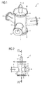
- the FIG. 1 shows a perspective view of the valve 1.
- the valve 1 comprises a valve housing 2, which is formed substantially cylindrical about a rotation axis 3.
- a supply line 4 To the valve housing 2, a supply line 4, a turbine outlet line 5 and a diversion output line 6 is arranged. Both the supply line 4 and the turbine output line 5 and the diversion output line 6 are designed substantially as tubes with a suitable diameter.
- the valve housing 2 comprises at a lower end 7 a lower valve cover 8. At an upper end 9, an upper valve cover 10 is arranged.
- the supply line 4, the turbine outlet line 5 and the diversion output line 6 are arranged at 120 ° to each other.
- the supply line 4, the turbine output line 5 and the bypass output line 6 can be arranged at an angle different from 120 °.
- a valve body 11 is arranged, which is movable on the one hand in the direction of the rotation axis 3 via a drive, not shown, and on the other hand via a drive, also not shown about the rotation axis 3 can be rotatably moved.
- FIG. 2 is a side view of the valve 1 can be seen.
- the valve body 11 is arranged under a spring force transducer 12. Between the Federkraftaufsacrificing 12 and the upper valve cover 10, a spring not shown is arranged.
- the valve body 11 is brought with the Federkraftaufsacrificing 12 in a first position, in which a coming on the supply line 4 steam substantially completely to Turbine output line 5 is realized via a valve body 11 located in the control valve line 13.
- the spring force transducer 12 absorbs the spring forces, which thus do not load on the valve body 11. Thereby, the valve body 11 can be rotated about the axis.
- the pulling up against the spring forces by a drive that pulls not on the axis, but on a hollow shaft of the spring force transducer 12.
- the control valve line 13 is designed such that in the first position, a fluidic connection between the supply line 4 and the turbine output line 5 is formed.
- valve 1 shows the valve 1 in an open position.
- FIG. 4 is a cross-sectional view of the valve 1 along the line IV FIG. 2 to see.
- the valve body 11 is moved for the purpose of rapid closure linearly via drive motors, not shown, or rotated about the rotation axis 3, to control the mass flow from the supply line 4 to the turbine outlet line 5.
- FIG. 5 is a sectional view through the valve 1 along the line V according to FIG. 3 to see.
- the valve body 11 has a bypass valve line 14, which diverts the steam in the second position from the supply line 4 in the diversion output line 6.
- the bypass valve line 14 has substantially the same cross section as the supply line 4, the turbine output line 5 or the diversion output line 6.
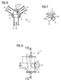
- FIG. 6 is a section of the valve 1 along the line VI FIG. 3 to see.
- the valve body 11 has a control valve line 13, which produces a fluidic connection in the first position between the supply line 4 and the turbine outlet line 5.
- the control valve line cross section 15 is changed by rotating the valve body 11 about the rotation axis 3.
- the valve body 11 further has a first pressure bore 16. In the in FIG. 6 shown position of the valve body 11 creates a fluidic connection between the supply line 4 and the diversion output line 6 through the first pressure bore 16. A portion of the mass flow is thereby not led to the steam turbine via the turbine output line 5, but in the diversion via the diversion output line. 6
- FIG. 12 is essentially identical to the FIG. 6 , however, shows a changed position of the valve body 11.
- the in FIG. 12 shown position of the valve body 11 is opposite to the position of the valve body 11 in the FIG. 6 rotated slightly counterclockwise, so that via the first pressure bore 16 now no fluidic connection between the supply line 4 and the diversion output line 6 takes place.
- the valve body 11 is designed such that the control valve line 13 is designed such that the free passage area of the steam through the control valve line 13 in the positions of the valve body 11 in accordance FIG. 12 and FIG. 6 is equal to.
- valve body 11 has a second pressure bore 19, which as seen FIG. 6 and FIG. 12 can be seen, is arranged in a certain angular range after the first pressure bore 16.
- the pressure holes 16, 19 can be replaced by a suitable, for. B. elongated opening replaced and set arbitrarily.
- FIG. 7 is an enlarged view of the pressure holes 16 and 19 FIG. 6 shown.
- position of the valve body 11 shows a complete opening of the first pressure bore 16 and a partial opening of the second pressure bore 19th
- valve In the FIGS. 8 . 9, 10 and 11 the valve is shown in the second position. In this second position creates a fluidic connection between the supply line 4 and the bypass outlet line 6. This is done by the spring, not shown abruptly the valve body 11 moves vertically downwards. Thereby, the control valve line 13 is completely removed from the steam supply in the supply line 4 and instead the bypass valve line 14 is positioned in front of the supply line 4, that the steam from the supply line 4 is completely diverted into the diversion output line 6. A passage of steam from the supply line 4 in the turbine output line 5 is thus prevented.
- FIG. 11 shown position of the valve body 11 shows a section through the valve 1 along the line IX FIG. 9
- the FIG. 10 shows a section along the valve 1 along the line VIII FIG. 8 ,
Landscapes
- Engineering & Computer Science (AREA)
- General Engineering & Computer Science (AREA)
- Mechanical Engineering (AREA)
- Control Of Turbines (AREA)
Claims (6)
- Robinet (1),
comprenant un conduit (4) d'admission, un conduit (5) de sortie de turbine et un conduit (6) de sortie de dérivation ainsi qu'un obturateur (11),
qui est constitué de manière
à ce que, dans une première position, une communication fluidique se crée entre le conduit (4) d'admission et le conduit (5) de sortie de turbine et,
dans une deuxième position, une communication fluidique se crée entre le conduit (4) d'admission et le conduit (6) de sortie de dérivation,
dans lequel, l'obturateur (11) est cylindrique et un passage entre la première position et la deuxième position s'effectue par un déplacement linéaire de l'obturateur (11) dans la direction de l'axe (3) de rotation,
dans lequel l'obturateur (11) a, dans la première position, un conduit (13) de robinet de réglage ayant une section (15) transversale de conduit de robinet de réglage pour la communication fluidique entre le conduit (4) d'admission et le conduit (5) de sortie de turbine,
dans lequel la section (15) transversale de conduit de robinet de réglage peut être modifiée en faisant tourner l'obturateur (11),
dans lequel le conduit (4) d'admission et le conduit (5) de sorite de turbine et le conduit (6) de sortie de dérivation sont disposés sensiblement dans un plan,
dans lequel l'obturateur (11) a un premier trou (16) de refoulement,
qui ménage une communication fluidique entre le conduit (4) d'admission et le conduit (6) de sortie de dérivation dans la première position. - Robinet (1) suivant la revendication 1,
dans lequel l'obturateur (11) a un deuxième trou (19) de refoulement qui ménage, dans la première position, en continuant à faire tourner l'obturateur (11), une autre communication fluidique entre le conduit (4) d'admission et le conduit (6) de sortie de dérivation. - Robinet (1) suivant l'une des revendications précédentes,
dans lequel l'obturateur (11) est disposé dans un corps (2) cylindrique de robinet. - Robinet (1) suivant la revendication 3,
dans lequel le conduit (4) d'admission, le conduit (5) de sortie de turbine et le conduit (6) de sortie de dérivation débouchent dans le corps (2) de robinet. - Robinet (1) suivant l'une des revendications 3 ou 4,
dans lequel, dans le corps (2) de robinet, est monté un ressort,
de manière à retenir l'obturateur (11) dans la première position à l'encontre de la force du ressort. - Robinet (1) suivant la revendication 5,
dans lequel le passage de la première position à la deuxième position s'effectue par la force du ressort.
Priority Applications (2)
| Application Number | Priority Date | Filing Date | Title |
|---|---|---|---|
| EP10755154.1A EP2478276B1 (fr) | 2009-09-18 | 2010-09-17 | Soupape pour turbomachine |
| PL10755154T PL2478276T3 (pl) | 2009-09-18 | 2010-09-17 | Zawór dla maszyny przepływowej |
Applications Claiming Priority (3)
| Application Number | Priority Date | Filing Date | Title |
|---|---|---|---|
| EP09011931A EP2299153A1 (fr) | 2009-09-18 | 2009-09-18 | Soupape pour turbomachine |
| EP10755154.1A EP2478276B1 (fr) | 2009-09-18 | 2010-09-17 | Soupape pour turbomachine |
| PCT/EP2010/063708 WO2011033069A1 (fr) | 2009-09-18 | 2010-09-17 | Vanne pour une turbomachine |
Publications (2)
| Publication Number | Publication Date |
|---|---|
| EP2478276A1 EP2478276A1 (fr) | 2012-07-25 |
| EP2478276B1 true EP2478276B1 (fr) | 2013-07-31 |
Family
ID=41652930
Family Applications (2)
| Application Number | Title | Priority Date | Filing Date |
|---|---|---|---|
| EP09011931A Withdrawn EP2299153A1 (fr) | 2009-09-18 | 2009-09-18 | Soupape pour turbomachine |
| EP10755154.1A Not-in-force EP2478276B1 (fr) | 2009-09-18 | 2010-09-17 | Soupape pour turbomachine |
Family Applications Before (1)
| Application Number | Title | Priority Date | Filing Date |
|---|---|---|---|
| EP09011931A Withdrawn EP2299153A1 (fr) | 2009-09-18 | 2009-09-18 | Soupape pour turbomachine |
Country Status (4)
| Country | Link |
|---|---|
| EP (2) | EP2299153A1 (fr) |
| CN (1) | CN102549323B (fr) |
| PL (1) | PL2478276T3 (fr) |
| WO (1) | WO2011033069A1 (fr) |
Families Citing this family (4)
| Publication number | Priority date | Publication date | Assignee | Title |
|---|---|---|---|---|
| ES2709098T3 (es) * | 2013-07-15 | 2019-04-15 | Abn Pipe Systems S L U | Red de evacuación de aguas residuales |
| BE1022707B1 (nl) * | 2015-02-11 | 2016-08-19 | Atlas Copco Airpower Naamloze Vennootschap | Werkwijze en inrichting voor het regelen van de olietemperatuur van een oliegeïnjecteerde compressorinstallatie of vacuümpomp en klep toegepast in dergelijke inrichting |
| CN106870771A (zh) * | 2015-12-11 | 2017-06-20 | 飞翼股份有限公司 | 一种输送充填料用手动换向阀 |
| DE102020115516A1 (de) * | 2020-06-10 | 2021-12-16 | Woco Industrietechnik Gmbh | Wegeventil und Ventilkäfig für ein Wegeventil |
Family Cites Families (12)
| Publication number | Priority date | Publication date | Assignee | Title |
|---|---|---|---|---|
| FR612647A (fr) * | 1925-03-20 | 1926-10-27 | Brown | Dispositif pour la marche à vide de turbines à contre-pression |
| US1807085A (en) * | 1928-07-25 | 1931-05-26 | Tridex Corp | Two-way valve |
| US2752944A (en) * | 1953-03-31 | 1956-07-03 | Read Standard Corp | Diverting valve |
| FR1556627A (fr) * | 1968-02-29 | 1969-02-07 | ||
| DE2038085A1 (de) * | 1970-07-31 | 1972-02-10 | Centra Buerkle Kg Albert | Dreiweg-Mischhahn |
| NL9002862A (nl) * | 1990-12-21 | 1992-07-16 | Necam Bv | Inrichting voor het inspuiten van een gasvormige brandstof in een verbrandingsmotor, alsmede doseermiddel en drukregelklep daarvoor. |
| GB9312843D0 (en) * | 1993-06-22 | 1993-08-04 | Spirax Sarco Ltd | Condensate traps |
| DE4326916A1 (de) * | 1993-08-11 | 1995-02-16 | Buehler Gmbh | Kükenweiche |
| FR2736701B1 (fr) * | 1995-07-12 | 1999-01-15 | Raux Regis | Vanne demontable pour la distribution de produits homogenes ou heterogenes a faible ou a forte viscosite |
| CN2402891Y (zh) * | 1999-12-29 | 2000-10-25 | 化学工业部上海化工研究院 | 复式三通旋塞阀 |
| CN2426547Y (zh) * | 2000-05-12 | 2001-04-11 | 张泰吉 | 压力输送分路阀 |
| EP1637783B1 (fr) * | 2004-09-20 | 2012-08-01 | Siemens Aktiengesellschaft | Combinaison de soupape pour turbine à vapeur avec une soupape à fermeture rapide et une soupape de régulation |
-
2009
- 2009-09-18 EP EP09011931A patent/EP2299153A1/fr not_active Withdrawn
-
2010
- 2010-09-17 EP EP10755154.1A patent/EP2478276B1/fr not_active Not-in-force
- 2010-09-17 WO PCT/EP2010/063708 patent/WO2011033069A1/fr not_active Ceased
- 2010-09-17 PL PL10755154T patent/PL2478276T3/pl unknown
- 2010-09-17 CN CN201080041656.8A patent/CN102549323B/zh not_active Expired - Fee Related
Also Published As
| Publication number | Publication date |
|---|---|
| EP2299153A1 (fr) | 2011-03-23 |
| CN102549323A (zh) | 2012-07-04 |
| EP2478276A1 (fr) | 2012-07-25 |
| PL2478276T3 (pl) | 2013-12-31 |
| CN102549323B (zh) | 2014-01-29 |
| WO2011033069A1 (fr) | 2011-03-24 |
Similar Documents
| Publication | Publication Date | Title |
|---|---|---|
| DE2260552C3 (de) | Leitschaufelkranz für eine Gasturbine | |
| DE102013212560A1 (de) | Zylinder und Zylinderanordnung mit einem derartigen Zylinder | |
| EP2478276B1 (fr) | Soupape pour turbomachine | |
| DE2150317C3 (de) | Kombiniertes Schnellschluß- und Regelventil | |
| DE102018123573B4 (de) | Druckausgleichsklappenbaugruppe | |
| EP2000632A1 (fr) | Turbine dotée d'un boîtier d'entrée compact grâce à une soupape de réglage interne | |
| EP3227550B1 (fr) | Turbomachine hydraulique | |
| EP1637783B1 (fr) | Combinaison de soupape pour turbine à vapeur avec une soupape à fermeture rapide et une soupape de régulation | |
| DE102014201502A1 (de) | Dampfturbine | |
| DE102013216790A1 (de) | Schaltarmaturanordnung | |
| DE102009004286A1 (de) | Hydraulische Steuerschaltung | |
| EP4377574B1 (fr) | Soupape de sécurité | |
| EP1757817B1 (fr) | Arrangement de valve pour contrôler une soupape à fermeture rapide de turbine à gaz ou à vapeur | |
| DE102011012305B4 (de) | Hydraulische Stellanordnung | |
| EP2382410B1 (fr) | Soupape à fermeture rapide | |
| CH625030A5 (fr) | ||
| DE102015210274A1 (de) | Mehrwegeventil, insbesondere ein 6/2-Wegeventil und Mehrwegeventilanordnung | |
| DE102015222745A1 (de) | Ventil mit Stromregel- und Druckbegrenzungsfunktion | |
| DE2708642C3 (de) | Dampfleitung | |
| EP2988037A1 (fr) | Vanne pour une conduite de décharge | |
| DE2740761C3 (de) | Dampfleitung | |
| DE102010041704A1 (de) | Regelventil zur Regelung eines Volumenstromes | |
| DE102018126930B4 (de) | Verstellvorrichtung und ein Verfahren zur Verstellung der Leitschaufeln eines Verdichters eines Gasturbinentriebwerks | |
| DE2818690C2 (de) | Ventil für Sicherheitszwecke | |
| EP2781690A1 (fr) | Soupape pour une turbine à vapeur |
Legal Events
| Date | Code | Title | Description |
|---|---|---|---|
| PUAI | Public reference made under article 153(3) epc to a published international application that has entered the european phase |
Free format text: ORIGINAL CODE: 0009012 |
|
| 17P | Request for examination filed |
Effective date: 20120209 |
|
| AK | Designated contracting states |
Kind code of ref document: A1 Designated state(s): AL AT BE BG CH CY CZ DE DK EE ES FI FR GB GR HR HU IE IS IT LI LT LU LV MC MK MT NL NO PL PT RO SE SI SK SM TR |
|
| DAX | Request for extension of the european patent (deleted) | ||
| GRAP | Despatch of communication of intention to grant a patent |
Free format text: ORIGINAL CODE: EPIDOSNIGR1 |
|
| RAP1 | Party data changed (applicant data changed or rights of an application transferred) |
Owner name: SIEMENS AKTIENGESELLSCHAFT |
|
| GRAS | Grant fee paid |
Free format text: ORIGINAL CODE: EPIDOSNIGR3 |
|
| GRAA | (expected) grant |
Free format text: ORIGINAL CODE: 0009210 |
|
| AK | Designated contracting states |
Kind code of ref document: B1 Designated state(s): AL AT BE BG CH CY CZ DE DK EE ES FI FR GB GR HR HU IE IS IT LI LT LU LV MC MK MT NL NO PL PT RO SE SI SK SM TR |
|
| REG | Reference to a national code |
Ref country code: GB Ref legal event code: FG4D Free format text: NOT ENGLISH Ref country code: CH Ref legal event code: EP |
|
| REG | Reference to a national code |
Ref country code: AT Ref legal event code: REF Ref document number: 624859 Country of ref document: AT Kind code of ref document: T Effective date: 20130815 |
|
| REG | Reference to a national code |
Ref country code: IE Ref legal event code: FG4D Free format text: LANGUAGE OF EP DOCUMENT: GERMAN |
|
| REG | Reference to a national code |
Ref country code: CH Ref legal event code: NV Representative=s name: SIEMENS SCHWEIZ AG, CH |
|
| REG | Reference to a national code |
Ref country code: DE Ref legal event code: R096 Ref document number: 502010004232 Country of ref document: DE Effective date: 20130926 |
|
| REG | Reference to a national code |
Ref country code: NL Ref legal event code: VDEP Effective date: 20130731 |
|
| REG | Reference to a national code |
Ref country code: LT Ref legal event code: MG4D |
|
| REG | Reference to a national code |
Ref country code: PL Ref legal event code: T3 |
|
| PG25 | Lapsed in a contracting state [announced via postgrant information from national office to epo] |
Ref country code: HR Free format text: LAPSE BECAUSE OF FAILURE TO SUBMIT A TRANSLATION OF THE DESCRIPTION OR TO PAY THE FEE WITHIN THE PRESCRIBED TIME-LIMIT Effective date: 20130731 Ref country code: SE Free format text: LAPSE BECAUSE OF FAILURE TO SUBMIT A TRANSLATION OF THE DESCRIPTION OR TO PAY THE FEE WITHIN THE PRESCRIBED TIME-LIMIT Effective date: 20130731 Ref country code: LT Free format text: LAPSE BECAUSE OF FAILURE TO SUBMIT A TRANSLATION OF THE DESCRIPTION OR TO PAY THE FEE WITHIN THE PRESCRIBED TIME-LIMIT Effective date: 20130731 Ref country code: CY Free format text: LAPSE BECAUSE OF FAILURE TO SUBMIT A TRANSLATION OF THE DESCRIPTION OR TO PAY THE FEE WITHIN THE PRESCRIBED TIME-LIMIT Effective date: 20130904 Ref country code: NO Free format text: LAPSE BECAUSE OF FAILURE TO SUBMIT A TRANSLATION OF THE DESCRIPTION OR TO PAY THE FEE WITHIN THE PRESCRIBED TIME-LIMIT Effective date: 20131031 Ref country code: PT Free format text: LAPSE BECAUSE OF FAILURE TO SUBMIT A TRANSLATION OF THE DESCRIPTION OR TO PAY THE FEE WITHIN THE PRESCRIBED TIME-LIMIT Effective date: 20131202 Ref country code: IS Free format text: LAPSE BECAUSE OF FAILURE TO SUBMIT A TRANSLATION OF THE DESCRIPTION OR TO PAY THE FEE WITHIN THE PRESCRIBED TIME-LIMIT Effective date: 20131130 |
|
| PG25 | Lapsed in a contracting state [announced via postgrant information from national office to epo] |
Ref country code: LV Free format text: LAPSE BECAUSE OF FAILURE TO SUBMIT A TRANSLATION OF THE DESCRIPTION OR TO PAY THE FEE WITHIN THE PRESCRIBED TIME-LIMIT Effective date: 20130731 Ref country code: FI Free format text: LAPSE BECAUSE OF FAILURE TO SUBMIT A TRANSLATION OF THE DESCRIPTION OR TO PAY THE FEE WITHIN THE PRESCRIBED TIME-LIMIT Effective date: 20130731 Ref country code: GR Free format text: LAPSE BECAUSE OF FAILURE TO SUBMIT A TRANSLATION OF THE DESCRIPTION OR TO PAY THE FEE WITHIN THE PRESCRIBED TIME-LIMIT Effective date: 20131101 Ref country code: SI Free format text: LAPSE BECAUSE OF FAILURE TO SUBMIT A TRANSLATION OF THE DESCRIPTION OR TO PAY THE FEE WITHIN THE PRESCRIBED TIME-LIMIT Effective date: 20130731 Ref country code: NL Free format text: LAPSE BECAUSE OF FAILURE TO SUBMIT A TRANSLATION OF THE DESCRIPTION OR TO PAY THE FEE WITHIN THE PRESCRIBED TIME-LIMIT Effective date: 20130731 |
|
| BERE | Be: lapsed |
Owner name: SIEMENS A.G. Effective date: 20130930 |
|
| PG25 | Lapsed in a contracting state [announced via postgrant information from national office to epo] |
Ref country code: CY Free format text: LAPSE BECAUSE OF FAILURE TO SUBMIT A TRANSLATION OF THE DESCRIPTION OR TO PAY THE FEE WITHIN THE PRESCRIBED TIME-LIMIT Effective date: 20130731 |
|
| PG25 | Lapsed in a contracting state [announced via postgrant information from national office to epo] |
Ref country code: DK Free format text: LAPSE BECAUSE OF FAILURE TO SUBMIT A TRANSLATION OF THE DESCRIPTION OR TO PAY THE FEE WITHIN THE PRESCRIBED TIME-LIMIT Effective date: 20130731 Ref country code: MC Free format text: LAPSE BECAUSE OF FAILURE TO SUBMIT A TRANSLATION OF THE DESCRIPTION OR TO PAY THE FEE WITHIN THE PRESCRIBED TIME-LIMIT Effective date: 20130731 Ref country code: SK Free format text: LAPSE BECAUSE OF FAILURE TO SUBMIT A TRANSLATION OF THE DESCRIPTION OR TO PAY THE FEE WITHIN THE PRESCRIBED TIME-LIMIT Effective date: 20130731 Ref country code: RO Free format text: LAPSE BECAUSE OF FAILURE TO SUBMIT A TRANSLATION OF THE DESCRIPTION OR TO PAY THE FEE WITHIN THE PRESCRIBED TIME-LIMIT Effective date: 20130731 Ref country code: EE Free format text: LAPSE BECAUSE OF FAILURE TO SUBMIT A TRANSLATION OF THE DESCRIPTION OR TO PAY THE FEE WITHIN THE PRESCRIBED TIME-LIMIT Effective date: 20130731 |
|
| PG25 | Lapsed in a contracting state [announced via postgrant information from national office to epo] |
Ref country code: ES Free format text: LAPSE BECAUSE OF FAILURE TO SUBMIT A TRANSLATION OF THE DESCRIPTION OR TO PAY THE FEE WITHIN THE PRESCRIBED TIME-LIMIT Effective date: 20130731 |
|
| PLBE | No opposition filed within time limit |
Free format text: ORIGINAL CODE: 0009261 |
|
| STAA | Information on the status of an ep patent application or granted ep patent |
Free format text: STATUS: NO OPPOSITION FILED WITHIN TIME LIMIT |
|
| REG | Reference to a national code |
Ref country code: IE Ref legal event code: MM4A |
|
| 26N | No opposition filed |
Effective date: 20140502 |
|
| PG25 | Lapsed in a contracting state [announced via postgrant information from national office to epo] |
Ref country code: BE Free format text: LAPSE BECAUSE OF NON-PAYMENT OF DUE FEES Effective date: 20130930 Ref country code: IE Free format text: LAPSE BECAUSE OF NON-PAYMENT OF DUE FEES Effective date: 20130917 |
|
| REG | Reference to a national code |
Ref country code: DE Ref legal event code: R097 Ref document number: 502010004232 Country of ref document: DE Effective date: 20140502 |
|
| PG25 | Lapsed in a contracting state [announced via postgrant information from national office to epo] |
Ref country code: SM Free format text: LAPSE BECAUSE OF FAILURE TO SUBMIT A TRANSLATION OF THE DESCRIPTION OR TO PAY THE FEE WITHIN THE PRESCRIBED TIME-LIMIT Effective date: 20130731 |
|
| PG25 | Lapsed in a contracting state [announced via postgrant information from national office to epo] |
Ref country code: MT Free format text: LAPSE BECAUSE OF FAILURE TO SUBMIT A TRANSLATION OF THE DESCRIPTION OR TO PAY THE FEE WITHIN THE PRESCRIBED TIME-LIMIT Effective date: 20130731 Ref country code: TR Free format text: LAPSE BECAUSE OF FAILURE TO SUBMIT A TRANSLATION OF THE DESCRIPTION OR TO PAY THE FEE WITHIN THE PRESCRIBED TIME-LIMIT Effective date: 20130731 |
|
| PG25 | Lapsed in a contracting state [announced via postgrant information from national office to epo] |
Ref country code: BG Free format text: LAPSE BECAUSE OF FAILURE TO SUBMIT A TRANSLATION OF THE DESCRIPTION OR TO PAY THE FEE WITHIN THE PRESCRIBED TIME-LIMIT Effective date: 20130731 Ref country code: HU Free format text: LAPSE BECAUSE OF FAILURE TO SUBMIT A TRANSLATION OF THE DESCRIPTION OR TO PAY THE FEE WITHIN THE PRESCRIBED TIME-LIMIT; INVALID AB INITIO Effective date: 20100917 Ref country code: LU Free format text: LAPSE BECAUSE OF NON-PAYMENT OF DUE FEES Effective date: 20130917 Ref country code: MK Free format text: LAPSE BECAUSE OF FAILURE TO SUBMIT A TRANSLATION OF THE DESCRIPTION OR TO PAY THE FEE WITHIN THE PRESCRIBED TIME-LIMIT Effective date: 20130731 |
|
| REG | Reference to a national code |
Ref country code: FR Ref legal event code: PLFP Year of fee payment: 7 |
|
| REG | Reference to a national code |
Ref country code: AT Ref legal event code: MM01 Ref document number: 624859 Country of ref document: AT Kind code of ref document: T Effective date: 20150917 |
|
| PG25 | Lapsed in a contracting state [announced via postgrant information from national office to epo] |
Ref country code: AT Free format text: LAPSE BECAUSE OF NON-PAYMENT OF DUE FEES Effective date: 20150917 |
|
| REG | Reference to a national code |
Ref country code: FR Ref legal event code: PLFP Year of fee payment: 8 |
|
| REG | Reference to a national code |
Ref country code: CH Ref legal event code: PCOW Free format text: NEW ADDRESS: WERNER-VON-SIEMENS-STRASSE 1, 80333 MUENCHEN (DE) |
|
| PGFP | Annual fee paid to national office [announced via postgrant information from national office to epo] |
Ref country code: FR Payment date: 20170918 Year of fee payment: 8 Ref country code: IT Payment date: 20170927 Year of fee payment: 8 Ref country code: GB Payment date: 20170912 Year of fee payment: 8 Ref country code: CZ Payment date: 20170915 Year of fee payment: 8 |
|
| PGFP | Annual fee paid to national office [announced via postgrant information from national office to epo] |
Ref country code: PL Payment date: 20170823 Year of fee payment: 8 |
|
| PGFP | Annual fee paid to national office [announced via postgrant information from national office to epo] |
Ref country code: CH Payment date: 20171207 Year of fee payment: 8 |
|
| PGFP | Annual fee paid to national office [announced via postgrant information from national office to epo] |
Ref country code: DE Payment date: 20180110 Year of fee payment: 8 |
|
| PG25 | Lapsed in a contracting state [announced via postgrant information from national office to epo] |
Ref country code: AL Free format text: LAPSE BECAUSE OF FAILURE TO SUBMIT A TRANSLATION OF THE DESCRIPTION OR TO PAY THE FEE WITHIN THE PRESCRIBED TIME-LIMIT Effective date: 20130731 |
|
| REG | Reference to a national code |
Ref country code: DE Ref legal event code: R119 Ref document number: 502010004232 Country of ref document: DE |
|
| PG25 | Lapsed in a contracting state [announced via postgrant information from national office to epo] |
Ref country code: CZ Free format text: LAPSE BECAUSE OF NON-PAYMENT OF DUE FEES Effective date: 20180917 |
|
| REG | Reference to a national code |
Ref country code: CH Ref legal event code: PL |
|
| GBPC | Gb: european patent ceased through non-payment of renewal fee |
Effective date: 20180917 |
|
| PG25 | Lapsed in a contracting state [announced via postgrant information from national office to epo] |
Ref country code: IT Free format text: LAPSE BECAUSE OF NON-PAYMENT OF DUE FEES Effective date: 20180917 Ref country code: DE Free format text: LAPSE BECAUSE OF NON-PAYMENT OF DUE FEES Effective date: 20190402 |
|
| PG25 | Lapsed in a contracting state [announced via postgrant information from national office to epo] |
Ref country code: FR Free format text: LAPSE BECAUSE OF NON-PAYMENT OF DUE FEES Effective date: 20180930 Ref country code: CH Free format text: LAPSE BECAUSE OF NON-PAYMENT OF DUE FEES Effective date: 20180930 Ref country code: LI Free format text: LAPSE BECAUSE OF NON-PAYMENT OF DUE FEES Effective date: 20180930 |
|
| PG25 | Lapsed in a contracting state [announced via postgrant information from national office to epo] |
Ref country code: GB Free format text: LAPSE BECAUSE OF NON-PAYMENT OF DUE FEES Effective date: 20180917 |
|
| PG25 | Lapsed in a contracting state [announced via postgrant information from national office to epo] |
Ref country code: PL Free format text: LAPSE BECAUSE OF NON-PAYMENT OF DUE FEES Effective date: 20180917 |