EP2478826A1 - Système d'endoscope - Google Patents
Système d'endoscope Download PDFInfo
- Publication number
- EP2478826A1 EP2478826A1 EP11196079A EP11196079A EP2478826A1 EP 2478826 A1 EP2478826 A1 EP 2478826A1 EP 11196079 A EP11196079 A EP 11196079A EP 11196079 A EP11196079 A EP 11196079A EP 2478826 A1 EP2478826 A1 EP 2478826A1
- Authority
- EP
- European Patent Office
- Prior art keywords
- fluorescence
- image
- light
- images
- autofluorescence
- Prior art date
- Legal status (The legal status is an assumption and is not a legal conclusion. Google has not performed a legal analysis and makes no representation as to the accuracy of the status listed.)
- Withdrawn
Links
- 230000005284 excitation Effects 0.000 claims abstract description 93
- 238000000034 method Methods 0.000 claims abstract description 19
- 230000008569 process Effects 0.000 claims abstract description 18
- 238000012545 processing Methods 0.000 claims description 90
- 238000012937 correction Methods 0.000 claims description 19
- 230000003902 lesion Effects 0.000 abstract description 44
- 238000012327 Endoscopic diagnosis Methods 0.000 abstract 1
- 238000002073 fluorescence micrograph Methods 0.000 description 68
- 210000001519 tissue Anatomy 0.000 description 23
- 238000003384 imaging method Methods 0.000 description 19
- 239000013307 optical fiber Substances 0.000 description 17
- 230000003595 spectral effect Effects 0.000 description 10
- 238000013459 approach Methods 0.000 description 8
- 238000005452 bending Methods 0.000 description 7
- 238000006243 chemical reaction Methods 0.000 description 7
- 230000000875 corresponding effect Effects 0.000 description 7
- 238000005286 illumination Methods 0.000 description 7
- XLYOFNOQVPJJNP-UHFFFAOYSA-N water Substances O XLYOFNOQVPJJNP-UHFFFAOYSA-N 0.000 description 7
- 238000010586 diagram Methods 0.000 description 5
- 229930027945 nicotinamide-adenine dinucleotide Natural products 0.000 description 5
- 230000003287 optical effect Effects 0.000 description 5
- 230000000644 propagated effect Effects 0.000 description 5
- 238000003780 insertion Methods 0.000 description 4
- 230000037431 insertion Effects 0.000 description 4
- ACFIXJIJDZMPPO-NNYOXOHSSA-N NADPH Chemical compound C1=CCC(C(=O)N)=CN1[C@H]1[C@H](O)[C@H](O)[C@@H](COP(O)(=O)OP(O)(=O)OC[C@@H]2[C@H]([C@@H](OP(O)(O)=O)[C@@H](O2)N2C3=NC=NC(N)=C3N=C2)O)O1 ACFIXJIJDZMPPO-NNYOXOHSSA-N 0.000 description 3
- 210000004204 blood vessel Anatomy 0.000 description 3
- 230000002596 correlated effect Effects 0.000 description 3
- 238000003745 diagnosis Methods 0.000 description 3
- 238000003702 image correction Methods 0.000 description 3
- BOPGDPNILDQYTO-NNYOXOHSSA-N nicotinamide-adenine dinucleotide Chemical compound C1=CCC(C(=O)N)=CN1[C@H]1[C@H](O)[C@H](O)[C@@H](COP(O)(=O)OP(O)(=O)OC[C@@H]2[C@H]([C@@H](O)[C@@H](O2)N2C3=NC=NC(N)=C3N=C2)O)O1 BOPGDPNILDQYTO-NNYOXOHSSA-N 0.000 description 3
- 238000005375 photometry Methods 0.000 description 3
- 238000005070 sampling Methods 0.000 description 3
- 230000003321 amplification Effects 0.000 description 2
- 230000003247 decreasing effect Effects 0.000 description 2
- 238000001514 detection method Methods 0.000 description 2
- VWWQXMAJTJZDQX-UYBVJOGSSA-N flavin adenine dinucleotide Chemical compound C1=NC2=C(N)N=CN=C2N1[C@@H]([C@H](O)[C@@H]1O)O[C@@H]1CO[P@](O)(=O)O[P@@](O)(=O)OC[C@@H](O)[C@@H](O)[C@@H](O)CN1C2=NC(=O)NC(=O)C2=NC2=C1C=C(C)C(C)=C2 VWWQXMAJTJZDQX-UYBVJOGSSA-N 0.000 description 2
- 235000019162 flavin adenine dinucleotide Nutrition 0.000 description 2
- 239000011714 flavin adenine dinucleotide Substances 0.000 description 2
- 229940093632 flavin-adenine dinucleotide Drugs 0.000 description 2
- 230000006870 function Effects 0.000 description 2
- 210000004400 mucous membrane Anatomy 0.000 description 2
- 238000003199 nucleic acid amplification method Methods 0.000 description 2
- 150000004032 porphyrins Chemical class 0.000 description 2
- 230000035945 sensitivity Effects 0.000 description 2
- 238000001228 spectrum Methods 0.000 description 2
- 229910052724 xenon Inorganic materials 0.000 description 2
- FHNFHKCVQCLJFQ-UHFFFAOYSA-N xenon atom Chemical compound [Xe] FHNFHKCVQCLJFQ-UHFFFAOYSA-N 0.000 description 2
- 235000005811 Viola adunca Nutrition 0.000 description 1
- 240000009038 Viola odorata Species 0.000 description 1
- 235000013487 Viola odorata Nutrition 0.000 description 1
- 235000002254 Viola papilionacea Nutrition 0.000 description 1
- 230000000903 blocking effect Effects 0.000 description 1
- 230000008859 change Effects 0.000 description 1
- 230000000112 colonic effect Effects 0.000 description 1
- 239000003086 colorant Substances 0.000 description 1
- 239000002131 composite material Substances 0.000 description 1
- 230000001276 controlling effect Effects 0.000 description 1
- 239000006059 cover glass Substances 0.000 description 1
- 230000002708 enhancing effect Effects 0.000 description 1
- 238000000799 fluorescence microscopy Methods 0.000 description 1
- 238000010348 incorporation Methods 0.000 description 1
- 238000002347 injection Methods 0.000 description 1
- 239000007924 injection Substances 0.000 description 1
- 230000001678 irradiating effect Effects 0.000 description 1
- 239000011159 matrix material Substances 0.000 description 1
- 238000012986 modification Methods 0.000 description 1
- 230000004048 modification Effects 0.000 description 1
- 210000004877 mucosa Anatomy 0.000 description 1
Images

Classifications
-
- A—HUMAN NECESSITIES
- A61—MEDICAL OR VETERINARY SCIENCE; HYGIENE
- A61B—DIAGNOSIS; SURGERY; IDENTIFICATION
- A61B1/00—Instruments for performing medical examinations of the interior of cavities or tubes of the body by visual or photographical inspection, e.g. endoscopes; Illuminating arrangements therefor
- A61B1/06—Instruments for performing medical examinations of the interior of cavities or tubes of the body by visual or photographical inspection, e.g. endoscopes; Illuminating arrangements therefor with illuminating arrangements
- A61B1/0638—Instruments for performing medical examinations of the interior of cavities or tubes of the body by visual or photographical inspection, e.g. endoscopes; Illuminating arrangements therefor with illuminating arrangements providing two or more wavelengths
-
- A—HUMAN NECESSITIES
- A61—MEDICAL OR VETERINARY SCIENCE; HYGIENE
- A61B—DIAGNOSIS; SURGERY; IDENTIFICATION
- A61B1/00—Instruments for performing medical examinations of the interior of cavities or tubes of the body by visual or photographical inspection, e.g. endoscopes; Illuminating arrangements therefor
- A61B1/00002—Operational features of endoscopes
- A61B1/00004—Operational features of endoscopes characterised by electronic signal processing
- A61B1/00009—Operational features of endoscopes characterised by electronic signal processing of image signals during a use of endoscope
- A61B1/000094—Operational features of endoscopes characterised by electronic signal processing of image signals during a use of endoscope extracting biological structures
-
- A—HUMAN NECESSITIES
- A61—MEDICAL OR VETERINARY SCIENCE; HYGIENE
- A61B—DIAGNOSIS; SURGERY; IDENTIFICATION
- A61B1/00—Instruments for performing medical examinations of the interior of cavities or tubes of the body by visual or photographical inspection, e.g. endoscopes; Illuminating arrangements therefor
- A61B1/00002—Operational features of endoscopes
- A61B1/00004—Operational features of endoscopes characterised by electronic signal processing
- A61B1/00009—Operational features of endoscopes characterised by electronic signal processing of image signals during a use of endoscope
- A61B1/000095—Operational features of endoscopes characterised by electronic signal processing of image signals during a use of endoscope for image enhancement
-
- A—HUMAN NECESSITIES
- A61—MEDICAL OR VETERINARY SCIENCE; HYGIENE
- A61B—DIAGNOSIS; SURGERY; IDENTIFICATION
- A61B1/00—Instruments for performing medical examinations of the interior of cavities or tubes of the body by visual or photographical inspection, e.g. endoscopes; Illuminating arrangements therefor
- A61B1/00163—Optical arrangements
- A61B1/00186—Optical arrangements with imaging filters
-
- A—HUMAN NECESSITIES
- A61—MEDICAL OR VETERINARY SCIENCE; HYGIENE
- A61B—DIAGNOSIS; SURGERY; IDENTIFICATION
- A61B1/00—Instruments for performing medical examinations of the interior of cavities or tubes of the body by visual or photographical inspection, e.g. endoscopes; Illuminating arrangements therefor
- A61B1/04—Instruments for performing medical examinations of the interior of cavities or tubes of the body by visual or photographical inspection, e.g. endoscopes; Illuminating arrangements therefor combined with photographic or television appliances
- A61B1/043—Instruments for performing medical examinations of the interior of cavities or tubes of the body by visual or photographical inspection, e.g. endoscopes; Illuminating arrangements therefor combined with photographic or television appliances for fluorescence imaging
-
- A—HUMAN NECESSITIES
- A61—MEDICAL OR VETERINARY SCIENCE; HYGIENE
- A61B—DIAGNOSIS; SURGERY; IDENTIFICATION
- A61B1/00—Instruments for performing medical examinations of the interior of cavities or tubes of the body by visual or photographical inspection, e.g. endoscopes; Illuminating arrangements therefor
- A61B1/04—Instruments for performing medical examinations of the interior of cavities or tubes of the body by visual or photographical inspection, e.g. endoscopes; Illuminating arrangements therefor combined with photographic or television appliances
- A61B1/05—Instruments for performing medical examinations of the interior of cavities or tubes of the body by visual or photographical inspection, e.g. endoscopes; Illuminating arrangements therefor combined with photographic or television appliances characterised by the image sensor, e.g. camera, being in the distal end portion
-
- A—HUMAN NECESSITIES
- A61—MEDICAL OR VETERINARY SCIENCE; HYGIENE
- A61B—DIAGNOSIS; SURGERY; IDENTIFICATION
- A61B1/00—Instruments for performing medical examinations of the interior of cavities or tubes of the body by visual or photographical inspection, e.g. endoscopes; Illuminating arrangements therefor
- A61B1/06—Instruments for performing medical examinations of the interior of cavities or tubes of the body by visual or photographical inspection, e.g. endoscopes; Illuminating arrangements therefor with illuminating arrangements
- A61B1/0661—Endoscope light sources
- A61B1/0669—Endoscope light sources at proximal end of an endoscope
Definitions
- the present invention relates to an endoscope system capable of making a diagnosis using biological autofluorescence.
- the invention more specifically relates to an endoscope system capable of obtaining a bright image in which a lesion area is easily identified by the biological autofluorescence.
- Observation of the living body using an endoscope system is utilized in the medical field.
- So-called normal light observation observation using white light as observation light
- observation light which involves irradiating an observation site of a living body with white light, receiving the light reflected on the living body with a CCD sensor or the like and converting the received light photoelectrically for photometry is commonly used in the endoscopic observation.
- endoscope systems of a so-called autofluorescence observation type are also known recently which use a living tissue of a body emitting fluorescence by irradiation with ultraviolet light to blue light.
- JP 3810337 B and JP 2006-43289 A are known as the endoscope systems which perform the autofluorescence observation.
- excitation light is irradiated on an observation site and reflected light and autofluorescence from the observation site are separated into light in a first spectral range and light in a second spectral range, which are subjected to photometric measurement with a photodetector such as a CCD sensor.
- the first spectral range refers to one in which the autofluorescence intensity in the normal area is different from that in the lesion area.
- the second spectral range refers to one in which the autofluorescence intensity in the normal area is the same as that in the lesion area.
- the photometric results in the first spectral range are allocated to, for example, a G (green) channel and those in the second spectral range are allocated to, for example, an R (red) channel to generate a pseudo-color image, thereby performing the autofluorescence observation.
- illumination light in a predetermined wavelength range and excitation light capable of emitting fluorescence from a living tissue are successively irradiated on an observation site at predetermined intervals.
- the irradiation light is captured by a CCD sensor or the like to obtain a first image signal from the illumination light and a second image signal from the biological autofluorescence.
- the first and second image signals are stored, and one of the image signals is allocated to one or two of R, G and B (blue) channels for display and the other is allocated to the rest of the channels in synchronization with the above intervals.
- This system thus generates a pseudo-color image in the same manner as above to perform the autofluorescence observation.
- the intensity of the autofluorescence from the living tissue is different between the lesion area and the normal area. Therefore, images obtained in the autofluorescence observation can be used to identify the lesion area and the normal area.
- the conventional endoscope systems which perform the autofluorescence observation only display a pseudo-color image by receiving and photometrically measuring the autofluorescence from the living tissue or the reflected light from the living body and allocating the photometric results to the R, G and B channels corresponding to the display.
- the autofluorescence from the living tissue has a low intensity or a small amount of light emission. Therefore, in the simple pseudo-color image as described above, the lesion area and the normal area can often not be clearly identified.
- An object of the present invention is to solve the foregoing prior art problems and to provide an endoscope system which performs the autofluorescence observation by photometrically measuring autofluorescence from a living tissue irradiated with excitation light and which is capable of clearly identifying a lesion area and a normal area with the autofluorescence from the living tissue.
- the present invention provides an endoscope system comprising: an endoscope for photoelectrically capturing images in a living body; a light source device including a light source for fluorescence observation which emits excitation light exciting a fluorescence component in the living body to cause the fluorescence component to emit fluorescence; and processing means for processing autofluorescence images captured in the endoscope by irradiation with the excitation light, using a G fluorescence signal and an R fluorescence signal obtained by capturing in the endoscope the fluorescence emitted from the fluorescence component in the living body irradiated with the excitation light.
- the light source for fluorescence observation preferably emits light at a wavelength of 370 to 470 nm as the excitation light.
- the endoscope preferably receives reflected light of the excitation light emitted from the light source for fluorescence observation to acquire a B reflection signal as a B signal in the autofluorescence images.
- the processing means preferably uses a ratio of the R fluorescence signal to the G fluorescence signal obtained by dividing the R fluorescence signal by the G fluorescence signal to process the autofluorescence images.
- the processing means preferably multiplies at least one of the autofluorescence image signals including the R fluorescence signal, the G fluorescence signal and a B reflection signal by a correction factor including the ratio of the R fluorescence signal to the G fluorescence signal to process the autofluorescence images.
- the processing means preferably multiplies the R fluorescence signal by the correction factor obtained by adding the ratio of the R fluorescence signal to the G fluorescence signal to 1 to process the autofluorescence images.
- the processing means preferably multiplies the ratio of the R fluorescence signal to the G fluorescence signal by a predetermined coefficient ⁇ and adds a resultant obtained by multiplication to 1 to generate the correction factor.
- the processing means preferably multiplies at least one of the G fluorescence signal and a B reflection signal by a correction factor obtained by subtracting the ratio of the R fluorescence signal to the G fluorescence signal from 1 to process the autofluorescence images.
- the processing means preferably multiplies the ratio of the R fluorescence signal to the G fluorescence signal by a predetermined coefficient ⁇ and subtracts a resultant obtained by multiplication from 1 to generate the correction factor.
- the processing means preferably does not subject the B reflection signal to processing using a correction factor including a ratio of the R fluorescence signal to the G fluorescence signal to process the autofluorescence images.
- the endoscope comprises a solid-state image sensor for capturing the fluorescence emitted from the fluorescence component in the living body by irradiation with the excitation light, and R and G elements of the solid-state image sensor captures the fluorescence emitted from the fluorescence component in the living body via a filter through which the excitation light does not pass but the fluorescence emitted from the fluorescence component in the living body passes.
- the endoscope system of the invention configured as described above can enhance the lesion area by making use of the opposite properties of the autofluorescence in the green region and the autofluorescence in the red region in terms of the intensity in the lesion area and the normal area.
- the invention is capable of correctly identifying the lesion area and the normal area, thus making a proper diagnosis.
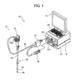
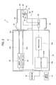
- FIG. 1 is a schematic perspective view showing an embodiment of the endoscope system of the invention and FIG. 2 conceptually shows the configuration of the endoscope system shown in FIG. 1 .
- the illustrated endoscope system 10 includes an endoscope 12, a processing device 14 for processing an image captured by the endoscope 12 and a light source device 16 for supplying white light and excitation light for use in the observation and imaging using the endoscope 12.
- the processing device 14 is connected to a monitor 18 for displaying an image captured by the endoscope and an input device 20 for inputting various instructions.
- the processing device 14 may further be connected to a printer (recording unit) for outputting an image captured by the endoscope as a hard copy.
- the endoscope system 10 of the invention is a system capable of so-called normal light observation using white light as observation light and so-called autofluorescence observation (hereinafter referred to as "fluorescence observation") in which autofluorescence from a living tissue in an observation site exposed to excitation light is measured photometrically to form an image.
- the endoscope 12 is a so-called electronic endoscope which photoelectrically captures a biological image using an imaging device such as a CCD sensor 48.
- the endoscope 12 includes an insertion section 26, an operating section 28, a universal cord 30, a connector 32 and a video connector 36.
- the endoscope 12 is used with the video connector 36 and the connector 32 connected to a connecting portion 14c of the processing device 14 and a connecting portion 16a of the light source device 16, respectively.
- the connector 32 is connected to a suction means and an air supply means for the suction from and the air supply to the observation site, and a water supply means for the water injection on the observation site.
- the insertion section 26 of the endoscope 12 includes a long flexible portion 38 on the proximal side, a distal scope portion (endoscope distal portion) 42 provided with the CCD sensor 48 and the like, and a bending portion (angle portion) 40 located between the flexible portion 38 and the scope portion 42.
- the operating section 28 of the endoscope 12 includes manipulation knobs 28a for bending the bending portion 40 and an imaging button for capturing still images.
- the scope portion 42 is provided with an imaging lens 46, the CCD sensor 48, a high-sensitivity CCD sensor 50, an excitation light cut filter 52, a half mirror 54, an illumination lens 56 and an optical fiber 58.
- the scope portion 42 also includes a cover glass (not shown) for protecting the lenses and the like.
- the endoscope 12 is also provided with a forceps channel and a forceps port for inserting various treatment tools such as a forceps, and air supply/water supply channels and air supply/water supply ports for use in suction, air supply and water supply.
- the forceps channel extends through the bending portion 40 and the flexible portion 38 to communicate with a forceps insertion port provided in the operating section 28.
- the air supply/water supply channels extend through the bending portion 40, the flexible portion 38, the operating section 28 and the universal cord 30 to communicate with connecting portions with the suction means, the air supply means and the water supply means in the connector 32.
- the optical fiber 58 extends through the bending portion 40, the flexible portion 38, the operating section 28 and the universal cord 30 and terminated by the connector 32 which is connected to the light source device 16.
- the light enters the illumination lens 56 from the distal end of the optical fiber 58 and passes through the illumination lens 56 to be irradiated on an observation site.
- Fluorescence Autofluorescence (hereinafter referred to as "fluorescence") from a living tissue in the observation site exposed to excitation light and reflected light on the living body exposed to excitation light are imaged by the high-sensitivity CCD sensor 50.
- the CCD sensor 48 is a common color CCD sensor which measures R (red) light, G (green) light and B (blue) light photometrically to form (capture) color images and is used in a common endoscope or digital camera. Therefore, the CCD sensor 48 outputs signals of an R image, a G image and a B image.
- the high-sensitivity CCD sensor 50 (hereinafter referred to as "high-sensitivity sensor 50") is the one which is used to measure R (red) light, G (green) light and B (blue) light photometrically and which can also detect weak incident light with a small quantity of light to output signals. Therefore, the high-sensitivity sensor 50 outputs signals of an R image, a G image and a B image.
- the scope portion 42 including the CCD sensor 48 and high-sensitivity sensor 50 as described above will be described later in detail.
- the imaging device is not limited to the CCD sensor 48 and various known imaging devices such as a CMOS image sensor may be used.
- the high-sensitivity sensor is not limited to the high-sensitivity CCD sensor and various known imaging devices such as a CMOS image sensor may be used as long as they are highly sensitive.
- Output signals from the CCD sensor 48 and the high-sensitivity sensor 50 are sent on signal lines from the scope portion 42 to the video connector 36 through the bending portion 40, the flexible portion 38, the operating section 28, the universal cord 30 and the connector 32.
- an AFE (Analog Front End) board 64 is disposed in the video connector 36.
- the AFE board 64 includes, for example, a correlated double sampling circuit, an amplifier (automatic gain control circuit) and an A/D converter.
- the output signals from the CCD sensor 48 and the high-sensitivity sensor 50 are subjected to noise removal by correlated double sampling and amplification in the amplifier.
- the amplified signals are further converted in the A/D converter from analog form to digital form to obtain digital image signals.
- the digital image signals are then outputted to the processing device 14 (more specifically to a DSP 72 to be described later).
- these processing steps may be performed in the connector 32 or the processing device 14 instead of the video connector 36.
- the connector 32 of the endoscope 12 in the endoscope system 10 is connected to the connecting portion 16a of the light source device 16.
- the light source device 16 supplies to the endoscope 12 white light for the normal light observation in the living body and excitation light for emitting fluorescence from the living tissue. As described above, the white light and excitation light supplied from the light source device 16 toward the endoscope 12 enters the optical fiber 58 through the connector 32 and propagates therethrough to be irradiated on the observation site through the scope portion 42 at the distal end of the insertion section 26.
- the light source device 16 of the endoscope system 10 includes a white light source 60 for emitting white light for use in the normal light observation, an excitation light source 62 for emitting excitation light for use in the fluorescence observation, and optical fibers 60a and 62a.
- the white light source 60 emits white light which is observation light for use in the so-called normal light observation in the endoscope.
- the normal light observation using white light as observation light can be performed by capturing an image only using the white light source 60 as the light source and the CCD sensor 48 (color CCD sensor) as the imaging means.
- the white light source 60 is not particularly limited and various light sources capable of emitting white light and used in endoscope systems, as exemplified by a xenon lamp and a natural light LED may be employed.
- a light source (light source device) using given phosphors which is illustrated in commonly assigned JP 2009-56248 A is also advantageously used for the white light source 60.
- Light in a first wavelength range emitted from the light source excites the phosphors to generate light in a second wavelength range and the light in the first wavelength range is combined with the light in the second wavelength range to generate white illumination light.
- the excitation light source 62 is a light source emitting excitation light which excites living tissues of the body such as porphyrin, NADH (reduced nicotinamide adenine dinucleotide), NADPH (reduced nicotinamide adenine dinucleotide phosphate) and FAD (flavin adenine dinucleotide) to emit (auto)fluorescence.
- excitation light source 62 is a light source emitting excitation light which excites living tissues of the body such as porphyrin, NADH (reduced nicotinamide adenine dinucleotide), NADPH (reduced nicotinamide adenine dinucleotide phosphate) and FAD (flavin adenine dinucleotide) to emit (auto)fluorescence.
- the excitation light is not particularly limited and light at any wavelength capable of exciting a living tissue to cause fluorescence therein can be all used.
- light at a wavelength of 370 to 470 nm is advantageously used as the excitation light from the viewpoint that the opposite properties of R fluorescence and G fluorescence from the living tissue in terms of the emission intensity which will be described later can be advantageously exhibited.
- Light at a wavelength of 400 to 450 nm can be more advantageously used because the opposite properties are exhibited and the biological safety can be more reliably ensured.
- excitation light source 62 Various light sources capable of emitting, at a sufficient intensity, excitation light causing fluorescence in living tissues can be all used for the excitation light source 62.
- various laser light sources such as a laser diode (LD) having a peak within the foregoing wavelength range are preferably used for the excitation light source 62.
- a light source such as the one described in JP 2006-43289 A which uses a white light source such as a xenon lamp and a filter passing light in a predetermined wavelength range corresponding to the excitation light can also be used for the excitation light source 62.
- the white light emitted from the white light source 60 (observation light used in the normal light observation) is propagated through the optical fiber 60a, is supplied through the connecting portion 16a to the connector 32 of the endoscope 12 and then supplied to the optical fiber 58 from the connector 32.
- the excitation light emitted from the excitation light source 62 is propagated through the optical fiber 62a, is likewise supplied through the connection portion 16a to the connector 32 of the endoscope 12 and then supplied to the optical fiber 58 from the connector 32.
- the white light and excitation light having been supplied to the optical fiber 58 are propagated through the optical fiber 58, exit from the distal end of the optical fiber 58 on the side of the scope portion 42 and pass through the illumination lens 56 to be irradiated on the observation site in the living body.
- Reflected light from the observation site of the body irradiated with the white light and fluorescence emitted from the living tissue in the observation site irradiated with the excitation light are captured and imaged via the imaging lens 46 and the half mirror 54 by the CCD sensor 48 and the high-sensitivity sensor 50, respectively.
- the half mirror 54 is disposed on the optical axis of the imaging lens 46 in the scope portion 42.
- Light which passed through the half mirror 54 is incident on the CCD sensor 48 to form an image whereas light which was reflected on the half mirror 54 is incident on the excitation light cut filter 52, through which part of light passes to be incident on the high-sensitivity sensor 50 to form an image therein.
- B elements of the high-sensitivity sensor 50 receive the excitation light reflected on the observation site of the living body to image the structure thereof.
- R and G elements of the high-sensitivity sensor 50 receive autofluorescence light.
- the excitation light cut filter is configured to block light in the wavelength band of the excitation light at predetermined positions corresponding to the R and G elements.
- FIG. 3 is a conceptual diagram showing the configuration of the excitation light cut filter 52 and the high-sensitivity sensor 50.
- the excitation light cut filter 52 is a filter which blocks light in the wavelength band of the excitation light at the positions corresponding to the R and G elements of the high-sensitivity sensor 50.
- part of the light having passed through the imaging lens 46 is incident on the excitation light cut filter 52, through which light at wavelengths outside the wavelength band of the excitation light passes to be incident on the R and G elements of the high-sensitivity sensor 50.
- the light to be received by the B elements of the high-sensitivity sensor 50 all passes through the excitation light cut filter 52 irrespective of the wavelength.
- the high-sensitivity sensor 50 detects R light from the autofluorescence in the R elements, G light from the autofluorescence in the G elements and B light as the reflected excitation light in the B elements.
- the autofluorescence images are generated from the R fluorescence, the G fluorescence and the B reflected light detected by the high-sensitivity sensor 50.
- the autofluorescence generated in the living tissue exposed to the excitation light has a low intensity or a small amount of light emission. Therefore, the entrance of the reflected excitation light into the R and G elements of the high-sensitivity sensor 50 for detecting the fluorescence may cause noise to hinder the precise detection of the R and G light from the autofluorescence.
- the high-sensitivity sensor 50 can detect weak R and G light from the autofluorescence with high precision by disposing the excitation light cut filter 52 for blocking light in the wavelength band of the excitation light at the positions corresponding to the R and G elements of the high-sensitivity sensor 50.
- the high-sensitivity sensor 50 detects the excitation light reflected on the observation site of the living body at the B elements.
- the B elements which do not detect the autofluorescence light detect the excitation light reflected on the observation site of the living body to image the structure of the observation site of the living body.
- the structure of the observation site which is not obtainable from the detection of the R light and G light from the autofluorescence can be thus obtained as a monochrome image (B intensity image).
- the configuration in which the B elements do not detect the autofluorescence light but the excitation light reflected on the observation site of the living body enables autofluorescence images and reflected light images to be obtained with one sensor and it is therefore not necessary to provide a sensor for imaging the structure of an observation site separately from a sensor for capturing autofluorescence images when the fluorescence observation is performed.
- Various filters which block the excitation light and pass light on the longer wavelength side than the wavelength band of the excitation light (wavelength band including at least an R light region) at the positions corresponding to the R and G elements of the high-sensitivity sensor 50 can be used for the excitation light cut filter 52.
- An exemplary filter that may be used includes one which blocks light at wavelengths equal to or shorter than the maximum wavelength of the excitation light and passes light on the longer wavelength side than the maximum wavelength of the excitation light. More specifically, when the excitation light source 62 is a laser light source having a central wavelength of 400 nm, the excitation light cut filter 52 which blocks light at wavelengths equal to or shorter than 420 nm and preferably equal to or shorter than 410 nm, and passes light at wavelengths on the longer wavelength side may be used.
- excitation light cut filters including the one described therein can be used.
- the white light (observation light) is continuously emitted only from the white light source 60 of the light source device 16 to image only in the CCD sensor 48 thereby capturing normal light observation images as in the normal light observation using a common endoscope system.
- the light source device 16 continuously emits excitation light only from the excitation light source 62 to image in the high-sensitivity sensor 50 thereby capturing autofluorescence images.
- the invention uses the half mirror 54 to change the optical path to supply light to one of the CCD sensor 48 and the high-sensitivity sensor 50 but the invention is not limited to this configuration.
- a total reflection mirror may be inserted into or retracted from the optical path so that the subsequent optical path is directed to the CCD sensor 48 or the high-sensitivity sensor 50.
- the endoscope used in the endoscope system 10 of the invention is of a so-called one-lens two-sensor configuration in which two imaging devices for use in the normal light observation and fluorescence observation are provided for one imaging lens 46, and the CCD sensor 48 and the high-sensitivity sensor 50 are selectively used by changing the optical path.
- the invention is not limited to this.
- a two-lens two-sensor configuration may be used in which an imaging device for use in the normal light observation and an imaging device for use in the fluorescence observation each have the corresponding imaging lens as long as the same observation site can be imaged by switching between the normal light observation image mode and the fluorescence image mode.
- output signals from the CCD sensor 48 and the high-sensitivity sensor 50 are sent to the video connector 36, subjected to processing such as A/D conversion in the AFE 64 and supplied to the processing device 14 (more specifically a processor 14a thereof) as a digital image (digital image signals (image data/image information)).
- the processing device 14 subjects the normal light observation images and autofluorescence images (hereinafter also collectively referred to simply as "images" when it is not necessary to distinguish them from each other) supplied (outputted) from the endoscope 12 to predetermined processing so that the monitor 18 displays them as the images captured by the endoscope 12 and also controls the endoscope system 10.
- images normal light observation images and autofluorescence images
- the processing device 14 includes the image processor 14a and a controller 14b for controlling the whole of the endoscope system 10 including the processing device 14.
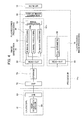
- FIG. 4 is a conceptual block diagram showing the image processor 14a of the processing device 14.
- the processor 14a includes the DSP 72, a storage section 74, an image generating section 76, a fluorescence image processing section 78 and a display image generating section 80.
- images from the endoscope 12 are supplied to the DSP 72.
- the DSP 72 is a known type of DSP (Digital Signal Processor), where the supplied autofluorescence images are subjected to predetermined processing steps such as gamma correction and color correction. The processed images are then stored in a predetermined region of the storage section (memory) 74.
- DSP Digital Signal Processor
- the image generating section 76 or the fluorescence image processing section 78 Upon the storage of the normal light images or autofluorescence images in the storage section 74, the image generating section 76 or the fluorescence image processing section 78 reads out images and performs predetermined processing on the read-out images.
- the fluorescence image processing section 78 includes a read-out portion 84 and an R F /G F arithmetic portion 86.
- the fluorescence image processing section 78 only functions when the fluorescence observation is performed.
- the read-out portion 84 of the fluorescence image processing section 78 which is under the control of the controller 14b reads out the autofluorescence images and supplies them to the R F /G F arithmetic portion 86.
- the high-sensitivity sensor 50 photometrically measures R light and G light as autofluorescence emitted from the living tissue exposed to the excitation light and B light as light reflected from the living body when the excitation light enters the observation site, thereby capturing the autofluorescence images. Therefore, the read-out portion 84 reads out the R fluorescence image R F and the G fluorescence image G F and supplies them to the R F /G F arithmetic portion 86.
- the R F /G F arithmetic portion 86 uses the supplied fluorescence images R F and G F to calculate the ratio R F /G F between the fluorescence image R F and the fluorescence image G F and supply the calculated ratio to a fluorescence processing portion 92 of the image generating section 76 to be described below.
- the image generating section 76 includes a read-out portion 90, the fluorescence processing portion 92 and an image correcting portion 94.
- the read-out portion 90 of the image generating section 76 reads out images stored in the storage section 74.
- the read-out portion 90 reads out an R normal image R N , a G normal image G N and a B normal image B N .
- the fluorescence processing portion 92 only functions when the fluorescence imaging is performed. Therefore, when the normal light observation is performed, the normal images R N , G N and B N read out by the read-out portion 84 pass through the fluorescence processing portion 92 to be directly supplied to the image correcting portion 94 as an R image R D , a G image G D and a B image B D without being processed in the fluorescence processing portion 92.
- the image correcting portion 94 subjects the R, G and B images to processing with a 3x3 matrix, gradation conversion, processing with a three-dimensional LUT or other color conversion processing; color enhancement for giving a color difference between a blood vessel and a mucous membrane on the screen by enhancing in a direction in which the color difference between the blood vessel and the mucous membrane is to be more accentuated than the average colors of the image so that the blood vessel can be more easily seen; image structure enhancement such as sharpening and edge enhancement, and other image correction steps and supplies the corrected image to the display image generating section 80 as the images for display.
- the R fluorescence image R F , the G fluorescence image G F and the B fluorescence image B F read out by the read-out portion 90 are supplied to the image correcting portion 94 as an R image R D , a G image G D and a B image B D after being subjected to predetermined processing in the fluorescence processing portion 92.
- the image correcting portion 94 performs the same image correction as above and sends the corrected images to the display image generating section 80 as the images for display.
- the fluorescence processing portion 92 includes an R image processing portion 92r, a G image processing portion 92g and a B image processing portion 92b.
- the image processing portions process the autofluorescence images (respective pixels thereof) using the ratio R F /G F calculated by the R F /G F arithmetic portion 86 (R F/ G F for the respective pixels of the autofluorescence images). More specifically, the R image processing portion 92r processes the fluorescence image R F to generate the R image R D , the G image processing portion 92g processes the fluorescence image G F to generate the G image G D and the B image processing portion 92b processes the fluorescence image B F to generate the B image B D .
- the image processing portions of the fluorescence processing portion 92 process the autofluorescence images with R F /G F by the following formulas (1) to (3) to generate the images R D , G D and B D , respectively.
- R D R F ⁇ 1 + ⁇ ⁇ R F / G F
- G D G F ⁇ 1 + ⁇ ⁇ R F / G F
- B D B F
- ⁇ is a preferably used coefficient which is appropriately set so that R F /G F in the lesion area may approach 1 and more preferably R F /G F in the normal area may approach 0.
- FIG. 5 shows spectra of autofluorescence from a living tissue when a living body (human colonic mucosa) is irradiated with light at a central wavelength of 380 nm emitted from the laser light source as excitation light.
- the horizontal axis shows the autofluorescence wavelength and the vertical axis shows the autofluorescence intensity
- the solid line shows the autofluorescence from the lesion area and the broken line shows the autofluorescence from the normal area.
- the R fluorescence image R F is mainly formed by R fluorescence due to porphyrin and the G fluorescence image G F is mainly formed by G fluorescence due to NADH and NADPH.
- the fluorescence making up the fluorescence image R F As is seen from, for example, the fluorescence property at around 630 nm, the normal area does not show very strong fluorescence whereas the lesion area shows very strong fluorescence.
- the G fluorescence making up the fluorescence image G F As is seen from, for example, the fluorescence property at around 470 nm to 530 nm, the normal area shows strong fluorescence whereas the lesion area does not show very strong fluorescence.
- the fluorescence image R F and the fluorescence image G F obtained by exposure of the living tissue to B light as excitation light have opposite properties in terms of the intensity in the normal area and the lesion area.
- the lesion area can be enhanced by making use of the opposite properties of the fluorescence image R F and the fluorescence image G F in the lesion area and the normal area.
- the lesion area has a higher intensity in the fluorescence image R F and a lower intensity in the fluorescence image G F and the ratio R F /G F is therefore increased.
- the normal area has a lower intensity in the fluorescence image R F and a higher intensity in the fluorescence image G F and the ratio R F /G F is therefore decreased. Accordingly, this relation is used to process the fluorescence image R F as the autofluorescence image by, for example, multiplication or addition of R F/ G F to enhance the lesion area of the autofluorescence image, thus enabling the lesion area of the obtained image to be enhanced with red.
- the fluorescence image G F as the autofluorescence image is processed by, for example, division or subtraction of R F /G F to suppress the lesion area in the fluorescence image G F as the autofluorescence image, thus enabling the lesion area of the obtained image to be enhanced with the fluorescence image R F , that is, with red.
- the fluorescence image B F is an image acquired by detecting the reflected excitation light and includes the biological structure and therefore the fluorescence image B F is not processed with R F /G F but is directly used as the image B D as shown in formula (3), whereby the biological structure can be suitably displayed on the image.
- ⁇ x R F /G F is added to 1 and multiplied by the fluorescence image R F to calculate the image R D .
- ⁇ x R F /G F is subtracted from 1 and multiplied by the fluorescence image G F to calculate the image G D .
- R F /G F is or is close to 0 in the normal area and the normal images including R, G and B images are multiplied by 1 or a value close to 1. Therefore, the normal area has no large image changes between the autofluorescence images and the images R D , G D and B D , respectively.
- the fluorescence image R F is multiplied by 2 or a value close to 2 in the lesion area and the image R D is enhanced twice as large as that of the fluorescence image R F .
- the fluorescence image G F is multiplied by 0 or a value closer to 0 and the image G D has a value close to 0.
- the lesion area of the obtained image is enhanced with red with respect to the normal area.
- the invention can enhance the fluorescence image R F having an increased autofluorescence intensity in the lesion area and suppress the fluorescence image G F showing no very high fluorescence in the lesion area, thereby highlighting the lesion area with the color of the fluorescence image R F .
- fluorescence images with enhanced lesion area can be used to correctly identify the lesion area and the normal area.
- the coefficient ⁇ is preferably used in the processing of the normal images with R F /G F in the fluorescence processing portion 92 and is appropriately set so that R F /G F may approach 1 in the lesion area.
- the coefficient ⁇ is more preferably a coefficient appropriately set so that R F /G F in the lesion area may approach 1 and R F /G F in the normal area may approach 0.
- the coefficient ⁇ as described above may be appropriately set according to the device characteristics of the endoscope 12 and the light source device 16 such as the spectral sensitivity characteristics of the high-sensitivity sensor 50 (band characteristics of the filter and the spectral sensitivity of the device), the wavelength of the excitation light emitted from the light source device 16 (spectral characteristics), and the spectral characteristics of the excitation light cut filter 52 (filter characteristics) so that R F /G F may approach or be 1 in the lesion area.
- the coefficient ⁇ is appropriately set according to the device characteristics so that R F /G F may approach 1 in the lesion area and approach or be 0 in the normal area.
- the coefficient ⁇ is preferably used and is not essential.
- R F /G F may take a value close to 1 in the lesion area and optionally a value close to 0 in the normal area without using the coefficient ⁇ .
- the processing of the fluorescence images R F and G F includes the addition or subtraction of R F /G F to or from 1 but the invention is not limited thereto.
- R F /G F may be directly multiplied by the fluorescence images to calculate the images R D and G D .
- R F /G F may be directly added to or subtracted from the fluorescence images to calculate the images R D and G D .
- the R and G images are processed with a correction factor including R F /G F but the B image is not processed with a correction factor including R F /G F , thus calculating the images R D , G D and B D .
- the invention is not limited to this method.
- the images R D , G D and B D may be calculated by performing the operation represented by the formula (1) for the R image and performing no processing on the G and B images.
- the normal images R N , G N and B N read out by the read-out portion 90 are not processed in the fluorescence processing portion 92 and are supplied to the image correcting portion 94 as the images R D , G D and B D .
- the autofluorescence images R F , G F and B F read out by the read-out portion 90 are processed with R F /G F in the fluorescence processing portion 92 and supplied to the image correcting portion 94 as the images R D , G D and B D .
- the images R D , G D and B D are subjected to predetermined processing such as color conversion or image structure enhancement in the image correcting portion 94 before being supplied to the display image generating section 80 as images for display (normal light observation images/fluorescence images).
- the display image generating section 80 subjects the normal light observation images and fluorescence images supplied from the image generating section 76 to color space conversion, scaling and other necessary processing steps, or image allocation, incorporation of character information such as the name of a subject and other necessary processing steps to generate a display image having the composite image incorporated therein and this image is displayed on the monitor 18.
- the excitation light source 62 of the light source device 16 is turned on.
- the high-sensitivity sensor 50 of the endoscope 12 simultaneously starts imaging.
- the excitation light emitted from the excitation light source 62 is propagated through the optical fiber 62a and is supplied through the connection portion 16a to the connector 32 of the endoscope 12.
- the excitation light supplied to the connector 32 of the endoscope 12 is propagated through the optical fiber 58 to the scope portion 42, where the excitation light exit from the distal end of the optical fiber 58 to be irradiated on the observation site of the living body.
- the high-sensitivity sensor 50 captures the excitation light irradiated on the observation site to output autofluorescence images composed of the R fluorescence and G fluorescence from the living tissue of the observation site and the reflected B light of the excitation light.
- Output signals from the high-sensitivity sensor 50 are supplied to the AFE board 64.
- the AFE board 64 subjects the output signals from the high-sensitivity sensor 50 to noise removal by correlated double sampling, amplification and A/D conversion to obtain digital image signals, which are then supplied to the DSP 72 of the processing device 14 (processor 14a).
- the DSP 72 subjects the supplied images (image signals) to predetermined processing such as gamma correction and color correction and the processed images are stored in a predetermined portion of the storage unit 74.
- the read-out portion 84 of the fluorescence image processing section 78 reads out the R fluorescence image R F and the G fluorescence image G F captured by the high-sensitivity sensor 50 and supplies them to the R F/ G F arithmetic portion 86.
- the R F/ G F arithmetic portion 86 calculates R F /G F and supplies it to the fluorescence processing portion 92 (R image processing portion 92r, G image processing portion 92g and B image processing portion 92b).
- the read-out portion 90 of the image generating section 76 reads out the R fluorescence image R F , G fluorescence image G F and B fluorescence image B F and supplies them to the fluorescence processing portion 92.
- the R image processing portion 92r, the G image processing portion 92g and the B image processing portion 92b process the fluorescence image R F , fluorescence image G F and fluorescence image B F by the formulas (1), (2) and (3) using R F /G F to obtain the images R D , G D and B D , respectively.
- the images R D , G D and B D obtained in the fluorescence processing portion 92 are then subjected to predetermined image correction steps such as color conversion and image structure processing in the image correcting portion 94.
- a display image is generated in the display image generating section 80 and is displayed on the monitor 18 as a fluorescence image.
- the display image is an image in which the lesion area captured in the fluorescence observation mode is enhanced with red and therefore the normal area and lesion area are easily identified.
- the illustrated endoscope system 10 is configured so that the B elements of the high-sensitivity sensor 50 detect the excitation light reflected on the observation site of the living body to capture the biological structure as a monochrome image in the fluorescence observation mode.
- the B elements of the high-sensitivity sensor 50 may detect nothing in the fluorescence observation mode.
- the R or G image may be allocated to the B image.
- the illustrated endoscope system 10 is also configured so that the images obtained by the operations of the fluorescence images R F , G F and B F are allocated to the images R D , G D and B D , respectively, as shown in the formulas (1) to (3).
- this is not the sole case of the invention and the images obtained by the operations of the fluorescence images may be allocated by any combination.
- , the image obtained by the operation of the fluorescence image G F be allocated to the image B D as represented by the formula: B D G F ⁇
- and the image obtained by the operation of the fluorescence image B F be allocated to the image R D as represented by the formula: R D B F .
Landscapes
- Life Sciences & Earth Sciences (AREA)
- Health & Medical Sciences (AREA)
- Surgery (AREA)
- Engineering & Computer Science (AREA)
- Biophysics (AREA)
- Medical Informatics (AREA)
- Nuclear Medicine, Radiotherapy & Molecular Imaging (AREA)
- Optics & Photonics (AREA)
- Pathology (AREA)
- Radiology & Medical Imaging (AREA)
- Veterinary Medicine (AREA)
- Biomedical Technology (AREA)
- Heart & Thoracic Surgery (AREA)
- Physics & Mathematics (AREA)
- Molecular Biology (AREA)
- Animal Behavior & Ethology (AREA)
- General Health & Medical Sciences (AREA)
- Public Health (AREA)
- Signal Processing (AREA)
- Endoscopes (AREA)
- Instruments For Viewing The Inside Of Hollow Bodies (AREA)
Applications Claiming Priority (1)
| Application Number | Priority Date | Filing Date | Title |
|---|---|---|---|
| JP2011008571A JP5485190B2 (ja) | 2011-01-19 | 2011-01-19 | 内視鏡装置 |
Publications (1)
| Publication Number | Publication Date |
|---|---|
| EP2478826A1 true EP2478826A1 (fr) | 2012-07-25 |
Family
ID=45478142
Family Applications (1)
| Application Number | Title | Priority Date | Filing Date |
|---|---|---|---|
| EP11196079A Withdrawn EP2478826A1 (fr) | 2011-01-19 | 2011-12-29 | Système d'endoscope |
Country Status (3)
| Country | Link |
|---|---|
| US (1) | US20120184813A1 (fr) |
| EP (1) | EP2478826A1 (fr) |
| JP (1) | JP5485190B2 (fr) |
Families Citing this family (16)
| Publication number | Priority date | Publication date | Assignee | Title |
|---|---|---|---|---|
| JP5628062B2 (ja) * | 2011-02-01 | 2014-11-19 | 富士フイルム株式会社 | 電子内視鏡システム |
| CN103561626B (zh) * | 2011-06-03 | 2015-12-02 | 奥林巴斯株式会社 | 荧光观察装置和荧光观察方法 |
| CN104066368B (zh) | 2011-09-22 | 2017-02-22 | 乔治华盛顿大学 | 用于使经消融组织可视化的系统和方法 |
| ES2727868T3 (es) | 2011-09-22 | 2019-10-21 | Univ George Washington | Sistemas para visualizar el tejido ablacionado |
| EP2979611A4 (fr) * | 2013-03-29 | 2016-12-14 | Olympus Corp | Dispositif d'observation de fluorescence |
| JP6737705B2 (ja) | 2013-11-14 | 2020-08-12 | ザ・ジョージ・ワシントン・ユニバーシティThe George Washingtonuniversity | 損傷部位の深さを決定するシステムの動作方法及び心臓組織の画像を生成するシステム |
| US20150141847A1 (en) | 2013-11-20 | 2015-05-21 | The George Washington University | Systems and methods for hyperspectral analysis of cardiac tissue |
| US10451553B2 (en) * | 2014-04-03 | 2019-10-22 | Hitachi High-Technologies Corporation | Fluorescence spectrometer |
| JP6771731B2 (ja) | 2014-11-03 | 2020-10-21 | 460メディカル・インコーポレイテッド460Medical, Inc. | 接触性評価システム及び方法 |
| EP3215002B1 (fr) | 2014-11-03 | 2024-03-20 | The George Washington University | Systèmes d'évaluation de lésion |
| US10292592B2 (en) * | 2014-11-13 | 2019-05-21 | The Board Of Trustees Of The Leland Stanford Junior University | Method and apparatus for optical recording of biological parameters in freely moving animals |
| US10779904B2 (en) | 2015-07-19 | 2020-09-22 | 460Medical, Inc. | Systems and methods for lesion formation and assessment |
| WO2018142658A1 (fr) * | 2017-02-01 | 2018-08-09 | オリンパス株式会社 | Dispositif de traitement d'images, procédé de fonctionnement pour dispositif de traitement d'images et programme de fonctionnement pour dispositif de traitement d'images |
| JP7159441B2 (ja) * | 2019-03-05 | 2022-10-24 | オリンパス株式会社 | 内視鏡装置および内視鏡装置の作動方法 |
| US12076081B2 (en) | 2020-01-08 | 2024-09-03 | 460Medical, Inc. | Systems and methods for optical interrogation of ablation lesions |
| WO2021243061A1 (fr) | 2020-05-27 | 2021-12-02 | The George Washington University | Visualisation de lésions par une approche à deux longueurs d'onde |
Citations (5)
| Publication number | Priority date | Publication date | Assignee | Title |
|---|---|---|---|---|
| US5647368A (en) * | 1996-02-28 | 1997-07-15 | Xillix Technologies Corp. | Imaging system for detecting diseased tissue using native fluorsecence in the gastrointestinal and respiratory tract |
| US20020062061A1 (en) * | 1997-09-24 | 2002-05-23 | Olympus Optical Co., Ltd. | Fluorescent imaging device |
| JP2006043289A (ja) | 2004-08-06 | 2006-02-16 | Olympus Corp | 内視鏡装置 |
| JP3810337B2 (ja) | 1991-05-08 | 2006-08-16 | ジリックス・テクノロジイズ・コーポレーション | 撮像装置 |
| JP2009056248A (ja) | 2007-09-03 | 2009-03-19 | Fujifilm Corp | 光源装置、および光源装置の駆動制御方法、並びに内視鏡 |
Family Cites Families (21)
| Publication number | Priority date | Publication date | Assignee | Title |
|---|---|---|---|---|
| JPS58194488A (ja) * | 1982-05-07 | 1983-11-12 | Nippon Kogaku Kk <Nikon> | 色バランス調整装置 |
| US5092331A (en) * | 1989-01-30 | 1992-03-03 | Olympus Optical Co., Ltd. | Fluorescence endoscopy and endoscopic device therefor |
| US5769792A (en) * | 1991-07-03 | 1998-06-23 | Xillix Technologies Corp. | Endoscopic imaging system for diseased tissue |
| US6571119B2 (en) * | 1996-03-06 | 2003-05-27 | Fuji Photo Film Co., Ltd. | Fluorescence detecting apparatus |
| JP3796635B2 (ja) * | 1996-03-06 | 2006-07-12 | 富士写真フイルム株式会社 | 蛍光検出装置 |
| US7179222B2 (en) * | 1996-11-20 | 2007-02-20 | Olympus Corporation | Fluorescent endoscope system enabling simultaneous achievement of normal light observation based on reflected light and fluorescence observation based on light with wavelengths in infrared spectrum |
| JP3654325B2 (ja) * | 1997-02-13 | 2005-06-02 | 富士写真フイルム株式会社 | 蛍光検出装置 |
| JP3923595B2 (ja) * | 1997-05-13 | 2007-06-06 | オリンパス株式会社 | 蛍光観察装置 |
| DE69938493T2 (de) * | 1998-01-26 | 2009-05-20 | Massachusetts Institute Of Technology, Cambridge | Endoskop zur erfassung von fluoreszenzbilder |
| US6364829B1 (en) * | 1999-01-26 | 2002-04-02 | Newton Laboratories, Inc. | Autofluorescence imaging system for endoscopy |
| JP2001104237A (ja) * | 1999-10-05 | 2001-04-17 | Fuji Photo Film Co Ltd | 蛍光判定方法および装置 |
| EP1097670B1 (fr) * | 1999-11-02 | 2010-10-27 | FUJIFILM Corporation | Appareil de visualisation de fluorescence |
| JP3983947B2 (ja) * | 1999-11-16 | 2007-09-26 | 富士フイルム株式会社 | 蛍光画像表示方法および装置 |
| US6468204B2 (en) * | 2000-05-25 | 2002-10-22 | Fuji Photo Film Co., Ltd. | Fluorescent endoscope apparatus |
| DE60228165D1 (de) * | 2001-05-16 | 2008-09-25 | Olympus Corp | Endoskop mit Bildverarbeitungseinrichtung |
| US7697975B2 (en) * | 2003-06-03 | 2010-04-13 | British Colombia Cancer Agency | Methods and apparatus for fluorescence imaging using multiple excitation-emission pairs and simultaneous multi-channel image detection |
| US20050059894A1 (en) * | 2003-09-16 | 2005-03-17 | Haishan Zeng | Automated endoscopy device, diagnostic method, and uses |
| US20060173358A1 (en) * | 2005-01-11 | 2006-08-03 | Olympus Corporation | Fluorescence observation endoscope apparatus and fluorescence observation method |
| JP4681981B2 (ja) * | 2005-08-18 | 2011-05-11 | Hoya株式会社 | 電子内視鏡装置 |
| WO2008028298A1 (fr) * | 2006-09-06 | 2008-03-13 | University Health Network | Quantification de fluorescence et acquisition d'image dans un support extrêmement trouble |
| JP5295587B2 (ja) * | 2008-02-27 | 2013-09-18 | オリンパスメディカルシステムズ株式会社 | 蛍光内視鏡装置及び蛍光内視鏡装置の作動方法 |
-
2011
- 2011-01-19 JP JP2011008571A patent/JP5485190B2/ja not_active Expired - Fee Related
- 2011-12-29 US US13/340,471 patent/US20120184813A1/en not_active Abandoned
- 2011-12-29 EP EP11196079A patent/EP2478826A1/fr not_active Withdrawn
Patent Citations (5)
| Publication number | Priority date | Publication date | Assignee | Title |
|---|---|---|---|---|
| JP3810337B2 (ja) | 1991-05-08 | 2006-08-16 | ジリックス・テクノロジイズ・コーポレーション | 撮像装置 |
| US5647368A (en) * | 1996-02-28 | 1997-07-15 | Xillix Technologies Corp. | Imaging system for detecting diseased tissue using native fluorsecence in the gastrointestinal and respiratory tract |
| US20020062061A1 (en) * | 1997-09-24 | 2002-05-23 | Olympus Optical Co., Ltd. | Fluorescent imaging device |
| JP2006043289A (ja) | 2004-08-06 | 2006-02-16 | Olympus Corp | 内視鏡装置 |
| JP2009056248A (ja) | 2007-09-03 | 2009-03-19 | Fujifilm Corp | 光源装置、および光源装置の駆動制御方法、並びに内視鏡 |
Also Published As
| Publication number | Publication date |
|---|---|
| US20120184813A1 (en) | 2012-07-19 |
| JP2012147927A (ja) | 2012-08-09 |
| JP5485190B2 (ja) | 2014-05-07 |
Similar Documents
| Publication | Publication Date | Title |
|---|---|---|
| EP2478826A1 (fr) | Système d'endoscope | |
| EP2478827A1 (fr) | Système d'endoscope | |
| JP5815426B2 (ja) | 内視鏡システム、内視鏡システムのプロセッサ装置、及び画像処理方法 | |
| JP5081720B2 (ja) | 蛍光内視鏡装置および励起光ユニット | |
| JP5303012B2 (ja) | 内視鏡システム、内視鏡システムのプロセッサ装置及び内視鏡システムの作動方法 | |
| US8915844B2 (en) | Endoscope diagnostic apparatus | |
| JP5887350B2 (ja) | 内視鏡システム及びその作動方法 | |
| US20170020377A1 (en) | Fluorescence observation endoscope system | |
| JP5914496B2 (ja) | 内視鏡システム及びプロセッサ装置並びに内視鏡システムの作動方法 | |
| JP4855728B2 (ja) | 照明装置及び観察装置 | |
| JP5623469B2 (ja) | 内視鏡システム、内視鏡システムのプロセッサ装置、及び内視鏡用制御プログラム | |
| US9629527B2 (en) | Endoscope system, processor device of endoscope system, and image processing method | |
| US20160157763A1 (en) | Fluorescence observation device, endoscopic system, processor device, and operation method | |
| EP2095758B1 (fr) | Dispositif endoscopique fluorescent et procédé pour créer une image endoscopique fluorescente | |
| EP2505121B1 (fr) | Appareil d'endoscope | |
| JP5539841B2 (ja) | 電子内視鏡システム、電子内視鏡システムのプロセッサ装置、及び電子内視鏡システムの作動方法 | |
| JP6100674B2 (ja) | 内視鏡用光源装置及び内視鏡システム | |
| JP5147538B2 (ja) | 蛍光画像取得装置および蛍光画像取得装置の作動方法 | |
| JP5780653B2 (ja) | 光源装置及び内視鏡システム | |
| JP2012081048A (ja) | 電子内視鏡システム、電子内視鏡、及び励起光照射方法 | |
| JP5525991B2 (ja) | 電子内視鏡システム、電子内視鏡システムのプロセッサ装置、及び電子内視鏡システムの作動方法 | |
| JP6325707B2 (ja) | 内視鏡用光源装置及び内視鏡システム | |
| JP2015231467A (ja) | 内視鏡用光源装置及び内視鏡システム | |
| JP2010148646A (ja) | 内視鏡、内視鏡システムおよび内視鏡駆動方法 | |
| JP2015231576A (ja) | 内視鏡システム、内視鏡システムのプロセッサ装置、及び画像処理方法 |
Legal Events
| Date | Code | Title | Description |
|---|---|---|---|
| PUAI | Public reference made under article 153(3) epc to a published international application that has entered the european phase |
Free format text: ORIGINAL CODE: 0009012 |
|
| AK | Designated contracting states |
Kind code of ref document: A1 Designated state(s): AL AT BE BG CH CY CZ DE DK EE ES FI FR GB GR HR HU IE IS IT LI LT LU LV MC MK MT NL NO PL PT RO RS SE SI SK SM TR |
|
| AX | Request for extension of the european patent |
Extension state: BA ME |
|
| 17P | Request for examination filed |
Effective date: 20130117 |
|
| STAA | Information on the status of an ep patent application or granted ep patent |
Free format text: STATUS: THE APPLICATION HAS BEEN WITHDRAWN |
|
| 18W | Application withdrawn |
Effective date: 20150710 |