EP2479082A2 - Transportwagen mit Verschlussvorrichtung - Google Patents
Transportwagen mit Verschlussvorrichtung Download PDFInfo
- Publication number
- EP2479082A2 EP2479082A2 EP12151143A EP12151143A EP2479082A2 EP 2479082 A2 EP2479082 A2 EP 2479082A2 EP 12151143 A EP12151143 A EP 12151143A EP 12151143 A EP12151143 A EP 12151143A EP 2479082 A2 EP2479082 A2 EP 2479082A2
- Authority
- EP
- European Patent Office
- Prior art keywords
- closure
- control device
- door
- closure control
- trolley
- Prior art date
- Legal status (The legal status is an assumption and is not a legal conclusion. Google has not performed a legal analysis and makes no representation as to the accuracy of the status listed.)
- Granted
Links
- 230000000717 retained effect Effects 0.000 claims description 4
- 235000013305 food Nutrition 0.000 description 6
- 235000013361 beverage Nutrition 0.000 description 4
- 230000000295 complement effect Effects 0.000 description 4
- 230000006835 compression Effects 0.000 description 2
- 238000007906 compression Methods 0.000 description 2
- 238000001816 cooling Methods 0.000 description 2
- 238000010438 heat treatment Methods 0.000 description 2
- 230000014759 maintenance of location Effects 0.000 description 2
- 238000005496 tempering Methods 0.000 description 2
- 229920005830 Polyurethane Foam Polymers 0.000 description 1
- 235000021167 banquet Nutrition 0.000 description 1
- 238000006073 displacement reaction Methods 0.000 description 1
- 230000000694 effects Effects 0.000 description 1
- 238000007373 indentation Methods 0.000 description 1
- 239000011810 insulating material Substances 0.000 description 1
- 239000000463 material Substances 0.000 description 1
- 239000007769 metal material Substances 0.000 description 1
- 238000000034 method Methods 0.000 description 1
- 230000002093 peripheral effect Effects 0.000 description 1
- 239000011496 polyurethane foam Substances 0.000 description 1
- 229910001220 stainless steel Inorganic materials 0.000 description 1
- 239000010935 stainless steel Substances 0.000 description 1
- 239000000758 substrate Substances 0.000 description 1
- 230000007704 transition Effects 0.000 description 1
- 238000003466 welding Methods 0.000 description 1
Images






Classifications
-
- B—PERFORMING OPERATIONS; TRANSPORTING
- B62—LAND VEHICLES FOR TRAVELLING OTHERWISE THAN ON RAILS
- B62B—HAND-PROPELLED VEHICLES, e.g. HAND CARTS OR PERAMBULATORS; SLEDGES
- B62B3/00—Hand carts having more than one axis carrying transport wheels; Steering devices therefor; Equipment therefor
- B62B3/002—Hand carts having more than one axis carrying transport wheels; Steering devices therefor; Equipment therefor characterised by a rectangular shape, involving sidewalls or racks
- B62B3/003—Non-transparent side walls
-
- B—PERFORMING OPERATIONS; TRANSPORTING
- B62—LAND VEHICLES FOR TRAVELLING OTHERWISE THAN ON RAILS
- B62B—HAND-PROPELLED VEHICLES, e.g. HAND CARTS OR PERAMBULATORS; SLEDGES
- B62B3/00—Hand carts having more than one axis carrying transport wheels; Steering devices therefor; Equipment therefor
- B62B3/002—Hand carts having more than one axis carrying transport wheels; Steering devices therefor; Equipment therefor characterised by a rectangular shape, involving sidewalls or racks
- B62B3/004—Details of doors or cover lids
-
- E—FIXED CONSTRUCTIONS
- E05—LOCKS; KEYS; WINDOW OR DOOR FITTINGS; SAFES
- E05B—LOCKS; ACCESSORIES THEREFOR; HANDCUFFS
- E05B17/00—Accessories in connection with locks
- E05B17/20—Means independent of the locking mechanism for preventing unauthorised opening, e.g. for securing the bolt in the fastening position
- E05B17/2007—Securing, deadlocking or "dogging" the bolt in the fastening position
- E05B17/203—Securing, deadlocking or "dogging" the bolt in the fastening position not following the movement of the bolt
- E05B17/2034—Securing, deadlocking or "dogging" the bolt in the fastening position not following the movement of the bolt moving pivotally or rotatively
-
- E—FIXED CONSTRUCTIONS
- E05—LOCKS; KEYS; WINDOW OR DOOR FITTINGS; SAFES
- E05C—BOLTS OR FASTENING DEVICES FOR WINGS, SPECIALLY FOR DOORS OR WINDOWS
- E05C19/00—Other devices specially designed for securing wings, e.g. with suction cups
- E05C19/02—Automatic catches, i.e. released by pull or pressure on the wing
- E05C19/028—Automatic catches, i.e. released by pull or pressure on the wing with sliding bolt(s)
-
- E—FIXED CONSTRUCTIONS
- E05—LOCKS; KEYS; WINDOW OR DOOR FITTINGS; SAFES
- E05B—LOCKS; ACCESSORIES THEREFOR; HANDCUFFS
- E05B1/00—Knobs or handles for wings; Knobs, handles, or press buttons for locks or latches on wings
- E05B1/003—Handles pivoted about an axis perpendicular to the wing
-
- E—FIXED CONSTRUCTIONS
- E05—LOCKS; KEYS; WINDOW OR DOOR FITTINGS; SAFES
- E05B—LOCKS; ACCESSORIES THEREFOR; HANDCUFFS
- E05B15/00—Other details of locks; Parts for engagement by bolts of fastening devices
- E05B15/0053—Other details of locks; Parts for engagement by bolts of fastening devices means providing a stable, i.e. indexed, position of lock parts
- E05B15/006—Spring-biased ball or roller entering a notch
-
- E—FIXED CONSTRUCTIONS
- E05—LOCKS; KEYS; WINDOW OR DOOR FITTINGS; SAFES
- E05B—LOCKS; ACCESSORIES THEREFOR; HANDCUFFS
- E05B53/00—Operation or control of locks by mechanical transmissions, e.g. from a distance
-
- E—FIXED CONSTRUCTIONS
- E05—LOCKS; KEYS; WINDOW OR DOOR FITTINGS; SAFES
- E05B—LOCKS; ACCESSORIES THEREFOR; HANDCUFFS
- E05B63/00—Locks or fastenings with special structural characteristics
- E05B63/22—Locks or fastenings with special structural characteristics operated by a pulling or pushing action perpendicular to the front plate, i.e. by pulling or pushing the wing itself
Definitions
- the present invention relates to a trolley comprising a body, at least one door and a closure device for retaining the door in a closed position of the door and a retaining position of the closure device.
- trolleys with closure devices that are movable only by an operation from outside the trolley from the restraint position to a release position in which the door can be opened.
- closure devices that are movable only by an operation from outside the trolley from the restraint position to a release position in which the door can be opened.
- dolly have the disadvantage that a person inadvertently trapped in the interior of the body, such as a child playing, the door can not open from the inside to escape from the interior.
- trolleys with closure devices which indeed allow the door to be opened from the interior of the carcass, but then it is not possible to lock the closure device in the restraint position, so that there is the danger that the door, in particular in a Transportation process of the trolley, unintentionally opens.
- the present invention has for its object to provide a trolley of the type mentioned, which allows both an opening of the door from an interior of the carcass and a secure locking of the door in its closed position during a transport operation of the trolley, and thereby easy and safe to use.
- a trolley with the features of the preamble of claim 1 according to the invention in that the trolley comprises a closure control device having a locking position, in which the closure control device so cooperates with the closure device, that the closure device is locked in its restraint position, and wherein the closure control device additionally comprises a safety position in which the closure control device cooperates with the closure device such that the closure device is movable from its restraint position into a release position and the door can be opened from an interior of the body.
- the invention is thus based on the concept of integrating in one and the same locking system the possibility of securely locking the door by locking the locking device in its retaining position on the one hand and the possibility of opening the door from the interior of the body on the other hand.
- the door in the safety position by exerting pressure on a the interior of the body facing the inside of the door to open.
- the transport carriage comprises at least one biasing element, which biases the closure device in its retaining position in the safety position of the closure control device.
- Such a biasing element may in particular comprise a spring element.
- Such a spring element may in particular be designed as a tension spring or as a compression spring.
- the closure control device has, in addition to the locking position and the safety position, an open position in which the closure control device cooperates with the closure device such that the closure device is in a release position, in which the door can be opened from inside and / or outside.
- the door can thus be opened in this case in particular by the fact that the closure control device is transferred from the safety position to the open position.
- the closure control device comprises an actuating element which is accessible from outside the trolley for actuation, by (preferably one-handed) actuation of the actuating element, the closure control device from the safety position into the open position can be transferred.
- Such an actuating element can be designed in particular as a, preferably rotatable, operating handle.
- the transport carriage may in particular comprise at least one biasing element, which moves the closure control device back from the open position to the safety position.
- the closure control device further comprises an actuating element, which is accessible from outside the trolley for actuation, wherein (Preferably one-handed) actuation of the actuating element, the closure control device from the safety position into the locking position and / or from the locking position can be converted into the safety position.
- an actuating element which is accessible from outside the trolley for actuation, wherein (Preferably one-handed) actuation of the actuating element, the closure control device from the safety position into the locking position and / or from the locking position can be converted into the safety position.
- the transition of the closure control device between its various positions is preferably carried out by rotation of a closure control element, for example in the form of a closure control disc.
- the closure control device comprises a safety position locking device for locking the closure control device in the safety position and / or a locking position locking device for locking the closure control device in the locked position.
- the closure device preferably comprises at least one closure element, which cooperates in the retaining position of the closure device with the body so that the door is retained in its closed position.
- Such a closure element is preferably arranged on the door of the trolley.
- the closure control device is preferably arranged on the door of the trolley.
- the closure device comprises at least two closure elements which cooperate in the retaining position of the closure device with the body so that the door is retained in its closed position, wherein two of these closure elements extend from the closure control device in opposite directions.
- the shutter device is formed as a two-point shutter.
- a two-point closure device is particularly suitable for safely retaining the door during transportation of the transport vehicle on a vehicle, in particular on a delivery truck or truck, in the closed position, ie in particular also under the effect of large shaking and / or impact forces ,
- At least two closure elements are coupled to one another via the closure control device such that they can be brought into engagement and / or out of engagement with the body at the same time.
- the closure control device preferably comprises at least one rotatably held closure control element.
- This closure control element which may for example be designed as a closure control disc, is preferably non-rotatably connected to an actuator of the closure control device which is accessible from outside the trolley for (preferably one-handed) operation.
- the preferably disk-shaped closure control element is preferably held on the door of the trolley.
- the closure control element comprises at least one closure control cam, with which at least one Closure element of the closure device in the locked position and in the safety position (and possibly also in the open position) of the closure control device is engaged.
- the closure element in the locking position of the closure control device, the closure element is not movable relative to the closure cam and in the safety position of the closure control device, the closure element is movable relative to the closure cam.
- the closure element in particular against the restoring force of a biasing member, is movable away from the closure cam.
- the trolley with the closure control device according to the invention thus provides a locking system with an additional integrated function for unlocking the door of the trolley from the inside.
- the door In a defined position of the closure, namely the safety position, the door, preferably against a restoring spring force, can be opened from the inside.
- the spring mechanism can be disabled by the closure control device being brought into a second defined position, namely the locking position, so that the door is securely locked in the locked position.
- a closure element of the closure control device is preferably brought by a rotational movement in at least two mutually different defined positions, namely the locking position and the safety position.
- closure control element in one of these defined positions or in both of these defined positions can be locked or locked.
- a closure element of the closure device can be moved against a spring force into a recess provided in the closure control element.
- the closure device is transferred from the retaining position to the release position.
- the door can thus be unlocked in the safety position of the closure control device against the spring force of a biasing member from the inside.
- the closure element of the closure device can not be moved in the vertical direction, in particular not downwards. As a result, the door is securely locked in the locking position of the shutter control device.
- a biasing element in particular a tension spring or a pressure spring, can be arranged both in the region of a body-side end of a closure element of the closure device or, alternatively, also in the vicinity of a closure control element of the closure control device.
- a food transport vehicle such as a banquet car
- a body 102 having a bottom wall 104, with a top wall 106, with two bottom wall 104 and the top wall 106 interconnecting vertical side walls 108 and one of the two Side walls 108 and also the bottom wall 104 and the top wall 106 interconnecting rear wall (see in particular the Fig. 1 to 4 ).
- An interior 110 of the body 102 (see the Fig. 3 and 4 ) is used to hold food containers with food and / or beverage containers contained therein with drinks received therein and optionally of trays on which such food containers and / or beverage containers can be arranged.
- the inner sides of the side walls 108 are provided with mutually opposing support projections 112, wherein each pair of opposing support projections 112 each a food container, beverage container or tray in horizontal orientation can be placed.
- the laid-up container or tray can also be pulled out of the inner space 110 or pushed into the inner space 110.
- a receiving chamber 114 for components of a temperature control of the trolley 100 is arranged, which is bounded laterally and on its rear side by extensions of the side walls 108 and the rear wall of the body 102 and forward by a front panel 116.
- the temperature control device may include a cooling device for cooling the interior 110 and / or a heating device for heating the interior 110 of the transport vehicle 100.
- a power switch 118 for switching the tempering device on and off, a regulator 120 for the temperature control device and a strain relief bushing 122 for a power cable (not shown) of the temperature control device can be arranged on the front panel 116.
- the receiving chamber 114 rests on a platform 124, which is provided on its underside with a plurality, for example four, rollers 126, to allow a movement of the transport carriage 100.
- the trolley 100 is supported on a substrate.
- the interior 110 of the body 102 can be closed by means of a door 128.
- the door 128 is shown in a closed position, in which the door 128 closes the interior 110 of the body 102, while the door 128 in the Fig. 3 and 4 is shown in a different from the closed position of the door 128 open position of the door 128, in which the interior space 110 is accessible for loading or unloading from the outside.
- the show Fig. 3 and 4 a fully open position of the door 128, in which an outer side of the door 128 rests against an outer side of a side wall 108 of the body 102.
- the door 128 In this fully open position, the door 128 is pivoted relative to its closed position by an angle of approximately 270 ° about its vertical pivot axis.
- the door 128 can be locked by means of a latching device 130 arranged on the side wall 108.
- a receptacle 132 for a (not shown) plug of the power cord of the temperature control of the trolley 100 may be provided.
- the plug of the power cord can be inserted when the tempering, for example, during a transport operation of the trolley 100, is not connected to the mains.
- the door 128 is hinged to the body 102 by hinges 134.
- the door 128 is provided with a closure device 136 which retains the door 128 in its closed position.
- closure device 136 The function of this closure device 136 is controlled by means of a closure control device 138 which will be described in more detail below and which comprises an actuating element 140 arranged on the door 128 and accessible from outside the transport carriage 100 for actuation.
- closure control device 138 which will be described in more detail below and which comprises an actuating element 140 arranged on the door 128 and accessible from outside the transport carriage 100 for actuation.
- the shutter control device 138 with the actuator 140 is in the Fig. 5 to 9 shown in detail.
- the actuating element 140 comprises an actuating handle 142, which is rotatable about an axis of rotation 144 of the closure control device 138, for example substantially horizontally oriented (see in particular FIG Fig. 6 ).
- the operating handle 142 is received in a stationary housing 146 having a substantially cylindrical bottom plate 148 (see FIG Fig. 6 ) and one of the bottom plate 148 projecting forward, the actuating handle 142 annularly surrounding peripheral wall 150 includes.
- the housing 146 is inserted into a recess on the outside of the door 128 and locked in this position.
- the actuating handle 142 is provided on its rear side facing the bottom plate with a driving projection 152, which passes through an opening in the bottom plate 148 of the housing 146 and is formed at its free end as a polygon 154, for example as a square, in a complementary thereto Recess 156 engages in a driving plate 158, so that the operating handle 142 and the driving plate 158 rotatably connected to each other and both are rotatable relative to the housing 146 about the axis of rotation 144.
- a driving projection 152 which passes through an opening in the bottom plate 148 of the housing 146 and is formed at its free end as a polygon 154, for example as a square, in a complementary thereto Recess 156 engages in a driving plate 158, so that the operating handle 142 and the driving plate 158 rotatably connected to each other and both are rotatable relative to the housing 146 about the axis of rotation 144.
- the driving plate 158 is provided on its rear side facing away from the housing 146 with a plurality of driving pins 160, which engage in complementary recesses 162 in a formed as a closure control disk 164 closure control element 166, so that the closure control element 166 and the driving plate 158 are rotatably connected to each other and together with the Operating handle 142 are rotatable about the axis of rotation 144 of the shutter control device 138.
- the shutter control member 166, the follower pulley 158, and the operation handle 142 are further connected to each other in the axial direction of the rotation shaft 144 by a fixing means 168 such as a fixing screw.
- the fastening means 168 abuts with a head part 170, preferably via a washer 172, on the rear side of the closure control element 166 facing away from the driving plate 158, interspersed with a shaft part 174 through a passage opening in the closure control element 166, and with a threaded part 176 in a complementary threaded blind bore of the actuating handle 142 screwed.
- the closure control element 166 has two closure control openings 178 which are diametrically opposite each other relative to the axis of rotation 144 and are substantially axisymmetrical with respect to the axis of rotation 144.
- the upper closure string 182a further includes a vertical portion 184 that extends substantially vertically upward from the axial end portion 180.
- a locking latch 186 is set at the upper end of the locking rod 182a.
- the closure bar 186 may in particular be connected by welding to the closure rod 182a.
- the locking bolt 186 is slidably guided between vertical legs 188 of a first guide angle 190a and a second guide angle 190b along the vertical 192.
- the guide angles 190a and 190b are fixed to the top of the door 128 by means of suitable fastening means, for example fixing screws (see in particular FIGS Fig. 10 and 11 ).
- the locking bar 186 has two vertically extending slots 194, which are penetrated by a respective guide pin 196 which extends from the vertical leg 188 of the first guide angle 190a to the vertical leg 188 of the second guide angle 190b.
- the guide pins 196 each have a diameter which corresponds to the extension of the respectively associated slot 194 in the horizontal direction.
- the locking bolt 186 is guided displaceable exactly only in the vertical direction.
- the locking bar 186 has a tapered tip 198 which engages in the retaining position of the closure device 136 in a receiving recess 200 formed substantially complementary to the tip 198 of a arranged on the top wall 106 of the body 102 receiving element 202.
- the upper closure element 208a of the closure device 136 formed from the closure rod 182a and the locking bolt 186 is biased by means of a biasing member 210 elastically in the retaining position.
- the biasing element 210 is formed, for example, as a tension spring 212, the first end of which is fixed to a first retaining lug 214 connected to the first guide angle 190a and the second end thereof to a second retaining lug 216 connected to the closure element 208a, in particular to the upper closure linkage 182a.
- the tension spring 212 tends to contract and thus shorten the distance between the first retaining tab 214 and the second retaining tab 216, the tension spring 212 biases the closure member 208a in the in the Fig. 10 and 12 illustrated retention position of the closure device 136 before.
- the upper closure element 208a is arranged with the biasing member 210 and the vertical legs 188 of the guide angles 190a and 190b in the intermediate space between the interior 110 of the body 102 facing away from outer shell 218 and the inner space 110 facing inner shell 220 of the door 128.
- outer shell 218 and inner shell 220 are filled with an insulating material (not shown), such as a polyurethane foam.
- the outer shell 218 and the inner shell 220 of the door 128 and the body 102 of the trolley 100 are preferably formed of a metallic material, in particular of a stainless steel material.
- the closure device 136 further includes a lower closure member 208b which is constructed like the upper closure member 208a and cooperates with a receiving member on the bottom wall 104 of the body 102 to retain the door 128 in its closed position.
- the closure device 136 is thus designed as a two-point closure.
- the lower closure element 208b is biased by means of a biasing member 210, for example in the form of a tension spring 212, in the retaining position.
- the lower closure element 208b is formed and arranged with respect to the axis of rotation 144 of the closure control device 138 axisymmetric to the upper closure element 208a.
- closure device 136 The function of the closure device 136 is controlled by the closure control device 138 by placing the closure control element 166 in the position shown in FIG Fig. 7 to 9 shown positions is brought.
- the lower closure member 208b abuts with its axial end portion 180 at the lower edge of the lower closure control opening 178b, as long as no additional external force acts on the lower closure member 208b so that this lower edge of the lower closure control opening 178b also forms a closure control curve 222.
- the axial end portions 180 of the closure members 208a, 208b are located in a first end portion of the closure cam 222 in which the vertical extent of the associated closure control aperture 178 is substantially the vertical extent of the closure axial end portion 180 corresponds, so that the closure elements 208a and 208b can not be moved in this locking position in the vertical direction relative to the closure control member 166, but in their in the Fig. 10 and 12 shown restraint position are locked.
- the door 128 can thus be opened neither from the outside nor from the inside, that is, moved from the closed position into an open position.
- the door 128 is thus securely closed in this locking position of the closure control device 138, so that the transport carriage 100 can be transported safely in this locking position, in particular, without the risk that the door 128 can be opened unintentionally.
- the door 128 is thus securely locked in the locked position.
- a locking position locking device 224 is provided, which has a recess 226 on the periphery of the closure control element 266 and a bulge 228 adjacent to the recess 226 in the direction of rotation of the closure control element 166 and a
- the latching position in the indentation 226 engaging latching lug 230 includes.
- the locking lug 230 is slidably guided in a guide bushing 232 fixed to the door 128 in the radial direction (relative to the rotation axis 144 of the closure control element 166) and is resiliently biased against the circumference of the closure control element 166 by means of a spring element (not shown).
- the guide bushing 232 of the locking position locking device 224 forms a stop for a stop surface 234 on the circumference of the closure control element 166, which abuts in the locking position on the guide bushing 232 (see Fig. 7 ), so that the closure control element 166 does not extend beyond the locking position (in the illustration of FIG Fig. 7 counterclockwise) can be rotated.
- the shutter control device 138 By rotation of the shutter control member 166 by means of the actuator 140 by an operator from outside the trolley 100, the shutter control device 138 is of the type described in US Pat Fig. 7 illustrated locking position in the in Fig. 8 illustrated safety position convertible (in the embodiment shown by a clockwise rotation).
- the axial end portions 180 of the closure elements 208a and 208b follow the closure control curves 222 to a bulge 236 (see Fig. 7 ) of the respectively associated closure control opening 178, in which the respective axial end portion 180 of the closure element 208a or 208b engages.
- the bulges 236 thus together with the respective axial end portion 180 of the associated closure element 208a and 208b respectively form a safety-position locking device 238, by means of which the closure control device 138 can be latched in the safety position.
- the vertical extent of the closure control openings 178 is greater than the vertical extent of the axial end portions 180 of the closure elements 208a and 208b, so that the closure elements 208a and 208b against the restoring force of the biasing members 210 from the in the Fig. 10 and 12 shown restraint position in the in Fig. 11 and 13 shown release position can be moved.
- each locking bar 186 is pressed against the inclined abutment surface 206 of the respectively associated receiving recess 200 (see in particular FIG Fig.
- the closure of the door 128 can thus be in the safety position of the closure control device 138 against the spring force of the biasing members 210 by a person located in the interior 110 of the body 102 of the trolley 100 person, such as a trapped in the interior 110 playing child, by exerting pressure against the door 128 open from the inside.
- the closure control device 138 is locked in the safety position, so that they can not accidentally in the locked position in which no opening of the door 128 from the interior 110 is possible to pass over.
- the door 128 can be opened by the closure control device 138 of the in Fig. 8 illustrated security position in the in Fig. 9 shown opening position, by rotating the actuating element 140 from outside the trolley 100 (in the illustration of Fig. 8 and 9 by turning clockwise).
- the shutter control curves 222 more and more approach the axis of rotation 144 of FIG Closure control member 166, so that the closing elements 208a and 208b are pulled with increasing rotation angle further to the rotation axis 144 (against the restoring force of the biasing members 210) until the axial end portions 180 of the closure elements 208a and 208b, as in Fig. 9 shown reach a second end portion of the shutter control cams 222 and thus the shutter control member 166 can not be further rotated in the same direction.
- closure elements 208a and 208b of the in Fig. 10 and 12 shown restraint position in the in Fig. 11 and 13 illustrated release position in which the door 128, for example, by pulling the operating handle 142, can be opened because the tips 198 of the locking bolt 186 are no longer in engagement with the respectively associated receiving recesses 200.
- the restoring force of the biasing elements 210 causes the closure control element 166 (counterclockwise in the illustrated embodiment) to automatically turn back until the safety position is reached again and the axial end portions 180 of the closure elements 208a and 208b in the respectively associated Engage recess 228 of the closure cam 222.
- the biasing elements 210 are not formed as tension springs 212, but as compression springs which are compressed during the transfer of the closure device 136 from the restraint position to the release position.
- the tension springs or pressure springs serving as biasing elements 210 are not arranged in the body-side end region of the closure elements 208a and 208b, but in the region of the closure control element 166.
Landscapes
- Engineering & Computer Science (AREA)
- Mechanical Engineering (AREA)
- Chemical & Material Sciences (AREA)
- Combustion & Propulsion (AREA)
- Transportation (AREA)
- Power-Operated Mechanisms For Wings (AREA)
- Lock And Its Accessories (AREA)
Abstract
Description
- Die vorliegende Erfindung betrifft einen Transportwagen, der einen Korpus, mindestens eine Tür und eine Verschlussvorrichtung zum Zurückhalten der Tür in einer Schließstellung der Tür und einer Zurückhaltestellung der Verschlussvorrichtung umfasst.
- Transportwagen mit solchen Verschlussvorrichtungen sind aus dem Stand der Technik bekannt.
- Insbesondere gibt es Transportwagen mit Verschlussvorrichtungen, die nur durch eine Betätigung von außerhalb des Transportwagens von der Zurückhaltestellung in eine Freigabestellung bewegbar sind, in welcher die Tür geöffnet werden kann. Solche Transportwagen haben jedoch den Nachteil, dass eine versehentlich im Innenraum des Korpus eingeschlossene Person, beispielsweise ein spielendes Kind, die Tür nicht von innen öffnen kann, um aus dem Innenraum zu entkommen.
- Ferner sind Transportwagen mit Verschlussvorrichtungen bekannt, welche zwar ein Öffnen der Tür vom Innenraum des Korpus aus ermöglichen, wobei es dann aber nicht möglich ist, die Verschlussvorrichtung in der Zurückhaltestellung zu arretieren, so dass die Gefahr besteht, dass sich die Tür, insbesondere bei einem Transportvorgang des Transportwagens, unabsichtlich öffnet.
- Der vorliegenden Erfindung liegt die Aufgabe zugrunde, einen Transportwagen der eingangs genannten Art zu schaffen, der sowohl eine Öffnung der Tür von einem Innenraum des Korpus aus ermöglicht als auch eine sichere Verriegelung der Tür in ihrer Schließstellung während eines Transportvorgang des Transportwagens, und dabei einfach und sicher zu bedienen ist.
- Diese Aufgabe wird bei einem Transportwagen mit den Merkmalen des Oberbegriffs von Anspruch 1 erfindungsgemäß dadurch gelöst, dass der Transportwagen eine Verschlusssteuerungsvorrichtung umfasst, die eine Arretierstellung aufweist, in welcher die Verschlusssteuerungsvorrichtung so mit der Verschlussvorrichtung zusammenwirkt, dass die Verschlussvorrichtung in ihrer Zurückhaltestellung arretiert ist, und wobei die Verschlusssteuerungsvorrichtung zusätzlich eine Sicherheitsstellung aufweist, in welcher die Verschlusssteuerungsvorrichtung so mit der Verschlussvorrichtung zusammenwirkt, dass die Verschlussvorrichtung von ihrer Zurückhaltestellung in eine Freigabestellung bewegbar und die Tür von einem Innenraum des Korpus aus zu öffnen ist.
- Der Erfindung liegt somit das Konzept zugrunde, in ein und demselben Verschlusssystem die Möglichkeit zur sicheren Verriegelung der Tür durch Arretierung der Verschlussvorrichtung in ihrer Zurückhaltestellung einerseits und die Möglichkeit zur Öffnung der Tür von dem Innenraum des Korpus andererseits zu integrieren.
- Dabei kann insbesondere vorgesehen sein, dass die Tür in der Sicherheitsstellung durch Ausüben eines Drucks auf eine dem Innenraum des Korpus zugewandte Innenseite der Tür zu öffnen ist.
- Bei einer bevorzugten Ausgestaltung der Erfindung ist vorgesehen, dass der Transportwagen mindestens ein Vorspannelement umfasst, welches in der Sicherheitsstellung der Verschlusssteuerungsvorrichtung die Verschlussvorrichtung in ihre Zurückhaltestellung vorspannt.
- Ein solches Vorspannelement kann insbesondere ein Federelement umfassen.
- Ein solches Federelement kann insbesondere als eine Zugfeder oder als eine Druckfeder ausgebildet sein.
- Um die Tür in einfacher Weise öffnen zu können, kann ferner vorgesehen sein, dass die Verschlusssteuerungsvorrichtung zusätzlich zu der Arretierstellung und der Sicherheitsstellung eine Öffnungsstellung aufweist, in welcher die Verschlusssteuerungsvorrichtung so mit der Verschlussvorrichtung zusammenwirkt, dass die Verschlussvorrichtung sich in einer Freigabestellung befindet, in welcher die Tür von innen und/oder von außen zu öffnen ist.
- Die Tür kann also in diesem Fall insbesondere dadurch geöffnet werden, dass die Verschlusssteuerungsvorrichtung von der Sicherheitsstellung in die Öffnungsstellung überführt wird.
- Vorzugsweise ist dabei vorgesehen, dass die Verschlusssteuerungsvorrichtung ein Betätigungselement umfasst, das von außerhalb des Transportwagens für eine Betätigung zugänglich ist, wobei durch (vorzugsweise einhändige) Betätigung des Betätigungselements die Verschlusssteuerungsvorrichtung von der Sicherheitsstellung in die Öffnungsstellung überführbar ist.
- Ein solches Betätigungselement kann insbesondere als ein, vorzugsweise drehbarer, Betätigungsgriff ausgebildet sein.
- Der Transportwagen kann insbesondere mindestens ein Vorspannelement umfassen, welches die Verschlusssteuerungsvorrichtung von der Öffnungsstellung in die Sicherheitsstellung zurückbewegt.
- Dabei kann es sich um dasselbe Vorspannelement handeln, welches in der Sicherheitsstellung der Verschlusssteuerungsvorrichtung die Verschlussvorrichtung in ihre Zurückhaltestellung vorspannt.
- Bei einer bevorzugten Ausgestaltung der Erfindung umfasst die Verschlusssteuerungsvorrichtung ferner ein Betätigungselement, das von außerhalb des Transportwagens für eine Betätigung zugänglich ist, wobei durch (vorzugsweise einhändige) Betätigung des Betätigungselements die Verschlusssteuerungsvorrichtung von der Sicherheitsstellung in die Arretierstellung und/oder von der Arretierstellung in die Sicherheitsstellung überführbar ist.
- Der Übergang der Verschlusssteuerungsvorrichtung zwischen deren verschiedenen Stellungen (Arretierstellung, Sicherheitsstellung und gegebenenfalls Öffnungsstellung) erfolgt dabei vorzugsweise durch Drehung eines Verschlusssteuerungselements, beispielsweise in Form einer Verschlusssteuerungsscheibe.
- Um zu vermeiden, dass die Verschlusssteuerungsvorrichtung unbeabsichtigt die Sicherheitsstellung oder die Arretierstellung verlässt, ist es von Vorteil, wenn die Verschlusssteuerungsvorrichtung eine Sicherheitsstellungs-Rastvorrichtung zum Verrasten der Verschlusssteuerungsvorrichtung in der Sicherheitsstellung und/oder eine Arretierstellungs-Rastvorrichtung zum Verrasten der Verschlusssteuerungsvorrichtung in der Arretierstellung umfasst.
- Die Verschlussvorrichtung umfasst vorzugsweise mindestens ein Verschlusselement, das in der Zurückhaltestellung der Verschlussvorrichtung so mit dem Korpus zusammenwirkt, dass die Tür in ihrer Schließstellung zurückgehalten wird.
- Ein solches Verschlusselement ist vorzugsweise an der Tür des Transportwagens angeordnet. Auch die Verschlusssteuerungsvorrichtung ist vorzugsweise an der Tür des Transportwagens angeordnet.
- Bei einer bevorzugten Ausgestaltung der Erfindung umfasst die Verschlussvorrichtung mindestens zwei Verschlusselemente, die in der Zurückhaltestellung der Verschlussvorrichtung so mit dem Korpus zusammenwirken, dass die Tür in ihrer Schließstellung zurückgehalten wird, wobei zwei dieser Verschlusselemente sich von der Verschlusssteuerungsvorrichtung aus in einander entgegengesetzte Richtungen erstrecken.
- In diesem Fall ist die Verschlussvorrichtung als ein Zwei-Punkt-Verschluss ausgebildet. Eine solche Zwei-Punkt-Verschlussvorrichtung ist insbesondere dazu geeignet, die Tür während des Transports des Transportwagens auf einem Fahrzeug, insbesondere auf einem Lieferwagen oder Lastkraftwagen, sicher in der Schließstellung zurückzuhalten, also insbesondere auch bei der Einwirkung von großen Rüttel- und/oder Stoßkräften.
- Dabei ist vorzugsweise vorgesehen, dass mindestens zwei Verschlusselemente über die Verschlusssteuerungsvorrichtung so miteinander gekoppelt sind, dass sie gleichzeitig in Eingriff und/oder außer Eingriff mit dem Korpus bringbar sind.
- Die Verschlusssteuerungsvorrichtung umfasst vorzugsweise mindestens ein drehbar gehaltenes Verschlusssteuerungselement.
- Dieses Verschlusssteuerungselement, das beispielsweise als eine Verschlusssteuerungsscheibe ausgebildet sein kann, ist vorzugsweise drehfest mit einem Betätigungselement der Verschlusssteuerungsvorrichtung verbunden, welches von außerhalb des Transportwagens für eine (vorzugsweise einhändige) Betätigung zugänglich ist.
- Das vorzugsweise scheibenförmig ausgebildete Verschlusssteuerungselement ist vorzugsweise an der Tür des Transportwagens gehalten.
- Insbesondere kann vorgesehen sein, dass das Verschlusssteuerungselement mindestens eine Verschlusssteuerkurve umfasst, mit welcher mindestens ein Verschlusselement der Verschlussvorrichtung in der Arretierstellung und in der Sicherheitsstellung (und gegebenenfalls auch in der Öffnungsstellung) der Verschlusssteuerungsvorrichtung in Eingriff steht.
- Dabei kann insbesondere vorgesehen sein, dass in der Arretierstellung der Verschlusssteuerungsvorrichtung das Verschlusselement nicht relativ zu der Verschlusssteuerkurve bewegbar ist und in der Sicherheitsstellung der Verschlusssteuerungsvorrichtung das Verschlusselement relativ zu der Verschlusssteuerkurve bewegbar ist.
- Dabei ist vorzugsweise vorgesehen, dass in der Sicherheitsstellung der Verschlusssteuerungsvorrichtung das Verschlusselement, insbesondere gegen die Rückstellkraft eines Vorspannelements, von der Verschlusssteuerkurve weg bewegbar ist.
- Der Transportwagen mit der erfindungsgemäßen Verschlusssteuerungsvorrichtung bietet somit ein Verschlusssystem mit einer zusätzlich integrierten Funktion zur Entriegelung der Tür des Transportwagens von innen.
- In einer definierten Stellung des Verschlusses, nämlich der Sicherheitsstellung, lässt sich die Tür, vorzugsweise gegen eine rückstellende Federkraft, von innen öffnen.
- Wird der Transportwagen transportiert, so kann der Federmechanismus dadurch außer Kraft gesetzt werden, dass die Verschlusssteuerungsvorrichtung in eine zweite definierte Stellung, nämlich die Arretierstellung, gebracht wird, so dass die Tür in der Arretierstellung sicher verschlossen ist.
- Ein Verschlusselement der Verschlusssteuerungsvorrichtung ist vorzugsweise durch eine Drehbewegung in mindestens zwei voneinander verschiedene definierte Positionen, nämlich die Arretierstellung und die Sicherheitsstellung, bringbar.
- Vorzugsweise ist das Verschlusssteuerungselement in einer dieser definierten Positionen oder in beiden dieser definierten Positionen arretierbar oder verrastbar.
- Wenn das Verschlusssteuerungselement sich in der Sicherheitsstellung befindet, kann bei einer bevorzugten Ausgestaltung der Erfindung ein Verschlusselement der Verschlussvorrichtung gegen eine Federkraft in eine in dem Verschlusssteuerungselement vorgesehene Aussparung hineinbewegt werden. Dadurch wird die Verschlussvorrichtung von der Zurückhaltestellung in die Freigabestellung überführt. Die Tür lässt sich somit in der Sicherheitsstellung der Verschlusssteuerungsvorrichtung gegen die Federkraft eines Vorspannelements von innen entriegeln.
- Wenn das Verschlusssteuerungselement sich in der Arretierstellung befindet, kann bei einer bevorzugten Ausführungsform der Erfindung das Verschlusselement der Verschlussvorrichtung nicht in vertikaler Richtung, insbesondere nicht nach unten, bewegt werden. Hierdurch ist die Tür in der Arretierstellung der Verschlusssteuerungsvorrichtung sicher verriegelt.
- Ein Vorspannelement, insbesondere eine Zugfeder oder eine Druckfeder, kann sowohl im Bereich eines korpusseitigen Endes eines Verschlusselements der Verschlussvorrichtung oder, alternativ hierzu, auch in der Nähe eines Verschlusssteuerungselements der Verschlusssteuerungsvorrichtung angeordnet sein.
- Weitere Merkmale und Vorteile der Erfindung sind Gegenstand der nachfolgenden Beschreibung und der zeichnerischen Darstellung eines Ausführungsbeispiels.
- In den Zeichnungen zeigen:
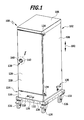
- Fig. 1
- eine schematische perspektivische Darstellung eines Transportwagens mit einer Tür, die durch eine Verschlussvorrichtung in einer Schließstellung zurückgehalten wird;
- Fig. 2
- eine schematische Vorderansicht des Transportwagens aus
Fig. 1 , mit geschlossener Tür; - Fig. 3
- eine schematische perspektivische Darstellung des Transportwagens aus den
Fig. 1 und2 , wobei die Tür nach Freigabe durch die Verschlussvorrichtung in eine vollständig geöffnete Stellung gebracht worden ist; - Fig. 4
- eine schematische Vorderansicht des Transportwagens aus
Fig. 3 , mit vollständig geöffneter Tür; - Fig. 5
- eine vergrößerte Darstellung des Bereichs I aus den
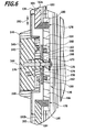
Fig. 1 und2 , mit einem Betätigungselement einer Verschlusssteuerungsvorrichtung des Transportwagens; - Fig. 6
- einen schematischen Längsschnitt durch die Verschlusssteuerungsvorrichtung des Transportwagens;
- Fig. 7
- eine schematische Vorderansicht eines Verschlusssteuerungselements der Verschlusssteuerungsvorrichtung, wobei sich die Verschlusssteuerungsvorrichtung in einer Arretierstellung befindet, in welcher die Verschlusssteuerungsvorrichtung so mit der Verschlussvorrichtung des Transportwagens zusammenwirkt, dass die Verschlussvorrichtung in ihrer Zurückhaltestellung, in welcher sie die Tür in der Schließstellung zurückhält, arretiert ist.
- Fig. 8
- eine schematische Vorderansicht des Verschlusssteuerungselements der Verschlusssteuerungsvorrichtung aus
Fig. 7 , wobei die Verschlusssteuerungsvorrichtung sich in einer Sicherheitsstellung befindet, in welcher die Verschlusssteuerungsvorrichtung so mit der Verschlussvorrichtung zusammenwirkt, dass die Verschlussvorrichtung von ihrer Zurückhaltestellung in eine Freigabestellung bewegbar und die Tür vom Innenraum des Korpus aus zu öffnen ist; - Fig. 9
- eine schematische Vorderansicht des Verschlusselements aus den
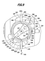
Fig. 7 und8 , wobei die Verschlussteuerungsvorrichtung sich in einer Öffnungsstellung befindet, in welcher die Verschlusssteuerungsvorrichtung so mit der Verschlussvorrichtung zusammenwirkt, dass die Verschlussvorrichtung sich in einer Freigabestellung befindet, in welcher die Tür von innen und/oder von außen zu öffnen ist; - Fig. 10
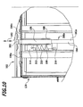
- eine schematische Vorderansicht eines Verschlusselements der Verschlussvorrichtung, wobei die Verschlussvorrichtung sich in der Zurückhaltestellung befindet;
- Fig. 11
- eine der
Fig. 10 entsprechende schematische Vorderansicht des Verschlusselements der Verschlussvorrichtung, wobei die Verschlussvorrichtung sich in der Freigabestellung befindet; - Fig. 12
- einen gegenüber der Darstellung der
Fig. 10 um 90° gedrehten schematischen vertikalen Schnitt durch die Verschlussvorrichtung, wobei die Verschlussvorrichtung sich in der Zurückhaltestellung befindet; und - Fig. 13
- einen gegenüber der Darstellung der
Fig. 11 um 90° gedrehten schematischen vertikalen Schnitt durch die Verschlussvorrichtung, wobei die Verschlussvorrichtung sich in der Freigabestellung befindet. - Gleiche oder funktional äquivalente Elemente sind in allen Figuren mit denselben Bezugszeichen bezeichnet.
- Ein in den
Fig. 1 bis 13 dargestellter, als Ganzes mit 100 bezeichneter Transportwagen, insbesondere ein Speisentransportwagen, beispielsweise ein Bankettwagen, umfasst einen Korpus 102 mit einer Bodenwand 104, mit einer Deckenwand 106, mit zwei die Bodenwand 104 und die Deckenwand 106 miteinander verbindenden vertikalen Seitenwänden 108 und mit einer die beiden Seitenwände 108 und ebenfalls die Bodenwand 104 und die Deckenwand 106 miteinander verbindenden Rückwand (siehe insbesondere dieFig. 1 bis 4 ). - Ein Innenraum 110 des Korpus 102 (siehe die
Fig. 3 und4 ) dient der Aufnahme von Speisenbehältern mit darin aufgenommenen Speisen und/oder Getränkebehältern mit darin aufgenommenen Getränken sowie gegebenenfalls von Tabletts, auf denen solche Speisenbehälter und/oder Getränkebehälter angeordnet werden können. - Um in dem Innenraum 110 jeweils mehrere solcher Speisenbehälter, Getränkebehälter und/oder Tabletts übereinander anordnen zu können, sind die Innenseiten der Seitenwände 108 mit einander paarweise gegenüberliegenden Auflagevorsprüngen 112 versehen, wobei auf jedes Paar einander gegenüberliegender Auflagevorsprünge 112 jeweils ein Speisenbehälter, Getränkebehälter oder Tablett in horizontaler Ausrichtung auflegbar ist.
- Längs der Auflagevorsprünge 112 kann der aufgelegte Behälter oder das aufgelegte Tablett ferner aus dem Innenraum 110 herausgezogen oder in den Innenraum 110 eingeschoben werden.
- Unterhalb der Bodenwand 104 des Korpus 102 ist eine Aufnahmekammer 114 für Bestandteile einer Temperiervorrichtung des Transportwagens 100 angeordnet, welche seitlich und an ihrer Rückseite durch Verlängerungen der Seitenwände 108 bzw. der Rückwand des Korpus 102 und nach vorne hin durch eine Frontplatte 116 begrenzt ist.
- Die Temperiervorrichtung kann eine Kühlvorrichtung zum Kühlen des Innenraums 110 und/oder eine Heizvorrichtung zum Erwärmen des Innenraums 110 des Transportwagens 100 umfassen.
- An der Frontplatte 116 können beispielsweise ein Netzschalter 118 zum Ein-und Ausschalten der Temperiervorrichtung, ein Regler 120 für die Temperiervorrichtung und eine zugentlastende Durchführung 122 für ein (nicht dargestelltes) Netzkabel der Temperiervorrichtung angeordnet sein.
- Die Aufnahmekammer 114 ruht auf einer Plattform 124, die an ihrer Unterseite mit mehreren, beispielsweise vier, Fahrrollen 126 versehen ist, um eine Verfahrbewegung des Transportwagens 100 zu ermöglichen.
- Über die Fahrrollen 126 stützt sich der Transportwagen 100 an einem Untergrund ab.
- Der Innenraum 110 des Korpus 102 ist mittels einer Tür 128 verschließbar.
- Dabei ist in den
Fig. 1 und2 die Tür 128 in einer Schließstellung dargestellt, in welcher die Tür 128 den Innenraum 110 des Korpus 102 verschließt, während die Tür 128 in denFig. 3 und4 in einer von der Schließstellung der Tür 128 verschiedenen Offenstellung der Tür 128 dargestellt ist, in welcher der Innenraum 110 für einen Belade- oder Entladevorgang von außen zugänglich ist. - Insbesondere zeigen die
Fig. 3 und4 eine vollständig geöffnete Stellung der Tür 128, in welcher eine Außenseite der Tür 128 an einer Außenseite einer Seitenwand 108 des Korpus 102 anliegt. - In dieser vollständig geöffneten Stellung ist die Tür 128 gegenüber ihrer Schließstellung um einen Winkel von ungefähr 270° um ihre vertikale Schwenkachse verschwenkt.
- In dieser vollständig geöffneten Stellung ist die Tür 128 mittels einer an der Seitenwand 108 angeordneten Rasteinrichtung 130 verrastbar.
- Ferner kann an einer der Seitenwände 108, beispielsweise unterhalb der Rasteinrichtung 130, eine Aufnahme 132 für einen (nicht dargestellten) Stecker des Netzkabels der Temperiervorrichtung des Transportwagens 100 vorgesehen sein. In diese Aufnahme 132 kann der Stecker des Netzkabels eingesteckt werden, wenn die Temperiervorrichtung, beispielsweise während eines Transportvorgangs des Transportwagens 100, nicht an das Stromnetz angeschlossen ist.
- Die Tür 128 ist an dem Korpus 102 durch Scharniere 134 angelenkt.
- Ferner ist die Tür 128 mit einer Verschlussvorrichtung 136 versehen, welche die Tür 128 in ihrer Schließstellung zurückhält.
- Die Funktion dieser Verschlussvorrichtung 136 wird mittels einer im folgenden noch näher zu beschreibenden Verschlusssteuerungsvorrichtung 138 gesteuert, welche ein an der Tür 128 angeordnetes und von außerhalb des Transportwagens 100 für eine Betätigung zugängliches Betätigungselement 140 umfasst. Die Verschlusssteuerungsvorrichtung 138 mit dem Betätigungselement 140 ist in den
Fig. 5 bis 9 im Detail dargestellt. - Das Betätigungselement 140 umfasst einen Betätigungsgriff 142, der um eine - beispielsweise im Wesentlichen horizontal ausgerichtete - Drehachse 144 der Verschlusssteuerungsvorrichtung 138 drehbar ist (siehe insbesondere
Fig. 6 ). - Der Betätigungsgriff 142 ist in einem ortsfesten Gehäuse 146 aufgenommen, welches eine im Wesentlichen zylindrische Bodenplatte 148 (siehe
Fig. 6 ) und eine von der Bodenplatte 148 nach vorne abstehende, den Betätigungsgriff 142 ringförmig umgebende Umfangswand 150 umfasst. - Das Gehäuse 146 ist in eine Aussparung an der Außenseite der Tür 128 eingesetzt und in dieser Position verrastet.
- Der Betätigungsgriff 142 ist an seiner der Bodenplatte zugewandten Rückseite mit einem Mitnehmervorsprung 152 versehen, welcher eine Durchtrittsöffnung in der Bodenplatte 148 des Gehäuses 146 durchsetzt und an seinem freien Ende als ein Mehrkant 154, beispielsweise als ein Vierkant, ausgebildet ist, der in eine hierzu komplementäre Ausnehmung 156 in einer Mitnahmescheibe 158 eingreift, so dass der Betätigungsgriff 142 und die Mitnahmescheibe 158 drehfest miteinander verbunden und beide relativ zu dem Gehäuse 146 um die Drehachse 144 drehbar sind.
- Die Mitnahmescheibe 158 ist an ihrer dem Gehäuse 146 abgewandten Rückseite mit mehreren Mitnehmerzapfen 160 versehen, welche in hierzu komplementäre Ausnehmungen 162 in einem als Verschlusssteuerungsscheibe 164 ausgebildeten Verschlusssteuerungselement 166 eingreifen, so dass das Verschlusssteuerungselement 166 und die Mitnahmescheibe 158 drehfest miteinander verbunden sind und gemeinsam mit dem Betätigungsgriff 142 um die Drehachse 144 der Verschlusssteuerungsvorrichtung 138 drehbar sind.
- Das Verschlusssteuerungselement 166, die Mitnahmescheibe 158 und der Betätigungsgriff 142 sind ferner in der Axialrichtung der Drehachse 144 durch ein Befestigungsmittel 168, beispielsweise eine Befestigungsschraube, miteinander verbunden.
- Das Befestigungsmittel 168 liegt mit einem Kopfteil 170, vorzugsweise über eine Unterlegscheibe 172, an der der Mitnahmescheibe 158 abgewandten Rückseite des Verschlusssteuerungselements 166 an, durchsetzt mit einem Schaftteil 174 eine Durchtrittsöffnung im Verschlusssteuerungselement 166 und ist mit einem Gewindeteil 176 in eine hierzu komplementäre Gewindesackbohrung des Betätigungsgriffs 142 eingedreht.
- Wie aus den
Fig. 7 bis 9 zu sehen ist, welche Vorderansichten des Verschlusssteuerungselements 166 in verschiedenen Stellungen zeigen, weist das Verschlusssteuerungselement 166 zwei einander bezüglich der Drehachse 144 diametral gegenüberliegende, vorzugsweise bezüglich der Drehachse 144 im Wesentlichen achsensymmetrische, Verschlusssteuerungsöffnungen 178 auf. - Wie am besten aus
Fig. 6 zu ersehen ist, greift in jede der Verschlusssteuerungsöffnungen 178 jeweils ein axialer Endabschnitt 180 eines Verschlussgestänges 182 ein. - Das obere Verschlussgestänge 182a umfasst ferner einen vertikalen Abschnitt 184, welcher sich von dem axialen Endabschnitt 180 aus im Wesentlichen vertikal nach oben erstreckt.
- Wie aus den
Fig. 10 und11 zu ersehen ist, ist am oberen Ende des Verschlussgestänges 182a ein Verschlussriegel 186 festgelegt. - Der Verschlussriegel 186 kann insbesondere durch Verschweißung mit dem Verschlussgestänge 182a verbunden sein.
- Der Verschlussriegel 186 ist zwischen vertikalen Schenkeln 188 eines ersten Führungswinkels 190a und eines zweiten Führungswinkels 190b längs der Vertikalen 192 verschieblich geführt.
- Die Führungswinkel 190a und 190b sind mittels geeigneter Befestigungsmittel, beispielsweise Befestigungsschrauben, an der Oberseite der Tür 128 festgelegt (siehe insbesondere die
Fig. 10 und11 ). - Wie aus den
Fig. 12 und13 zu ersehen ist, weist der Verschlussriegel 186 zwei sich in vertikaler Richtung erstreckende Langlöcher 194 auf, welche von jeweils einem Führungszapfen 196 durchsetzt werden, der sich von dem vertikalen Schenkel 188 des ersten Führungswinkels 190a zu dem vertikalen Schenkel 188 des zweiten Führungswinkels 190b erstreckt. - Die Führungszapfen 196 weisen jeweils einen Durchmesser auf, welcher der Erstreckung des jeweils zugeordneten Langlochs 194 in der horizontalen Richtung entspricht.
- Hierdurch ist der Verschlussriegel 186 exakt nur in der vertikalen Richtung verschieblich geführt.
- Ferner begrenzen die Führungszapfen 196 zusammen mit den jeweils zugeordneten Langlöchern 194 den Verschiebungsweg des Verschlussriegels 186.
- In der in
Fig. 12 dargestellten Zurückhaltestellung der Verschlussvorrichtung 136 liegen die Führungszapfen 196 am unteren Rand des jeweils zugeordneten Langlochs 194 an, so dass der Verschlussriegel 186 sich in seiner oberen Endstellung befindet. - In der in
Fig. 13 dargestellten Freigabestellung der Verschlussvorrichtung 136 liegen die Führungszapfen 196 an dem oberen Rand des jeweils zugeordneten Langlochs 194 an, so dass sich der Verschlussriegel 186 in seiner unteren Endstellung befindet. - Wie am besten aus
Fig. 12 zu ersehen ist, weist der Verschlussriegel 186 eine sich verjüngende Spitze 198 auf, die in der Zurückhaltestellung der Verschlussvorrichtung 136 in eine im Wesentlichen komplementär zur Spitze 198 ausgebildete Aufnahmeausnehmung 200 eines an der Deckenwand 106 des Korpus 102 angeordneten Aufnahmeelements 202 eingreift. - Dabei liegt in der Zurückhaltestellung der Verschlussvorrichtung 136 eine gegen die Vertikale 192 geneigte Anlagefläche 204 der Spitze 198 des Verschlussriegels 186 an einer ebenfalls gegenüber der Vertikalen 192 geneigten Anschlagfläche 206 der Aufnahmeausnehmung 200 an.
- In der in
Fig. 13 dargestellten Freigabestellung der Verschlussvorrichtung 136 ist hingegen die Spitze 198 des Verschlussriegels 186 so weit nach unten zurückgezogen, dass sie nicht mehr in die Aufnahmeausnehmung 200 des Aufnahmeelements 202 eingreift, so dass die Tür 128 aus ihrer Schließstellung herausgeschwenkt werden kann. - Wie am besten aus den
Fig. 10 und11 zu ersehen ist, ist das aus dem Verschlussgestänge 182a und dem Verschlussriegel 186 gebildete obere Verschlusselement 208a der Verschlussvorrichtung 136 mittels eines Vorspannelements 210 elastisch in die Zurückhaltestellung vorgespannt. - Das Vorspannelement 210 ist beispielsweise als eine Zugfeder 212 ausgebildet, deren erstes Ende an einer mit dem ersten Führungswinkel 190a verbundenen ersten Haltelasche 214 und deren zweites Ende an einer mit dem Verschlusselement 208a, insbesondere mit dem oberen Verschlussgestänge 182a, verbundenen zweiten Haltelasche 216 festgelegt ist.
- Da die Zugfeder 212 bestrebt ist, sich zusammenzuziehen und somit den Abstand zwischen der ersten Haltelasche 214 und der zweiten Haltelasche 216 zu verkürzen, spannt die Zugfeder 212 das Verschlusselement 208a in die in den
Fig. 10 und12 dargestellte Zurückhaltestellung der Verschlussvorrichtung 136 vor. - Wie am besten aus den
Fig. 12 und13 zu ersehen ist, ist das obere Verschlusselement 208a mit dem Vorspannelement 210 und den vertikalen Schenkeln 188 der Führungswinkel 190a und 190b im Zwischenraum zwischen einer dem Innenraum 110 des Korpus 102 abgewandten Außenschale 218 und einer dem Innenraum 110 zugewandten Innenschale 220 der Tür 128 angeordnet. - Der Großteil des verbleibenden Zwischenraums zwischen der Außenschale 218 und der Innenschale 220 ist mit einem (nicht dargestellten) Isoliermaterial, beispielsweise einem Polyurethan-Schaum, ausgefüllt.
- Die Außenschale 218 und die Innenschale 220 der Tür 128 sowie der Korpus 102 des Transportwagens 100 sind vorzugsweise aus einem metallischen Material, insbesondere aus einem Edelstahlmaterial, gebildet.
- Die Verschlussvorrichtung 136 umfasst ferner ein unteres Verschlusselement 208b, welches ebenso aufgebaut ist wie das obere Verschlusselement 208a und mit einem Aufnahmeelement an der Bodenwand 104 des Korpus 102 zusammenwirkt, um die Tür 128 in ihrer Schließstellung zurückzuhalten.
- Die Verschlussvorrichtung 136 ist somit als ein Zwei-Punkt-Verschluss ausgebildet.
- Auch das untere Verschlusselement 208b wird mittels eines Vorspannelements 210, beispielsweise in Form einer Zugfeder 212, in die Zurückhaltestellung vorgespannt.
- Vorzugsweise ist das untere Verschlusselement 208b bezüglich der Drehachse 144 der Verschlusssteuerungsvorrichtung 138 achsensymmetrisch zu dem oberen Verschlusselement 208a ausgebildet und angeordnet.
- Die Funktion der Verschlussvorrichtung 136 wird mittels der Verschlusssteuerungsvorrichtung 138 gesteuert, indem das Verschlusssteuerungselement 166 in die in den
Fig. 7 bis 9 dargestellten Positionen gebracht wird. - Dabei liegt das nach oben vorgespannte obere Verschlusselement 208a bei einer Drehung des Verschlusssteuerungselements 166 um die Drehachse 144 mit seinem axialen Endabschnitt 180 am oberen Rand der oberen Verschlusssteuerungsöffnung 178a an, solange keine zusätzliche Kraft auf das obere Verschlusselement 208a einwirkt, so dass dieser obere Rand der oberen Verschlusssteuerungsöffnung 178a eine Verschlusssteuerkurve 222 bildet.
- In entsprechender Weise liegt das untere Verschlusselement 208b mit seinem axialen Endabschnitt 180 an dem unteren Rand der unteren Verschlusssteuerungsöffnung 178b an, solange keine zusätzliche äußere Kraft auf das untere Verschlusselement 208b einwirkt, so dass dieser untere Rand der unteren Verschlusssteuerungsöffnung 178b ebenfalls eine Verschlusssteuerkurve 222 bildet.
- In der in
Fig. 7 dargestellten Arretierstellung der Verschlusssteuerungsvorrichtung 138 befinden sich die axialen Endabschnitte 180 der Verschlusselemente 208a, 208b in einem ersten Endbereich der Verschlusssteuerkurve 222, in welchem die vertikale Ausdehnung der jeweils zugeordneten Verschlusssteuerungsöffnung 178 im Wesentlichen der vertikalen Ausdehnung des axialen Endabschnitts 180 entspricht, so dass die Verschlusselemente 208a und 208b in dieser Arretierstellung nicht in vertikaler Richtung relativ zu dem Verschlusssteuerungselement 166 bewegt werden können, sondern in ihrer in denFig. 10 und12 dargestellten Zurückhaltestellung arretiert sind. In dieser Arretierstellung der Verschlusssteuerungsvorrichtung 138 kann somit die Tür 128 weder von außen noch von innen geöffnet, das heißt von der Schließstellung in eine Offenstellung bewegt, werden. - Die Tür 128 ist somit in dieser Arretierstellung der Verschlusssteuerungsvorrichtung 138 sicher verschlossen, so dass der Transportwagen 100 in dieser Arretierstellung insbesondere sicher transportiert werden kann, ohne dass die Gefahr besteht, dass sich die Tür 128 ungewollt öffnen lässt. Die Tür 128 ist somit in der Arretierstellung sicher verriegelt.
- Um zu verhindern, dass sich die Verschlusssteuerungsvorrichtung 138 unbeabsichtigt aus der Arretierstellung löst, ist eine Arretierstellungs-Rastvorrichtung 224 vorgesehen, welche eine Einbuchtung 226 am Umfang des Verschlusssteuerungselements 266 sowie eine in der Drehrichtung des Verschlusssteuerungselements 166 neben der Einbuchtung 226 liegende Ausbuchtung 228 sowie eine in der Arretierstellung in die Einbuchtung 226 eingreifende Rastnase 230 umfasst.
- Die Rastnase 230 ist in einer an der Tür 128 festgelegten Führungsbuchse 232 in radialer Richtung (bezogen auf die Drehachse 144 des Verschlusssteuerungselements 166) verschieblich geführt und wird mittels eines (nicht dargestellten) Federelements gegen den Umfang des Verschlusssteuerungselements 166 elastisch vorgespannt.
- Um das Verschlusssteuerungselement 166 aus der in
Fig. 7 dargestellten Arretierstellung in die inFig. 8 dargestellte Sicherheitsstellung zu überführen, muss also zunächst die Rückstellkraft des Federelements überwunden werden, welche entsteht, wenn die Rastnase 230 durch die Ausbuchtung 228 am Umfang des Verschlusssteuerungselements 166 radial nach außen gedrückt wird. - Ferner bildet die Führungsbuchse 232 der Arretierstellungs-Rastvorrichtung 224 einen Anschlag für eine Anschlagfläche 234 am Umfang des Verschlussteuerungselements 166, welche in der Arretierstellung an der Führungsbuchse 232 anliegt (siehe
Fig. 7 ), so dass das Verschlusssteuerungselement 166 nicht über die Arretierstellung hinaus (in der Darstellung derFig. 7 im Gegenuhrzeigersinn) gedreht werden kann. - Durch Drehung des Verschlusssteuerungselements 166 mittels des Betätigungselements 140 durch eine Bedienungsperson von außerhalb des Transportwagens 100 ist die Verschlusssteuerungsvorrichtung 138 von der in
Fig. 7 dargestellten Arretierstellung in die inFig. 8 dargestellte Sicherheitsstellung überführbar (im gezeigten Ausführungsbeispiel durch eine Drehung im Uhrzeigersinn). - Aufgrund der Vorspannung der Verschlusselemente 208a und 208b in die Zurückhaltestellung folgen dabei die axialen Endabschnitte 180 der Verschlusselemente 208a und 208b den Verschlusssteuerkurven 222 bis zu einer Ausbuchtung 236 (siehe
Fig. 7 ) der jeweils zugeordneten Verschlusssteuerungsöffnung 178, in welcher der jeweilige axiale Endabschnitt 180 des Verschlusselements 208a bzw. 208b einrastet. - Die Ausbuchtungen 236 bilden somit zusammen mit dem jeweiligen axialen Endabschnitt 180 des zugeordneten Verschlusselements 208a bzw. 208b jeweils eine Sicherheitsstellungs-Rastvorrichtung 238, durch welche die Verschlusssteuerungsvorrichtung 138 in der Sicherheitsstellung verrastbar ist.
- In der Sicherheitsstellung der Verschlusssteuerungsvorrichtung 138 ist die vertikale Ausdehnung der Verschlusssteuerungsöffnungen 178 größer als die vertikale Ausdehnung der axialen Endabschnitte 180 der Verschlusselemente 208a und 208b, so dass die Verschlusselemente 208a und 208b gegen die Rückstellkraft der Vorspannelemente 210 aus der in den
Fig. 10 und12 dargestellten Zurückhaltestellung in die in denFig. 11 und13 dargestellte Freigabestellung bewegt werden können. - Dies kann insbesondere dadurch erfolgen, dass eine im Innenraum 110 des Korpus 102 befindliche Person von innen gegen die Tür 128 drückt. In diesem Fall wird die Spitze 198 jedes Verschlussriegels 186 gegen die geneigte Anschlagfläche 206 der jeweils zugeordneten Aufnahmeausnehmung 200 gedrückt (siehe insbesondere
Fig. 12 ), so dass die geneigte Anschlagfläche 204 der Spitze 198 des jeweiligen Verschlussriegels 186 entlang der Anschlagfläche 206 der Aufnahmeausnehmung 200 nach unten (im Falle des oberen Verschlusselements 208a) bzw. nach oben (im Falle des unteren Verschlusselements 208b) abgleitet, wodurch der Verschlussriegel 186 des oberen Verschlusselements 208a gegen die elastische Rückstellkraft des Vorspannelements 210 (Zugfeder 212) nach unten und der Verschlussriegel 186 des unteren Verschlusselements 108b gegen die elastische Rückstellkraft des Vorspannelements 210 nach oben bewegt wird, bis beide Verschlusselemente 208a und 208b die in denFig. 11 und13 dargestellte Freigabestellung erreicht haben und die Tür 128 in eine Offenstellung bewegbar ist. - Der Verschluss der Tür 128 lässt sich somit in der Sicherheitsstellung der Verschlusssteuerungsvorrichtung 138 gegen die Federkraft der Vorspannelemente 210 durch eine im Innenraum 110 des Korpus 102 des Transportwagens 100 befindliche Person, beispielsweise ein im Innenraum 110 eingeschlossenes spielendes Kind, mittels Ausübung eines Druckes gegen die Tür 128 von innen öffnen.
- Dabei werden die axialen Endabschnitte 180 der Verschlusselemente 208a und 208b in das Innere der jeweils zugeordneten Verschlusssteuerungsöffnung 178, zu der Drehachse 144 hin, bewegt, wodurch die Verschlussvorrichtung 136 von der Zurückhaltestellung in die Freigabestellung überführt und die Tür 128 somit entriegelt wird.
- Durch die Sicherheitsstellungs-Rastvorrichtungen 238 ist die Verschlusssteuerungsvorrichtung 138 in der Sicherheitsstellung arretiert, so dass sie nicht unbeabsichtigt in die Arretierstellung, in welcher kein Öffnen der Tür 128 vom Innenraum 110 aus möglich ist, übergehen kann.
- In der Sicherheitsstellung der Verschlusssteuerungsvorrichtung 138 ist auch ein Schließen der Tür 128, das heißt die Überführung der Tür von einer Offenstellung in die Schließstellung, ohne Weiteres möglich. Bei einem solchen Schließvorgang gleitet eine hintere Anschlagfläche 240 der Spitze 198 des Verschlussriegels 186 an einer vorderen Anschlagfläche 242 des Aufnahmeelements 202 (siehe
Fig. 12 ) ab, um das in der Offenstellung der Tür 128 in die Zurückhaltestellung vorgespannte Verschlusselement 208a bzw. 208b wieder in die Freigabestellung zu bringen, in welcher die Spitze 198 des jeweiligen Verschlusselements 208a, 208b an dem jeweils zugeordneten Aufnahmeelement 202 vorbei bewegt werden kann, bis die Schließstellung der Tür 128 erreicht ist und die Spitze 198 des Verschlussriegels 186 von dem jeweiligen Vorspannelement 210 wieder in die jeweils zugeordnete Aufnahmeausnehmung 200 des Aufnahmeelements 202 hineinbewegt werden kann, um die Tür 128 in ihrer Schließstellung zurückzuhalten. - Von außen kann die Tür 128 dadurch geöffnet werden, dass die Verschlusssteuerungsvorrichtung 138 von der in
Fig. 8 dargestellten Sicherheitsstellung in die inFig. 9 dargestellte Öffnungsstellung überführt wird, und zwar durch Drehen des Betätigungselements 140 von außerhalb des Transportwagens 100 (in der Darstellung derFig. 8 und9 durch eine Drehung im Uhrzeigersinn). Die Verschlusssteuerkurven 222 nähern sich mit wachsendem Abstand von der jeweiligen Ausbuchtung 236, welche die Sicherheitsstellung der Verschlusssteuerungsvorrichtung 138 definiert, immer mehr der Drehachse 144 des Verschlusssteuerungselements 166 an, so dass die Verschlusselemente 208a und 208b mit zunehmendem Drehwinkel immer weiter zur Drehachse 144 hin gezogen werden (gegen die Rückstellkraft der Vorspannelemente 210), bis die axialen Endabschnitte 180 der Verschlusselemente 208a und 208b, wie inFig. 9 dargestellt, einen zweiten Endbereich der Verschlusssteuerkurven 222 erreichen und somit das Verschlusssteuerungselement 166 nicht mehr in derselben Richtung weitergedreht werden kann. - Bei Erreichen dieses zweiten Endbereichs sind die Verschlusselemente 208a und 208b von der in den
Fig. 10 und12 dargestellten Zurückhaltestellung in die in denFig. 11 und13 dargestellte Freigabestellung überführt, in welcher die Tür 128, beispielsweise durch Ziehen am Betätigungsgriff 142, geöffnet werden kann, weil die Spitzen 198 der Verschlussriegel 186 nicht mehr in Eingriff mit den jeweils zugeordneten Aufnahmeausnehmungen 200 stehen. - Wird das Betätigungselement 140 in der in
Fig. 9 dargestellten Öffnungsstellung von der Bedienungsperson losgelassen, so bewirkt die Rückstellkraft der Vorspannelemente 210, dass sich das Verschlusssteuerungselement 166 (im gezeigten Ausführungsbeispiel im Gegenuhrzeigersinn) selbsttätig zurückdreht, bis die Sicherheitsstellung wieder erreicht ist und die axialen Endabschnitte 180 der Verschlusselemente 208a und 208b in der jeweils zugeordneten Ausbuchtung 228 der Verschlusssteuerkurve 222 einrasten. - Bei einer Variante der vorstehend beschriebenen Ausführungsform eines Transportwagens 100 mit integrierter Sicherheitsfunktion zum Öffnen der Tür 128 von innen sind die Vorspannelemente 210 nicht als Zugfedern 212, sondern als Druckfedern ausgebildet, welche bei der Überführung der Verschlussvorrichtung 136 von der Zurückhaltestellung in die Freigabestellung komprimiert werden.
- Ferner kann vorgesehen sein, dass die als Vorspannelemente 210 dienenden Zugfedern oder Druckfedern nicht im korpusseitigen Endbereich der Verschlusselemente 208a und 208b, sondern im Bereich des Verschlusssteuerungselements 166 angeordnet sind.
Claims (16)
- Transportwagen, umfassend einen Korpus (102), mindestens eine Tür (128) und eine Verschlussvorrichtung (136) zum Zurückhalten der Tür (128) in einer Schließstellung der Tür (128) und einer Zurückhaltestellung der Verschlussvorrichtung (136),
dadurch gekennzeichnet,
dass der Transportwagen (100) eine Verschlusssteuerungsvorrichtung (138) umfasst, die eine Arretierstellung aufweist, in welcher die Verschlusssteuerungsvorrichtung (138) so mit der Verschlussvorrichtung (136) zusammenwirkt, dass die Verschlussvorrichtung (136) in ihrer Zurückhaltestellung arretiert ist,
und eine Sicherheitsstellung, in welcher die Verschlusssteuerungsvorrichtung (138) so mit der Verschlussvorrichtung (136) zusammenwirkt, dass die Verschlussvorrichtung (136) von ihrer Zurückhaltestellung in eine Freigabestellung bewegbar und die Tür (128) von einem Innenraum (110) des Korpus (102) aus zu öffnen ist. - Transportwagen nach Anspruch 1, dadurch gekennzeichnet, dass die Tür (128) in der Sicherheitsstellung durch Ausüben eines Drucks auf eine dem Innenraum (110) des Korpus (102) zugewandte Innenseite der Tür (128) zu öffnen ist.
- Transportwagen nach einem der Ansprüche 1 oder 2, dadurch gekennzeichnet, dass der Transportwagen (100) mindestens ein Vorspannelement (210) umfasst, welches in der Sicherheitsstellung der Verschlusssteuerungsvorrichtung (138) die Verschlussvorrichtung (136) in ihre Zurückhaltestellung vorspannt.
- Transportwagen nach Anspruch 3, dadurch gekennzeichnet, dass mindestens ein Vorspannelement (210) ein Federelement umfasst.
- Transportwagen nach einem der Ansprüche 1 bis 4, dadurch gekennzeichnet, dass die Verschlusssteuerungsvorrichtung (138) eine Öffnungsstellung aufweist, in welcher die Verschlusssteuerungsvorrichtung (138) so mit der Verschlussvorrichtung (136) zusammenwirkt, dass die Verschlussvorrichtung (136) sich in einer Freigabestellung befindet, in welcher die Tür von innen und/oder von außen zu öffnen ist.
- Transportwagen nach Anspruch 5, dadurch gekennzeichnet, dass die Verschlusssteuerungsvorrichtung (138) ein Betätigungselement (140) umfasst, das von außerhalb des Transportwagens (100) für eine Betätigung zugänglich ist,
wobei durch Betätigung des Betätigungselements (140) die Verschlusssteuerungsvorrichtung (138) von der Sicherheitsstellung in die Öffnungsstellung überführbar ist. - Transportwagen nach Anspruch 6, dadurch gekennzeichnet, dass die Verschlusssteuerungsvorrichtung (138) durch Drehung eines Verschlusssteuerungselements (166) zwischen der Arretierstellung, der Sicherheitsstellung und der Öffnungsstellung überführbar ist.
- Transportwagen nach einem der Ansprüche 5 bis 7, dadurch gekennzeichnet, dass der Transportwagen (100) mindestens ein Vorspannelement (210) umfasst, welches die Verschlusssteuerungsvorrichtung (138) von der Öffnungsstellung in die Sicherheitsstellung zurückbewegt.
- Transportwagen nach einem der Ansprüche 1 bis 8, dadurch gekennzeichnet, dass die Verschlusssteuerungsvorrichtung (138) ein Betätigungselement (140) umfasst, das von außerhalb des Transportwagens (100) für eine Betätigung zugänglich ist,
wobei durch Betätigung des Betätigungselements (140) die Verschlusssteuerungsvorrichtung (138) von der Sicherheitsstellung in die Arretierstellung und/oder von der Arretierstellung in die Sicherheitsstellung überführbar ist. - Transportwagen nach einem der Ansprüche 1 bis 9, dadurch gekennzeichnet, dass die Verschlusssteuerungsvorrichtung (138) eine Sicherheitsstellungs-Rastvorrichtung (238) zum Verrasten der Verschlusssteuerungsvorrichtung (138) in der Sicherheitsstellung und/oder eine Arretierstellungs-Rastvorrichtung (224) zum Verrasten der Verschlusssteuerungsvorrichtung (138) in der Arretierstellung umfasst.
- Transportwagen nach einem der Ansprüche 1 bis 10, dadurch gekennzeichnet, dass die Verschlussvorrichtung (136) mindestens ein Verschlusselement (208, 208b) umfasst, das in der Zurückhaltestellung der Verschlussvorrichtung (136) so mit dem Korpus (102) zusammenwirkt, dass die Tür (128) in ihrer Schließstellung zurückgehalten wird.
- Transportwagen nach Anspruch 11, dadurch gekennzeichnet, dass die Verschlussvorrichtung (136) mindestens zwei Verschlusselemente (208a, 208b) umfasst, die in der Zurückhaltestellung der Verschlussvorrichtung (136) so mit dem Korpus (102) zusammenwirken, dass die Tür (128) in ihrer Schließstellung zurückgehalten wird,
wobei zwei dieser Verschlusselemente (208a, 208b) sich von der Verschlusssteuerungsvorrichtung (138) aus in einander entgegengesetzte Richtungen erstrecken. - Transportwagen nach Anspruch 12, dadurch gekennzeichnet, dass mindestens zwei Verschlusselemente (208a, 208b) über die Verschlusssteuerungsvorrichtung (138) so miteinander gekoppelt sind, dass sie gleichzeitig in Eingriff und/oder außer Eingriff mit dem Korpus (102) bringbar sind.
- Transportwagen nach einem der Ansprüche 1 bis 13, dadurch gekennzeichnet, dass die Verschlusssteuerungsvorrichtung (138) mindestens ein drehbar gehaltenes Verschlusssteuerungselement (166) umfasst.
- Transportwagen nach Anspruch 14, dadurch gekennzeichnet, dass das Verschlusssteuerungselement (166) mindestens eine Verschlusssteuerkurve (222) umfasst, mit welcher mindestens ein Verschlusselement (208a, 208b) der Verschlussvorrichtung (136) in der Arretierstellung und in der Sicherheitsstellung der Verschlusssteuerungsvorrichtung (138) in Eingriff steht.
- Transportwagen nach Anspruch 15, dadurch gekennzeichnet, dass in der Arretierstellung der Verschlusssteuerungsvorrichtung (138) das Verschlusselement (208a, 208b) nicht relativ zu der Verschlusssteuerkurve (222) bewegbar ist und in der Sicherheitsstellung der Verschlusssteuerungsvorrichtung (138) das Verschlusselement (208a, 208b) relativ zu der Verschlusssteuerkurve (222) bewegbar ist.
Applications Claiming Priority (1)
| Application Number | Priority Date | Filing Date | Title |
|---|---|---|---|
| DE102011002998A DE102011002998A1 (de) | 2011-01-21 | 2011-01-21 | Transportwagen |
Publications (3)
| Publication Number | Publication Date |
|---|---|
| EP2479082A2 true EP2479082A2 (de) | 2012-07-25 |
| EP2479082A3 EP2479082A3 (de) | 2017-11-01 |
| EP2479082B1 EP2479082B1 (de) | 2019-01-02 |
Family
ID=45491425
Family Applications (1)
| Application Number | Title | Priority Date | Filing Date |
|---|---|---|---|
| EP12151143.0A Not-in-force EP2479082B1 (de) | 2011-01-21 | 2012-01-13 | Transportwagen mit Verschlussvorrichtung |
Country Status (3)
| Country | Link |
|---|---|
| EP (1) | EP2479082B1 (de) |
| DE (1) | DE102011002998A1 (de) |
| ES (1) | ES2718615T3 (de) |
Cited By (3)
| Publication number | Priority date | Publication date | Assignee | Title |
|---|---|---|---|---|
| NL2011491C2 (en) * | 2013-09-23 | 2015-03-24 | Alpheios Internat B V | A trolley; and a method for cleaning. |
| US11629905B2 (en) | 2013-01-18 | 2023-04-18 | Triteq Lock And Security, Llc | Cooler lock |
| US11852396B2 (en) | 2013-01-18 | 2023-12-26 | Triteq Lock And Security, Llc | Cooler and freezer lock |
Family Cites Families (6)
| Publication number | Priority date | Publication date | Assignee | Title |
|---|---|---|---|---|
| DE353987C (de) * | 1921-04-20 | 1922-05-29 | Carl Wolff | Sicherung, insbesondere fuer Tueren, mit durch Kurvenscheibe bewegten Haupt- und Nebenriegeln |
| US3057649A (en) * | 1961-03-07 | 1962-10-09 | Yale & Towne Mfg Co | Privacy latch |
| DE2135115A1 (de) * | 1971-07-14 | 1973-02-01 | Huwil Werke Gmbh | Schnaepperverschluss, insbesondere fuer moebeltueren |
| EP0869893B1 (de) * | 1995-10-19 | 1999-08-25 | KLM Catering Services Schiphol B.V. | Vorrichtung und verfahren zur handhabung von, in flugzeugen verwendbaren servierbehältern |
| DE29621218U1 (de) * | 1996-12-06 | 1997-01-23 | BLANCO GmbH + Co KG, 75038 Oberderdingen | Speisen-Transportwagen |
| DE202010000141U1 (de) * | 2010-02-08 | 2010-06-17 | Schwinn Beschläge GmbH | Schnappriegelvorrichtung |
-
2011
- 2011-01-21 DE DE102011002998A patent/DE102011002998A1/de not_active Withdrawn
-
2012
- 2012-01-13 ES ES12151143T patent/ES2718615T3/es active Active
- 2012-01-13 EP EP12151143.0A patent/EP2479082B1/de not_active Not-in-force
Non-Patent Citations (1)
| Title |
|---|
| None |
Cited By (5)
| Publication number | Priority date | Publication date | Assignee | Title |
|---|---|---|---|---|
| US11629905B2 (en) | 2013-01-18 | 2023-04-18 | Triteq Lock And Security, Llc | Cooler lock |
| US11668514B2 (en) | 2013-01-18 | 2023-06-06 | Triteq Lock And Security, Llc | Cooler lock |
| US11852396B2 (en) | 2013-01-18 | 2023-12-26 | Triteq Lock And Security, Llc | Cooler and freezer lock |
| US12235034B2 (en) | 2013-01-18 | 2025-02-25 | Triteq Lock And Security, Llc | Vending lock |
| NL2011491C2 (en) * | 2013-09-23 | 2015-03-24 | Alpheios Internat B V | A trolley; and a method for cleaning. |
Also Published As
| Publication number | Publication date |
|---|---|
| ES2718615T3 (es) | 2019-07-03 |
| EP2479082B1 (de) | 2019-01-02 |
| EP2479082A3 (de) | 2017-11-01 |
| DE102011002998A1 (de) | 2012-07-26 |
Similar Documents
| Publication | Publication Date | Title |
|---|---|---|
| EP2106488B1 (de) | Drehspannverschluss mit betätigungsgriffsicherung | |
| EP2713816B1 (de) | Beschlag für eckschränke | |
| EP2174571A1 (de) | Öffnungsvorrichtung für eine Ausziehführung und Rastmechanismus | |
| DE102017113053A1 (de) | Großladungsträger mit Schwenkklappe | |
| DE19747707A1 (de) | Tankklappe zum Verschließen einer Tankmulde | |
| WO2018059987A1 (de) | Einzugsvorrichtung für einen schubladenauszug | |
| EP2479082B1 (de) | Transportwagen mit Verschlussvorrichtung | |
| DE2743747A1 (de) | Deckelverriegelung an mit ueberdruck betriebenem behaeltnis | |
| EP2850011B1 (de) | Verriegelung für klappe | |
| EP2757218B1 (de) | Behälter mit tür und arretiervorrichtung zum arretieren der tür in einer offenstellung | |
| EP1644221B1 (de) | Sperre zum verhindern einer fehlbedienung einer klappe | |
| EP2138071B1 (de) | Schrank, insbesondere Sicherheitsschrank | |
| EP3015340B1 (de) | Rollcontainer mit entfernbarer seitenwand | |
| DE202015005429U1 (de) | Mischmaschine, insbesondere Baumischmaschine, zum Mischen von Mischgut, insbesondere zum Mischen von Mörteln, Putzen, Estrichen oder Beton | |
| DE556635C (de) | Sicherheitsverschluss fuer einen durch einen abhebbaren Deckel o. dgl. verschliessbaren Behaelter, z. B. fuer eine Waschmaschine | |
| EP3372448B1 (de) | Sicherungseinrichtung | |
| DE10319185B4 (de) | Elektromechanisches Beschlagschloss | |
| EP2732113B1 (de) | Verschluss zum verschliessen einer tür, insbesondere einer gerätetür | |
| DE102008018667A1 (de) | Verriegelungsvorrichtung | |
| DE102017205936B3 (de) | Entsafter | |
| DE102010002542B4 (de) | Transportwagen mit Verschlussvorrichtung und Verriegelungsvorrichtung | |
| EP3560762B1 (de) | Dachtransportvorrichtung | |
| EP3899174A1 (de) | Schloss für ein kraftfahrzeug | |
| EP1383091A1 (de) | Cashbox und Vorrichtung zum Entleeren der Cashbox | |
| DE112014007267T5 (de) | Verriegelungsvorrichtung, umfassend ein gespanntes elastisches Element, das zur Entriegelung der Verriegelungsvorrichtung angeordnet ist |
Legal Events
| Date | Code | Title | Description |
|---|---|---|---|
| PUAI | Public reference made under article 153(3) epc to a published international application that has entered the european phase |
Free format text: ORIGINAL CODE: 0009012 |
|
| AK | Designated contracting states |
Kind code of ref document: A2 Designated state(s): AL AT BE BG CH CY CZ DE DK EE ES FI FR GB GR HR HU IE IS IT LI LT LU LV MC MK MT NL NO PL PT RO RS SE SI SK SM TR |
|
| AX | Request for extension of the european patent |
Extension state: BA ME |
|
| PUAL | Search report despatched |
Free format text: ORIGINAL CODE: 0009013 |
|
| AK | Designated contracting states |
Kind code of ref document: A3 Designated state(s): AL AT BE BG CH CY CZ DE DK EE ES FI FR GB GR HR HU IE IS IT LI LT LU LV MC MK MT NL NO PL PT RO RS SE SI SK SM TR |
|
| AX | Request for extension of the european patent |
Extension state: BA ME |
|
| RIC1 | Information provided on ipc code assigned before grant |
Ipc: E05B 65/10 20060101ALI20170927BHEP Ipc: E05C 9/04 20060101ALI20170927BHEP Ipc: E05C 19/02 20060101ALI20170927BHEP Ipc: E05B 63/22 20060101ALI20170927BHEP Ipc: B62B 3/00 20060101AFI20170927BHEP |
|
| STAA | Information on the status of an ep patent application or granted ep patent |
Free format text: STATUS: REQUEST FOR EXAMINATION WAS MADE |
|
| 17P | Request for examination filed |
Effective date: 20180419 |
|
| RBV | Designated contracting states (corrected) |
Designated state(s): AL AT BE BG CH CY CZ DE DK EE ES FI FR GB GR HR HU IE IS IT LI LT LU LV MC MK MT NL NO PL PT RO RS SE SI SK SM TR |
|
| GRAP | Despatch of communication of intention to grant a patent |
Free format text: ORIGINAL CODE: EPIDOSNIGR1 |
|
| STAA | Information on the status of an ep patent application or granted ep patent |
Free format text: STATUS: GRANT OF PATENT IS INTENDED |
|
| INTG | Intention to grant announced |
Effective date: 20180723 |
|
| RAP1 | Party data changed (applicant data changed or rights of an application transferred) |
Owner name: BLANCO PROFESSIONAL GMBH + CO KG |
|
| GRAS | Grant fee paid |
Free format text: ORIGINAL CODE: EPIDOSNIGR3 |
|
| GRAA | (expected) grant |
Free format text: ORIGINAL CODE: 0009210 |
|
| STAA | Information on the status of an ep patent application or granted ep patent |
Free format text: STATUS: THE PATENT HAS BEEN GRANTED |
|
| AK | Designated contracting states |
Kind code of ref document: B1 Designated state(s): AL AT BE BG CH CY CZ DE DK EE ES FI FR GB GR HR HU IE IS IT LI LT LU LV MC MK MT NL NO PL PT RO RS SE SI SK SM TR |
|
| REG | Reference to a national code |
Ref country code: GB Ref legal event code: FG4D Free format text: NOT ENGLISH |
|
| REG | Reference to a national code |
Ref country code: AT Ref legal event code: REF Ref document number: 1083974 Country of ref document: AT Kind code of ref document: T Effective date: 20190115 Ref country code: CH Ref legal event code: NV Representative=s name: ISLER AND PEDRAZZINI AG, CH Ref country code: CH Ref legal event code: EP |
|
| REG | Reference to a national code |
Ref country code: IE Ref legal event code: FG4D Free format text: LANGUAGE OF EP DOCUMENT: GERMAN |
|
| REG | Reference to a national code |
Ref country code: DE Ref legal event code: R096 Ref document number: 502012014077 Country of ref document: DE |
|
| REG | Reference to a national code |
Ref country code: NL Ref legal event code: MP Effective date: 20190102 |
|
| REG | Reference to a national code |
Ref country code: LT Ref legal event code: MG4D |
|
| PG25 | Lapsed in a contracting state [announced via postgrant information from national office to epo] |
Ref country code: NL Free format text: LAPSE BECAUSE OF FAILURE TO SUBMIT A TRANSLATION OF THE DESCRIPTION OR TO PAY THE FEE WITHIN THE PRESCRIBED TIME-LIMIT Effective date: 20190102 |
|
| REG | Reference to a national code |
Ref country code: ES Ref legal event code: FG2A Ref document number: 2718615 Country of ref document: ES Kind code of ref document: T3 Effective date: 20190703 |
|
| PG25 | Lapsed in a contracting state [announced via postgrant information from national office to epo] |
Ref country code: PL Free format text: LAPSE BECAUSE OF FAILURE TO SUBMIT A TRANSLATION OF THE DESCRIPTION OR TO PAY THE FEE WITHIN THE PRESCRIBED TIME-LIMIT Effective date: 20190102 Ref country code: LT Free format text: LAPSE BECAUSE OF FAILURE TO SUBMIT A TRANSLATION OF THE DESCRIPTION OR TO PAY THE FEE WITHIN THE PRESCRIBED TIME-LIMIT Effective date: 20190102 Ref country code: NO Free format text: LAPSE BECAUSE OF FAILURE TO SUBMIT A TRANSLATION OF THE DESCRIPTION OR TO PAY THE FEE WITHIN THE PRESCRIBED TIME-LIMIT Effective date: 20190402 Ref country code: FI Free format text: LAPSE BECAUSE OF FAILURE TO SUBMIT A TRANSLATION OF THE DESCRIPTION OR TO PAY THE FEE WITHIN THE PRESCRIBED TIME-LIMIT Effective date: 20190102 Ref country code: PT Free format text: LAPSE BECAUSE OF FAILURE TO SUBMIT A TRANSLATION OF THE DESCRIPTION OR TO PAY THE FEE WITHIN THE PRESCRIBED TIME-LIMIT Effective date: 20190502 Ref country code: SE Free format text: LAPSE BECAUSE OF FAILURE TO SUBMIT A TRANSLATION OF THE DESCRIPTION OR TO PAY THE FEE WITHIN THE PRESCRIBED TIME-LIMIT Effective date: 20190102 |
|
| PG25 | Lapsed in a contracting state [announced via postgrant information from national office to epo] |
Ref country code: RS Free format text: LAPSE BECAUSE OF FAILURE TO SUBMIT A TRANSLATION OF THE DESCRIPTION OR TO PAY THE FEE WITHIN THE PRESCRIBED TIME-LIMIT Effective date: 20190102 Ref country code: LV Free format text: LAPSE BECAUSE OF FAILURE TO SUBMIT A TRANSLATION OF THE DESCRIPTION OR TO PAY THE FEE WITHIN THE PRESCRIBED TIME-LIMIT Effective date: 20190102 Ref country code: HR Free format text: LAPSE BECAUSE OF FAILURE TO SUBMIT A TRANSLATION OF THE DESCRIPTION OR TO PAY THE FEE WITHIN THE PRESCRIBED TIME-LIMIT Effective date: 20190102 Ref country code: GR Free format text: LAPSE BECAUSE OF FAILURE TO SUBMIT A TRANSLATION OF THE DESCRIPTION OR TO PAY THE FEE WITHIN THE PRESCRIBED TIME-LIMIT Effective date: 20190403 Ref country code: BG Free format text: LAPSE BECAUSE OF FAILURE TO SUBMIT A TRANSLATION OF THE DESCRIPTION OR TO PAY THE FEE WITHIN THE PRESCRIBED TIME-LIMIT Effective date: 20190402 Ref country code: IS Free format text: LAPSE BECAUSE OF FAILURE TO SUBMIT A TRANSLATION OF THE DESCRIPTION OR TO PAY THE FEE WITHIN THE PRESCRIBED TIME-LIMIT Effective date: 20190502 |
|
| PG25 | Lapsed in a contracting state [announced via postgrant information from national office to epo] |
Ref country code: LU Free format text: LAPSE BECAUSE OF NON-PAYMENT OF DUE FEES Effective date: 20190113 |
|
| REG | Reference to a national code |
Ref country code: DE Ref legal event code: R097 Ref document number: 502012014077 Country of ref document: DE |
|
| REG | Reference to a national code |
Ref country code: BE Ref legal event code: MM Effective date: 20190131 |
|
| REG | Reference to a national code |
Ref country code: IE Ref legal event code: MM4A |
|
| PG25 | Lapsed in a contracting state [announced via postgrant information from national office to epo] |
Ref country code: AL Free format text: LAPSE BECAUSE OF FAILURE TO SUBMIT A TRANSLATION OF THE DESCRIPTION OR TO PAY THE FEE WITHIN THE PRESCRIBED TIME-LIMIT Effective date: 20190102 Ref country code: SK Free format text: LAPSE BECAUSE OF FAILURE TO SUBMIT A TRANSLATION OF THE DESCRIPTION OR TO PAY THE FEE WITHIN THE PRESCRIBED TIME-LIMIT Effective date: 20190102 Ref country code: MC Free format text: LAPSE BECAUSE OF FAILURE TO SUBMIT A TRANSLATION OF THE DESCRIPTION OR TO PAY THE FEE WITHIN THE PRESCRIBED TIME-LIMIT Effective date: 20190102 Ref country code: EE Free format text: LAPSE BECAUSE OF FAILURE TO SUBMIT A TRANSLATION OF THE DESCRIPTION OR TO PAY THE FEE WITHIN THE PRESCRIBED TIME-LIMIT Effective date: 20190102 Ref country code: DK Free format text: LAPSE BECAUSE OF FAILURE TO SUBMIT A TRANSLATION OF THE DESCRIPTION OR TO PAY THE FEE WITHIN THE PRESCRIBED TIME-LIMIT Effective date: 20190102 Ref country code: RO Free format text: LAPSE BECAUSE OF FAILURE TO SUBMIT A TRANSLATION OF THE DESCRIPTION OR TO PAY THE FEE WITHIN THE PRESCRIBED TIME-LIMIT Effective date: 20190102 |
|
| PLBE | No opposition filed within time limit |
Free format text: ORIGINAL CODE: 0009261 |
|
| STAA | Information on the status of an ep patent application or granted ep patent |
Free format text: STATUS: NO OPPOSITION FILED WITHIN TIME LIMIT |
|
| PG25 | Lapsed in a contracting state [announced via postgrant information from national office to epo] |
Ref country code: SM Free format text: LAPSE BECAUSE OF FAILURE TO SUBMIT A TRANSLATION OF THE DESCRIPTION OR TO PAY THE FEE WITHIN THE PRESCRIBED TIME-LIMIT Effective date: 20190102 Ref country code: BE Free format text: LAPSE BECAUSE OF NON-PAYMENT OF DUE FEES Effective date: 20190131 |
|
| 26N | No opposition filed |
Effective date: 20191003 |
|
| PG25 | Lapsed in a contracting state [announced via postgrant information from national office to epo] |
Ref country code: IE Free format text: LAPSE BECAUSE OF NON-PAYMENT OF DUE FEES Effective date: 20190113 |
|
| PG25 | Lapsed in a contracting state [announced via postgrant information from national office to epo] |
Ref country code: SI Free format text: LAPSE BECAUSE OF FAILURE TO SUBMIT A TRANSLATION OF THE DESCRIPTION OR TO PAY THE FEE WITHIN THE PRESCRIBED TIME-LIMIT Effective date: 20190102 |
|
| PGFP | Annual fee paid to national office [announced via postgrant information from national office to epo] |
Ref country code: FR Payment date: 20191216 Year of fee payment: 9 |
|
| PG25 | Lapsed in a contracting state [announced via postgrant information from national office to epo] |
Ref country code: TR Free format text: LAPSE BECAUSE OF FAILURE TO SUBMIT A TRANSLATION OF THE DESCRIPTION OR TO PAY THE FEE WITHIN THE PRESCRIBED TIME-LIMIT Effective date: 20190102 |
|
| PGFP | Annual fee paid to national office [announced via postgrant information from national office to epo] |
Ref country code: GB Payment date: 20200102 Year of fee payment: 9 Ref country code: ES Payment date: 20200203 Year of fee payment: 9 Ref country code: AT Payment date: 20191227 Year of fee payment: 9 Ref country code: IT Payment date: 20200114 Year of fee payment: 9 |
|
| PGFP | Annual fee paid to national office [announced via postgrant information from national office to epo] |
Ref country code: CH Payment date: 20200116 Year of fee payment: 9 |
|
| PG25 | Lapsed in a contracting state [announced via postgrant information from national office to epo] |
Ref country code: MT Free format text: LAPSE BECAUSE OF FAILURE TO SUBMIT A TRANSLATION OF THE DESCRIPTION OR TO PAY THE FEE WITHIN THE PRESCRIBED TIME-LIMIT Effective date: 20190102 |
|
| PGFP | Annual fee paid to national office [announced via postgrant information from national office to epo] |
Ref country code: CZ Payment date: 20201217 Year of fee payment: 10 |
|
| PG25 | Lapsed in a contracting state [announced via postgrant information from national office to epo] |
Ref country code: CY Free format text: LAPSE BECAUSE OF FAILURE TO SUBMIT A TRANSLATION OF THE DESCRIPTION OR TO PAY THE FEE WITHIN THE PRESCRIBED TIME-LIMIT Effective date: 20190102 |
|
| PGFP | Annual fee paid to national office [announced via postgrant information from national office to epo] |
Ref country code: DE Payment date: 20210120 Year of fee payment: 10 |
|
| PG25 | Lapsed in a contracting state [announced via postgrant information from national office to epo] |
Ref country code: HU Free format text: LAPSE BECAUSE OF FAILURE TO SUBMIT A TRANSLATION OF THE DESCRIPTION OR TO PAY THE FEE WITHIN THE PRESCRIBED TIME-LIMIT; INVALID AB INITIO Effective date: 20120113 |
|
| REG | Reference to a national code |
Ref country code: CH Ref legal event code: PL |
|
| REG | Reference to a national code |
Ref country code: AT Ref legal event code: MM01 Ref document number: 1083974 Country of ref document: AT Kind code of ref document: T Effective date: 20210113 |
|
| GBPC | Gb: european patent ceased through non-payment of renewal fee |
Effective date: 20210113 |
|
| PG25 | Lapsed in a contracting state [announced via postgrant information from national office to epo] |
Ref country code: AT Free format text: LAPSE BECAUSE OF NON-PAYMENT OF DUE FEES Effective date: 20210113 Ref country code: FR Free format text: LAPSE BECAUSE OF NON-PAYMENT OF DUE FEES Effective date: 20210131 |
|
| PG25 | Lapsed in a contracting state [announced via postgrant information from national office to epo] |
Ref country code: LI Free format text: LAPSE BECAUSE OF NON-PAYMENT OF DUE FEES Effective date: 20210131 Ref country code: CH Free format text: LAPSE BECAUSE OF NON-PAYMENT OF DUE FEES Effective date: 20210131 Ref country code: GB Free format text: LAPSE BECAUSE OF NON-PAYMENT OF DUE FEES Effective date: 20210113 |
|
| REG | Reference to a national code |
Ref country code: ES Ref legal event code: FD2A Effective date: 20220422 |
|
| PG25 | Lapsed in a contracting state [announced via postgrant information from national office to epo] |
Ref country code: IT Free format text: LAPSE BECAUSE OF NON-PAYMENT OF DUE FEES Effective date: 20210113 |
|
| PG25 | Lapsed in a contracting state [announced via postgrant information from national office to epo] |
Ref country code: MK Free format text: LAPSE BECAUSE OF FAILURE TO SUBMIT A TRANSLATION OF THE DESCRIPTION OR TO PAY THE FEE WITHIN THE PRESCRIBED TIME-LIMIT Effective date: 20190102 |
|
| PG25 | Lapsed in a contracting state [announced via postgrant information from national office to epo] |
Ref country code: ES Free format text: LAPSE BECAUSE OF NON-PAYMENT OF DUE FEES Effective date: 20210114 |
|
| REG | Reference to a national code |
Ref country code: DE Ref legal event code: R119 Ref document number: 502012014077 Country of ref document: DE |
|
| PG25 | Lapsed in a contracting state [announced via postgrant information from national office to epo] |
Ref country code: DE Free format text: LAPSE BECAUSE OF NON-PAYMENT OF DUE FEES Effective date: 20220802 Ref country code: CZ Free format text: LAPSE BECAUSE OF NON-PAYMENT OF DUE FEES Effective date: 20220113 |