EP2479352A2 - Module de stockage d'eau empilable - Google Patents
Module de stockage d'eau empilable Download PDFInfo
- Publication number
- EP2479352A2 EP2479352A2 EP12152122A EP12152122A EP2479352A2 EP 2479352 A2 EP2479352 A2 EP 2479352A2 EP 12152122 A EP12152122 A EP 12152122A EP 12152122 A EP12152122 A EP 12152122A EP 2479352 A2 EP2479352 A2 EP 2479352A2
- Authority
- EP
- European Patent Office
- Prior art keywords
- lid
- base
- reservoir
- water
- overflow
- Prior art date
- Legal status (The legal status is an assumption and is not a legal conclusion. Google has not performed a legal analysis and makes no representation as to the accuracy of the status listed.)
- Granted
Links
Images




Classifications
-
- A—HUMAN NECESSITIES
- A01—AGRICULTURE; FORESTRY; ANIMAL HUSBANDRY; HUNTING; TRAPPING; FISHING
- A01G—HORTICULTURE; CULTIVATION OF VEGETABLES, FLOWERS, RICE, FRUIT, VINES, HOPS OR SEAWEED; FORESTRY; WATERING
- A01G27/00—Self-acting watering devices, e.g. for flower-pots
- A01G27/02—Self-acting watering devices, e.g. for flower-pots having a water reservoir, the main part thereof being located wholly around or directly beside the growth substrate
-
- E—FIXED CONSTRUCTIONS
- E03—WATER SUPPLY; SEWERAGE
- E03B—INSTALLATIONS OR METHODS FOR OBTAINING, COLLECTING, OR DISTRIBUTING WATER
- E03B3/00—Methods or installations for obtaining or collecting drinking water or tap water
- E03B3/02—Methods or installations for obtaining or collecting drinking water or tap water from rain-water
- E03B3/03—Special vessels for collecting or storing rain-water for use in the household, e.g. water-butts
-
- Y—GENERAL TAGGING OF NEW TECHNOLOGICAL DEVELOPMENTS; GENERAL TAGGING OF CROSS-SECTIONAL TECHNOLOGIES SPANNING OVER SEVERAL SECTIONS OF THE IPC; TECHNICAL SUBJECTS COVERED BY FORMER USPC CROSS-REFERENCE ART COLLECTIONS [XRACs] AND DIGESTS
- Y02—TECHNOLOGIES OR APPLICATIONS FOR MITIGATION OR ADAPTATION AGAINST CLIMATE CHANGE
- Y02A—TECHNOLOGIES FOR ADAPTATION TO CLIMATE CHANGE
- Y02A20/00—Water conservation; Efficient water supply; Efficient water use
-
- Y—GENERAL TAGGING OF NEW TECHNOLOGICAL DEVELOPMENTS; GENERAL TAGGING OF CROSS-SECTIONAL TECHNOLOGIES SPANNING OVER SEVERAL SECTIONS OF THE IPC; TECHNICAL SUBJECTS COVERED BY FORMER USPC CROSS-REFERENCE ART COLLECTIONS [XRACs] AND DIGESTS
- Y02—TECHNOLOGIES OR APPLICATIONS FOR MITIGATION OR ADAPTATION AGAINST CLIMATE CHANGE
- Y02A—TECHNOLOGIES FOR ADAPTATION TO CLIMATE CHANGE
- Y02A20/00—Water conservation; Efficient water supply; Efficient water use
- Y02A20/108—Rainwater harvesting
Definitions
- the present invention relates to water storage systems, in particular to water storage systems that are suitable for use in storing rainwater collected by the roofs of buildings.
- such water butts are complex to manufacture, due to their substantial size, and require to be manufactured to a high specification in order to withstand the water pressure experienced at the bottom of such a tall column of water. Due to their size, such water butts are difficult and expensive to transport and store. Additionally, bodies of water of such depth present a safety hazard through presenting a potential drowning risk to children and animals. Further, disadvantageously, where an outlet is provided, such water butts provide only a single outlet tap, close to the bottom of the vessel, which is accordingly inconvenient to use. Yet further, such water butts are typically unattractive, which is a particularly important consideration in a domestic garden setting.
- such wicking arrangements only function effectively when there is a small vertical separation (e.g. a few centimetres) between the growing medium in the planter and the free surface of the water within the water butt. Accordingly, such wicking arrangements do not function effectively when the water level in the water butt drops, either through water being drawn out of the water butt through the tap, or through having been wicked out, bringing the operation of the wicking system into conflict with other uses of the stored water. Further, disadvantageously, such wicking arrangements can only function again when the water butt has been almost completely re-filled, for example by heavy rain, in the case of a system that collects water from a guttering downpipe.
- a small vertical separation e.g. a few centimetres
- watering the plants in the planter requires that water from within the water butt is decanted into a separate vessel (e.g. watering can) which then requires to be raised above the level of the planter to enable the water to be poured onto the top of the planter. Yet further, due to the substantial height of the water butt, it is difficult to successfully mask the appearance of the water butt with foliage trailing down from a planter mounted as a lid above the water butt.
- a separate vessel e.g. watering can
- a stackable water storage module comprising a base portion and a lid portion, wherein
- a water storage system comprising at least two base portions and a lid portion of a stackable water storage module, the module comprising a base portion and a lid portion, wherein
- the present invention provides a water storage vessel in which:
- the base portion and lid portion may be separately formed.
- the base portion may comprise a base portion body and each base portion body may be configured to nest with a further base portion body.
- the lid portion may be configured to nest with a further lid portion.
- the base portion and lid portion may be integrally formed.
- the lid portion may be adapted to receive the planter at an edge of the lid portion.
- the lid portion may have a planter retention feature adapted to facilitate the retention of a planter by the lid portion.
- the planter may be adapted to irrigate a growing medium contained therein by capillary action through growing medium that is provided within a reservoir communication portion of the planter.
- the planter may be provided with a wick adapted to irrigate a growing medium contained therein by wicking water from the lid reservoir into the growing medium.
- the base portion may be provided with a drain tube.
- the entire drain tube may be a flexible tube.
- the drain tube may comprise a flexible tube portion, conveniently at or close to the fixed end of the tube.
- the tube may pivot about its fixed end.
- the lid portion may have a waste overflow port.
- the base portion may have a waste overflow port.
- a waste tube may be connected to a waste overflow port on the lid portion or base portion.
- a waste tube may be connected to collect water directly from a base reservoir overflow.
- the module may comprise a support unit configured to fit with a base portion or a lid portion, the support unit having a water collection element and a support unit outlet tube, wherein the water collection element is adapted to collect water flowing onto the support unit from the base portion or lid portion and channel the water to the support unit outlet tube.
- the outlet of the base reservoir overflow may be laterally offset from the inlet of the lid reservoir overflow in the orientation of normal use.
- the module may be adapted to be interconnected with a further module in a lateral interconnection arrangement.
- the water storage system may comprise a plurality of modules.
- FIGS 1A and 1 B illustrates a cross-sectional view through a water storage system having a stacked pair of water storage modules 100 according to the present invention.
- Each module 100A and 100B has a base 102A and 102B and a lid 104A and 104B.
- Each base 102A and 102B has a base reservoir 106A and 106B for storing water that may be drawn off through a drain tube 108, and a base reservoir overflow 110.
- the base reservoir overflow 110 comprises a channel that passes through the base reservoir 106 to the underside of the base 102A and 102B.
- the lower base 102B has a waste overflow port 112, located above the bottom of the lower base reservoir 106B, but at a lower level than the inlet of the base reservoir overflow 110 (in normal use), from which a waste tube 114 is connected to the local drainage system (not shown).
- the lids 104A and 104B mate with the corresponding tops of the bases 102A and 102B, and have lid reservoirs 116A and 116B for providing water to planters 118 containing a growth medium 120 for plants 122.
- Each lid 104A and 104B also has a lid reservoir overflow 124, comprising a channel that passes through the lid reservoir 116A and 116B to the underside of the lid.
- One or more detachable planters 118 may be attached to each lid 104A and 104B.
- Each base 102A and 102B has a base body 102' provided with an outlet connector 128 to which a drain tube 108 (or a tap or outlet pipe) is connected.
- the drain tube 108 may be a flexible tube with an open end 130 (i.e. free end, distal from the base 102).
- the drain tube may have a flexible tube portion at or close to the fixed end, such that the non-flexible portion further can be lowered and directed.
- the drain tube may have a flexible portion at or close to the open end.
- the drain tube may pivot above its fixed end in order to lower the open end.
- the open end 130 is retained in a raised position above the top of the base reservoir 106A and 106B (i.e. above the level of the inlet to the base reservoir overflow 110) by an attachment means mounted on the lid 104B (or alternatively on the base 102B), such as a bracket 132 (e.g. a "C"-clip bracket).
- an attachment means mounted on the lid 104B or alternatively on the base 102B
- the free end of the drain tube 108 may be provided with an attachment mean, such as a hook moulding that may be engaged with a feature of the lid or base.
- the upper base 102A of a stack of modules 100A and 100B may be provided with a filling port 134, and a filling tube 136 connecting between the filling port 134 and a source of water, such as a downpipe (not shown).
- a source of water such as a downpipe (not shown).
- the sequential cascading of water in an alternating manner through the reservoirs of the lids and bases is achieved by laterally offsetting the outlets of the overflows 110 and 124 from the inlets of the overflows 124 and 110 (respectively) beneath, such that water emitted from an overflow passes into the reservoir beneath, and is directed away from the inlet of the overflow beneath.
- Figure 1A shows only a single planter 118 received on the lid 104B and adjacent the base 102A, and having only a single drain tube 108 located on the opposite side of the base.
- more than one planter may be received on each lid and/or more than one drain tube may be provided on each base.
- the drain tube may be longer than depicted, such that it has a longer reach, for example reaching to planters located on the opposite side of the base from the fixed end of the drain tube. Accordingly, conveniently, the drain tube of a base 102A can be used to water planters that are adjacent or at a lower level.
- the drain tube can comprise a transparent or translucent section of tube, such that the level of water within the corresponding base can be determined by inspection of the water level within the drain tube.
- the lid reservoirs in a stack of modules can be re-filled independently of the base reservoirs. Accordingly, in dry weather, water can be provided to the planters connected to a lid, without a requirement that any of the base reservoirs should be full. Such an arrangement permits the re-filling of the lid reservoirs from the base reservoirs.
- the bases and the lids are shaped such that they can each be stacked in a nested configuration, for ease of transportation and storage.
- Figure 1 B shows an enlarged view of the planter 118 of Figure 1A .
- the base of the planter 118 has a recess 138, which engages with a lip 140 of the lid 104B.
- the recess 138 separates a sealed base portion 142 from a reservoir communication portion 144.
- the reservoir communication portion 144 projects down into the lid reservoir 116, and has apertures to allow the ingress of water from the lid reservoir into the growing medium 120 by capillary action.
- the planter 118 is detachable, such that the planter may conveniently be removed from the lid 104. Removal of the planter 118 may facilitate access to the lid reservoir 116B for re-filling. Additionally, removal of the planter 118 is useful for re-potting plants, and removing the planter to an alternative source of water, if required.
- the design of the planter 118 may be such that it is retained on the lid 104 by its centre of gravity being over the lid. Alternatively, a retention feature may be provided on the lid 104 or base 102 to facilitate the retention of the planter 118 on the lid (e.g. an upper edge of the planter may engage with a retention feature such as a rebate 146 of a base 102).
- the planter may not project into the lid reservoir, but may be provided with a wick that conducts water from the lid reservoir to the growing medium.
- a wicking arrangement may be more effective than in the known prior art arrangements due to the provision of a smaller vertical separation between the growing medium and the free surface of water in the lid reservoir, and the independence of the wicking performance from the fill-level of the base reservoir.
- the upper lid 104A is the same as a the lower lid 104B, it will be appreciated that alternatively a dedicated upper lid may be provided, for example which omits features of the lids used lower in the stack of modulates.
- Modules of the present invention are particularly suited to manufacture by plastic injection moulding.
- the base and lid units 102 and 104 are formed separately.
- the base and lids may be formed integrally, for example by a rotational moulding process.
- the side walls of the bases are spaced further apart at the open end than at the closed end to permit stacking of bases for transport and storage.
- the lids may be stackable.
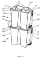
- FIG 2A shows a cut-away perspective view of a stacked pair of modules 100A and 100B, which are similar to those of Figure 1A .
- Wall sections 148 on each lid 104A and 104B fit to each base 102A and are provided to hold the bottom of each base 102A in location on the lid.
- a lip 140 is provided on each lid 104A, which fits to the base 102B and hold the lid in place on the upper rim 152 of each base 102A.
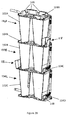
- Figure 2B shows a similar arrangement to Figure 2A , but with a stack of three modules, 100A, 100B and 100C, in which the lowest base 102C stands on a further lid 104D (the lid outlet pipe is now shown).
- Such an arrangement enables one or more further planters to be provided around the bottom of the base of the lowest module in the stack of modules, and enables all of the bases 102A, 102B and 102C to be identical in design, simplifying manufacture, transport and assembly.
- a waste tube is connected directly to the base reservoir overflow to collect overflowing water, and carry it away from the water storage system.
- the lowest base may be raised above the ground on a stand.
- a support unit 154 is provided beneath the lowest base 102C to collect excess water that flows out of the lowest base reservoir, which is provided with a support unit outlet tube 158 to conduct the excess water from the water storage system, as illustrated in Figure 2C . Accordingly, the support unit 154 raises the lowest base 102C above ground level (like a plinth beneath a statue). The lowest base 102C is held in place on the support unit 154, for example by the support unit having peripheral wall sections 148' corresponding with the arrangement of peripheral wall sections 148 on the corresponding lids 104A, 104B and 104C.
- the support unit 154 has a water collection element 156 (e.g.
- a funnel-like element to collect excess water overflowing through the base reservoir overflow 110C, and channel the water through the support unit outlet tube 158.
- this enables all of the lids 104A, 104B and 104C to be of identical design, and to enable more convenient access to the drain tube 108C of the lowest base 102C.
- a support unit may be provided which has a rim that is shaped like that of a base unit, to hold a lid in place on the support unit, such that a lid may be provided between the lower base and the support unit.
- a support unit may be provided which has a rim that is shaped like that of a base unit, to hold a lid in place on the support unit, such that a lid may be provided between the lower base and the support unit.
- Figure 3A shows a perspective view of a stacked pair of modules 100A and 100B, with a pair of planters 118 received onto the lower lid 104B. Further planters 118 can be provided on other sides of the lower lid 104B and around the sides of the upper lid 104A.
- Figure 3B shows a corresponding arrangement in exploded view.
- Figures 1A to 2B only refer to single column stacks of water storage modules, it will be appreciated that further modules may be arranged adjacent the first stack. Accordingly a two- or three-dimensional arrangement of modules may be constructed. The versatility of the modules permits their arrangement into blocks that best suit the space available.
- modules that are on the same level may be interconnected by interconnection tubes (advantageously connecting between ports close to the bottom of the bases). Interconnection ports may be provided in base units to facilitate such interconnection. Accordingly, by use of laterally interconnected modules in a multicolumn arrangement, it is possible to form larger, common bodies of water that can each be drawn out through a common drain tube.
- Figure 4 shows such an arrangement, in the case of a 2x2 array of modules 100A, 100B, 100A' and 100B', in which the upper and lower bases are each respectively interconnected by an interconnection pipe 160, with the drain tubes shown in the raised 108A and 108B and lowered 108A' and 108B' positions.
- water storage modules have been described in the illustrations as comprising a lid that is received onto the top of a base, it will be appreciated that the present invention concerns a modular system, and accordingly a module may equally be considered to comprise a base that is received onto a lid.
Landscapes
- Engineering & Computer Science (AREA)
- Life Sciences & Earth Sciences (AREA)
- Water Supply & Treatment (AREA)
- Environmental & Geological Engineering (AREA)
- Health & Medical Sciences (AREA)
- Hydrology & Water Resources (AREA)
- Public Health (AREA)
- Environmental Sciences (AREA)
- Cultivation Receptacles Or Flower-Pots, Or Pots For Seedlings (AREA)
Applications Claiming Priority (1)
| Application Number | Priority Date | Filing Date | Title |
|---|---|---|---|
| GB1101171.5A GB2487432B (en) | 2011-01-24 | 2011-01-24 | Stackable water storage module |
Publications (3)
| Publication Number | Publication Date |
|---|---|
| EP2479352A2 true EP2479352A2 (fr) | 2012-07-25 |
| EP2479352A3 EP2479352A3 (fr) | 2016-08-17 |
| EP2479352B1 EP2479352B1 (fr) | 2018-07-04 |
Family
ID=43769508
Family Applications (1)
| Application Number | Title | Priority Date | Filing Date |
|---|---|---|---|
| EP12152122.3A Active EP2479352B1 (fr) | 2011-01-24 | 2012-01-23 | Module de stockage d'eau empilable |
Country Status (2)
| Country | Link |
|---|---|
| EP (1) | EP2479352B1 (fr) |
| GB (1) | GB2487432B (fr) |
Cited By (3)
| Publication number | Priority date | Publication date | Assignee | Title |
|---|---|---|---|---|
| WO2014037747A3 (fr) * | 2012-09-07 | 2014-06-26 | Bjorn Wood | Perfectionnements apportés à des dispositifs de stockage d'eau et leurs appareils |
| US9521811B2 (en) | 2013-11-08 | 2016-12-20 | Jack Steve Peterson | Plant tower |
| US9867340B1 (en) * | 2013-06-18 | 2018-01-16 | WaterWell Planters, Inc. | Self-watering two-piece planter |
Families Citing this family (2)
| Publication number | Priority date | Publication date | Assignee | Title |
|---|---|---|---|---|
| GB2587380B (en) * | 2019-09-26 | 2021-12-08 | Bluumbox Ltd | Stackable Watering Can |
| GB2639523A (en) * | 2023-11-30 | 2025-10-01 | Save Water Save Money Ltd | Container for collecting and storing rainwater |
Family Cites Families (8)
| Publication number | Priority date | Publication date | Assignee | Title |
|---|---|---|---|---|
| US3976228A (en) * | 1974-12-05 | 1976-08-24 | Allen Blaine Robbins | Liquid storage system |
| US4779378A (en) * | 1984-02-13 | 1988-10-25 | Mason Jr Stanley I | Integrable, modular stackable multi-plant holder |
| JP2695608B2 (ja) * | 1993-05-21 | 1998-01-14 | 株式会社トーテツ | 雑用水貯留施設 |
| DE20111129U1 (de) * | 2001-07-10 | 2001-10-18 | Bednarsch, Marcus, 98527 Suhl | Regenwasserbehälter mit integriertem Pflanzbehälter |
| CN1819763A (zh) * | 2003-07-30 | 2006-08-16 | 名古屋勉 | 具有自动供水功能的花盆 |
| AU2003904312A0 (en) * | 2003-08-13 | 2003-08-28 | Keats, John Rodney | Plant pot with water reservoir |
| FR2885373B1 (fr) * | 2005-05-03 | 2008-11-21 | Laurent Lachaux | Dispositif permettant de stocker les eaux pluviales |
| FR2908431B1 (fr) * | 2006-11-14 | 2010-02-26 | Jean-Francois Vincent | Citerne-jardiniere |
-
2011
- 2011-01-24 GB GB1101171.5A patent/GB2487432B/en not_active Expired - Fee Related
-
2012
- 2012-01-23 EP EP12152122.3A patent/EP2479352B1/fr active Active
Non-Patent Citations (1)
| Title |
|---|
| None |
Cited By (3)
| Publication number | Priority date | Publication date | Assignee | Title |
|---|---|---|---|---|
| WO2014037747A3 (fr) * | 2012-09-07 | 2014-06-26 | Bjorn Wood | Perfectionnements apportés à des dispositifs de stockage d'eau et leurs appareils |
| US9867340B1 (en) * | 2013-06-18 | 2018-01-16 | WaterWell Planters, Inc. | Self-watering two-piece planter |
| US9521811B2 (en) | 2013-11-08 | 2016-12-20 | Jack Steve Peterson | Plant tower |
Also Published As
| Publication number | Publication date |
|---|---|
| EP2479352B1 (fr) | 2018-07-04 |
| GB2487432A (en) | 2012-07-25 |
| GB201101171D0 (en) | 2011-03-09 |
| GB2487432B (en) | 2013-09-04 |
| EP2479352A3 (fr) | 2016-08-17 |
Similar Documents
| Publication | Publication Date | Title |
|---|---|---|
| CN106572639B (zh) | 模块化容器和模块化灌溉系统 | |
| US11130614B2 (en) | Stackable container | |
| KR101635837B1 (ko) | 빗물 집수 장치 및 이 빗물 집수 장치를 구비한 식물 재배 시스템 | |
| EP2479352B1 (fr) | Module de stockage d'eau empilable | |
| US20090260284A1 (en) | Green roof tray | |
| WO2007063815A1 (fr) | Unite de culture de plantes et conteneur de culture de plantes | |
| US20140083021A1 (en) | Rainwater collection, storage, and distribution system | |
| US20100037517A1 (en) | Plant Cultivation Apparatus with Open Channel Irrigation System | |
| US20150082697A1 (en) | Planter or gardening container | |
| CN104273020A (zh) | 一种浮动水培种植箱 | |
| CN102919078A (zh) | 自吸式自供水花盆 | |
| US9974248B2 (en) | Planter box, multipurpose diacolation pipe and method for soil drainage and irrigation | |
| JP2009082102A (ja) | 緑化ユニットおよび緑化システムならびに植栽ホルダーおよび収納コンテナ | |
| US20150208595A1 (en) | Water Storage Devices and Apparatuses Therefor | |
| WO2017010952A1 (fr) | Tour hydroponique modulaire | |
| CN104115692A (zh) | 蓄排水种植槽 | |
| KR200420135Y1 (ko) | 환경 미화용 분리형 수경화분 | |
| US6993869B2 (en) | Stackable planting containers with capillary watering | |
| CN211631216U (zh) | 一种组合式储水根灌装置 | |
| CN107432218A (zh) | 农业种植装置 | |
| CN212013727U (zh) | 一种立体生态节能种植系统 | |
| CN213463314U (zh) | 一种装配式超轻屋顶绿化系统 | |
| US11516971B2 (en) | Stackable plant pot assembly | |
| JP5149857B2 (ja) | 雨水利用型植物栽培装置 | |
| JP3096586U (ja) | 自動給水連結植木鉢 |
Legal Events
| Date | Code | Title | Description |
|---|---|---|---|
| PUAI | Public reference made under article 153(3) epc to a published international application that has entered the european phase |
Free format text: ORIGINAL CODE: 0009012 |
|
| AK | Designated contracting states |
Kind code of ref document: A2 Designated state(s): AL AT BE BG CH CY CZ DE DK EE ES FI FR GB GR HR HU IE IS IT LI LT LU LV MC MK MT NL NO PL PT RO RS SE SI SK SM TR |
|
| AX | Request for extension of the european patent |
Extension state: BA ME |
|
| PUAL | Search report despatched |
Free format text: ORIGINAL CODE: 0009013 |
|
| AK | Designated contracting states |
Kind code of ref document: A3 Designated state(s): AL AT BE BG CH CY CZ DE DK EE ES FI FR GB GR HR HU IE IS IT LI LT LU LV MC MK MT NL NO PL PT RO RS SE SI SK SM TR |
|
| AX | Request for extension of the european patent |
Extension state: BA ME |
|
| RIC1 | Information provided on ipc code assigned before grant |
Ipc: E03B 3/03 20060101AFI20160708BHEP Ipc: A01G 27/02 20060101ALI20160708BHEP |
|
| STAA | Information on the status of an ep patent application or granted ep patent |
Free format text: STATUS: REQUEST FOR EXAMINATION WAS MADE |
|
| 17P | Request for examination filed |
Effective date: 20170209 |
|
| RBV | Designated contracting states (corrected) |
Designated state(s): AL AT BE BG CH CY CZ DE DK EE ES FI FR GB GR HR HU IE IS IT LI LT LU LV MC MK MT NL NO PL PT RO RS SE SI SK SM TR |
|
| GRAP | Despatch of communication of intention to grant a patent |
Free format text: ORIGINAL CODE: EPIDOSNIGR1 |
|
| STAA | Information on the status of an ep patent application or granted ep patent |
Free format text: STATUS: GRANT OF PATENT IS INTENDED |
|
| INTG | Intention to grant announced |
Effective date: 20170914 |
|
| GRAJ | Information related to disapproval of communication of intention to grant by the applicant or resumption of examination proceedings by the epo deleted |
Free format text: ORIGINAL CODE: EPIDOSDIGR1 |
|
| STAA | Information on the status of an ep patent application or granted ep patent |
Free format text: STATUS: REQUEST FOR EXAMINATION WAS MADE |
|
| GRAP | Despatch of communication of intention to grant a patent |
Free format text: ORIGINAL CODE: EPIDOSNIGR1 |
|
| STAA | Information on the status of an ep patent application or granted ep patent |
Free format text: STATUS: GRANT OF PATENT IS INTENDED |
|
| INTC | Intention to grant announced (deleted) | ||
| INTG | Intention to grant announced |
Effective date: 20180208 |
|
| RAP1 | Party data changed (applicant data changed or rights of an application transferred) |
Owner name: DESIGN 4 PLASTICS LIMITED |
|
| GRAS | Grant fee paid |
Free format text: ORIGINAL CODE: EPIDOSNIGR3 |
|
| GRAA | (expected) grant |
Free format text: ORIGINAL CODE: 0009210 |
|
| STAA | Information on the status of an ep patent application or granted ep patent |
Free format text: STATUS: THE PATENT HAS BEEN GRANTED |
|
| AK | Designated contracting states |
Kind code of ref document: B1 Designated state(s): AL AT BE BG CH CY CZ DE DK EE ES FI FR GB GR HR HU IE IS IT LI LT LU LV MC MK MT NL NO PL PT RO RS SE SI SK SM TR |
|
| REG | Reference to a national code |
Ref country code: GB Ref legal event code: FG4D |
|
| REG | Reference to a national code |
Ref country code: CH Ref legal event code: EP |
|
| REG | Reference to a national code |
Ref country code: AT Ref legal event code: REF Ref document number: 1014660 Country of ref document: AT Kind code of ref document: T Effective date: 20180715 |
|
| REG | Reference to a national code |
Ref country code: IE Ref legal event code: FG4D |
|
| REG | Reference to a national code |
Ref country code: DE Ref legal event code: R096 Ref document number: 602012047983 Country of ref document: DE |
|
| REG | Reference to a national code |
Ref country code: NL Ref legal event code: MP Effective date: 20180704 |
|
| REG | Reference to a national code |
Ref country code: LT Ref legal event code: MG4D |
|
| REG | Reference to a national code |
Ref country code: AT Ref legal event code: MK05 Ref document number: 1014660 Country of ref document: AT Kind code of ref document: T Effective date: 20180704 |
|
| PG25 | Lapsed in a contracting state [announced via postgrant information from national office to epo] |
Ref country code: NL Free format text: LAPSE BECAUSE OF FAILURE TO SUBMIT A TRANSLATION OF THE DESCRIPTION OR TO PAY THE FEE WITHIN THE PRESCRIBED TIME-LIMIT Effective date: 20180704 |
|
| PG25 | Lapsed in a contracting state [announced via postgrant information from national office to epo] |
Ref country code: GR Free format text: LAPSE BECAUSE OF FAILURE TO SUBMIT A TRANSLATION OF THE DESCRIPTION OR TO PAY THE FEE WITHIN THE PRESCRIBED TIME-LIMIT Effective date: 20181005 Ref country code: AT Free format text: LAPSE BECAUSE OF FAILURE TO SUBMIT A TRANSLATION OF THE DESCRIPTION OR TO PAY THE FEE WITHIN THE PRESCRIBED TIME-LIMIT Effective date: 20180704 Ref country code: BG Free format text: LAPSE BECAUSE OF FAILURE TO SUBMIT A TRANSLATION OF THE DESCRIPTION OR TO PAY THE FEE WITHIN THE PRESCRIBED TIME-LIMIT Effective date: 20181004 Ref country code: SE Free format text: LAPSE BECAUSE OF FAILURE TO SUBMIT A TRANSLATION OF THE DESCRIPTION OR TO PAY THE FEE WITHIN THE PRESCRIBED TIME-LIMIT Effective date: 20180704 Ref country code: PL Free format text: LAPSE BECAUSE OF FAILURE TO SUBMIT A TRANSLATION OF THE DESCRIPTION OR TO PAY THE FEE WITHIN THE PRESCRIBED TIME-LIMIT Effective date: 20180704 Ref country code: LT Free format text: LAPSE BECAUSE OF FAILURE TO SUBMIT A TRANSLATION OF THE DESCRIPTION OR TO PAY THE FEE WITHIN THE PRESCRIBED TIME-LIMIT Effective date: 20180704 Ref country code: FI Free format text: LAPSE BECAUSE OF FAILURE TO SUBMIT A TRANSLATION OF THE DESCRIPTION OR TO PAY THE FEE WITHIN THE PRESCRIBED TIME-LIMIT Effective date: 20180704 Ref country code: CZ Free format text: LAPSE BECAUSE OF FAILURE TO SUBMIT A TRANSLATION OF THE DESCRIPTION OR TO PAY THE FEE WITHIN THE PRESCRIBED TIME-LIMIT Effective date: 20180704 Ref country code: RS Free format text: LAPSE BECAUSE OF FAILURE TO SUBMIT A TRANSLATION OF THE DESCRIPTION OR TO PAY THE FEE WITHIN THE PRESCRIBED TIME-LIMIT Effective date: 20180704 Ref country code: IS Free format text: LAPSE BECAUSE OF FAILURE TO SUBMIT A TRANSLATION OF THE DESCRIPTION OR TO PAY THE FEE WITHIN THE PRESCRIBED TIME-LIMIT Effective date: 20181104 Ref country code: NO Free format text: LAPSE BECAUSE OF FAILURE TO SUBMIT A TRANSLATION OF THE DESCRIPTION OR TO PAY THE FEE WITHIN THE PRESCRIBED TIME-LIMIT Effective date: 20181004 |
|
| PG25 | Lapsed in a contracting state [announced via postgrant information from national office to epo] |
Ref country code: LV Free format text: LAPSE BECAUSE OF FAILURE TO SUBMIT A TRANSLATION OF THE DESCRIPTION OR TO PAY THE FEE WITHIN THE PRESCRIBED TIME-LIMIT Effective date: 20180704 Ref country code: ES Free format text: LAPSE BECAUSE OF FAILURE TO SUBMIT A TRANSLATION OF THE DESCRIPTION OR TO PAY THE FEE WITHIN THE PRESCRIBED TIME-LIMIT Effective date: 20180704 Ref country code: HR Free format text: LAPSE BECAUSE OF FAILURE TO SUBMIT A TRANSLATION OF THE DESCRIPTION OR TO PAY THE FEE WITHIN THE PRESCRIBED TIME-LIMIT Effective date: 20180704 Ref country code: AL Free format text: LAPSE BECAUSE OF FAILURE TO SUBMIT A TRANSLATION OF THE DESCRIPTION OR TO PAY THE FEE WITHIN THE PRESCRIBED TIME-LIMIT Effective date: 20180704 |
|
| REG | Reference to a national code |
Ref country code: DE Ref legal event code: R097 Ref document number: 602012047983 Country of ref document: DE |
|
| PG25 | Lapsed in a contracting state [announced via postgrant information from national office to epo] |
Ref country code: RO Free format text: LAPSE BECAUSE OF FAILURE TO SUBMIT A TRANSLATION OF THE DESCRIPTION OR TO PAY THE FEE WITHIN THE PRESCRIBED TIME-LIMIT Effective date: 20180704 Ref country code: EE Free format text: LAPSE BECAUSE OF FAILURE TO SUBMIT A TRANSLATION OF THE DESCRIPTION OR TO PAY THE FEE WITHIN THE PRESCRIBED TIME-LIMIT Effective date: 20180704 Ref country code: IT Free format text: LAPSE BECAUSE OF FAILURE TO SUBMIT A TRANSLATION OF THE DESCRIPTION OR TO PAY THE FEE WITHIN THE PRESCRIBED TIME-LIMIT Effective date: 20180704 |
|
| PLBE | No opposition filed within time limit |
Free format text: ORIGINAL CODE: 0009261 |
|
| STAA | Information on the status of an ep patent application or granted ep patent |
Free format text: STATUS: NO OPPOSITION FILED WITHIN TIME LIMIT |
|
| PG25 | Lapsed in a contracting state [announced via postgrant information from national office to epo] |
Ref country code: SK Free format text: LAPSE BECAUSE OF FAILURE TO SUBMIT A TRANSLATION OF THE DESCRIPTION OR TO PAY THE FEE WITHIN THE PRESCRIBED TIME-LIMIT Effective date: 20180704 Ref country code: DK Free format text: LAPSE BECAUSE OF FAILURE TO SUBMIT A TRANSLATION OF THE DESCRIPTION OR TO PAY THE FEE WITHIN THE PRESCRIBED TIME-LIMIT Effective date: 20180704 Ref country code: SM Free format text: LAPSE BECAUSE OF FAILURE TO SUBMIT A TRANSLATION OF THE DESCRIPTION OR TO PAY THE FEE WITHIN THE PRESCRIBED TIME-LIMIT Effective date: 20180704 |
|
| 26N | No opposition filed |
Effective date: 20190405 |
|
| PG25 | Lapsed in a contracting state [announced via postgrant information from national office to epo] |
Ref country code: SI Free format text: LAPSE BECAUSE OF FAILURE TO SUBMIT A TRANSLATION OF THE DESCRIPTION OR TO PAY THE FEE WITHIN THE PRESCRIBED TIME-LIMIT Effective date: 20180704 Ref country code: MC Free format text: LAPSE BECAUSE OF FAILURE TO SUBMIT A TRANSLATION OF THE DESCRIPTION OR TO PAY THE FEE WITHIN THE PRESCRIBED TIME-LIMIT Effective date: 20180704 |
|
| REG | Reference to a national code |
Ref country code: CH Ref legal event code: PL |
|
| PG25 | Lapsed in a contracting state [announced via postgrant information from national office to epo] |
Ref country code: LU Free format text: LAPSE BECAUSE OF NON-PAYMENT OF DUE FEES Effective date: 20190123 |
|
| REG | Reference to a national code |
Ref country code: BE Ref legal event code: MM Effective date: 20190131 |
|
| PG25 | Lapsed in a contracting state [announced via postgrant information from national office to epo] |
Ref country code: BE Free format text: LAPSE BECAUSE OF NON-PAYMENT OF DUE FEES Effective date: 20190131 |
|
| PG25 | Lapsed in a contracting state [announced via postgrant information from national office to epo] |
Ref country code: LI Free format text: LAPSE BECAUSE OF NON-PAYMENT OF DUE FEES Effective date: 20190131 Ref country code: CH Free format text: LAPSE BECAUSE OF NON-PAYMENT OF DUE FEES Effective date: 20190131 |
|
| PG25 | Lapsed in a contracting state [announced via postgrant information from national office to epo] |
Ref country code: TR Free format text: LAPSE BECAUSE OF FAILURE TO SUBMIT A TRANSLATION OF THE DESCRIPTION OR TO PAY THE FEE WITHIN THE PRESCRIBED TIME-LIMIT Effective date: 20180704 |
|
| PG25 | Lapsed in a contracting state [announced via postgrant information from national office to epo] |
Ref country code: PT Free format text: LAPSE BECAUSE OF FAILURE TO SUBMIT A TRANSLATION OF THE DESCRIPTION OR TO PAY THE FEE WITHIN THE PRESCRIBED TIME-LIMIT Effective date: 20181105 Ref country code: MT Free format text: LAPSE BECAUSE OF NON-PAYMENT OF DUE FEES Effective date: 20190123 |
|
| PG25 | Lapsed in a contracting state [announced via postgrant information from national office to epo] |
Ref country code: CY Free format text: LAPSE BECAUSE OF FAILURE TO SUBMIT A TRANSLATION OF THE DESCRIPTION OR TO PAY THE FEE WITHIN THE PRESCRIBED TIME-LIMIT Effective date: 20180704 |
|
| PG25 | Lapsed in a contracting state [announced via postgrant information from national office to epo] |
Ref country code: HU Free format text: LAPSE BECAUSE OF FAILURE TO SUBMIT A TRANSLATION OF THE DESCRIPTION OR TO PAY THE FEE WITHIN THE PRESCRIBED TIME-LIMIT; INVALID AB INITIO Effective date: 20120123 |
|
| PG25 | Lapsed in a contracting state [announced via postgrant information from national office to epo] |
Ref country code: MK Free format text: LAPSE BECAUSE OF FAILURE TO SUBMIT A TRANSLATION OF THE DESCRIPTION OR TO PAY THE FEE WITHIN THE PRESCRIBED TIME-LIMIT Effective date: 20180704 |
|
| PGFP | Annual fee paid to national office [announced via postgrant information from national office to epo] |
Ref country code: GB Payment date: 20260119 Year of fee payment: 15 |
|
| PGFP | Annual fee paid to national office [announced via postgrant information from national office to epo] |
Ref country code: DE Payment date: 20260121 Year of fee payment: 15 Ref country code: IE Payment date: 20260120 Year of fee payment: 15 |
|
| PGFP | Annual fee paid to national office [announced via postgrant information from national office to epo] |
Ref country code: FR Payment date: 20260128 Year of fee payment: 15 |