EP2479371A2 - Profilstange, die an einer Platte befestigt wird, und Plattensystem - Google Patents
Profilstange, die an einer Platte befestigt wird, und Plattensystem Download PDFInfo
- Publication number
- EP2479371A2 EP2479371A2 EP12397503A EP12397503A EP2479371A2 EP 2479371 A2 EP2479371 A2 EP 2479371A2 EP 12397503 A EP12397503 A EP 12397503A EP 12397503 A EP12397503 A EP 12397503A EP 2479371 A2 EP2479371 A2 EP 2479371A2
- Authority
- EP
- European Patent Office
- Prior art keywords
- panel
- slot
- profile bar
- locking
- locking piece
- Prior art date
- Legal status (The legal status is an assumption and is not a legal conclusion. Google has not performed a legal analysis and makes no representation as to the accuracy of the status listed.)
- Granted
Links
Images




Classifications
-
- E—FIXED CONSTRUCTIONS
- E06—DOORS, WINDOWS, SHUTTERS, OR ROLLER BLINDS IN GENERAL; LADDERS
- E06B—FIXED OR MOVABLE CLOSURES FOR OPENINGS IN BUILDINGS, VEHICLES, FENCES OR LIKE ENCLOSURES IN GENERAL, e.g. DOORS, WINDOWS, BLINDS, GATES
- E06B3/00—Window sashes, door leaves, or like elements for closing wall or like openings; Layout of fixed or moving closures, e.g. windows in wall or like openings; Features of rigidly-mounted outer frames relating to the mounting of wing frames
- E06B3/32—Arrangements of wings characterised by the manner of movement; Arrangements of movable wings in openings; Features of wings or frames relating solely to the manner of movement of the wing
- E06B3/34—Arrangements of wings characterised by the manner of movement; Arrangements of movable wings in openings; Features of wings or frames relating solely to the manner of movement of the wing with only one kind of movement
- E06B3/42—Sliding wings; Details of frames with respect to guiding
- E06B3/46—Horizontally-sliding wings
-
- E—FIXED CONSTRUCTIONS
- E04—BUILDING
- E04F—FINISHING WORK ON BUILDINGS, e.g. STAIRS, FLOORS
- E04F11/00—Stairways, ramps, or like structures; Balustrades; Handrails
- E04F11/18—Balustrades; Handrails
- E04F11/181—Balustrades
- E04F11/1851—Filling panels, e.g. concrete, sheet metal panels
- E04F11/1853—Glass panels
-
- E—FIXED CONSTRUCTIONS
- E06—DOORS, WINDOWS, SHUTTERS, OR ROLLER BLINDS IN GENERAL; LADDERS
- E06B—FIXED OR MOVABLE CLOSURES FOR OPENINGS IN BUILDINGS, VEHICLES, FENCES OR LIKE ENCLOSURES IN GENERAL, e.g. DOORS, WINDOWS, BLINDS, GATES
- E06B3/00—Window sashes, door leaves, or like elements for closing wall or like openings; Layout of fixed or moving closures, e.g. windows in wall or like openings; Features of rigidly-mounted outer frames relating to the mounting of wing frames
- E06B3/54—Fixing of glass panes or like plates
- E06B3/5436—Fixing of glass panes or like plates involving holes or indentations in the pane
-
- E—FIXED CONSTRUCTIONS
- E06—DOORS, WINDOWS, SHUTTERS, OR ROLLER BLINDS IN GENERAL; LADDERS
- E06B—FIXED OR MOVABLE CLOSURES FOR OPENINGS IN BUILDINGS, VEHICLES, FENCES OR LIKE ENCLOSURES IN GENERAL, e.g. DOORS, WINDOWS, BLINDS, GATES
- E06B3/00—Window sashes, door leaves, or like elements for closing wall or like openings; Layout of fixed or moving closures, e.g. windows in wall or like openings; Features of rigidly-mounted outer frames relating to the mounting of wing frames
- E06B3/54—Fixing of glass panes or like plates
- E06B3/5454—Fixing of glass panes or like plates inside U-shaped section members
-
- E—FIXED CONSTRUCTIONS
- E06—DOORS, WINDOWS, SHUTTERS, OR ROLLER BLINDS IN GENERAL; LADDERS
- E06B—FIXED OR MOVABLE CLOSURES FOR OPENINGS IN BUILDINGS, VEHICLES, FENCES OR LIKE ENCLOSURES IN GENERAL, e.g. DOORS, WINDOWS, BLINDS, GATES
- E06B7/00—Special arrangements or measures in connection with doors or windows
- E06B7/16—Sealing arrangements on wings or parts co-operating with the wings
-
- E—FIXED CONSTRUCTIONS
- E05—LOCKS; KEYS; WINDOW OR DOOR FITTINGS; SAFES
- E05Y—INDEXING SCHEME ASSOCIATED WITH SUBCLASSES E05D AND E05F, RELATING TO CONSTRUCTION ELEMENTS, ELECTRIC CONTROL, POWER SUPPLY, POWER SIGNAL OR TRANSMISSION, USER INTERFACES, MOUNTING OR COUPLING, DETAILS, ACCESSORIES, AUXILIARY OPERATIONS NOT OTHERWISE PROVIDED FOR, APPLICATION THEREOF
- E05Y2900/00—Application of doors, windows, wings or fittings thereof
- E05Y2900/10—Application of doors, windows, wings or fittings thereof for buildings or parts thereof
- E05Y2900/13—Type of wing
- E05Y2900/148—Windows
- E05Y2900/15—Balcony glazing
-
- E—FIXED CONSTRUCTIONS
- E06—DOORS, WINDOWS, SHUTTERS, OR ROLLER BLINDS IN GENERAL; LADDERS
- E06B—FIXED OR MOVABLE CLOSURES FOR OPENINGS IN BUILDINGS, VEHICLES, FENCES OR LIKE ENCLOSURES IN GENERAL, e.g. DOORS, WINDOWS, BLINDS, GATES
- E06B3/00—Window sashes, door leaves, or like elements for closing wall or like openings; Layout of fixed or moving closures, e.g. windows in wall or like openings; Features of rigidly-mounted outer frames relating to the mounting of wing frames
- E06B3/54—Fixing of glass panes or like plates
- E06B3/58—Fixing of glass panes or like plates by means of borders, cleats, or the like
- E06B3/5807—Fixing of glass panes or like plates by means of borders, cleats, or the like not adjustable
- E06B3/5842—Fixing of glass panes or like plates by means of borders, cleats, or the like not adjustable fixed by a tongue-and-groove or mortise-and-tenon connection substantially parallel to the pane
-
- F—MECHANICAL ENGINEERING; LIGHTING; HEATING; WEAPONS; BLASTING
- F16—ENGINEERING ELEMENTS AND UNITS; GENERAL MEASURES FOR PRODUCING AND MAINTAINING EFFECTIVE FUNCTIONING OF MACHINES OR INSTALLATIONS; THERMAL INSULATION IN GENERAL
- F16B—DEVICES FOR FASTENING OR SECURING CONSTRUCTIONAL ELEMENTS OR MACHINE PARTS TOGETHER, e.g. NAILS, BOLTS, CIRCLIPS, CLAMPS, CLIPS OR WEDGES; JOINTS OR JOINTING
- F16B2200/00—Constructional details of connections not covered for in other groups of this subclass
- F16B2200/60—Coupler sealing means
-
- Y—GENERAL TAGGING OF NEW TECHNOLOGICAL DEVELOPMENTS; GENERAL TAGGING OF CROSS-SECTIONAL TECHNOLOGIES SPANNING OVER SEVERAL SECTIONS OF THE IPC; TECHNICAL SUBJECTS COVERED BY FORMER USPC CROSS-REFERENCE ART COLLECTIONS [XRACs] AND DIGESTS
- Y10—TECHNICAL SUBJECTS COVERED BY FORMER USPC
- Y10T—TECHNICAL SUBJECTS COVERED BY FORMER US CLASSIFICATION
- Y10T403/00—Joints and connections
- Y10T403/47—Molded joint
- Y10T403/472—Molded joint including mechanical interlock
-
- Y—GENERAL TAGGING OF NEW TECHNOLOGICAL DEVELOPMENTS; GENERAL TAGGING OF CROSS-SECTIONAL TECHNOLOGIES SPANNING OVER SEVERAL SECTIONS OF THE IPC; TECHNICAL SUBJECTS COVERED BY FORMER USPC CROSS-REFERENCE ART COLLECTIONS [XRACs] AND DIGESTS
- Y10—TECHNICAL SUBJECTS COVERED BY FORMER USPC
- Y10T—TECHNICAL SUBJECTS COVERED BY FORMER US CLASSIFICATION
- Y10T403/00—Joints and connections
- Y10T403/70—Interfitted members
- Y10T403/7075—Interfitted members including discrete retainer
Definitions
- the invention relates to a profile bar to be locked to a panel, and a panel system, and a method for fixing a panel to a profile bar.
- Glazing systems of prior art which are used, among other things, in balconies, are installed in buildings.
- the systems typically comprise an upper profile and a lower profile, which are used as guide tracks and inside which the necessary movable guide track parts are placed, between which, in turn, the single glass panes are suspended.
- the glass panes form walls and doors, as well as limit a space or protect it, for example, from weather conditions, for example on balconies or terraces, or divide the space into several parts and section off spaces, for example in rooms or business facilities.
- the profiles extend in the horizontal direction and are fixed to the structures of the building.
- the panels typically comprise profile bars which are normally provided at both the upper edge and the lower edge of the panel.
- the profile bar is normally an aluminium profile made by extrusion.
- the guide track parts and, if necessary, also guides, are attached to the profile bar.
- the profile bars are normally fixed to the panels in such a way that the panel is placed in a slot in the profile bar, and the profile bar is kept in place by compression.
- the fixing is also secured by means of glue and fixing members, for example screws, extending through a hole made in the panel.
- the panel is provided with one or more grooves
- the profile bar is provided with a corresponding protrusion
- the panel can be installed by inserting the panel in the profile bar (or the profile bar in the panel) in the longitudinal direction of the profile bar, wherein the protrusion remains to support the panel.
- the profile bar comprises a flexible locking mechanism, in which case the panel can be installed in the profile bar by inserting it transversely to the longitudinal direction of the profile bar.
- the dimensions of the slot or channel in the profile bar are fitted for a panel with a given thickness. Therefore, the same profile bar cannot be applied in different uses, in which the thickness of the panels, for example glass panes, is different. Furthermore, if a rigid profile bar is used, the profile bar must be inserted in the panel in the longitudinal direction, which takes time, particularly if the panel is wide. On the other hand, if the profile bar comprises a flexible locking mechanism, some force is required to install the panel by pressing it into the profile bar.
- the reliable fixing of the profile bar to the panel is important.
- the fixing can be enhanced by gluing.
- the fixing may be incomplete until the glue has dried, and in the meantime the panel may still be transported and stored. There is a risk that the profile bar glides along the panel, moving in the longitudinal direction of the profile bar.
- the aim is to secure that the profile bar remains fixed to the panel as firmly as possible.
- good use is also made of an end plug for the profile bar, preferably two end plugs.
- a profile bar according to the invention, to be locked to a panel, is presented in claim 1.
- a panel system according to the invention is presented in claim 10.
- the solution to be presented will enable the fixing of the profile bar to glass panes or panels in a way that is easy and quick in view of the installation.
- a separate locking piece is applied, which is installed in the profile bar and which keeps the panel fixed.
- the slot or corresponding long channel in the profile bar may be greater in width than the thickness of the panel, to facilitate the installation of the panel.
- the end plug belonging to the profile bar can be locked in place by means of the locking piece.
- the profile bar to be locked can be removed and, if necessary, also disassembled in a very simple way. According to an example of the presented solution, it is now easier to remove the panel and the profile bar, in spite of, for example, gluing.
- the panel can also be kept fixed to the profile bar when the glue securing the fixing has not yet dried, that is, when its holding force is not at the greatest.
- the panel is placed between two locked end plugs in such a way that the panel cannot move from its position. The movement is prevented in at least the longitudinal direction of the profile bar.
- a particular advantage is that the profile bar can be fixed to the panel without making holes in the panel or in the profile bar, and separate fixing members, such as screws, will not be needed. Also, for example screws are not needed for fixing the end plug to be installed at the end of the profile bar.
- glass panes or panels of different thicknesses can be installed partly in the same profile bar.
- the width of the locking piece is selected according to the thickness of the panel. This is useful in view of the manufacturing technique, and it will not be necessary to make several different profile bars.
- the arrangement according to the examples can be applied in glazing systems which are used outdoors or indoors.
- the invention can also be applied in various systems in which different panels and similar plate-like materials are utilized.
- Panel systems are used for protecting or delimiting a space; for example, a balcony can be shielded with glass panels (balcony glazing), or panels can be used in offices for demarcating the personal work space of an employee.
- the system normally comprises several successive panels which are movable.
- the panels are normally rectangular, wherein they are normally in an upright position and form a closed wall or a large window when placed one after the other. They can be connected to guide tracks and be movable in the direction of these guide tracks, typically in the horizontal direction.
- the panels are fixed to profile bars which are, in turn, fixed to the guide tracks by members which are movable in the guide track.
- Figure 1 a shows a panel 100 according to the prior art in an end view.
- the panel is provided with a groove 101 for locking the panel in position.
- the groove 101 is parallel to the side of the panel and its edge, and said side is placed in the frame 110 of a profile bar ( Fig. 1 b) .
- the panel has a first side 100a and an opposite second side 100b, which sides are parallel.
- the groove 101 of the panel is provided on the first side of the panel.
- Figure 1 b shows an end view of a profile bar according to prior art.
- the profile bar comprises a slot 111 or a corresponding channel, in which the panel 100 will be installed.
- the profile bar comprises at least one protrusion 112 which protrudes from the side 111c of the slot and can be fitted in the groove 101 of the panel.
- the profile bar also comprises a second slot 115 which, in a typical use, receives other parts of the panel system, such as hinge pins or the like, which are typically fixed to the above-described guide tracks in the system.
- the profile bar may further comprise at least one groove 113 which is placed in the slot.
- the purpose of the groove 113 is to function as an area where a sealing or adhesive compound, such as silicone or glue 114, can be positioned to seal or strengthen the joint between the profile bar and the panel.
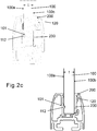
- Figures 2a, 2b , and 2c each show two examples of the structures of the profile bar.
- Figure 2a shows the frame 110 of a profile bar according to an example.
- the frame 110 comprises a slot 111 in which the panel is installed.
- the slot comprises a first side 111 a and a second side 111 b on the opposite side of the slot, to delimit the slot.
- the sides of the slot are, for example, surfaces or walls or other structures which delimit the slot and support the pieces to be placed in the slot, particularly a planar panel.
- the first side 111 a of the slot is placed onto the first side 100a of the panel (see Fig. 2c ), and the second side 111 b of the slot is placed onto the second side 100b of the panel. Because the panel is locked in the slot 111 and the profile bar is fixed to the rest of the system, the slot must be mechanically sturdy. In other words, both sides 111 a and 111 b of the slot are arranged to support the panel mechanically.
- the frame 110 of the profile bar comprises at least one protrusion 112 by which the panel 100 is locked to the profile bar.
- This protrusion is placed on the first side 111 a of the slot.
- the frame may be provided with at least one groove 113 for positioning an adhesive or sealing compound.
- this groove is also on the first side 111 a of the slot.
- Figure 2a only shows a cross-sectional view of the frame of the profile bar. In the direction perpendicular to the plane of the figure, the longitudinal direction of the profile bar, the profile shape of the frame is continuous as shown in Fig. 5d .
- Such a frame may be made, for example, by extrusion, wherein the profile shape is naturally continuous.
- the upper edge of the slot forms an elongated opening 116, in which the panel is installed.
- the opening 116 of the slot 111 is indicated with a straight broken line.
- the frame 110 also comprises at least one fixing member 120, by means of which a locking piece 200 ( Figs. 2b and 2c ) is locked to the profile bar or is held tightly in position.
- the fixing member 120 may be a protrusion, a groove, or a shape, in which a corresponding groove, protrusion or shape of the locking piece 200 is arranged to be received.
- the fixing member 120 shown in Fig. 2a is a protrusion, and for the sake of illustration, it is encircled with broken lines in the figure.
- the profile bar also comprises a separate locking piece 200, one embodiment being shown in Fig. 2b .
- the locking piece comprises at least a locking part 230 for locking the panel in the profile bar.
- the locking part 230 may be planar, and it has a first surface 230a and an opposite second surface 230b.
- the function of the locking part 230 is to make the slot 111 narrower so that the width of the slot made narrower matches the thickness of the panel 100.
- the locking piece, particularly its locking part 230 pushes the panel against the protrusion 112.
- Another function of the locking part 230 is to transmit the supporting forces of the second side 111 b of the slot to the panel.
- the locking piece may also comprise one or more fixing members 210 for fixing the locking piece 200 to the frame 110.
- the fixing member 210 may be, for example, a groove, a protrusion, or a shape.
- a protrusion 220 Fig. 4
- a flexible bulge or protrusion 213 Fig. 2b
- a shape 211 The shape of the locking piece 200 is preferably continuous in the longitudinal direction of the profile bar, and the locking piece may be made, for example, by extrusion.
- the length of the locking piece is preferably equal to or slightly shorter than the length of the panel or the profile bar, depending on e.g. the shape of the end piece 520 ( Fig. 5b ). It is also possible, in some embodiments, to use a shorter locking piece or perhaps several shorter locking pieces in succession.
- Figure 2c illustrates the locked joint of the panel 100 and the profile bar.
- the first side 111 a of the slot supports the panel mechanically.
- the protrusion 112 is in the groove 101 of the panel.
- the first surface 230a of the locking part 230 and the second side 111 b of the slot are abutting so that the locking part 230 transmits the supporting forces of the second side 111 b of the slot to the panel.
- the second surface 100b of the panel is in contact with the second surface 230b of the locking part, so that the mechanical support given by the slot is transmitted to the panel. It is also possible to provide the panel with several grooves and the side wall of the slot with several protrusions, so that several grooves could receive one bulge each.
- the purpose of the locking piece 200 is not particularly to tension the panel 100 in the slot 111, so that the locking piece 230 in the presented example is not wedge-like but has a substantially constant thickness.
- the tip of the locking part 230 may be tapered to facilitate the insertion of the locking piece between the panel 100 and the frame 110 in a way to be described below.
- one function of the locking part 230 is to transmit the supporting forces of the second side 111 b of the slot to the panel. So that these supporting forces would be transmitted further to the second surface 100b of the panel, the total thickness of the locking part 230 and the panel should be substantially equal to the width w of the slot ( Fig. 2a ).
- the width w of the slot 111 is slightly greater than the thickness t of the panel 100 ( Fig. 2c ), to facilitate the installation of the panel 100 in the slot.
- the width of the slot is preferably at least equal to the thickness t of the panel.
- the width w of the slot is greater than the thickness t of the panel by at least the height h of the protrusion 112. These dimensions are illustrated in Figs. 2a and 2c .
- the width of the slot may also be significantly greater than this, in which case the thickness of the locking piece 230 is greater accordingly.
- the protrusion is implemented with a flexible structure or protrusion as shown in Fig. 1 b.
- the height of the protrusion refers to the height of the protrusion in relation to the side of the slot, for example, in relation to the corresponding side wall, as shown in Fig. 1b .
- this side of the lot is denoted with the reference numeral 111 c, and the height of the protrusion 112 with the letter h.
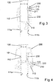
- Figure 3 shows another embodiment of the profile bar, as well as a panel 100 connected to this profile bar.
- the groove 101 of the panel receives the protrusion 112 on the first side of the slot of the frame 110, locking the panel in such a way that the panel cannot move up in Fig. 3 and out of the slot.
- the panel is locked in the slot with a locking piece 200 so that the panel cannot move in the slot in a direction perpendicular to its plane.
- the locking part 230 of the locking piece is arranged between the panel and the second side of the slot, and the thickness of the locking part 230 is fitted to correspond to the difference between the width of the slot and the thickness of the panel.
- the thickness of the panel is greater than in the example of Fig.
- the locking member 210 of the locking pieces consists of a locking shape 211 in which the fixing member 120 of the frame 110 is placed and keeps the locking piece in position.
- the fixing member 120 of the frame is a protrusion having a shape matching to the locking piece and keeping the locking piece in position.
- Figure 4 shows a third embodiment of the profile bar as well as a panel 100 connected to this profile bar.
- the locking part 230 of the locking piece 200 is fitted between the second surface 100b of the panel and the second side 111 b of the slot, and the protrusion 112 on the first side of the slot is received in the groove 101 on the first surface 100a of the panel.
- the second side of the slot is slightly lower than in the preceding embodiments. For this reason, the shape of the locking piece 200 is different and extends higher than the second side of the slot.
- the locking piece 200 comprises a fixing member 210 which is a flexible protrusion 220 in this example.
- the protrusion 220 is placed in a fixing member 120 which is provided in the frame 110 and is also a protrusion having, in turn, a shape that matches the protrusion 220.
- the fixing member 120 keeps the locking piece 200 in position. It is also possible to implement matching shapes between the locking part 230 and the second side of the slot, to increase friction or to keep the locking part 200 in position in the slot and against the panel.
- the fixing member 120 is not at the edge of the slot, preferably on the second side of the slot, as in the example of Fig. 2c or 3 , for instance.
- the fixing member 120 of the frame and, correspondingly, also the fixing member 210 of the locking piece are placed on the outer side of the frame.
- the locking piece 200 constitutes a major part of the visible outer surface and the design of the profile bar.
- the thickness of the locking piece 200 can also be used to select the thickness of the panel to be used in the profile bar. It is also possible to fit the slot for a thick panel, and when thinner panels are used, only the thickness of the locking part of the locking piece is changed. This provides the advantage that it will not be necessary to make several different frames.
- Figure 5a shows a perspective view of an embodiment of the locking piece 200, corresponding to the example of Fig. 2c .
- the locking piece comprises a locking part 230 which makes the slot narrower.
- the locking piece 200 also comprises a shape 211 that functions as the fixing member 210.
- the locking piece and its shape 211 extend in the longitudinal direction.
- at least one end of the locking part is also provided with a desired shape by means of an indentation 510.
- the indentation 510 is provided in the locking part 230 and does not extend to the fixing member 210 in this example.
- the shape of the locking piece of Fig. 5a is fitted to correspond to the shape of an end piece 520 ( Fig. 5b ) belonging to the profile bar in such a way that the end piece can also be locked in position by means of the locking piece 200.
- this fitted shape is the indentation 510.
- the locking piece 200 may comprise a corresponding fitted shape at its one end only.
- the indentation 510 corresponds, for example, to one or more dents or protrusions.
- the locking piece 200 is uniform and is locked at both ends to end pieces 520 which, in turn, keep the panel stationary between them. In this way, the moving of the panel in the longitudinal direction of the profile bar and the frame 110 is minimized as well as possible.
- the glue to adhere permanently to the panel.
- the presented solution and way of installation also make it possible to press the panel perpendicularly against the glue. It is not necessary to glide the panel along the glue, so that the glue is not unnecessarily smudged or spread.
- Figure 5b shows a perspective view of locking the end piece 520 in position by means of the locking piece 200.
- the end piece 520 is fitted to cover the end of the frame 110 and the lower edge of the panel.
- the end piece 520 has a shape that corresponds to the shape fitted in the locking piece 200.
- the end piece is provided with an indentation 522 which provides the desired shape that corresponds to, for example, one or more dents or protrusions.
- the end piece 520 and the locking piece 200 are locked to each other to prevent the pulling of the end piece 520 out of the frame and its removal from the locking piece.
- the shapes of the indentations 510 and 522 are intermeshed and prevent the detachment of the pieces from each other.
- the end piece 520 also comprises a slot 530 in which the edge of the panel 100 can be placed, so that the end piece slightly overlaps on the edge of the panel as well as on the first and second sides 100a and 100b of the panel.
- the slot 530 is not necessary.
- the end piece may comprise protrusions or structures and e.g. fixing members 540, by means of which the end piece is installed in the frame of the profile bar and which are placed in the shapes of the frame 110 which, in turn, keep the end piece in position.
- Figures 5c and 5d show perspective views of a panel 100 fixed to the frame 110 of the profile bar and locked with the locking piece 200. Furthermore, the end of the profile bar is shielded with an end piece 520. At the installation stage, the end piece 520 can be fixed to the frame 110 before the fixing of the locking piece 200.
- Figure 5d shows a panel similar to that in Fig. 5c , and end pieces 520 provided at both ends of the profile bar. In Figs. 5c and 5d , the locking piece 200 is on the rear side of the panel 100.
- Figures 6a to 6f illustrate the fixing of the panel 100 to the profile bar.
- the frame 110 shown in Figs. 6a to 6i corresponds to the frame shown in Figs. 2c and 5c .
- the end piece 520 shown in Figs. 6d to 6h corresponds to the end piece shown in Fig. 5b .
- the locking piece 200 shown in Figs. 6e to 6i corresponds to the locking piece shown in Fig. 5a .
- Fig. 6a to secure the fixing of the panel 100, it is possible in a first step to apply glue 114 on the first side 111 a of the slot in the profile bar to be locked, for example in a groove 113 provided for this purpose.
- Fig. 6b the panel 100 is inserted in the slot 111 in the direction of the plane of the panel so that the groove 101 of the panel and the protrusion 112 of the profile bar to be locked are aligned.
- Fig. 6c the panel pushed in place, perpendicularly to the plane of the panel, towards the first side 111 a of the slot so that the protrusion 112 is inserted in the groove 101.
- the end piece can be installed in the profile bar, for example, after this.
- the end piece can also be installed in the frame 110 before the panel and the locking piece.
- the end piece 520 can be installed by pushing it in the longitudinal direction of the frame.
- Figure 6d shows some parts of the end piece 520, including fixing members 540.
- the end piece 520 is shown in cross-section, at the section A-A of Fig. 5c , as well as seen from the direction of the end of the profile bar and the frame 110.
- the frame 110 and the locking piece 200 are also viewed from the direction of the end of the profile bar and in the longitudinal direction of the profile bar.
- the locking piece 200 is inserted in the direction of the cross-sectional plane of the profile bar and the plane of the panel so that the locking part 230 of the locking piece is placed between the second surface 100b of the panel and the second side 111 b of the slot. It is also possible to push the panel in place by means of the locking piece 200.
- the locking part 230 of the locking piece is inserted between the second surface 100b of the panel and the second side 111 b of the slot, the first side 100b of the panel is simultaneously pushed towards the first side 111 a of the slot, wherein the protrusion 112 is inserted in the groove 101.
- the shape of the end piece can be designed to be suitable for such an installation.
- the length of the locking piece 200 in a direction transverse to the drawing plane of Figs. 6a to 6i is shorter than the length of the panel or the profile bar in this direction, in which case several locking pieces can be used.
- the other locking pieces are also installed in a corresponding way by inserting their locking parts 230 between the second surface 100b of the panel and the second side wall 111 b of the slot.
- the presented profile bar also makes it possible to insert the panel in the slot of the profile bar in the longitudinal direction of the profile bar. However, in an installation situation in practice, it may be easier to use the above presented direction of installation.
- the shape 211 of the locking piece shown in Figs. 5a , 6e and 6f functions as the fixing member 210.
- the shape 211 is selected so that the locking piece 200 is also removable, wherein the shape 211 is movable past the locking member 120 of the frame 110 to its position and also off the frame.
- the shape 211 tends to keep the locking piece 200 in position.
- the frame 110 of the profile bar or the shape 211, or both of them are flexible, wherein the locking piece 200 can be removed. This is illustrated in Figs. 6g to 6i .
- a lever or a suitable tool can be placed between the frame 110 and the locking piece 200.
- the lever may be relatively thin and wide, for example chisel-like.
- the locking piece 200 can be removed by subjecting the lever to a supporting force and a torsional force, wherein the locking piece 200 is displaced and lifted at least partly off the frame 110.
- the locking piece 200 can move in the opposite direction with respect to its installation direction, as shown in Figs. 6g and 6h .
- the end piece which is illustrated in Fig. 6i .
- the shapes of the locking piece 200 and the frame 110 are fitted to be such that one or more gaps are left between them, in which gap said tool can be inserted for removing the locking piece 200.
- the frame of the profile bar or the locking piece can be made of, for example, plastic or metal, such as aluminium, and preferably both the locking piece and the frame of the profile bar are made of the same material. It is also possible that the fixing members 210 of the locking piece 200 are made of a material different from the rest of the locking piece. Typically, profile bars are provided at the two opposite edges of the panel, as shown in the example of Fig. 5d .
- the invention is not restricted solely to the examples presented above.
- the invention is applied within the scope of the appended claims.
- the material for manufacturing the panel is selected according to the need, and it may comprise transparent or opaque alternatives. In this specification, particularly a variant made of glass is disclosed.
- the thickness of the panel and the shape of the profile bar, as well as the more detailed dimensions of these, may vary as desired.
Landscapes
- Engineering & Computer Science (AREA)
- Civil Engineering (AREA)
- Structural Engineering (AREA)
- Architecture (AREA)
- Securing Of Glass Panes Or The Like (AREA)
- Connection Of Plates (AREA)
- Mutual Connection Of Rods And Tubes (AREA)
- Handcart (AREA)
- Mirrors, Picture Frames, Photograph Stands, And Related Fastening Devices (AREA)
Priority Applications (1)
| Application Number | Priority Date | Filing Date | Title |
|---|---|---|---|
| PL12397503T PL2479371T3 (pl) | 2011-01-21 | 2012-01-13 | Profil do blokowania do panelu oraz system panelu |
Applications Claiming Priority (1)
| Application Number | Priority Date | Filing Date | Title |
|---|---|---|---|
| FI20115059A FI122930B2 (fi) | 2011-01-21 | 2011-01-21 | Paneeliin lukittava lista ja paneelijärjestelmä |
Publications (3)
| Publication Number | Publication Date |
|---|---|
| EP2479371A2 true EP2479371A2 (de) | 2012-07-25 |
| EP2479371A3 EP2479371A3 (de) | 2014-12-03 |
| EP2479371B1 EP2479371B1 (de) | 2016-12-28 |
Family
ID=43528546
Family Applications (1)
| Application Number | Title | Priority Date | Filing Date |
|---|---|---|---|
| EP12397503.9A Active EP2479371B1 (de) | 2011-01-21 | 2012-01-13 | Profilstange, die an einer Platte befestigt wird, und Plattensystem |
Country Status (7)
| Country | Link |
|---|---|
| US (1) | US20120189378A1 (de) |
| EP (1) | EP2479371B1 (de) |
| CA (1) | CA2764793C (de) |
| DK (1) | DK2479371T3 (de) |
| ES (1) | ES2620814T3 (de) |
| FI (1) | FI122930B2 (de) |
| PL (1) | PL2479371T3 (de) |
Cited By (4)
| Publication number | Priority date | Publication date | Assignee | Title |
|---|---|---|---|---|
| DE102017125674A1 (de) | 2017-11-03 | 2019-05-09 | GlasPro e.K. | Haltevorrichtung für ein Flächenelement, Absturzsicherung und französischer Balkon |
| EP3862505A1 (de) | 2020-02-06 | 2021-08-11 | Lumon Invest Oy | Verriegelungsvorrichtung zur befestigung eines randstreifens an einer platte |
| US11295639B2 (en) * | 2018-09-19 | 2022-04-05 | Elkamet Kunststofftechnik Gmbh | Luminous advertisement assembly and luminous advertisement |
| USD1010861S1 (en) | 2020-02-06 | 2024-01-09 | Lumon Invest Oy | Building material profile |
Families Citing this family (11)
| Publication number | Priority date | Publication date | Assignee | Title |
|---|---|---|---|---|
| US8424259B2 (en) * | 2011-08-03 | 2013-04-23 | Column & Post, Inc. | System and method for installing columns |
| US9777484B2 (en) * | 2013-03-19 | 2017-10-03 | Gregory A. Header | Hinged glass handrail sill |
| ES2592809A1 (es) * | 2016-07-21 | 2016-12-01 | Oscar Torrabias Cantal | Elemento estructural para fijación de mamparas de cristal |
| GB2555474A (en) * | 2016-10-31 | 2018-05-02 | Zucker John | Assembly for sheet material |
| US10611559B2 (en) * | 2016-12-15 | 2020-04-07 | Qingdao Cimc Reefer Trailer Co., Ltd. | Inner corner connector |
| DE202017106650U1 (de) | 2017-11-03 | 2018-01-10 | Zlatomir Krstin | Haltevorrichtung für ein Flächenelement, Absturzsicherung und französischer Balkon |
| AR114742A1 (es) * | 2018-11-05 | 2020-10-14 | Vernengo Pablo Remo Mazzola | Perfil embutido en una masa de hormigón, para erigir barandas y paneles divisorios |
| US10697170B1 (en) * | 2019-07-29 | 2020-06-30 | Pablo Remo Mazzola Vernengo | Set of extruded shapes for glass balcony railings and enclosures |
| FI129510B (fi) * | 2021-03-15 | 2022-03-31 | Lumon Invest Oy | Lasipaneelijärjestelmä |
| CN115320990B (zh) * | 2022-08-29 | 2025-08-12 | 信义汽车玻璃(深圳)有限公司 | 支撑机构及玻璃包装箱 |
| DE202023101123U1 (de) * | 2022-12-21 | 2023-05-22 | Schulte Duschkabinenbau Gmbh & Co Kg | Fixierelement, Befestigungsanordnung und Duschabtrennung |
Citations (1)
| Publication number | Priority date | Publication date | Assignee | Title |
|---|---|---|---|---|
| EP2119864A2 (de) | 2008-05-15 | 2009-11-18 | Lumon Oy | Auf einer Scheibe zu verriegelnder Profilstahl und Glasscheibe |
Family Cites Families (15)
| Publication number | Priority date | Publication date | Assignee | Title |
|---|---|---|---|---|
| DE1400225A1 (de) * | 1960-01-09 | 1968-11-28 | Petterson Adolf H | Verbindung einer Platte mit einem Profil |
| GB1240663A (en) * | 1968-04-17 | 1971-07-28 | Lansmar & Company Ltd | Glazing systems |
| GB1459477A (en) * | 1974-06-07 | 1976-12-22 | Norcros Investments Ltd | Double glazing of windows |
| FR2450338A2 (fr) * | 1979-03-02 | 1980-09-26 | Tremco Inc | Profiles en matiere semi-rigide pour le montage etanche d'un panneau dans la feuillure d'un chassis |
| US4390165A (en) * | 1980-11-24 | 1983-06-28 | Nef Systems, Inc. | Decorative glass panel railing assembly |
| US4703598A (en) * | 1986-04-28 | 1987-11-03 | Haworth, Inc. | Combined noise seal and retainer for panel |
| US4920717A (en) * | 1989-05-11 | 1990-05-01 | Kawneer Company, Inc. | Ornamental handrail system |
| DE59100941D1 (de) * | 1990-08-20 | 1994-03-10 | Gartner & Co J | Anordnung von Halterungsprofilen zur Befestigung einer Glasscheibe. |
| US5339583A (en) * | 1992-01-17 | 1994-08-23 | Pella Corporation | Window sash and method of constructing same |
| FI1349U1 (fi) * | 1994-02-21 | 1994-05-20 | Jarmo Sjoeholm | Profilkonstruktion |
| US5622017A (en) * | 1994-10-19 | 1997-04-22 | Andersen Corporation | Window sash |
| AU1407200A (en) * | 1999-12-01 | 2001-06-12 | Mtd Industries Ltd. | A method for forming an enclosure |
| US6517056B2 (en) * | 2000-03-30 | 2003-02-11 | John D. Shepherd | Railing assembly |
| US6964410B1 (en) * | 2002-11-11 | 2005-11-15 | Hansen Tracy C | Suspended glass panel railing system |
| KR100830156B1 (ko) * | 2007-03-27 | 2008-05-19 | 김민식 | 도어 프레임 시스템 |
-
2011
- 2011-01-21 FI FI20115059A patent/FI122930B2/fi active IP Right Grant
-
2012
- 2012-01-13 PL PL12397503T patent/PL2479371T3/pl unknown
- 2012-01-13 DK DK12397503.9T patent/DK2479371T3/en active
- 2012-01-13 EP EP12397503.9A patent/EP2479371B1/de active Active
- 2012-01-13 ES ES12397503.9T patent/ES2620814T3/es active Active
- 2012-01-19 CA CA2764793A patent/CA2764793C/en active Active
- 2012-01-23 US US13/355,583 patent/US20120189378A1/en not_active Abandoned
Patent Citations (1)
| Publication number | Priority date | Publication date | Assignee | Title |
|---|---|---|---|---|
| EP2119864A2 (de) | 2008-05-15 | 2009-11-18 | Lumon Oy | Auf einer Scheibe zu verriegelnder Profilstahl und Glasscheibe |
Cited By (5)
| Publication number | Priority date | Publication date | Assignee | Title |
|---|---|---|---|---|
| DE102017125674A1 (de) | 2017-11-03 | 2019-05-09 | GlasPro e.K. | Haltevorrichtung für ein Flächenelement, Absturzsicherung und französischer Balkon |
| US11295639B2 (en) * | 2018-09-19 | 2022-04-05 | Elkamet Kunststofftechnik Gmbh | Luminous advertisement assembly and luminous advertisement |
| EP3862505A1 (de) | 2020-02-06 | 2021-08-11 | Lumon Invest Oy | Verriegelungsvorrichtung zur befestigung eines randstreifens an einer platte |
| US11519181B2 (en) | 2020-02-06 | 2022-12-06 | Lumon Invest Oy | Locking arrangement for fastening an edge strip to a panel |
| USD1010861S1 (en) | 2020-02-06 | 2024-01-09 | Lumon Invest Oy | Building material profile |
Also Published As
| Publication number | Publication date |
|---|---|
| CA2764793C (en) | 2018-04-24 |
| EP2479371A3 (de) | 2014-12-03 |
| FI122930B2 (fi) | 2015-06-10 |
| FI122930B (fi) | 2012-08-31 |
| PL2479371T3 (pl) | 2017-06-30 |
| EP2479371B1 (de) | 2016-12-28 |
| US20120189378A1 (en) | 2012-07-26 |
| FI20115059A0 (fi) | 2011-01-21 |
| FI20115059L (fi) | 2012-07-22 |
| FI20115059A7 (fi) | 2012-07-22 |
| CA2764793A1 (en) | 2012-07-21 |
| DK2479371T3 (en) | 2017-04-10 |
| ES2620814T3 (es) | 2017-06-29 |
Similar Documents
| Publication | Publication Date | Title |
|---|---|---|
| EP2479371B1 (de) | Profilstange, die an einer Platte befestigt wird, und Plattensystem | |
| AU2021200425B2 (en) | Frame Assembly for Retaining a Screen | |
| EP1612367B1 (de) | Führungsschiene eines Rollos zur Verdunkelung | |
| ITRM20090458A1 (it) | Controtelaio modulare per porte scorrevoli a scomparsa e relativo kit e metodo di montaggio. | |
| GB2555146A (en) | An elongated support member | |
| EP2119864B1 (de) | Auf eine Glassscheibenkante aufrastbare Glashalteleiste | |
| US10526842B2 (en) | Mounting arrangement | |
| DE102020131834A1 (de) | Tür, insbesondere Haustür und Verfahren zur Herstellung eines Türflügels für eine solche Tür | |
| EP0487127A1 (de) | Wandaufbau, mit Wandbestandteilen befestigt an einen Rahmen mittels nicht-sichtbaren Verbindungen | |
| US11519181B2 (en) | Locking arrangement for fastening an edge strip to a panel | |
| EP2957706B1 (de) | Befestigungsclip zum anbringen eines behangs an einem fenster oder einer tür | |
| AT516256B1 (de) | Zargenprofil für ein türelement in einem trennwandsystem | |
| EP3319825B1 (de) | Fenster- oder türabdeckungsanordnung für ein fahrzeug | |
| DE102014001636B4 (de) | Wandaufbau in Verbindung mit einem Tür- oder Fensterrahmen und eine energieeffiziente Einbauanordnung mit einem Kastenelement | |
| DE102016104405B4 (de) | Verfahren zur Montage einer Pfosten-Riegel-Konstruktion und Montagehilfe | |
| US12104432B2 (en) | Configurable astragal and snap feature for fenestration systems | |
| AT414008B (de) | Vorrichtung zum beschatten einer wandöffnung, insbesondere für ein fenster oder eine tür | |
| KR100903048B1 (ko) | 다양한 두께의 유리를 설치할 수 있는 미닫이 창호 | |
| AT399019B (de) | Türe und profile für den falz einer türe | |
| DE4234435A1 (de) | Bausatz zur Bildung von Verglasungsrahmen für Fenster, Lichtbänder o. dgl. | |
| EP3404186B1 (de) | Glasverbundrahmensystem | |
| DE19517332A1 (de) | Vorhangsystem mit einem in Führungen führbaren Vorhang | |
| JP6440119B2 (ja) | レール装置 | |
| AU2008229731B2 (en) | Improvements relating to an edge support for a panel | |
| CZ293998A3 (cs) | Posuvné dveře pro suchou vnitřní výstavbu |
Legal Events
| Date | Code | Title | Description |
|---|---|---|---|
| PUAI | Public reference made under article 153(3) epc to a published international application that has entered the european phase |
Free format text: ORIGINAL CODE: 0009012 |
|
| AK | Designated contracting states |
Kind code of ref document: A2 Designated state(s): AL AT BE BG CH CY CZ DE DK EE ES FI FR GB GR HR HU IE IS IT LI LT LU LV MC MK MT NL NO PL PT RO RS SE SI SK SM TR |
|
| AX | Request for extension of the european patent |
Extension state: BA ME |
|
| PUAL | Search report despatched |
Free format text: ORIGINAL CODE: 0009013 |
|
| AK | Designated contracting states |
Kind code of ref document: A3 Designated state(s): AL AT BE BG CH CY CZ DE DK EE ES FI FR GB GR HR HU IE IS IT LI LT LU LV MC MK MT NL NO PL PT RO RS SE SI SK SM TR |
|
| AX | Request for extension of the european patent |
Extension state: BA ME |
|
| RIC1 | Information provided on ipc code assigned before grant |
Ipc: E06B 3/54 20060101AFI20141027BHEP Ipc: E06B 3/92 20060101ALI20141027BHEP |
|
| 17P | Request for examination filed |
Effective date: 20150601 |
|
| RBV | Designated contracting states (corrected) |
Designated state(s): AL AT BE BG CH CY CZ DE DK EE ES FI FR GB GR HR HU IE IS IT LI LT LU LV MC MK MT NL NO PL PT RO RS SE SI SK SM TR |
|
| GRAP | Despatch of communication of intention to grant a patent |
Free format text: ORIGINAL CODE: EPIDOSNIGR1 |
|
| INTG | Intention to grant announced |
Effective date: 20160728 |
|
| STAA | Information on the status of an ep patent application or granted ep patent |
Free format text: STATUS: GRANT OF PATENT IS INTENDED |
|
| GRAS | Grant fee paid |
Free format text: ORIGINAL CODE: EPIDOSNIGR3 |
|
| GRAA | (expected) grant |
Free format text: ORIGINAL CODE: 0009210 |
|
| STAA | Information on the status of an ep patent application or granted ep patent |
Free format text: STATUS: THE PATENT HAS BEEN GRANTED |
|
| AK | Designated contracting states |
Kind code of ref document: B1 Designated state(s): AL AT BE BG CH CY CZ DE DK EE ES FI FR GB GR HR HU IE IS IT LI LT LU LV MC MK MT NL NO PL PT RO RS SE SI SK SM TR |
|
| REG | Reference to a national code |
Ref country code: GB Ref legal event code: FG4D |
|
| REG | Reference to a national code |
Ref country code: CH Ref legal event code: EP |
|
| REG | Reference to a national code |
Ref country code: AT Ref legal event code: REF Ref document number: 857463 Country of ref document: AT Kind code of ref document: T Effective date: 20170115 |
|
| REG | Reference to a national code |
Ref country code: IE Ref legal event code: FG4D |
|
| REG | Reference to a national code |
Ref country code: FR Ref legal event code: PLFP Year of fee payment: 6 |
|
| REG | Reference to a national code |
Ref country code: DE Ref legal event code: R096 Ref document number: 602012027051 Country of ref document: DE |
|
| PG25 | Lapsed in a contracting state [announced via postgrant information from national office to epo] |
Ref country code: LV Free format text: LAPSE BECAUSE OF FAILURE TO SUBMIT A TRANSLATION OF THE DESCRIPTION OR TO PAY THE FEE WITHIN THE PRESCRIBED TIME-LIMIT Effective date: 20161228 |
|
| REG | Reference to a national code |
Ref country code: CH Ref legal event code: NV Representative=s name: OFFICE ERNEST T. FREYLINGER S.A., CH |
|
| REG | Reference to a national code |
Ref country code: SE Ref legal event code: TRGR |
|
| REG | Reference to a national code |
Ref country code: DK Ref legal event code: T3 Effective date: 20170404 |
|
| REG | Reference to a national code |
Ref country code: LT Ref legal event code: MG4D |
|
| PG25 | Lapsed in a contracting state [announced via postgrant information from national office to epo] |
Ref country code: LT Free format text: LAPSE BECAUSE OF FAILURE TO SUBMIT A TRANSLATION OF THE DESCRIPTION OR TO PAY THE FEE WITHIN THE PRESCRIBED TIME-LIMIT Effective date: 20161228 Ref country code: GR Free format text: LAPSE BECAUSE OF FAILURE TO SUBMIT A TRANSLATION OF THE DESCRIPTION OR TO PAY THE FEE WITHIN THE PRESCRIBED TIME-LIMIT Effective date: 20170329 |
|
| REG | Reference to a national code |
Ref country code: NL Ref legal event code: MP Effective date: 20161228 |
|
| REG | Reference to a national code |
Ref country code: NO Ref legal event code: T2 Effective date: 20161228 |
|
| REG | Reference to a national code |
Ref country code: EE Ref legal event code: FG4A Ref document number: E013561 Country of ref document: EE Effective date: 20170316 Ref country code: AT Ref legal event code: MK05 Ref document number: 857463 Country of ref document: AT Kind code of ref document: T Effective date: 20161228 |
|
| PG25 | Lapsed in a contracting state [announced via postgrant information from national office to epo] |
Ref country code: HR Free format text: LAPSE BECAUSE OF FAILURE TO SUBMIT A TRANSLATION OF THE DESCRIPTION OR TO PAY THE FEE WITHIN THE PRESCRIBED TIME-LIMIT Effective date: 20161228 Ref country code: BE Free format text: LAPSE BECAUSE OF NON-PAYMENT OF DUE FEES Effective date: 20170131 Ref country code: FI Free format text: LAPSE BECAUSE OF FAILURE TO SUBMIT A TRANSLATION OF THE DESCRIPTION OR TO PAY THE FEE WITHIN THE PRESCRIBED TIME-LIMIT Effective date: 20161228 Ref country code: RS Free format text: LAPSE BECAUSE OF FAILURE TO SUBMIT A TRANSLATION OF THE DESCRIPTION OR TO PAY THE FEE WITHIN THE PRESCRIBED TIME-LIMIT Effective date: 20161228 |
|
| REG | Reference to a national code |
Ref country code: ES Ref legal event code: FG2A Ref document number: 2620814 Country of ref document: ES Kind code of ref document: T3 Effective date: 20170629 |
|
| PG25 | Lapsed in a contracting state [announced via postgrant information from national office to epo] |
Ref country code: NL Free format text: LAPSE BECAUSE OF FAILURE TO SUBMIT A TRANSLATION OF THE DESCRIPTION OR TO PAY THE FEE WITHIN THE PRESCRIBED TIME-LIMIT Effective date: 20161228 |
|
| PG25 | Lapsed in a contracting state [announced via postgrant information from national office to epo] |
Ref country code: SK Free format text: LAPSE BECAUSE OF FAILURE TO SUBMIT A TRANSLATION OF THE DESCRIPTION OR TO PAY THE FEE WITHIN THE PRESCRIBED TIME-LIMIT Effective date: 20161228 Ref country code: IS Free format text: LAPSE BECAUSE OF FAILURE TO SUBMIT A TRANSLATION OF THE DESCRIPTION OR TO PAY THE FEE WITHIN THE PRESCRIBED TIME-LIMIT Effective date: 20170428 Ref country code: RO Free format text: LAPSE BECAUSE OF FAILURE TO SUBMIT A TRANSLATION OF THE DESCRIPTION OR TO PAY THE FEE WITHIN THE PRESCRIBED TIME-LIMIT Effective date: 20161228 |
|
| PG25 | Lapsed in a contracting state [announced via postgrant information from national office to epo] |
Ref country code: PT Free format text: LAPSE BECAUSE OF FAILURE TO SUBMIT A TRANSLATION OF THE DESCRIPTION OR TO PAY THE FEE WITHIN THE PRESCRIBED TIME-LIMIT Effective date: 20170428 Ref country code: BG Free format text: LAPSE BECAUSE OF FAILURE TO SUBMIT A TRANSLATION OF THE DESCRIPTION OR TO PAY THE FEE WITHIN THE PRESCRIBED TIME-LIMIT Effective date: 20170328 Ref country code: SM Free format text: LAPSE BECAUSE OF FAILURE TO SUBMIT A TRANSLATION OF THE DESCRIPTION OR TO PAY THE FEE WITHIN THE PRESCRIBED TIME-LIMIT Effective date: 20161228 Ref country code: BE Free format text: LAPSE BECAUSE OF FAILURE TO SUBMIT A TRANSLATION OF THE DESCRIPTION OR TO PAY THE FEE WITHIN THE PRESCRIBED TIME-LIMIT Effective date: 20161228 Ref country code: AT Free format text: LAPSE BECAUSE OF FAILURE TO SUBMIT A TRANSLATION OF THE DESCRIPTION OR TO PAY THE FEE WITHIN THE PRESCRIBED TIME-LIMIT Effective date: 20161228 Ref country code: IT Free format text: LAPSE BECAUSE OF FAILURE TO SUBMIT A TRANSLATION OF THE DESCRIPTION OR TO PAY THE FEE WITHIN THE PRESCRIBED TIME-LIMIT Effective date: 20161228 |
|
| PG25 | Lapsed in a contracting state [announced via postgrant information from national office to epo] |
Ref country code: MC Free format text: LAPSE BECAUSE OF FAILURE TO SUBMIT A TRANSLATION OF THE DESCRIPTION OR TO PAY THE FEE WITHIN THE PRESCRIBED TIME-LIMIT Effective date: 20161228 |
|
| REG | Reference to a national code |
Ref country code: DE Ref legal event code: R097 Ref document number: 602012027051 Country of ref document: DE |
|
| REG | Reference to a national code |
Ref country code: IE Ref legal event code: MM4A |
|
| PLBE | No opposition filed within time limit |
Free format text: ORIGINAL CODE: 0009261 |
|
| STAA | Information on the status of an ep patent application or granted ep patent |
Free format text: STATUS: NO OPPOSITION FILED WITHIN TIME LIMIT |
|
| PG25 | Lapsed in a contracting state [announced via postgrant information from national office to epo] |
Ref country code: LU Free format text: LAPSE BECAUSE OF NON-PAYMENT OF DUE FEES Effective date: 20170113 |
|
| 26N | No opposition filed |
Effective date: 20170929 |
|
| REG | Reference to a national code |
Ref country code: FR Ref legal event code: PLFP Year of fee payment: 7 |
|
| PG25 | Lapsed in a contracting state [announced via postgrant information from national office to epo] |
Ref country code: SI Free format text: LAPSE BECAUSE OF FAILURE TO SUBMIT A TRANSLATION OF THE DESCRIPTION OR TO PAY THE FEE WITHIN THE PRESCRIBED TIME-LIMIT Effective date: 20161228 Ref country code: IE Free format text: LAPSE BECAUSE OF NON-PAYMENT OF DUE FEES Effective date: 20170113 |
|
| PG25 | Lapsed in a contracting state [announced via postgrant information from national office to epo] |
Ref country code: MT Free format text: LAPSE BECAUSE OF NON-PAYMENT OF DUE FEES Effective date: 20170113 |
|
| PG25 | Lapsed in a contracting state [announced via postgrant information from national office to epo] |
Ref country code: HU Free format text: LAPSE BECAUSE OF FAILURE TO SUBMIT A TRANSLATION OF THE DESCRIPTION OR TO PAY THE FEE WITHIN THE PRESCRIBED TIME-LIMIT; INVALID AB INITIO Effective date: 20120113 |
|
| PG25 | Lapsed in a contracting state [announced via postgrant information from national office to epo] |
Ref country code: CY Free format text: LAPSE BECAUSE OF NON-PAYMENT OF DUE FEES Effective date: 20161228 |
|
| PG25 | Lapsed in a contracting state [announced via postgrant information from national office to epo] |
Ref country code: MK Free format text: LAPSE BECAUSE OF FAILURE TO SUBMIT A TRANSLATION OF THE DESCRIPTION OR TO PAY THE FEE WITHIN THE PRESCRIBED TIME-LIMIT Effective date: 20161228 |
|
| PG25 | Lapsed in a contracting state [announced via postgrant information from national office to epo] |
Ref country code: TR Free format text: LAPSE BECAUSE OF FAILURE TO SUBMIT A TRANSLATION OF THE DESCRIPTION OR TO PAY THE FEE WITHIN THE PRESCRIBED TIME-LIMIT Effective date: 20161228 |
|
| PG25 | Lapsed in a contracting state [announced via postgrant information from national office to epo] |
Ref country code: AL Free format text: LAPSE BECAUSE OF FAILURE TO SUBMIT A TRANSLATION OF THE DESCRIPTION OR TO PAY THE FEE WITHIN THE PRESCRIBED TIME-LIMIT Effective date: 20161228 |
|
| REG | Reference to a national code |
Ref country code: EE Ref legal event code: HC1A Ref document number: E013561 Country of ref document: EE |
|
| REG | Reference to a national code |
Ref country code: CH Ref legal event code: U11 Free format text: ST27 STATUS EVENT CODE: U-0-0-U10-U11 (AS PROVIDED BY THE NATIONAL OFFICE) Effective date: 20260201 |
|
| PGFP | Annual fee paid to national office [announced via postgrant information from national office to epo] |
Ref country code: SE Payment date: 20260122 Year of fee payment: 15 |
|
| PGFP | Annual fee paid to national office [announced via postgrant information from national office to epo] |
Ref country code: GB Payment date: 20260121 Year of fee payment: 15 |
|
| PGFP | Annual fee paid to national office [announced via postgrant information from national office to epo] |
Ref country code: ES Payment date: 20260204 Year of fee payment: 15 |
|
| PGFP | Annual fee paid to national office [announced via postgrant information from national office to epo] |
Ref country code: NO Payment date: 20260126 Year of fee payment: 15 Ref country code: DK Payment date: 20260122 Year of fee payment: 15 Ref country code: DE Payment date: 20260122 Year of fee payment: 15 |
|
| PGFP | Annual fee paid to national office [announced via postgrant information from national office to epo] |
Ref country code: FR Payment date: 20260120 Year of fee payment: 15 |
|
| PGFP | Annual fee paid to national office [announced via postgrant information from national office to epo] |
Ref country code: CH Payment date: 20260201 Year of fee payment: 15 Ref country code: CZ Payment date: 20260108 Year of fee payment: 15 |
|
| PGFP | Annual fee paid to national office [announced via postgrant information from national office to epo] |
Ref country code: PL Payment date: 20260112 Year of fee payment: 15 |
|
| PGFP | Annual fee paid to national office [announced via postgrant information from national office to epo] |
Ref country code: EE Payment date: 20260211 Year of fee payment: 15 |