EP2479413A1 - Kolben für eine Hubkolbenbrennkraftmaschine - Google Patents
Kolben für eine Hubkolbenbrennkraftmaschine Download PDFInfo
- Publication number
- EP2479413A1 EP2479413A1 EP11189399A EP11189399A EP2479413A1 EP 2479413 A1 EP2479413 A1 EP 2479413A1 EP 11189399 A EP11189399 A EP 11189399A EP 11189399 A EP11189399 A EP 11189399A EP 2479413 A1 EP2479413 A1 EP 2479413A1
- Authority
- EP
- European Patent Office
- Prior art keywords
- piston
- guide
- cylinder
- ring
- centering means
- Prior art date
- Legal status (The legal status is an assumption and is not a legal conclusion. Google has not performed a legal analysis and makes no representation as to the accuracy of the status listed.)
- Withdrawn
Links
Images



Classifications
-
- F—MECHANICAL ENGINEERING; LIGHTING; HEATING; WEAPONS; BLASTING
- F02—COMBUSTION ENGINES; HOT-GAS OR COMBUSTION-PRODUCT ENGINE PLANTS
- F02F—CYLINDERS, PISTONS OR CASINGS, FOR COMBUSTION ENGINES; ARRANGEMENTS OF SEALINGS IN COMBUSTION ENGINES
- F02F3/00—Pistons
-
- F—MECHANICAL ENGINEERING; LIGHTING; HEATING; WEAPONS; BLASTING
- F02—COMBUSTION ENGINES; HOT-GAS OR COMBUSTION-PRODUCT ENGINE PLANTS
- F02F—CYLINDERS, PISTONS OR CASINGS, FOR COMBUSTION ENGINES; ARRANGEMENTS OF SEALINGS IN COMBUSTION ENGINES
- F02F5/00—Piston rings, e.g. associated with piston crown
Definitions
- the invention relates to a piston for a reciprocating internal combustion engine, in particular two-stroke large diesel engine according to the preamble of independent claim 1.
- pistons for example, but not only for large diesel engines are usually equipped with a pack of a plurality of piston rings arranged one above the other in each piston ring.
- the known piston ring packings include at least two piston rings, but usually three, four or even five piston rings, depending on the size and / or power of the engine or depending on the requirements or the specific operating conditions under which the machine is operated.
- the trend is more and more towards piston ring packings with as few piston rings as possible.
- piston ring packings with only two piston rings are now being used with advantage. In very special cases, even pistons with only a single piston ring are possible in principle.
- the piston rings which perform various functions, such as the guidance of the piston in the cylinder, the distribution and / or scraping of a lubricant on the running surface of the cylinder, the sealing of the combustion chamber against the crankcase, etc., are exposed in the operating state considerable loads.
- the piston rings are directly in frictional contact with the cylinder surface, the combustion pressure must be absorbed by the piston rings and the piston rings are thus exposed to significant thermal, mechanical and chemical stresses.
- the piston ring package does not take over the centering of the piston in the cylinder, as is often wrongly assumed. Because of the design, this is not possible at all.
- the piston rings themselves are always guided centered in the cylinder automatically with respect to the radial direction, since their outer diameter is always chosen slightly larger than the inner diameter of the cylinder in non-installed position, the diameter of the piston rings is so elastically variable that the Kolbering in Circumferential direction is always pressed under a predetermined pressure against the cylinder wall.
- the inner diameter of the piston rings is greater than the outer diameter of the piston ring grooves on the piston, in which the piston rings are arranged on the piston.
- the piston ring package or the individual piston rings are thus arranged "freely floating" with respect to the piston or the piston ring grooves. This is also imperative because the piston rings are not allowed to be in constant frictional contact with the Kolbenringnute, otherwise the piston ring would no longer be optimally guided on the cylinder wall, it can lead to jamming on the cylinder wall and / or in the Kolbenringnute and thus to serious damage, to the dreaded scuffing can come.
- combustion residues which can be deposited at various points in the engine.
- combustion residues represent a significant problem, since the fuel used, namely the heavy oil is loaded with many substances that can lead to solid, liquid and gaseous combustion residues of all kinds that in particular at the piston, at the Kolberingnuten, especially on the piston crown or on the cylinder, preferably in the vicinity of the top dead center can settle.
- the anti-polishing ring in the upper part of the cylinder liner.
- This ring may e.g. be designed as a thin-walled sleeve with a rectangular cross section, which usually has a smaller inner diameter than that of the cylinder itself.
- the inner diameter of the antipolishing ring depends on the diameter of the piston crown, specifically according to their maximum diameter during engine operation. Therefore, the goal of the known antipolishing rings is to make the inner diameter so narrow that the gap between the piston crown and the antipolishing ring is as small as possible, but the piston crown does not mechanically touch the antipolishing ring in direct contact.
- the design of the Antipolishing Ring must obey many compromises. At low loads and colder piston crown is the game, so the distance between the piston crown and anti-polishing ring alone due to thermal expansion effects greater than at high Loads. It should also be borne in mind that in general, the various components in the cylinder, such as the cylinder surface, the piston, in particular the piston rings, the piston ring but also the piston crown wear differently in the circumferential direction as well as in the longitudinal direction, depending on the number of operating hours and thus have no fixed diameter.
- the aforementioned harmful deposits not only cause problems at the Kolbekrone.
- the other circumferential surfaces of the piston in the region of the piston ring package as well as in the area of the piston skirt can cause soiling and deposits of all kinds to harmful effects.
- the guide band which is usually made of a relatively soft material such as a bronze and is provided on the piston skirt, while serving to guide the piston in the cylinder, but has no centering function.
- the guide band has a slightly larger outer diameter than the piston skirt itself.
- the guide band should not come into contact with the cylinder surface.
- the bronze guide band is merely a safety measure that should prevent, for example, when tilting the piston that the relatively hard material of the piston skirt directly into contact with the cylinder surface and damage it.
- the relatively soft guide band made of bronze comes into contact with the cylinder surface, so that damage to the cylinder surface is largely avoidable.
- annular gap In practice, in large diesel engines between the piston and cylinder, an annular gap of on average about 1 mm -1.5 mm which is to ensure that the piston is not jammed in the cylinder.
- the deposits that form on the piston crown in the operating state, the antipolishing ring cleanly removed.
- the diameter of the piston crown can grow more strongly than the inner diameter of the cylinder due to thermal effects, for example. This causes deposits on the piston's tread of the cylinder, which can lead to damage to the tread and in the worst case the dreaded scuffing.
- the object of the invention is therefore to propose an improved piston, with which the disadvantages of the prior art described above are avoided, so that in particular the problems in the removal of deposits on the piston no longer occur, and thus a more economical operation of a two-stroke Large diesel engine, longer maintenance intervals and ultimately a longer service life of the affected components and the large diesel engine is guaranteed.
- the invention thus relates to a piston for a reciprocating internal combustion engine, in particular two-stroke large diesel engine with at least one cylinder, in which cylinder the piston in the installed state along a cylinder axis between a top dead center and a bottom dead center in the axial direction is arranged to move back and forth, and the piston on a mantle surface comprises a piston ring packing comprising at least one piston ring, which is arranged between a piston crown with a top land and a piston skirt, which piston skirt forms a lower portion of the piston facing away from a combustion chamber surface of the piston.
- a centering means is provided on the piston for the radial centering of the piston in the cylinder.
- the centering means according to the invention on the piston ensures for the first time that the piston, which is essentially guided by the piston skirt in the cylinder, is centered exactly in the cylinder by the centering means. That the piston has virtually no tilting in the operating state with respect to the axial direction and runs almost perfectly centered.
- This makes it possible for the first time to choose the annular gap between the piston and cylinder significantly smaller.
- the invention makes it possible to choose an annular gap of less than 1.5, in particular even less than 1 mm or even less than 0.5 mm, without the risk of the piston jamming in the cylinder ,
- the piston collides resulting in a significantly smaller annular gap of e.g. less than 1 mm between the piston and the cylinder, not with the anti-polishing ring, ensuring a sufficient gap between the anti-polishing ring and piston crown in every operating condition.
- annular gap between anti-polishing and piston crown can be chosen significantly smaller compared to the prior art when using a piston according to the invention, the cleaning effect of the anti-polishing ring is massively improved, even if the diameter of the piston crown with reduction of the load or speed of the motor is smaller than the inner diameter of the antipolishing ring or more reduced than the inner diameter of the cylinder.
- the centering means is provided on the piston skirt, it being of course also possible to provide the centering means on another region of the piston, for example on the piston crown or also in the area of the piston ring packing.
- the centering means of the present invention for example, be a radially outwardly directed on the piston guide shoe, which is particularly preferred, but not essential with one in the radial direction acting spring element can be loaded, so that a changing radial distance between the piston and cylinder wall can be compensated within predeterminable limits.
- the stroke which the radially movable guide shoes can carry out in the radial direction is selected and limited such that the guide shoes do not exert excessive forces on the cylinder wall, so that there is no danger to the cylinder wall and the oil film. It is understood that instead of the load of the guide shoe with the spring element of the guide shoe can be stored simultaneously or alternatively also hydraulically or pneumatically.
- a plurality of guide shoes preferably two, three, four or five guide shoes (with respect to a circumferential direction at a predeterminable distance from each other on the piston are arranged in practice offset from one another axially on the piston, whereby a tilting of the piston can be prevented even better.
- the centering means of the invention is a guide ring, wherein the guide ring may be particularly advantageous loaded with an annular guide spring, or may be mounted hydraulically or pneumatically.
- a plurality of guide rings, preferably two or three guide rings in the axial direction can be arranged at a predeterminable distance from each other on the piston, whereby a tilting of the piston is particularly well prevented.
- the centering means is a guide belt with a circumferentially extending guide web, of course, a plurality of guide belts, preferably two or three guide belts arranged in the axial direction at a predetermined distance from each other on the piston can be, which also ensures a further improved stabilization against tilting of the piston.
- a plurality of guide belts preferably two or three guide belts arranged in the axial direction at a predetermined distance from each other on the piston can be, which also ensures a further improved stabilization against tilting of the piston.
- simply known per se often on the piston anyway existing bronze strip simply made thicker and formed with formed by circumferential grooves in the bronze band webs.
- the very narrow webs in the guide belt in the axial direction then slide along the cylinder wall and guide the piston so centered in the cylinder. Since not the entire surface of the bronze band, but only the very narrow guide ribs slide on the surface of the cylinder, there is no damage to the tread of the cylinder and also does not affect the lub
- the centering means is a radially elastically acting guide surface disposed on the piston skirt and extending axially away from the piston skirt.
- a plurality of guide surfaces preferably two, three, four or five guide surfaces are arranged in practice at a predeterminable distance from one another with respect to a circumferential direction on the piston.
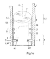
- Fig. 1a is a first embodiment of an inventive embodiment of a piston 1 with a spring loaded guide shoe 8, 81 shown in a schematic manner.
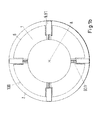
- Fig. 1b shows for better understanding the piston 1 of Fig. 1a in a section along the section line II.
- the piston 1 according to the invention Fig. 1 a or Fig. 1b is a piston 1 for a two-stroke large diesel engine with usually several cylinders 2.
- the piston 1 is shown in the installed state and is in a conventional manner along a cylinder axis A between a top dead center and a bottom dead center in the axial direction and arranged to move back and forth.
- a piston ring packing 3 comprising two piston rings 31, 32 is provided, which is arranged between a piston crown 4 with a top land 5 and a piston skirt 6.
- the piston skirt 6 forms a lower section of the piston 1 facing away from a combustion chamber surface 7 of the piston 1.
- a total of four centering means 8, 81 are provided for radial centering of the piston 1 in the cylinder 2 on the piston skirt 6 of the piston 1 provided in the form of loaded with a spring element 801 guide shoes 81 on the piston 1.
- the four guide shoes 81 ensure that the piston 1 is guided securely and cleanly centered in the cylinder 2 in all operating states of the large diesel engine, so that, for example, the antipolishing ring (not shown for reasons of clarity) can optimally remove all deposits from the piston crown 4 without the piston 1 in its movement with the Antipolihing ring or the cylinder wall may come into contact, although the annular gap between the piston 1 and the cylinder wall is chosen to be much smaller than is absolutely necessary when using known piston. It goes without saying that, for example, less than four, possibly only three guide shoes or even more than four guide shoes can be provided.
- FIG. 2 is a cross section through a piston 1 according to a second embodiment of the present invention shown schematically, wherein the centering means 8 here is a loaded with a guide spring 802 guide ring 82.
- the guide ring 82 is designed such that an outer diameter is only slightly smaller than the inner diameter of the cylinder 2.
- the piston 1 is then kept centered with respect to the guide ring 82. That is the decisive difference to a piston ring 31, 32.
- the Kolbering 31, 32 is free floating in one Supported piston ring groove, which has the consequence that the piston ring 31, 32 is basically not able to center the piston 1 in the cylinder 2, which is accomplished by the guide spring 802 when using the guide ring 82.
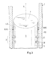
- Fig. 3 shows a third specific embodiment with a centering means 8, 83 in the form of a fixed, not loaded with a spring or pneumatically or hydraulically loaded guide shoe 83, which is arranged here for example on the piston crown 4.
- the fixed guide shoes of which, for example, three can be distributed at the same distance over the circumference of the piston 1, are designed such that their radial extent is selected so that the guide shoes 83 all slide simultaneously on the cylinder wall and so keep the piston 1 centered ,
- the surfaces of the guide shoes 83 that come into contact with the cylinder wall are selected to be so small and designed such that the cylinder wall or the lubricating oil film on the cylinder wall is not adversely affected by the guide shoes 83.
- Fig. 4 shows a fourth embodiment with a guide belt 84 with guide ribs 804, wherein the guide belt 84 is configured such that only the very narrow guide ribs 804, which are provided in the present example helically in the guide band 84, contact the cylinder wall and so the piston 1 in the cylinder 2 safely centering lead.
- the surfaces of the guide webs 804 that come into contact with the cylinder wall of the cylinder 2 are selected to be so small and designed such that the cylinder wall or the lubricating oil film on the cylinder wall is not adversely affected by the guide webs 804.
- a fifth embodiment of the present invention is shown schematically, in which in radial Direction elastically acting guide surfaces 85 are provided on the piston skirt 6, which extend away from the piston skirt 6 in the axial direction wherein a plurality of guide surfaces 85, preferably two, three, four or five guide surfaces 85 arranged at a predetermined distance from each other with respect to a circumferential direction on the piston 1 could be.
- An outer diameter of the piston 1 in the region of the guide surfaces 85 is chosen only slightly larger than the inner diameter of the cylinder 2. The fact that the guide surfaces 85 are configured elastically in the radial direction, the piston 1 is always guided over the guide surfaces 85 in a centered position in the cylinder 2.
- the surfaces of the guide surfaces 85 that come into contact with the cylinder wall of the cylinder 2 and the magnitude of the radially acting forces on the cylinder wall through the guide surfaces 85 are selected and designed such that the cylinder wall or lubricating oil film on the cylinder wall passes through the guide surfaces 85 not be adversely affected.
- the present invention it is possible for the first time by the present invention to massively reduce the gap between the piston and the cylinder wall or between the piston and anti-polishing, so that a significantly improved effect of the anti-polishing ring is ensured. And without the risk that when, for example when changing the operating condition of the engine towards a higher load or a higher speed of the outer piston diameter larger than the inner diameter of the cylinder or the anti-polishing ring, the piston jammed in the cylinder or the piston crown comes into contact with the antipolishing ring, which is reliably prevented by the use of the piston according to the invention.
Landscapes
- Engineering & Computer Science (AREA)
- Chemical & Material Sciences (AREA)
- Combustion & Propulsion (AREA)
- Mechanical Engineering (AREA)
- General Engineering & Computer Science (AREA)
- Pistons, Piston Rings, And Cylinders (AREA)
Priority Applications (1)
| Application Number | Priority Date | Filing Date | Title |
|---|---|---|---|
| EP11189399A EP2479413A1 (de) | 2011-01-24 | 2011-11-16 | Kolben für eine Hubkolbenbrennkraftmaschine |
Applications Claiming Priority (2)
| Application Number | Priority Date | Filing Date | Title |
|---|---|---|---|
| EP11151883 | 2011-01-24 | ||
| EP11189399A EP2479413A1 (de) | 2011-01-24 | 2011-11-16 | Kolben für eine Hubkolbenbrennkraftmaschine |
Publications (1)
| Publication Number | Publication Date |
|---|---|
| EP2479413A1 true EP2479413A1 (de) | 2012-07-25 |
Family
ID=44146795
Family Applications (1)
| Application Number | Title | Priority Date | Filing Date |
|---|---|---|---|
| EP11189399A Withdrawn EP2479413A1 (de) | 2011-01-24 | 2011-11-16 | Kolben für eine Hubkolbenbrennkraftmaschine |
Country Status (4)
| Country | Link |
|---|---|
| EP (1) | EP2479413A1 (ja) |
| JP (1) | JP6130100B2 (ja) |
| KR (1) | KR101941285B1 (ja) |
| CN (1) | CN102606338B (ja) |
Families Citing this family (2)
| Publication number | Priority date | Publication date | Assignee | Title |
|---|---|---|---|---|
| DE102016007727A1 (de) * | 2016-06-23 | 2017-12-28 | Man Truck & Bus Ag | Brennkraftmaschine, insbesondere Hubkolben-Brennkraftmaschine |
| CN110722206A (zh) * | 2019-11-25 | 2020-01-24 | 汉中市智海精密机械工具有限责任公司 | 一种自定心拉刀前导结构 |
Citations (8)
| Publication number | Priority date | Publication date | Assignee | Title |
|---|---|---|---|---|
| FR528814A (fr) * | 1920-03-24 | 1921-11-19 | Harry Ralph Ricardo | Perfectionnements apportés aux pistons |
| US1654595A (en) * | 1926-07-22 | 1928-01-03 | John A Cornell | Means for centralizing pistons |
| GB377374A (en) * | 1931-06-10 | 1932-07-28 | C M I Engineering Company Ltd | An improved aluminium alloy piston for internal combustion engines |
| US2300647A (en) * | 1940-01-15 | 1942-11-03 | Vacuum Air Pressure Company Lt | Piston |
| US2712483A (en) * | 1953-05-15 | 1955-07-05 | Patrick J Ciaccia | Friction-reducing piston construction for internal combustion engines |
| JPS5399407U (ja) * | 1977-01-18 | 1978-08-11 | ||
| US4268042A (en) * | 1980-05-08 | 1981-05-19 | Borlan Albert G | Flexible bellows piston seal |
| US20040149125A1 (en) * | 2003-01-31 | 2004-08-05 | Tetra Laval Holdings & Finance, S.A. | Fill pump piston centering support |
Family Cites Families (13)
| Publication number | Priority date | Publication date | Assignee | Title |
|---|---|---|---|---|
| US2438243A (en) * | 1944-10-20 | 1948-03-23 | Stanley M Zoromskis | Internal-combustion engine piston |
| JPS5633573B2 (ja) * | 1973-06-04 | 1981-08-04 | ||
| JPS5832149U (ja) * | 1981-08-26 | 1983-03-02 | 本田技研工業株式会社 | ピストンの振れ止め装置 |
| JPS5892438U (ja) * | 1981-12-17 | 1983-06-22 | トヨタ自動車株式会社 | 内燃機関用ピストンの摩擦低減装置 |
| JPS61120062U (ja) * | 1985-01-17 | 1986-07-29 | ||
| JPS636268A (ja) * | 1986-06-26 | 1988-01-12 | Toyota Autom Loom Works Ltd | エンジン用ピストン |
| GB2283555A (en) * | 1993-11-04 | 1995-05-10 | Ford Motor Co | Piston ring seal |
| JPH09317553A (ja) * | 1996-05-27 | 1997-12-09 | Nippon Soken Inc | 内燃機関用ピストン |
| DE19723047A1 (de) * | 1997-06-02 | 1998-12-03 | Georg Weber | Abmessung der Ringnut für Kolbenringe in Verbrennungsmaschinen (z. B. Ottomotoren) |
| JP4661831B2 (ja) * | 2007-06-15 | 2011-03-30 | トヨタ自動車株式会社 | ピストン及び内燃機関 |
| JP2009264143A (ja) * | 2008-04-22 | 2009-11-12 | Mitsubishi Heavy Ind Ltd | ディーゼル機関、及びピストン |
| EP2175107A1 (de) * | 2008-10-08 | 2010-04-14 | Wärtsilä Schweiz AG | Verfahren zum Schmieren eines Grossdieselmotors sowie Grossdieselmotor |
| EP2243940A1 (de) * | 2009-04-06 | 2010-10-27 | Wärtsilä Schweiz AG | Reduziereinrichtung zur Reduzierung eines Gasdrucks auf ein Kolbenringpaket einer Hubkolbenbrennkraftmaschine |
-
2011
- 2011-11-16 EP EP11189399A patent/EP2479413A1/de not_active Withdrawn
- 2011-12-06 KR KR1020110129656A patent/KR101941285B1/ko active Active
- 2011-12-13 CN CN201110415206.7A patent/CN102606338B/zh active Active
-
2012
- 2012-01-23 JP JP2012011303A patent/JP6130100B2/ja active Active
Patent Citations (8)
| Publication number | Priority date | Publication date | Assignee | Title |
|---|---|---|---|---|
| FR528814A (fr) * | 1920-03-24 | 1921-11-19 | Harry Ralph Ricardo | Perfectionnements apportés aux pistons |
| US1654595A (en) * | 1926-07-22 | 1928-01-03 | John A Cornell | Means for centralizing pistons |
| GB377374A (en) * | 1931-06-10 | 1932-07-28 | C M I Engineering Company Ltd | An improved aluminium alloy piston for internal combustion engines |
| US2300647A (en) * | 1940-01-15 | 1942-11-03 | Vacuum Air Pressure Company Lt | Piston |
| US2712483A (en) * | 1953-05-15 | 1955-07-05 | Patrick J Ciaccia | Friction-reducing piston construction for internal combustion engines |
| JPS5399407U (ja) * | 1977-01-18 | 1978-08-11 | ||
| US4268042A (en) * | 1980-05-08 | 1981-05-19 | Borlan Albert G | Flexible bellows piston seal |
| US20040149125A1 (en) * | 2003-01-31 | 2004-08-05 | Tetra Laval Holdings & Finance, S.A. | Fill pump piston centering support |
Also Published As
| Publication number | Publication date |
|---|---|
| KR101941285B1 (ko) | 2019-01-22 |
| CN102606338B (zh) | 2015-12-09 |
| JP2012154331A (ja) | 2012-08-16 |
| JP6130100B2 (ja) | 2017-05-17 |
| KR20120085642A (ko) | 2012-08-01 |
| CN102606338A (zh) | 2012-07-25 |
Similar Documents
| Publication | Publication Date | Title |
|---|---|---|
| EP1936245B1 (de) | Kolben mit einem Ölsammelring | |
| EP2505880B2 (de) | Ölabstreifring | |
| DE102010020491B4 (de) | Verfahren zum Betrieb einer Hubkolbenbrennkraftmaschine und Kolben für eine Hubkolbenbrennkraftmaschine | |
| EP2243940A1 (de) | Reduziereinrichtung zur Reduzierung eines Gasdrucks auf ein Kolbenringpaket einer Hubkolbenbrennkraftmaschine | |
| EP2551503A1 (de) | Kolben, Kolbenring und Ölverteilring für eine Hubkolbenbrennkraftmaschine | |
| DE69311142T2 (de) | KOLBENOBERRING FüR BRENNKRAFTMASCHINEN | |
| DE69601375T2 (de) | Brennkraftmaschine mit einem koksschabring in einem zylinder | |
| EP2672082A1 (de) | Schmiermittelsammelvorrichtung | |
| EP2199549A1 (de) | Zylinderschmiervorrichtung, sowie eine Hubkolbenbrennkraftmaschine mit einer Zylinderschmiervorrichtung | |
| EP2503116A1 (de) | Zylinderanordnung, sowie Kolben für eine längsgespülte Hubkolbenbrennkraftmaschine | |
| EP2236800A1 (de) | Zylinder mit Mitteln zur Verteilung von Schmiermittel | |
| EP2602453A1 (de) | Kolben und Zylinderanordnung für eine Hubkolbenbrennkraftmaschine, sowie Verfahren zur Entfernung einer Ablagerung von einem Kolben | |
| DE102010020490B4 (de) | Verfahren zur Optimierung der Funktion eines Kolbenringpakets sowie hierfür geeignetes Kolbenringpaket | |
| EP2551504A1 (de) | Kolben und Ölverteilring für eine Hubkolbenbrennkraftmaschine | |
| EP3636967B1 (de) | Ölabstreifring für eine kolbenstange | |
| DE102008028052A1 (de) | Verfahren zur Stabilisierung eines Kolbenrings und Mittel zur Durchführung dieses Verfahrens | |
| WO2017207172A1 (de) | Zweiteiliger ölabstreifring mit öldruckeffektstegen | |
| EP2954164A1 (de) | Rotationskolbenmotor | |
| DE102013002744B4 (de) | System zur Beeinflussung der Gleiteigenschaften einer Gleitpaarung | |
| EP2620607A1 (de) | Kolben-Zylinder-Einheit und Verfahren zur Schmiermittelversorgung eines Kolbens einer Kolben-Zylinder-Einheit für eine Hubkolbenbrennkraftmaschine | |
| EP3049696B1 (de) | Kolben mit kolbenringnut, insbesondere kompressionsnut | |
| EP2664754A1 (de) | Verfahren und Zylinderschmiereinrichtung zur Schmierung einer Kolben-Zylinder-Einheit einer Hubkolbenbrennkraftmaschine | |
| EP3510305A1 (de) | Zweiteiliger ölabstreifring mit axialer stabilisierung und twistausgleich | |
| AT522701B1 (de) | Kolben | |
| DE3511837C1 (de) | Hubkolbenbrennkraftmaschine |
Legal Events
| Date | Code | Title | Description |
|---|---|---|---|
| PUAI | Public reference made under article 153(3) epc to a published international application that has entered the european phase |
Free format text: ORIGINAL CODE: 0009012 |
|
| AK | Designated contracting states |
Kind code of ref document: A1 Designated state(s): AL AT BE BG CH CY CZ DE DK EE ES FI FR GB GR HR HU IE IS IT LI LT LU LV MC MK MT NL NO PL PT RO RS SE SI SK SM TR |
|
| AX | Request for extension of the european patent |
Extension state: BA ME |
|
| 17P | Request for examination filed |
Effective date: 20130125 |
|
| 17Q | First examination report despatched |
Effective date: 20160212 |
|
| STAA | Information on the status of an ep patent application or granted ep patent |
Free format text: STATUS: EXAMINATION IS IN PROGRESS |
|
| STAA | Information on the status of an ep patent application or granted ep patent |
Free format text: STATUS: THE APPLICATION IS DEEMED TO BE WITHDRAWN |
|
| 18D | Application deemed to be withdrawn |
Effective date: 20190131 |