EP2479482A2 - Schwimmbeckenbeleuchtungsanordnung - Google Patents
Schwimmbeckenbeleuchtungsanordnung Download PDFInfo
- Publication number
- EP2479482A2 EP2479482A2 EP11168302A EP11168302A EP2479482A2 EP 2479482 A2 EP2479482 A2 EP 2479482A2 EP 11168302 A EP11168302 A EP 11168302A EP 11168302 A EP11168302 A EP 11168302A EP 2479482 A2 EP2479482 A2 EP 2479482A2
- Authority
- EP
- European Patent Office
- Prior art keywords
- pool
- assembly
- light
- water
- set forth
- Prior art date
- Legal status (The legal status is an assumption and is not a legal conclusion. Google has not performed a legal analysis and makes no representation as to the accuracy of the status listed.)
- Ceased
Links
Images




Classifications
-
- F—MECHANICAL ENGINEERING; LIGHTING; HEATING; WEAPONS; BLASTING
- F21—LIGHTING
- F21S—NON-PORTABLE LIGHTING DEVICES; SYSTEMS THEREOF; VEHICLE LIGHTING DEVICES SPECIALLY ADAPTED FOR VEHICLE EXTERIORS
- F21S8/00—Lighting devices intended for fixed installation
- F21S8/03—Lighting devices intended for fixed installation of surface-mounted type
- F21S8/033—Lighting devices intended for fixed installation of surface-mounted type the surface being a wall or like vertical structure, e.g. building facade
-
- F—MECHANICAL ENGINEERING; LIGHTING; HEATING; WEAPONS; BLASTING
- F21—LIGHTING
- F21V—FUNCTIONAL FEATURES OR DETAILS OF LIGHTING DEVICES OR SYSTEMS THEREOF; STRUCTURAL COMBINATIONS OF LIGHTING DEVICES WITH OTHER ARTICLES, NOT OTHERWISE PROVIDED FOR
- F21V29/00—Protecting lighting devices from thermal damage; Cooling or heating arrangements specially adapted for lighting devices or systems
- F21V29/50—Cooling arrangements
- F21V29/70—Cooling arrangements characterised by passive heat-dissipating elements, e.g. heat-sinks
- F21V29/74—Cooling arrangements characterised by passive heat-dissipating elements, e.g. heat-sinks with fins or blades
-
- F—MECHANICAL ENGINEERING; LIGHTING; HEATING; WEAPONS; BLASTING
- F21—LIGHTING
- F21V—FUNCTIONAL FEATURES OR DETAILS OF LIGHTING DEVICES OR SYSTEMS THEREOF; STRUCTURAL COMBINATIONS OF LIGHTING DEVICES WITH OTHER ARTICLES, NOT OTHERWISE PROVIDED FOR
- F21V29/00—Protecting lighting devices from thermal damage; Cooling or heating arrangements specially adapted for lighting devices or systems
- F21V29/50—Cooling arrangements
- F21V29/70—Cooling arrangements characterised by passive heat-dissipating elements, e.g. heat-sinks
- F21V29/83—Cooling arrangements characterised by passive heat-dissipating elements, e.g. heat-sinks the elements having apertures, ducts or channels, e.g. heat radiation holes
-
- B—PERFORMING OPERATIONS; TRANSPORTING
- B05—SPRAYING OR ATOMISING IN GENERAL; APPLYING FLUENT MATERIALS TO SURFACES, IN GENERAL
- B05B—SPRAYING APPARATUS; ATOMISING APPARATUS; NOZZLES
- B05B1/00—Nozzles, spray heads or other outlets, with or without auxiliary devices such as valves, heating means
- B05B1/02—Nozzles, spray heads or other outlets, with or without auxiliary devices such as valves, heating means designed to produce a jet, spray, or other discharge of particular shape or nature, e.g. in single drops, or having an outlet of particular shape
- B05B1/04—Nozzles, spray heads or other outlets, with or without auxiliary devices such as valves, heating means designed to produce a jet, spray, or other discharge of particular shape or nature, e.g. in single drops, or having an outlet of particular shape in flat form, e.g. fan-like, sheet-like
- B05B1/046—Outlets formed, e.g. cut, in the circumference of tubular or spherical elements
-
- B—PERFORMING OPERATIONS; TRANSPORTING
- B05—SPRAYING OR ATOMISING IN GENERAL; APPLYING FLUENT MATERIALS TO SURFACES, IN GENERAL
- B05B—SPRAYING APPARATUS; ATOMISING APPARATUS; NOZZLES
- B05B1/00—Nozzles, spray heads or other outlets, with or without auxiliary devices such as valves, heating means
- B05B1/26—Nozzles, spray heads or other outlets, with or without auxiliary devices such as valves, heating means with means for mechanically breaking-up or deflecting the jet after discharge, e.g. with fixed deflectors; Breaking-up the discharged liquid or other fluent material by impinging jets
- B05B1/262—Nozzles, spray heads or other outlets, with or without auxiliary devices such as valves, heating means with means for mechanically breaking-up or deflecting the jet after discharge, e.g. with fixed deflectors; Breaking-up the discharged liquid or other fluent material by impinging jets with fixed deflectors
- B05B1/267—Nozzles, spray heads or other outlets, with or without auxiliary devices such as valves, heating means with means for mechanically breaking-up or deflecting the jet after discharge, e.g. with fixed deflectors; Breaking-up the discharged liquid or other fluent material by impinging jets with fixed deflectors the liquid or other fluent material being deflected in determined directions
-
- B—PERFORMING OPERATIONS; TRANSPORTING
- B05—SPRAYING OR ATOMISING IN GENERAL; APPLYING FLUENT MATERIALS TO SURFACES, IN GENERAL
- B05B—SPRAYING APPARATUS; ATOMISING APPARATUS; NOZZLES
- B05B15/00—Details of spraying plant or spraying apparatus not otherwise provided for; Accessories
- B05B15/60—Arrangements for mounting, supporting or holding spraying apparatus
- B05B15/65—Mounting arrangements for fluid connection of the spraying apparatus or its outlets to flow conduits
- B05B15/652—Mounting arrangements for fluid connection of the spraying apparatus or its outlets to flow conduits whereby the jet can be oriented
-
- F—MECHANICAL ENGINEERING; LIGHTING; HEATING; WEAPONS; BLASTING
- F21—LIGHTING
- F21W—INDEXING SCHEME ASSOCIATED WITH SUBCLASSES F21K, F21L, F21S and F21V, RELATING TO USES OR APPLICATIONS OF LIGHTING DEVICES OR SYSTEMS
- F21W2131/00—Use or application of lighting devices or systems not provided for in codes F21W2102/00-F21W2121/00
- F21W2131/40—Lighting for industrial, commercial, recreational or military use
- F21W2131/401—Lighting for industrial, commercial, recreational or military use for swimming pools
-
- F—MECHANICAL ENGINEERING; LIGHTING; HEATING; WEAPONS; BLASTING
- F21—LIGHTING
- F21Y—INDEXING SCHEME ASSOCIATED WITH SUBCLASSES F21K, F21L, F21S and F21V, RELATING TO THE FORM OR THE KIND OF THE LIGHT SOURCES OR OF THE COLOUR OF THE LIGHT EMITTED
- F21Y2103/00—Elongate light sources, e.g. fluorescent tubes
- F21Y2103/30—Elongate light sources, e.g. fluorescent tubes curved
- F21Y2103/33—Elongate light sources, e.g. fluorescent tubes curved annular
-
- F—MECHANICAL ENGINEERING; LIGHTING; HEATING; WEAPONS; BLASTING
- F21—LIGHTING
- F21Y—INDEXING SCHEME ASSOCIATED WITH SUBCLASSES F21K, F21L, F21S and F21V, RELATING TO THE FORM OR THE KIND OF THE LIGHT SOURCES OR OF THE COLOUR OF THE LIGHT EMITTED
- F21Y2113/00—Combination of light sources
- F21Y2113/10—Combination of light sources of different colours
- F21Y2113/13—Combination of light sources of different colours comprising an assembly of point-like light sources
-
- F—MECHANICAL ENGINEERING; LIGHTING; HEATING; WEAPONS; BLASTING
- F21—LIGHTING
- F21Y—INDEXING SCHEME ASSOCIATED WITH SUBCLASSES F21K, F21L, F21S and F21V, RELATING TO THE FORM OR THE KIND OF THE LIGHT SOURCES OR OF THE COLOUR OF THE LIGHT EMITTED
- F21Y2115/00—Light-generating elements of semiconductor light sources
- F21Y2115/10—Light-emitting diodes [LED]
Definitions
- This invention relates generally to the field of pool equipment, either above or in-ground pools. More particularly, this invention relates to pool fixtures designed for adapting a pool light assembly to a pool. Most particularly, this invention relates to the field of such devices, which offer pool illumination plus cooling of the illumination device and surrounding structure.
- pool lighting has become more and more popular. While pool lighting has been around for many years, the issues associated with such lighting have not been fully appreciated. For example, some illumination devices, especially in the beginning, used lighting elements that would get extremely hot and cause rapid deterioration of the entire lighting assembly. Such heat would lead to increased maintenance by the pool owner and constant replacing of not only the light assembly unit, but also the entire inlet housing. Sometimes a pool would need to be drained just to do the necessary maintenance.
- pool lighting has become increasingly popular. Initially pool lighting was used strictly for safety purposes. Nighttime swimming, although not notably popular, was done with much greater safety at night with lighted pools for obvious reasons.
- color lighting has frequently been added to create nighttime pool water as a home's water feature. Such lighting provided viewers with greater interest and had the same or greater benefits to peaceful and tranquil viewing. Additional enhancements such as sequential color lighting have also been added.
- What is needed is a structure for allowing a pool lighting installation to be cooled without resorting to undue structure or expensive maintenance.
- the ideal structure would conform in general physical appearance and dimensions of existing pool water inlets or returns, while providing cooling to the needed structure of the illumination structure.
- the structure of the improved pool light assembly with cooling structure in accordance with the present invention includes using the existing pool inlet or return with a few structural modifications. These structural modifications include providing a housing inlet having a first portion on the dry side of the pool wall and a second portion immersed in the pool water.
- the second portion includes a flange exterior and the interior defining a base. One or more openings on the flange allow pool water into the base.
- the housing is secured to the pool water by means well known in the art.
- the base is provided with a series of ridges, which encourage pool water circulation through the base. Sealing and retaining members separate the water from the electrical elements and retaining the unit together in working order. This way pool water is used to circulate around the light assembly in close proximity to the lighting elements. Using this structure, the cooling of the light assembly occurs without undue modifications to the existing pool and lighting structures.
- It is an object of this invention is to provide a pool light assembly, which uses pool water to cool the assembly.
- the pool light assembly in accordance with this invention, comprises:
- the light assembly interior base includes a series of radially extending ribs, which are separated by opposed dividers. This pattern has been found to facilitate the flow of pool water in the proximity to the light sub-assembly and in so doing adds to the cooling effect of the structure.
- the light assembly includes the light assembly includes a reflector plate as part of the retaining ring.
- the reflector plate reflects light and facilitates a brighter and more intense lighting display.
- the reflector plate focuses and concentrates the light as desired and this can especially enhance a lighting pattern with multi-colored lights.
- the assembly includes a plurality of lighting elements; each of the lighting elements being positioned around the ring in a rotary extending pattern.
- the light elements are, in one embodiment unevenly spaced apart. In another embodiment the lights are of various colors. In these and other embodiments, the lighting elements are high intensity LED's.
- the pool return 100 includes a power supply head 110 and the pool light assembly in accordance with this invention, and generally denoted by the numeral 20.
- the pool return 100 includes a water inlet 102, which leads to a water channel 104.
- the pool light assembly 20 includes a water inlet housing 30.
- the housing 30 has a central opening 31 defining the water channel 104.
- the power supply head110 mates with the housing 30, as shown particularly clearly in Fig. 1 .
- the power supply head 110 has an electrical channel 112 and is shown in Fig. 1 with electrical wires 114 extending to an electrical source (not shown) such as an electrical outlet (also, not shown).
- the power supply head 110 distributes power to the light assembly 20 through electrical conduit shown clearly in Fig. 1 .
- the light assembly housing 30 has an exterior 32. As shown in Fig. 1 , the housing 30 is mounted on a pool wall 50. The housing 30 has a first portion 40 located on the dry side of the mounting and a second portion 42 immersed in pool water. In the embodiment shown in Fig. 1 two washers 33 on the pool side and a tightening nut 35 on the dry side form a water tight seal around the opening in the pool where the housing 20 is inserted.
- the second portion 42 of the housing 30 includes a flange member 36.
- the flange member 36 has an interior 34 as best seen in Fig. 2 - 4 .
- the interior 36 has a central opening 38 allowing water to pass therethrough and communicate with the water channel 104 through inlet 102.
- the interior 36 defines a base 39 for the light assembly 20.
- the flange member 36 sits, during operation, immersed in pool water. At least one notch 45 is provided in the exterior 32 of the flange member 36 extending into the interior 34. Thus, constructed, the notch 45 that allows pool water to communicate freely between the interior 34 and exterior 32 and throughout the flange member base 39.
- the interior 36 includes a raised pattern of ribs 60 and dividers 62.
- the ribs 60 and dividers 62 can, of course, be made to have any particular pattern within the spirit and scope of the invention.
- the pattern may well be non-symmetrical or zigzagged within the spirit and scope of the invention herein.
- the functional requirement for such a pattern is to ensure that water flows freely through the base 39 to provide a cooling effect for the light sub-assembly as described below.
- the light assembly in accordance with this invention includes both an electrical channel and a water channel. This is particularly well described with respect to Applicant's earlier related invention and incorporated herein and referred to here as if set forth in full and incorporated herein for all purposes consistent with full disclosure and establishment of an antecedent basis.
- a nozzle 70 fits over the water channel 104.
- such a nozzle defines an eyeball nozzle and can be useful in directing a limited amount of water flow in the pool. More recent developments in pool technology include Applicants' invention of vented directional nozzle as shown particularly with reference to Figs. 10 and 11 .
- the eyeball nozzle can either be replaced by such a directional nozzle or used in conjunction therewith as will be described below with reference to Figs. 10 and 11 .
- the base has two notches 45. It will be appreciated that only one such notch is required. However, two notches have been found to facilitate the flow of water through the base 39, which, of course, aids in the cooling of the light assembly. While, more notches are within the spirit and scope of the invention, such have not been found to greatly aid the cooling effect of pool water through the base and therefore, the best mode of carrying out the invention has to date been found by using the two notch embodiment illustrated by the drawing herein.
- a sealing plate 80 covers and seals the base 39 when the light assembly is fully assembly as will be more fully appreciated below.
- the sealing plate 80 has a central opening 82 for allowing pool water to enter the water channel 104 and for maintaining open communication with pool water and the pool return 100.
- the central opening 82 is also sized and shaped for compatible overlay with the nozzle 70 as also clearly shown in Fig. 2 .
- the central opening 82 is large enough to allow some slight rotation movement of the nozzle 70 while providing a snug fit to discourage water leak paths through the base and into the other elements of the light assembly 20.
- the sealing plate 80 includes in the embodiment shown an electrical plug-in connection member 84.
- the member 84 is sized and shaped for compatible and mating connection with the electrical channel 112 and the plug-in connector therein.
- the member 84 fills the electrical channel 112 and the wiring 114 connects with the member allowing electrical connection there between.
- a light sub-assembly 90 fits within the outer periphery of the sealing member 80.
- the light sub-assembly 90 includes a plurality of lighting elements 92 on a circuit board 94 in the shape of ring.
- the circuit board 94 includes a plug-in connector 96. As shown, the plug-in connector is sized and shaped for a mating force fit with the electrical wiring as shown.
- the lighting elements 92 obtain electrical power for the electrical power head 110 through the wiring 112 when the plug-in connector 96 is plugged in also as illustrated in Fig. 2 .
- halogen lighting elements have become frowned upon because while they generate adequate light, they do so at a high energy costs. Lighting elements such as high intensity LED's are preferred in most situations. However, both types of lighting elements as well as others are within the spirit and scope of this invention.
- a retaining member 91 is designed to snap fit over the light sub-assembly 90.
- the light sub-assembly 90 includes posts 93 and the retaining member has female projections 95, which create a secure snap, fit there between.
- the retaining member 91 has a central opening 97 for allow water to pass therethrough to the water channel 104.
- the lighting elements regardless of type, typically project from the light sub-assembly 90. Therefore, the retaining member 91 has a series of matching opening for allowing the lighting elements 92 to pass therethrough. Once assembled the retaining member 91 snap fits to the light sub-assembly 90 providing a secure assembly for the entire light assembly 20.
- a lens cover 140 is provided to cover retaining member 91. Similarly, the lens cover 140 has a central opening 142 allowing communication of the pool water into the water channel 104.
- the lens cover 140 has periphery with a groove and as is known in the art snap fits into the outer periphery of the retaining member 91. The fit is secure to discourage any water from entering into the light assembly 20 except, of course, through the central opening 142.
- the retaining member 91 in a preferred embodiment includes a reflective surface 99 surrounding the projecting lighting elements 92.
- the retaining member 91 thereby defines a reflector plate.
- Such a reflector plate is particular useful and desirable when colored lighting elements are used.
- the lighting elements may be of different colors by adapter different lighting element covers over the LEDS.
- the lens cover 140 may be of different colors, having different color segments and shapes to provide more enhanced pool lighting.
- the water channel 104 extends through the body of light assembly 20.
- the central openings in each of the above elements are aligned so as to create a single water channel 104.
- Figs. 3 and 4 there is shown the housing 30 outside of the pool wall 50.
- the flange 36 has an external screw exterior with an open channel for communicating with the water channel 104.
- the housing With the additional of the washers 33 on the pool side of the pool wall 50, the housing is secured for leak proof connection. This is especially important on thin walled above ground pools. It is critical to create a connection that will not compromise the pool wall while providing a connection that also seals and prevents water leakage to the dry side of the pool.
- the housing 30 is adapted to provide the power supply head 110 a location for easy and convenient plug-in connection.
- the housing 30 includes a flat surface 130 have head opening 132 which match and mate with the male connectors of the power supply head 110. Additionally, the flat surface 130 is provided with a locking member 134, which securely connects the power supply head 110 to the housing 30.
- a water pump for filtering pool water is provided.
- the pump pumps water through the water channel of the light assembly and through the various central openings of the elements as described with respect to Figs. 1 through 4 .
- water both fresh and pool flow through the light assembly and into the pool and are returned, water enters and exits through the notches 45 and swirls about the base 39 in close proximity to the light sub-assembly 90 and lighting elements 92as described above.
- Fresh water flows through the water channel 104 and pool water through the return and into the pool.
- the source of the intense heat in the light assembly 20 are the lighting elements 92.
- the heat from these lighting elements 92 can be quite extreme.
- this must been without compromising the electrical integrity of the light assembly 20 as a whole and without resorting to structures and devices which will not work within conventional structure already established in the art.
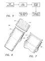
- FIG. 6 & 7 there is shown a novel concept for an advanced water channel return.
- the water channel 104 feeds into a filter and a fresh water source.
- Applicants herein provide the housing 30 with dry side screw threads 137 for such connection.
- the novel concept includes an adapter 200 at the end of the water channel 204, which is provided with screw threads 202.
- the threads 202 mate compatibly with housing threads 137.
- the adapter 200 includes a seat 208, sized and shaped for compatible compression fit with the compression ring 206.
- the eye-ball nozzle 70 in accordance with the instant invention.
- the nozzle 70 has a central opening consistent with allowing water to enter the water channel as described above.
- the central opening includes internal screw threads 72.
- the novel aspects of providing a directional nozzle are facilitated by such threads 72.
- the oblong and symmetrical shape of the nozzle 70 provide greater durability and reliability as well as providing the nozzle 70 with a degree of rotate. The shape results in more functionality over a simple round or spherical nozzle.
- the vented directional nozzle 170 includes a main body 172 and a directional head end 174.
- the main body 172 has a series of vents 176. These vents 176 allow pool water to pass through without disturbing the flow to a great degree.
- the head end 174 is partially closed and includes a hood, which deflects water at a right angle to the main body 172.
- the head end is rotated to the desired position to direct pool flow.
- the main body has an end 178 opposite the head end 174.
- the end 178 screws into the nozzle 70 of Figs. 8 & 9 , using the threaded end.
- the vents 176 being present, over rotation of the directional nozzle 170 into the nozzle 70 does not result in breakable.
- the directional nozzle 170 simply bends or gives and no harm is done to either nozzle 70 or 170.
- the directional nozzle 170 is screwed in the nozzle 70 until tightened and then backed off to provide the directional flow of pool desired.
- the nozzle 170 is adaptable to the novel light assembly in accordance with this invention.
Landscapes
- Engineering & Computer Science (AREA)
- General Engineering & Computer Science (AREA)
- Architecture (AREA)
- Arrangement Of Elements, Cooling, Sealing, Or The Like Of Lighting Devices (AREA)
- Non-Portable Lighting Devices Or Systems Thereof (AREA)
Applications Claiming Priority (1)
| Application Number | Priority Date | Filing Date | Title |
|---|---|---|---|
| US13/013,459 US8668348B2 (en) | 2011-01-25 | 2011-01-25 | Pool light assembly with cooling structure |
Publications (2)
| Publication Number | Publication Date |
|---|---|
| EP2479482A2 true EP2479482A2 (de) | 2012-07-25 |
| EP2479482A3 EP2479482A3 (de) | 2013-07-31 |
Family
ID=44118084
Family Applications (1)
| Application Number | Title | Priority Date | Filing Date |
|---|---|---|---|
| EP11168302.5A Ceased EP2479482A3 (de) | 2011-01-25 | 2011-05-31 | Schwimmbeckenbeleuchtungsanordnung |
Country Status (3)
| Country | Link |
|---|---|
| US (1) | US8668348B2 (de) |
| EP (1) | EP2479482A3 (de) |
| CN (1) | CN102620183B (de) |
Cited By (1)
| Publication number | Priority date | Publication date | Assignee | Title |
|---|---|---|---|---|
| EP2543928B1 (de) * | 2011-07-02 | 2026-03-25 | Thunder Host Limited | Verbesserte schwimmbeckenbeleuchtungsanordnung |
Families Citing this family (2)
| Publication number | Priority date | Publication date | Assignee | Title |
|---|---|---|---|---|
| US20140293585A1 (en) * | 2013-04-02 | 2014-10-02 | Wing-tak Hui | Pool Light Assembly |
| US11602032B2 (en) | 2019-12-20 | 2023-03-07 | Kohler Co. | Systems and methods for lighted showering |
Family Cites Families (33)
| Publication number | Priority date | Publication date | Assignee | Title |
|---|---|---|---|---|
| US4520514A (en) | 1983-04-29 | 1985-06-04 | Jandy Industries | Fitting for a swimming pool return line |
| US4717078A (en) | 1984-08-20 | 1988-01-05 | Arp George F | Eyeball fitting for increasing flow of return water to swimming pool |
| US5122936A (en) * | 1991-05-13 | 1992-06-16 | Spa Electrics Pty. Ltd. | Swimming pool lighting |
| US5207499A (en) * | 1991-06-04 | 1993-05-04 | Kdi American Products, Inc. | Integral light and liquid circulation fitting |
| US5217292A (en) * | 1991-09-03 | 1993-06-08 | Hydrabaths, Inc. | Whirlpool bath suction assembly having replaceable tub light therein |
| US5881401A (en) | 1997-05-27 | 1999-03-16 | Saputo; John I | Turbo return fitting for a swimming pool |
| DE19747980A1 (de) * | 1997-10-30 | 1999-05-06 | Wts Kereskedelmi Es Szolgaltat | Beleuchtungskörper für Schwimmbäder und ähnliches |
| US6422730B1 (en) * | 2000-03-17 | 2002-07-23 | Super Vision International, Inc. | Fiber optic light source with two chamber cooling |
| JP3792142B2 (ja) * | 2001-06-29 | 2006-07-05 | 秀男 清水 | 照明付き噴流ノズル型浴槽 |
| US6578207B1 (en) | 2001-10-09 | 2003-06-17 | Eric L. Fratilla | Return jet fitting for pools and spas |
| US20030147238A1 (en) * | 2002-02-07 | 2003-08-07 | Allen David G. | Liquid driven generator for low power electrical components |
| US6702451B1 (en) * | 2002-03-12 | 2004-03-09 | Patrick David Daane | Swimming pool jet lighting |
| US7244037B2 (en) * | 2002-09-09 | 2007-07-17 | Nexxus Lighting, Inc. | Detachable pool light |
| DE10312866A1 (de) * | 2003-03-19 | 2004-09-30 | Hansgrohe Ag | Dusche |
| GB2413840B (en) * | 2004-05-07 | 2006-06-14 | Savage Marine Ltd | Underwater lighting |
| US20060002105A1 (en) * | 2004-07-02 | 2006-01-05 | B&S Plastics, Inc. Dba Waterway Plastics | LED-illuminated spa jet |
| US20060044785A1 (en) * | 2004-08-30 | 2006-03-02 | Feng-Nien Lee | Solar lamp available for outdoor use |
| EP1653255A3 (de) * | 2004-10-29 | 2006-06-21 | Pentair Water Pool and Spa, Inc. | Linse mit einstellbarem Strahl für Unterwasserlicht |
| US7427036B2 (en) * | 2005-01-25 | 2008-09-23 | Kasco Marine, Inc. | Illuminated floating fountain |
| US7384165B2 (en) * | 2005-07-05 | 2008-06-10 | Kevin Doyle | Water feature with an LED system |
| CN2835784Y (zh) * | 2005-07-27 | 2006-11-08 | 陈兆辉 | 一种水池用装饰灯 |
| US7815329B2 (en) * | 2006-10-25 | 2010-10-19 | Sundance Spas, Inc. | Waterfall unit |
| US20080277493A1 (en) * | 2007-05-11 | 2008-11-13 | Gooten Innolife Corporation | Fountain lamp |
| DE102007029080A1 (de) * | 2007-06-21 | 2008-12-24 | Oase Gmbh | Scheinwerfereinheit und Wasserspiel |
| DE202007012249U1 (de) * | 2007-08-31 | 2007-10-25 | Seliger, Roland | Flexible Quellsteinleuchte |
| GB0803251D0 (en) * | 2008-02-22 | 2008-04-02 | Burnham Douglas P | A generator |
| US8042962B2 (en) * | 2008-02-28 | 2011-10-25 | G-G Distribution And Development Co., Inc. | Lighted fittings for bathing installations |
| DE202008010023U1 (de) * | 2008-07-26 | 2008-12-24 | Oase Gmbh | Vorrichtung zur Erzeugung eines beleuchteten Wasserstrahls |
| FR2935170B1 (fr) * | 2008-08-20 | 2013-05-10 | Didier Vincent | Dispositif d'eclairage amovible pour piscine |
| CN201305188Y (zh) * | 2008-10-24 | 2009-09-09 | 宁波东川游泳池设备有限公司 | 一种用于游泳池的净化剂容器 |
| CN201375937Y (zh) * | 2009-03-27 | 2010-01-06 | 谢泳 | 一种带彩灯的喷水口 |
| CN201513791U (zh) * | 2009-07-06 | 2010-06-23 | 浙江琅盛光电科技股份有限公司 | 一种环形水下灯 |
| US8079726B1 (en) * | 2010-08-11 | 2011-12-20 | Heng Kang Slate Lo, Ltd. | Pool light assembly |
-
2011
- 2011-01-25 US US13/013,459 patent/US8668348B2/en active Active
- 2011-05-31 EP EP11168302.5A patent/EP2479482A3/de not_active Ceased
-
2012
- 2012-01-13 CN CN201210013122.5A patent/CN102620183B/zh active Active
Non-Patent Citations (1)
| Title |
|---|
| None |
Cited By (1)
| Publication number | Priority date | Publication date | Assignee | Title |
|---|---|---|---|---|
| EP2543928B1 (de) * | 2011-07-02 | 2026-03-25 | Thunder Host Limited | Verbesserte schwimmbeckenbeleuchtungsanordnung |
Also Published As
| Publication number | Publication date |
|---|---|
| EP2479482A3 (de) | 2013-07-31 |
| US20120188748A1 (en) | 2012-07-26 |
| CN102620183B (zh) | 2016-01-20 |
| US8668348B2 (en) | 2014-03-11 |
| CN102620183A (zh) | 2012-08-01 |
Similar Documents
| Publication | Publication Date | Title |
|---|---|---|
| USRE50394E1 (en) | Light fixture with tiltable sealed light source | |
| US6241361B1 (en) | Submersible light fixture | |
| US7553040B2 (en) | Underwater pool light | |
| US20090264041A1 (en) | Serially controllable led lighting systems | |
| US7740367B2 (en) | Detachable pool light | |
| US5122936A (en) | Swimming pool lighting | |
| US7244037B2 (en) | Detachable pool light | |
| US7125146B2 (en) | Underwater LED light | |
| US5045978A (en) | Underwater lighting fixture | |
| US11209149B2 (en) | Emergency exit light | |
| EP2420725B1 (de) | Schwimmbeckenbeleuchtungsanordnung | |
| US20120106149A1 (en) | Underwater and landscape lighting system | |
| US7188378B2 (en) | Swimming pool immersed light fixture | |
| US11994282B2 (en) | Universal submersible LED lamp fixture/luminaire | |
| US8668348B2 (en) | Pool light assembly with cooling structure | |
| US8430521B2 (en) | Pool lighting assembly | |
| US9732955B2 (en) | Pool light assembly with cooling structure | |
| US8939598B1 (en) | Landscape light fixture with slide and lock mounting bracket assembly | |
| US20020030991A1 (en) | Swivel nightlight | |
| US20140293585A1 (en) | Pool Light Assembly | |
| WO2003025629A2 (en) | Fiber optic light system |
Legal Events
| Date | Code | Title | Description |
|---|---|---|---|
| PUAI | Public reference made under article 153(3) epc to a published international application that has entered the european phase |
Free format text: ORIGINAL CODE: 0009012 |
|
| AK | Designated contracting states |
Kind code of ref document: A2 Designated state(s): AL AT BE BG CH CY CZ DE DK EE ES FI FR GB GR HR HU IE IS IT LI LT LU LV MC MK MT NL NO PL PT RO RS SE SI SK SM TR |
|
| AX | Request for extension of the european patent |
Extension state: BA ME |
|
| PUAL | Search report despatched |
Free format text: ORIGINAL CODE: 0009013 |
|
| AK | Designated contracting states |
Kind code of ref document: A3 Designated state(s): AL AT BE BG CH CY CZ DE DK EE ES FI FR GB GR HR HU IE IS IT LI LT LU LV MC MK MT NL NO PL PT RO RS SE SI SK SM TR |
|
| AX | Request for extension of the european patent |
Extension state: BA ME |
|
| RIC1 | Information provided on ipc code assigned before grant |
Ipc: F21W 131/401 20060101ALI20130624BHEP Ipc: F21Y 101/02 20060101ALN20130624BHEP Ipc: F21S 8/00 20060101AFI20130624BHEP Ipc: F21V 29/00 20060101ALI20130624BHEP |
|
| 17P | Request for examination filed |
Effective date: 20140131 |
|
| RBV | Designated contracting states (corrected) |
Designated state(s): AL AT BE BG CH CY CZ DE DK EE ES FI FR GB GR HR HU IE IS IT LI LT LU LV MC MK MT NL NO PL PT RO RS SE SI SK SM TR |
|
| 17Q | First examination report despatched |
Effective date: 20140305 |
|
| 18R | Application refused |
Effective date: 20170525 |