EP2479701B1 - Dispositif de traitement d'informations, dispositif d'administration, système de détection de module invalide, procédé de détection de module invalide, support d'enregistrement sur lequel est enregistré un programme de détection de module invalide, procédé d'administration, support d'enregistrement sur lequel est enregistré un programme d'administration et circuit intégré - Google Patents
Dispositif de traitement d'informations, dispositif d'administration, système de détection de module invalide, procédé de détection de module invalide, support d'enregistrement sur lequel est enregistré un programme de détection de module invalide, procédé d'administration, support d'enregistrement sur lequel est enregistré un programme d'administration et circuit intégré Download PDFInfo
- Publication number
- EP2479701B1 EP2479701B1 EP10816887.3A EP10816887A EP2479701B1 EP 2479701 B1 EP2479701 B1 EP 2479701B1 EP 10816887 A EP10816887 A EP 10816887A EP 2479701 B1 EP2479701 B1 EP 2479701B1
- Authority
- EP
- European Patent Office
- Prior art keywords
- data
- verification
- detection
- module
- control module
- Prior art date
- Legal status (The legal status is an assumption and is not a legal conclusion. Google has not performed a legal analysis and makes no representation as to the accuracy of the status listed.)
- Active
Links
Images






















Classifications
-
- H—ELECTRICITY
- H04—ELECTRIC COMMUNICATION TECHNIQUE
- H04L—TRANSMISSION OF DIGITAL INFORMATION, e.g. TELEGRAPHIC COMMUNICATION
- H04L63/00—Network architectures or network communication protocols for network security
- H04L63/14—Network architectures or network communication protocols for network security for detecting or protecting against malicious traffic
- H04L63/1408—Network architectures or network communication protocols for network security for detecting or protecting against malicious traffic by monitoring network traffic
- H04L63/1416—Event detection, e.g. attack signature detection
-
- G—PHYSICS
- G06—COMPUTING OR CALCULATING; COUNTING
- G06F—ELECTRIC DIGITAL DATA PROCESSING
- G06F11/00—Error detection; Error correction; Monitoring
- G06F11/07—Responding to the occurrence of a fault, e.g. fault tolerance
- G06F11/16—Error detection or correction of the data by redundancy in hardware
-
- G—PHYSICS
- G06—COMPUTING OR CALCULATING; COUNTING
- G06F—ELECTRIC DIGITAL DATA PROCESSING
- G06F21/00—Security arrangements for protecting computers, components thereof, programs or data against unauthorised activity
- G06F21/10—Protecting distributed programs or content, e.g. vending or licensing of copyrighted material ; Digital rights management [DRM]
- G06F21/12—Protecting executable software
- G06F21/121—Restricting unauthorised execution of programs
-
- G—PHYSICS
- G06—COMPUTING OR CALCULATING; COUNTING
- G06F—ELECTRIC DIGITAL DATA PROCESSING
- G06F21/00—Security arrangements for protecting computers, components thereof, programs or data against unauthorised activity
- G06F21/30—Authentication, i.e. establishing the identity or authorisation of security principals
- G06F21/44—Program or device authentication
-
- G—PHYSICS
- G06—COMPUTING OR CALCULATING; COUNTING
- G06F—ELECTRIC DIGITAL DATA PROCESSING
- G06F21/00—Security arrangements for protecting computers, components thereof, programs or data against unauthorised activity
- G06F21/50—Monitoring users, programs or devices to maintain the integrity of platforms, e.g. of processors, firmware or operating systems
- G06F21/55—Detecting local intrusion or implementing counter-measures
- G06F21/556—Detecting local intrusion or implementing counter-measures involving covert channels, i.e. data leakage between processes
-
- H—ELECTRICITY
- H04—ELECTRIC COMMUNICATION TECHNIQUE
- H04L—TRANSMISSION OF DIGITAL INFORMATION, e.g. TELEGRAPHIC COMMUNICATION
- H04L63/00—Network architectures or network communication protocols for network security
- H04L63/12—Applying verification of the received information
- H04L63/126—Applying verification of the received information the source of the received data
-
- H—ELECTRICITY
- H04—ELECTRIC COMMUNICATION TECHNIQUE
- H04L—TRANSMISSION OF DIGITAL INFORMATION, e.g. TELEGRAPHIC COMMUNICATION
- H04L9/00—Cryptographic mechanisms or cryptographic arrangements for secret or secure communications; Network security protocols
- H04L9/08—Key distribution or management, e.g. generation, sharing or updating, of cryptographic keys or passwords
- H04L9/0816—Key establishment, i.e. cryptographic processes or cryptographic protocols whereby a shared secret becomes available to two or more parties, for subsequent use
- H04L9/085—Secret sharing or secret splitting, e.g. threshold schemes
-
- H—ELECTRICITY
- H04—ELECTRIC COMMUNICATION TECHNIQUE
- H04L—TRANSMISSION OF DIGITAL INFORMATION, e.g. TELEGRAPHIC COMMUNICATION
- H04L9/00—Cryptographic mechanisms or cryptographic arrangements for secret or secure communications; Network security protocols
- H04L9/08—Key distribution or management, e.g. generation, sharing or updating, of cryptographic keys or passwords
- H04L9/0891—Revocation or update of secret information, e.g. encryption key update or rekeying
-
- H—ELECTRICITY
- H04—ELECTRIC COMMUNICATION TECHNIQUE
- H04L—TRANSMISSION OF DIGITAL INFORMATION, e.g. TELEGRAPHIC COMMUNICATION
- H04L9/00—Cryptographic mechanisms or cryptographic arrangements for secret or secure communications; Network security protocols
- H04L9/32—Cryptographic mechanisms or cryptographic arrangements for secret or secure communications; Network security protocols including means for verifying the identity or authority of a user of the system or for message authentication, e.g. authorization, entity authentication, data integrity or data verification, non-repudiation, key authentication or verification of credentials
- H04L9/3234—Cryptographic mechanisms or cryptographic arrangements for secret or secure communications; Network security protocols including means for verifying the identity or authority of a user of the system or for message authentication, e.g. authorization, entity authentication, data integrity or data verification, non-repudiation, key authentication or verification of credentials involving additional secure or trusted devices, e.g. TPM, smartcard, USB or software token
-
- H—ELECTRICITY
- H04—ELECTRIC COMMUNICATION TECHNIQUE
- H04L—TRANSMISSION OF DIGITAL INFORMATION, e.g. TELEGRAPHIC COMMUNICATION
- H04L9/00—Cryptographic mechanisms or cryptographic arrangements for secret or secure communications; Network security protocols
- H04L9/32—Cryptographic mechanisms or cryptographic arrangements for secret or secure communications; Network security protocols including means for verifying the identity or authority of a user of the system or for message authentication, e.g. authorization, entity authentication, data integrity or data verification, non-repudiation, key authentication or verification of credentials
- H04L9/3236—Cryptographic mechanisms or cryptographic arrangements for secret or secure communications; Network security protocols including means for verifying the identity or authority of a user of the system or for message authentication, e.g. authorization, entity authentication, data integrity or data verification, non-repudiation, key authentication or verification of credentials using cryptographic hash functions
- H04L9/3242—Cryptographic mechanisms or cryptographic arrangements for secret or secure communications; Network security protocols including means for verifying the identity or authority of a user of the system or for message authentication, e.g. authorization, entity authentication, data integrity or data verification, non-repudiation, key authentication or verification of credentials using cryptographic hash functions involving keyed hash functions, e.g. message authentication codes [MACs], CBC-MAC or HMAC
-
- H—ELECTRICITY
- H04—ELECTRIC COMMUNICATION TECHNIQUE
- H04L—TRANSMISSION OF DIGITAL INFORMATION, e.g. TELEGRAPHIC COMMUNICATION
- H04L9/00—Cryptographic mechanisms or cryptographic arrangements for secret or secure communications; Network security protocols
- H04L9/32—Cryptographic mechanisms or cryptographic arrangements for secret or secure communications; Network security protocols including means for verifying the identity or authority of a user of the system or for message authentication, e.g. authorization, entity authentication, data integrity or data verification, non-repudiation, key authentication or verification of credentials
- H04L9/3263—Cryptographic mechanisms or cryptographic arrangements for secret or secure communications; Network security protocols including means for verifying the identity or authority of a user of the system or for message authentication, e.g. authorization, entity authentication, data integrity or data verification, non-repudiation, key authentication or verification of credentials involving certificates, e.g. public key certificate [PKC] or attribute certificate [AC]; Public key infrastructure [PKI] arrangements
-
- H—ELECTRICITY
- H04—ELECTRIC COMMUNICATION TECHNIQUE
- H04L—TRANSMISSION OF DIGITAL INFORMATION, e.g. TELEGRAPHIC COMMUNICATION
- H04L9/00—Cryptographic mechanisms or cryptographic arrangements for secret or secure communications; Network security protocols
- H04L9/32—Cryptographic mechanisms or cryptographic arrangements for secret or secure communications; Network security protocols including means for verifying the identity or authority of a user of the system or for message authentication, e.g. authorization, entity authentication, data integrity or data verification, non-repudiation, key authentication or verification of credentials
- H04L9/3271—Cryptographic mechanisms or cryptographic arrangements for secret or secure communications; Network security protocols including means for verifying the identity or authority of a user of the system or for message authentication, e.g. authorization, entity authentication, data integrity or data verification, non-repudiation, key authentication or verification of credentials using challenge-response
- H04L9/3273—Cryptographic mechanisms or cryptographic arrangements for secret or secure communications; Network security protocols including means for verifying the identity or authority of a user of the system or for message authentication, e.g. authorization, entity authentication, data integrity or data verification, non-repudiation, key authentication or verification of credentials using challenge-response for mutual authentication
-
- G—PHYSICS
- G06—COMPUTING OR CALCULATING; COUNTING
- G06F—ELECTRIC DIGITAL DATA PROCESSING
- G06F2221/00—Indexing scheme relating to security arrangements for protecting computers, components thereof, programs or data against unauthorised activity
- G06F2221/21—Indexing scheme relating to G06F21/00 and subgroups addressing additional information or applications relating to security arrangements for protecting computers, components thereof, programs or data against unauthorised activity
- G06F2221/2103—Challenge-response
-
- G—PHYSICS
- G06—COMPUTING OR CALCULATING; COUNTING
- G06F—ELECTRIC DIGITAL DATA PROCESSING
- G06F2221/00—Indexing scheme relating to security arrangements for protecting computers, components thereof, programs or data against unauthorised activity
- G06F2221/21—Indexing scheme relating to G06F21/00 and subgroups addressing additional information or applications relating to security arrangements for protecting computers, components thereof, programs or data against unauthorised activity
- G06F2221/2107—File encryption
-
- G—PHYSICS
- G06—COMPUTING OR CALCULATING; COUNTING
- G06F—ELECTRIC DIGITAL DATA PROCESSING
- G06F2221/00—Indexing scheme relating to security arrangements for protecting computers, components thereof, programs or data against unauthorised activity
- G06F2221/21—Indexing scheme relating to G06F21/00 and subgroups addressing additional information or applications relating to security arrangements for protecting computers, components thereof, programs or data against unauthorised activity
- G06F2221/2129—Authenticate client device independently of the user
Definitions
- the present invention relates to technology for identifying modules that may potentially perform unauthorized operations.
- Technology for protecting applications with software includes verifying the presence of tampering by using hash values, as well as saving applications in encrypted form when not in use and decrypting applications loaded in memory only when in use via a decryption loading function and the like.
- protection control module software that protects the applications
- detection modules are used to perform tamper detection on the protection control module and detect tampering therewith.
- Such detection modules read all of the protection control module data and detect tampering therewith by calculating a MAC (Message Authentication Code) value. Further examples concerning the decryption of data or the detection of tampering can be found in Patent Literatures 3 and 4.
- MAC Message Authentication Code
- the detection module may install unauthorized applications and use such applications to leak personal user information, content, and so on.
- the present invention aims to provide an information processing device, a management device, an illegal module detection system, an illegal module detection method, a recording medium on which an illegal module detection system is recorded, a management method, and a recording medium on which a management program is recorded able to detect tampering in a protection control module without a detection module coming to know the key data and functions of the protection control module.
- each detection module verifies the application decryption process performed by the protection control module without using the data of the protection control module itself. As such, the detection modules can be prevented from leaking confidential data held thereby.
- the detection modules perform verification on different data blocks, and thus, the detection module can be prevented from leaking the application data.
- An information processing device pertaining to a first aspect of the present invention includes: a protection control module operable to protect applications; and a plurality of detection modules, the protection control module comprising: a decrypter operable to take an application in encrypted form as input data, to decrypt the input data, and to output decryption results as output data; a splitter operable to split the output data into at least k blocks (where k ⁇ 2); and a distributor operable to distribute the k blocks among the detection modules, wherein each of the detection modules comprises a verifier operable to determine whether or not each block distributed thereto is correct by using (i) the distributed block, (ii) verification data generated according to the input data and a block value expected to result from normal operation of the decrypter, and (iii) the input data.
- the protection control module holds therein block information indicating a method for splitting the output data, the splitter splits the output data with respect to the block information, and the splitter further transmits to each of the detection modules (i) verification data corresponding to each block distributed thereto, and (ii) the input data.
- the protection control module is able to generate data blocks for distribution among a plurality of detection modules.
- each of the detection modules further comprises a verification confirmer operable to obtain the blocks distributed to other detection modules, and to confirm whether or not the verifier of the other detection modules have performed verification correctly according to judgment information pre-assigned thereto.
- each of the detection modules can confirm whether all k of the data blocks generated from the output data have been verified, thus more accurately detecting any unauthorized operations by the protection control module.
- each of the detection modules deletes each block distributed thereto after verification by the verifier, and confirms whether or not another detection module has deleted the blocks distributed thereto.
- data blocks are not accumulated within the detection modules and thus, protection control module information, application information and the like can be prevented from leaking therefrom.
- each of the detection modules comprises a mutual surveillance unit operable to perform tamper verification on the other detection module, and, if tampering is detected by the mutual surveillance unit, the detection module determines that the blocks have not been deleted by the other detection module, and if tampering is not detected, the detection module determines that the blocks have been deleted by the other detection module.
- the detection modules are able to delete data blocks (with a deletion program). Thus, if the detection modules can be confirmed through mutual surveillance as not having been tampered with, the deletion program can be guaranteed to operate normally to delete the data blocks.
- the splitter splits the output data into k blocks by dividing values of the output data by k divisors, the k divisors being co-prime, the block information indicates the number k and the k divisors, and the judgment information indicates the product of the k divisors.
- the original output data can be recovered from the k data blocks by using the Chinese remainder theorem.
- each of the detection modules further comprises a transmitter operable to transmit verification results to an external management device, and at least one of the detection modules comprises an updater operable to update the protection control module when the external management device determines that tampering has occurred in the protection control module.
- an authorized external management device can use the verification process of each detection module to update the protection control module with a new protection control module if a determination has been made to the effect that tampering has occurred therein.
- the confidential data held by the applications can be protected from leaks.
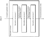
- An information processing device pertaining to an eighth aspect of the present invention includes: a protection control module operable to protect applications; and a plurality of detection modules, the protection control module comprising: a decrypter operable to execute a decryption process made up of k sub-processes on an application in encrypted form; and a distributor operable to distribute k pieces of verification target data that are the respective output data of the k sub-processes to the detection modules, wherein each of the detection modules comprises a verifier operable to determine whether or not the verification target data distributed thereto is correct by using (i) the distributed verification target data, (ii) input data for each of the sub-processes corresponding to the verification target data, and (iii) verification data generated according to the input data and output data expected to result from normal operation of the decrypter.
- each of the detection modules verifies the application decryption process performed by the protection control module without using the data of the protection control module itself. As such, the detection modules can be prevented from leaking confidential data by the protection control module.
- the detection modules perform verification on different sub-processes, and thus, the detection modules can be prevented from leaking the application data.
- a compromised sub-process can be detected within the whole.
- the protection control module comprises: plurality of applications; a verification source data holder holding k pieces of verification source data therein; and a verification data generator operable to generate k pieces of verification data from the k pieces of verification source data for distribution to the detection modules, the k pieces of verification source data include, for each of the applications, the following (i), (ii), and (iii) corresponding to each of the k sub-processes: (i) an application in encrypted form, (ii) a verification value indicating a correspondence between input data and output data for the sub-process as expected from normal operations of the decrypter, and (iii) a concatenated data verification value generated from the concatenated data of a plurality of verification values, and the verification data generator generates k pieces of verification data from the k pieces of verification source data by deleting therefrom verification values corresponding to an application being decrypted by the decrypter as well as the data of all other applications in encrypted form
- the verifier of each of the detection modules generates a verification value from the verification target data and from the data of the applications in encrypted form included in the received verification data, generates combined data by combining the verification value so generated and the verification values included in the received verification data, generates a combined data verification value from the combined data, and verifies whether or not there is a match between the combined data so generated and the combined data verification value included in the received verification data.
- the protection control module distributes verification data among the detection modules disclosing only the information pertaining to the application decrypted by the protection control module.
- unnecessary disclosure of information to the detection modules e.g. information pertaining to other applications
- Each of the detection modules uses the received verification data to perform verification on the protection control module.
- each of the detection modules deletes the received verification data after verification by the verifier, and confirms whether or not another detection module has deleted the verification data received thereby.
- verification data does not accumulate in the detection modules and thus, protection control module information, application information and the like can be prevented from leaking therefrom.
- each of the detection modules comprises a mutual surveillance unit operable to perform tamper verification on the other detection module, and if tampering is detected by the mutual surveillance unit, the detection module determines that the verification data have not been deleted by the other detection module, and if tampering is not detected, the detection module determines that the verification data have been deleted by the other detection module.
- the detection modules are able to delete the verification data (with a deletion program).
- the deletion program can be guaranteed to operate normally to delete the verification data.
- An information processing device pertaining to a thirteenth aspect of the present invention includes: a protection control module operable to protect applications; and a plurality of detection modules, the protection control module comprising: a processor operable to perform a predetermined process on input data and to output resulting output data; a challenge data receiver operable to receive challenge data from each of the detection modules; and a transmitter operable to transmit response data to each of the detection modules, the response data being the output data from the processor in response to the challenge data input thereto, each of the detection modules comprising: a holder that holds therein verification data showing, for each piece of challenge data, a correspondence between (i) the output data expected to result from normal operation of the processor when the piece of challenge data is input thereto and (ii) the challenge data; a challenge data transmitter operable to transmit one piece of challenge data to the protection control module, a response data receiver operable to receive the response data from the protection control module; and a verifier operable to verify the response data so received using the verification data, wherein at least two of the detection modules
- the verification data include a plurality of pieces of challenge data
- the challenge data transmitter selects one piece of challenge data from the challenge data included in the verification data and transmits the selected piece of challenge data to the protection control module.
- each detection module verifies the process performed by the protection control module without using the data of the protection control module itself.
- the detection modules can be prevented from leaking confidential data held by the protection control module.
- each of the detection modules can be prevented from leaking the application data.
- the protection control module generates ordering information indicating a processing order for the k sub-processes, and transmits the ordering information so generated to each of the detection modules, and the verifier of each of the detection modules verifies the verification target data according to the processing order indicated by the ordering information received thereby.
- each of the detection modules comprises: a verification target data receiver operable to receive verification target data from the detection module that performs a verification process as part of the sub-process immediately preceding the sub-process verified thereby; and a verification target data transmitter operable, when verification by the verifier is successful, to identify the detection module that performs the verification process as part of the next sub-process with reference to the ordering information, and to transmit verification target data thereto, and the verifier performs the verification process using the verification target data received by the verification target data receiver.
- each of the detection modules further comprises: an input data verifier operable to verify whether or not there is a match between the verification target data received by the receiver and the input data; and a notifier operable, when the verification target data and the input data do not match, to make an outside notification to this effect.
- the decrypter can verify whether or not the k sub-processes have been executed in the correct order.
- the protection control module can be deemed to have performed an unauthorized operation and the management device can be notified to such effect.
- the verification data includes a digital signature of an external management device.
- the verification data is a digital signature of an external management device for the input data and the output data expected to result from normal operation of the decrypter.
- the validity of the verification data can be guaranteed.
- each of the detection modules comprises a transmitter operable to transmit verification results to an external management device, and at least one of the detection modules comprises an update module operable, when the external management device determines that tampering has occurred in the protection control module, to update the protection control module.
- an authorized external management device can use the verification process of each detection module to update the protection control module with a new protection control module if a determination has been made to the effect that tampering has occurred therein.
- the confidential data held by the applications can be protected from leaks.
- a management device pertaining to a twenty-first aspect of the present invention is connected to an information processing device that verifies a plurality of data blocks, the information processing device having: a decrypter operable to decrypt data input thereto in encrypted form and output decryption results as output data, and a splitter operable to split the output data into the data blocks, the management device comprising: a verification source data generator operable to generate verification source data from the input data and from each data block expected to result from normal operation of the decrypter; and a transmitter operable to transmit the verification source data to the information processing device.
- the information processing device uses verification source data generated by the management device and can thus verify the data blocks (or decryption process) so as to guarantee the validity thereof.
- a management device pertaining to a twenty-second aspect of the present invention further comprises: a receiver operable to receive verification results for each of the data blocks from the information processing device; a determiner operable to determine, from the verification results so received, whether or not tampering has occurred in the decrypter; and an update instructor operable, when the determiner makes an affirmative determination, to instruct the information processing device to update the decrypter.
- a decrypter in which tampering has occurred can be updated, thus preventing the information processing device from leaking confidential data.
- a management device pertaining to a twenty-third aspect of the present invention is connected to an information processing device that verifies each of a plurality of sub-processes, the information processing device having a decrypter operable to decrypt data input thereto in encrypted form through the plurality of sub-processes, the management device comprising: a verification source data generator operable to generate verification source data from the input data for the sub-processes and from the output data expected to result from normal operation of the decrypter for each of the sub-processes; and a transmitter operable to transmit the verification source data so generated to the information processing device.
- the decrypter of the information processing device decrypts a plurality of applications in encrypted form
- the verification source data generator generates a plurality of pieces of verification source data that include, for each of the applications, the following (i), (ii), and (iii) corresponding to each of the sub-processes: (i) an application in encrypted form, (ii) a verification value indicating a correspondence between input data and output data for the sub-process as expected from normal operations of the decrypter, and (iii) a combined data verification value generated from the combined data of a plurality of verification values.
- a management device pertaining to a twenty-fifth aspect of the present invention comprises a challenge data generator operable to generate a plurality of pieces of challenge data; a verification data generator operable to generate verification data showing a correspondence between each piece of challenge data and output data expected to result from normal operation of a predetermined process taking the challenge data as input data; and a transmitter operable to transmit the challenge data and the verification data to the information processing device.
- the information processing device uses verification source data generated by the management device and can thus verify each decryption sub-process so as to guarantee the validity thereof.
- Embodiment 1 an illegal module detection system 1 to which are applied an information processing device and a management device pertaining to the present invention.
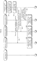
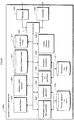
- Fig. 1 shows the overall configuration of the illegal module detection system 1.
- the illegal module detection system 1 comprises an apparatus 100, which is the information processing device pertaining to the present invention, and a management device 200 which is the management device pertaining to the present invention.
- the apparatus 100 and the management device 200 are connected via a network.
- the apparatus 100 provides various services to users via the network.
- the apparatus 100 can be used to access a content distribution server and then purchase and play back music and video content therefrom, or to access a financial institution system for online banking (such as balance inquiries and transfers), and so on.
- the apparatus 100 includes application 110, application 111, application 112, application 113, application 114, a protection control module 120, and a detection module group 130.
- Each of the applications 110, 111, 112, 113, and 114 consists of software that provides various functions to the user of the apparatus 100 via the network. Examples include software for purchasing music or video content from an undiagrammed content distribution server and playing back the content so purchased, software for accessing an undiagrammed financial institution system for balance inquires or money transfer, and so on.
- Each application has confidential data, such as authentication keys used for authentication by the content distribution server or financial institution system. Confidential data must be protected from malicious third parties (hereinafter referred to as attackers) attempting to extract data from the applications for illegal use.
- attackers malicious third parties
- the protection control module 120 is a module that controls functions for protecting each application from analysis by attackers attempting to extract confidential data, such as authentication keys, therefrom.
- the functions for protecting the applications include: a decryption loading function that encrypts and saves an application when not in use and decrypts the application only at use time, a tamper detecting function that checks whether or not an application has been tampered with (hereinafter termed compromised), and an analytic tool detecting function that checks for activity by analytic tools such as debuggers.
- the protection control module 120 controls the operation of these functions and checks whether or not each of the applications has been analyzed by attackers. When an attack is detected, the protection control module 120 stops the operation of the application where the attack was detected and prevents confidential data leaks through such processes as clearing the memory areas used by the application, particularly the memory areas where the confidential data was recorded (i.e. filling such memory areas with zeroes).
- the detection module group 130 is made up of three detection modules 131, 132, and 133.
- the detection modules 131, 132, and 133 determine whether or not the encrypted content decryption by the protection control module 120 has been performed correctly in order to verify whether or not the protection control module 120 has been compromised.
- detection modules 131, 132, and 133 perform mutual surveillance in order to prevent the detection modules themselves from being compromised and used in unauthorized ways by attackers.
- This mutual surveillance consists of the detection modules executing the tamper detection process on each other. Accordingly, the reliability of the apparatus 100 is improved as any attacks on a detection module included in the detection module group 130 can be detected.
- Each detection module transmits the verification results concerning the protection control module 120 as well as the results of the inter-modular mutual surveillance process to the management device 200 via the network.
- the reference signs may be omitted from the explanations when no particular one of the detection modules 131, 132, and 133 is designated.
- Fig. 2 is a functional block diagram showing the functional structure of the protection control module 120.
- the protection control module 120 comprises a receiver 301, a transmitter 302, a controller 303, a decryption loader 304, a tamper detector 305, an analytic tool detector 306, an encryption/decryption key holder 307, a verification source data holder 308, a verification data generator 309, and an application splitter 310.
- the receiver 301 receives distribution information and various requests from the detection modules.
- the transmitter 302 transmits requests and the like to the detection modules.
- the controller 303 controls the decryption loader 304, the tamper detector 305, and the analytic tool detector 306 to detect any attacks on the applications.
- the decryption loader 304 uses an encryption/decryption key to decrypt an encrypted application 110, 111, 112, 113, or 114 and load same into memory at execution time. Also, if a context switch to another application is triggered during execution of the application 110, 111, 112, 113, or 114, the decryption loader 304 uses the encryption/decryption key to encrypt the data loaded into memory. The encrypted data are later decrypted when the context switch returns to the application 110, 111, 112, 113, or 114.
- the tamper detector 305 detects whether or not tampering has occurred in each of the applications.
- the tamper detection process may be one of two methods, one of which involves the use of a tamper-detection certificate attached to each application while the other involves the comparison of MAC values.
- the analytic tool detector 306 detects the installation or operation of analytic tools such as debuggers and the like. An illicit attacker could plausibly install and operate analytic tools in order to attack the applications.
- the detection method may involve searching for file names, investigating whether or not any special registers used by debuggers have been used, detecting interrupts set by debuggers, and other such methods.
- the encryption/decryption key holder 307 holds the encryption/decryption key used to encrypt and decrypt the applications.
- the verification source data holder 308 holds verification source data received from the management device 200.
- the structure of the verification source data will be described later.
- the verification data generator 309 generates verification data from the verification source data held by the verification source data holder 308. The verification data generation process will be described later.
- the application splitter 310 splits the data of each application decrypted by the decryption loader 304.
- Fig. 3 is a functional block diagram showing the functional structure of detection module 131. Detection modules 132 and 133 share the same configuration as detection module 131.
- Detection module 131 comprises of a receiver 401, a transmitter 402, a controller 403, a verifier 404, a MAC value generator 405, a MAC value table updater 406, and a verification data holder 407.
- the receiver 401 receives various instructions from the management device 200. Also, the receiver 401 receives other detection modules as required in order to perform mutual surveillance therewith. Furthermore, the receiver 401 receives the results of processes requested from other modules, protection control module 120 verification results from other detection modules, and the like.
- the transmitter 402 transmits data, such as various process results, certificates, and the like, to the management device 200, the protection control module 120, and the other detection modules.
- the controller 403 controls the verifier 404 according to the instructions received by the receiver 401 to perform verification on the protection control module 120 and on the other detection modules.
- the verifier 404 uses the verification data held by the verification data holder 407 to verify whether the protection control module 120 is operating normally.
- the verifier 404 uses certificates attached to each of the detection modules, MAC values pre-calculated for use in verification, and the like to verify whether or not the detection modules have been compromised.
- the timing and the target module of the tamper detection process performed by the verifier 404 are preemptively assigned by the management device 200. If instructed by the management device 200 to change such parameters as the tamper detection target module or the timing at which tamper detection is performed, the verifier 404 does so accordingly.
- the MAC value generator 405 holds a verification key therein.
- the verifier 404 uses MAC values for the tamper detection process
- the MAC value generator 405 generates MAC values therefor using the verification key.
- the MAC value table updater 406 updates a MAC value table that contains the MAC value of each module.
- the MAC value table contains module identifiers identifying the modules and a MAC value corresponding thereto.
- the MAC value generator 405 acquires the module on which the tamper detection process is to be performed and calculates the MAC value thereof.
- the verifier 404 performs tamper detection by comparing the MAC value so calculated with the MAC value of the target module as stored in the MAC value table.
- the verification data holder 407 holds verification data for verifying whether or not the decryption loader 304 of the protection control module 120 is operating normally. The verification data are received by the protection control module 120.
- Non-Patent Literature 1 The details of the signature scheme are explained in Non-Patent Literature 1.
- the details of certificates, as well as those of the distribution information, are explained in Non-Patent Literature 2. Also, the details of the distribution information are discussed in Non-Patent Literature 2.
- the apparatus 100 includes a CPU (Central Processing Unit) 171, a non-volatile EEPROM (Electrically Erasable and Programmable Read-Only Memory) 172, RAM (Random Access Memory) 173, and a NIC (Network Interface Card) 174.
- the above are connected via a bus so as to communicate with one another.
- the EEPROM 172 stores therein the protection control module 120, detection modules 131, 132, and 133, as well as the applications.
- Each of the modules stored in the EEPROM 172 realizes all functions thereof in execution by the CPU 171.
- the specifics of each of the functions are described by computer programs.
- the RAM 173 is used as the work area of the CPU 171. Each detection module and each of the applications are loaded into the RAM 173. The detection module operating in the RAM 173 is the target of the tamper detection process.
- the NIC 174 is an expansion card for connecting to the network.
- the detection module group 130 is installed into an OS 180.
- Applications 110, 111, 112, 113, and 114 operate within the OS 180, while the protection control module 120 and a boot loader 150 are outside OS 180 control.
- the protection control module 120 and the detection module group 130 are run first, before any application is executed.
- the management device 200 generates the verification source data needed in order to verify whether or not the protection control module 120 is operating correctly, and then delivers these data to the apparatus 100.
- the management device 200 comprises a determiner 210, a verification source data distributor 220, and a communicator 230.
- the communicator 230 communicates with the apparatus 100 via the network. Secure communication channels, in which data are encrypted, may also be used for communication between the apparatus 100 and the management device 200.
- the management device 200 is a computer system that comprises a CPU, ROM, RAM, a hard disk unit, and so on.
- the management device 200 performs the above-described functions through operation by the CPU according to computer programs stored in ROM or on the hard disk unit.
- Fig. 6 is a functional block diagram showing the functional structure of the determiner 210. As shown, the determiner 210 comprises a receiver 501, a transmitter 502, an instruction generator 503, and a module identifier 504.
- the receiver 501 receives verification results and various requests from the detection modules and outputs these to the instruction generator 503. In addition, the receiver 501 notifies the instruction generator 503 upon receiving a process completion notification from the verification source data distributor 220.
- the transmitter 502 transmits instructions generated by the instruction generator 503 to the verification source data distributor 220.
- the instruction generator 503 outputs tamper detection results (hereinafter occasionally referred to as mutual surveillance results) received from the detection modules to the module identifier 504.
- the instruction generator 503 also acquires information from the module identifier 504 that identifies compromised detection modules, and then uses the information so acquired to generate instructions for the verification source data distributor 220.
- the instruction generator 503 generates instructions for the verification source data distributor 220 upon receiving a verification data generation request from the detection modules.
- the module identifier 504 identifies any unauthorized detection modules by using the mutual surveillance results received from the detection modules.
- the module identifier 504 outputs information identifying unauthorized detection modules to the instruction generator 503.
- the module identifier 504 identifies such detection modules as unauthorized.
- Fig. 7 is a functional block diagram showing the functional structure of the verification source data distributor 220.
- the verification source data distributor 220 comprises a receiver 601, a transmitter 602, a controller 603, an authenticator 604, a certificate generator 605, a private signature key holder 606, an encryption key holder 607, a data splitter 608, an application holder 609, a verification source data generator 610, and a protection control module holder 611.
- the receiver 601 receives protection control module verification results from the detection modules, as well as inter-modular mutual surveillance results.
- the transmitter 602 transmits tamper verification requests for each application and for the protection control module 120, mutual surveillance requests for the detection module group 130, the required verification source data, and the like to the apparatus 100.
- the controller 603 controls each component of the verification source data distributor 220.
- the authenticator 604 performs mutual authentication with each of the detection modules and with the protection control module 120.
- the certificate generator 605 uses the private signature key held by the private signature key holder 606 to generate signature data for the decryption loader 304 of the protection control module 120 to use in decrypting the encrypted applications.
- the private signature key holder 606 holds therein the private signature key of the management device 200. This key is used by the certificate generator 605 to generate signature data.
- the encryption key holder 607 holds an encryption key therein. This key is shared with the protection control module 120.
- the data splitter 608 splits the data output by the decryption loader 304 of the protection control module 120 upon decrypting the encrypted applications (decrypted plain-text application data) into multiple blocks.
- the application holder 609 holds therein each application installed on the apparatus 100.
- the verification source data generator 610 generates verification source data from the encrypted application data input to the decryption loader 304 (input data) and from the plain-text application data output from normal operations of the decryption loader 304 as split into blocks by the data splitter 608. The verification source data generator 610 then transmits the verification source data so generated to the apparatus 100. The structure of the verification source data will be described later.
- the protection control module holder 611 holds therein the protection control module 120 installed on the apparatus 100.
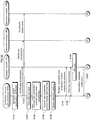
- Fig. 8 is a flowchart showing an outline of the overall operations of the illegal module detection system 1.
- an initial setup process is performed on the apparatus 100 upon factory assembly (step S1).
- the initial setup process involves loading all key data required to update the protection control module 120, as well as loading all data required after software updates (distribution information distributed using a private distribution method) and the like into each of the detection modules 131, 132, and 133.
- the apparatus 100 is shipped from the factory and provided to the user.
- the protection control module 120 within the apparatus 100 protects the applications against attackers. Also, the detection modules 131, 132, and 133 perform the detection process on the protection control module 120 (step S2).
- the illegal module detection system 1 also has the detection modules 131, 132, and 133 perform mutual surveillance in order to detect tampering. Mutual surveillance is regularly performed as part of the detection process in step S2.
- step S1 The initial setup process of step S1 is explained next.
- Fig. 9 is a sequence diagram showing the initial setup process. In the following, the process performed individually by each detection module is described as performed by the detection module group 130.
- the management device 200 transmits thereto the protection control module 120 held by the protection control module holder 611 and each of the applications held by the application holder 609 (step S11).
- the apparatus 100 installs the applications and protection control module 120 so received (step S12). In addition to the applications and the protection control module 120, the apparatus 100 also installs the detection modules 131, 132, and 133 and the software necessary for operations.
- the software so installed has a certificate attached thereto for verifying whether tampering has occurred (tamper detection certificate).
- the tamper detection certificate is signed with the private signature key of the management device 200.
- the apparatus 100 performs an initial setup process to test whether or not the software is operating properly (step S13).
- the detection module group 130 initializes the detection modules (step S14).
- the protection control module 120 requests dispatch of verification source data from the management device 200 (step S15). Upon receiving this request from the protection control module 120, the management device 200 generates the verification source data (step S16), and then transmits the verification source data to the protection control module 120 (step S17). The protection control module 120 then stores the verification source data received from the management device 200.
- step S14 The detection module initial setup process of step S14 is explained next.
- Fig. 10 is a flowchart showing the initial setup process for the detection module 131.
- Detection module 131 verifies the tamper detection certificate attached to another one of the detection modules which is the object of tamper detection (step S21).
- Verification of the tamper detection certificate proceeds by generating a verification value from the detection module data, and then comparing the verification value so generated to the verification value written in the certificate.
- a hash value, a signature, or the like may also be used as the verification value.
- the detection module 131 If the generated verification value and the verification value in the tamper detection certificate are found to match (Y in step S22), then the detection module 131 generates MAC values for the other detection modules and for the protection control module 120, respectively, and stores these in the MAC value holder (step S23).
- step S24 If the generated verification value and the verification value in the tamper detection certificate are found not to match (N in step S22), then an error is output and the process stops (step S24).
- step S16 The verification source data generation process of step S16 is explained next.
- Fig. 11 is a flowchart showing the verification source data generation process.
- the verification source data generator 610 encrypts the applications held by the application holder 609 using the encryption key held by the encryption key holder 607 (step S31).
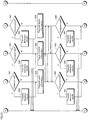
- the data splitter 608 splits the data of each application as shown in Fig. 12 (step S32).
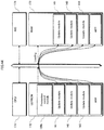
- the splitting method involves splitting application data loaded in memory into blocks that are either uniformly-sized or variably-sized.
- the application data may be split through division by a plurality of divisors.
- the Chinese remainder theorem may be used to ensure that the application data so split can be recovered.
- the Chinese remainder theorem is described on page 15 of Non-Patent Literature 1.
- the application data is split into three blocks.
- the verification source data generator 610 generates certificates that show the correspondence between the encrypted application and each data block (block 1, block 2, and block 3) split by the data splitter 608 (step S33). In addition, the verification source data generator 610 generates verification source data including the certificates generated in step S33 (step S34).
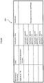
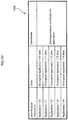
- the verification source data are described with reference to Figs. 13 , 14 , and 15 .
- the certificate 701 illustrated in Fig. 13 shows the correspondence between the encrypted application and data block 1.
- the certificate 702 illustrated in Fig. 14 shows the correspondence between the encrypted application and data block 2.
- the certificate 703 illustrated in Fig. 15 shows the correspondence between the encrypted application and data block 3.
- Each certificate is made up of block information, judgment information, and identification information, as well as encrypted application data and verification values corresponding thereto for every application, and finally a decryption process certificate for the block.
- the block information indicates which portions of all data are included in a given block.
- block information 1 indicates (3,1) or the like. This shows that the data in question belongs to the first of three blocks.
- block information 2 is (3,2)
- block information 3 is (3,3).
- the block information indicates something like (3,17). This shows that there are three blocks in all and that the length value is 17.
- the block information is not limited to these possibilities. Any information that serves to distinguish each of the data blocks from one another may be used.
- the judgment information is used to judge whether or not verification has been performed on all of the data blocks. For example, if the application data has been split into three blocks of uniform size, then the number of blocks is indicated as "3". Accordingly, if three different blocks are found, it follows that all blocks have been verified. Alternatively, if the application data has been divided by the divisors 7, 11, and 17, then the multiplied value of 7, 11, and 17, i.e. "1309", is indicated. Thus, the Chinese remainder theorem is satisfied.
- RSA encryption is discussed on pages 110 through 113 of Non-Patent Literature 1.
- the judgment information can be held by each of the detection modules instead of being included in the certificates.
- one detection module may hold the judgment information and transmit the judgment information to the other detection modules.
- the verification values are hash values of data combining the encrypted application data and the block data.
- the data used to calculate these hash values may also include the application identification information, the protection control module 120 identification information, and the like.
- the decryption process certificate is signature data generated using the private signature key of the management device 200 on a hash value calculated from the data of five combined verification values.
- the verification source data include the three certificates illustrated in Figs. 13 , 14 , and 15 .
- step S2 The detection process of step S2 is explained below.
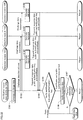
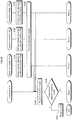
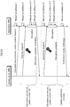
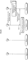
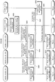
- Figs. 16 and 17 are sequence diagrams showing the detection process.
- the protection control module 120 Upon receiving a command to execute application 110, the protection control module 120 decrypts encrypted application 110 with the decryption loader 304 (step S41).
- the application splitter 310 splits the decrypted application 110 according to the block information included in the verification source data held by the verification source data holder 308 (step S42). If the block information indicates three blocks, then the application is split into three.
- the following explanations describe an application split into three.
- the protection control module 120 distributes the application identification information, the data blocks, and the verification data corresponding thereto to the detection modules.
- the verification data consist of the certificates shown in Figs. 13 through 15 .
- the verification data generator 309 selects a certificate corresponding to one of the blocks from the verification source data held by the verification source data holder 308 and takes the selected certificate as verification data.
- the protection control module 120 transmits the application identification information, block 1, and the verification data (the certificate 701 from Fig. 13 ) to detection module 131 (step S43),transmits the application identification information, block 2, and the verification data (the certificate 702 from Fig. 14 ) to detection module 132 (step S44),and transmits the application identification information, block 3, and the verification data (the certificate 703 from Fig. 15 ) to detection module 133 (step S45).
- Each detection module uses the verification data to verify whether or not the application has been decrypted correctly by the protection control module 120 (step S46).
- each detection module generates a verification value from the encrypted application data included in the verification data and from the received block. Then, each detection module compares the verification value so generated to the value included in the verification data and determines whether or not the two values match. In addition, each detection module verifies the signature of the decryption process certificate.
- the protection control module 120 is judged to have been compromised (Y in step S47) and this result is transmitted to the determiner 210 (step S48).
- the protection control module 120 is judged to be uncompromised (N in step S47) and the block information included in the verification data is transmitted to the other detection modules (step S49).
- the detection modules then confirm whether or not all of the blocks transmitted from the protection control module 120 have been verified. The specifics are described below.
- Detection module 131 transmits block information 1 to detection module 132 and to detection module 133.
- Block information 1 shows that the block in question is the first of three blocks.
- Detection module 131 receives block information 2 from the detection module 132 and receives block information 3 from detection module 133. Detection module 131 sees that the application data is split into three by reference to the judgment information included in the verification data. Then, by checking the content of the received block information 2 and 3, detection module 131 can discover that the second and third data blocks have been verified by detection modules 132 and 133, respectively.
- each detection module is able to confirm that all blocks transmitted from the protection control module 120 have been verified by another one of the detection modules.
- step S50 If not all blocks have been verified, or if all blocks have been transmitted to a single detection module, then the protection control module 120 is judged as having performed an unauthorized operation and thus, as having been compromised (Y in step S50). This result is transmitted to the determiner 210 (step S51).
- the verification source data held by the protection control module 120 must be updated.
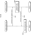
- the verification source data update process is explained through a specific example of the addition of a new application (hereinafter application 115) to the apparatus 100, described below with reference to the sequence diagram of Fig. 18 .
- the protection control module 120 receives the application 115 (step S61).
- the protection control module 120 encrypts the application 115 using the encryption/decryption key held by the encryption/decryption key holder 307 (step S62). Then, the protection control module 120 transmits the identification information of the application 115, the encrypted application 115 itself, and a verification source data dispatch request to the management device 200 (step S63).
- the management device 200 decrypts the encrypted application 115 with the encryption/decryption key of the protection control module 120 held by the protection control module holder 611. Then, the management device 200 generates new verification source data that includes the decrypted application 115 (step S64). Next, the management device 200 transmits the new verification source data to the protection control module 120 (step S65). Finally, the protection control module 120 receives and stores the new verification source data (step S66).
- Detection module 131 performs the tamper detection process on detection module 132 (step S71), detection module 132 performs the tamper detection process on detection module 133 (step S72), and detection module 133 performs the tamper detection process on detection module 131 (step S73).
- the tamper detection process of steps S71 through S73 is performed by calculating a MAC value for each detection module using the verification key and comparing the MAC values so calculated to the MAC values in the MAC value table.
- a hash value for each detection module may be used instead of the MAC values.
- step S74 If any detection module detects tampering (Y in step S74), this result is transmitted to the determiner 210 (step S75).
- the determiner 210 receives detection results from each detection module (step S76) and determines whether or not any of the detection modules have been compromised (step S77). If a compromised detection module is found (Y in step S77), then the determiner 210 notifies the apparatus 100 to stop the detection process (step S2) by the detection modules (step S78). If no compromised detection module is found (N in step S77), the process continues.
- the determiner 210 uses the results of the mutual surveillance process to determine whether or not the detection modules have been compromised.
- the determiner 210 is not limited in this manner and may also determine that a given detection module has been compromised if the above-described block verification results are not transmitted thereby.
- Embodiment 1 the encrypted application decryption process performed by the protection control module 120 is verified. This makes possible the determination of whether or not the protection control module 120 has been compromised without using the encryption/decryption key held thereby.
- each detection module verifies the blocks, thus making verification possible without any of the detection modules coming to know all of the application data.
- the information in the protection control module 120 and in the applications will not be leaked, even if a detection module is compromised and performs unauthorized operations.
- the security of the system is thus enhanced.
- Embodiment 2 of the present invention is presently explained.
- each detection module collects application data blocks, leaving a possibility that the application data may be leaked.
- Embodiment 2 in which the blocks and the verification data are deleted after block verification is complete, thus preventing application data leaks.
- Embodiment 2 also involves mutual confirmation of whether or not the blocks and the verification data have been deleted through mutual surveillance performed afterward.
- Embodiment 2 The detection process of Embodiment 2 is explained with reference to the sequence diagrams of Figs. 20 through 22 .
- the reference symbols of each component are identical to those used in Embodiment 1.
- steps S81 through S91 are identical to those of steps S41 through S51 of Embodiment 1 and are therefore omitted.
- Each of the detection modules deletes the received data block as well as the verification data held by the verification data holder 407 (step S92).
- the detection modules perform mutual tamper detection to confirm whether or not the blocks and the verification data have been deleted.
- detection module 131 performs the tamper detection process on detection module 132 (step S93), detection module 132 performs the tamper detection process on detection module 133 (step S94), and detection module 133 performs the tamper detection process on detection module 131 (step S95).
- the tamper detection process by each detection module is identical to the mutual surveillance tamper detection process.
- step S96 If any detection module detects tampering (Y in step S96), this result is transmitted to the determiner 210 (step S97).
- the determiner 210 receives the detection results from each detection module (step S98) and determines whether or not tampering has occurred in any detection module.
- step S100 If a detection module is found to have been compromised, then the determiner 210 considers the detection process by the protection control module 120 to have been performed improperly and calls for detection to performed anew (Y in step S99). The protection control module 120 is notified to this effect (step S100).
- the determiner 210 determines that the blocks and the verification data have been deleted.
- Embodiment 2 deletion of the blocks and of the verification data is performed and confirmed. Thus, even if one of the detection modules performs an unauthorized operation, only one block can be leaked. Further data blocks, as well as the complete application data, can be prevented from leaking.
- Embodiment 3 of the present invention is here described as a software update system.
- the software update system of Embodiment 3 updates a compromised protection control module, whenever found, with a new protection control module.
- Fig. 23 is a functional block diagram showing the functional structure of a protection control module 120a pertaining to Embodiment 3.
- the protection control module 120a comprises the components of the protection control module 120 (see Fig. 2 ) pertaining to Embodiment 1 and additionally includes an encryption/decryption key splitter 321, a certificate generator 322, and an encryption/decryption key recoverer 323.
- the encryption/decryption key splitter 321 uses a secret sharing scheme to generate distribution information from the encryption/decryption key at initial setup time and at subsequent-round preparation time.
- the certificate generator 322 holds the protection control module 120a private signature key. Using the private signature key, the certificate generator 322 generates a certificate used when the encryption/decryption key is restored from the distribution information to verify whether or not recovery has been performed correctly.
- the encryption/decryption key recoverer 323 obtains, from each update module, the distribution information that has been delivered thereto according to arrangement information.
- the encryption/decryption key recoverer 323 also recovers the encryption/decryption key from the distribution information so obtained and transmits the recovered key to the decryption loader 304.
- Fig. 24 is a functional block diagram showing the functional structure of detection module 131a pertaining to Embodiment 3.
- Detection module 131a includes all the components of detection module 131 ( Fig. 3 ) pertaining to Embodiment 1 with the addition of an updater 410 and a distribution information holder 411.
- the updater 410 collaborates with the management device 200 to update the software (all applications, the protection control module 120a, and all detection modules) of the apparatus 100.
- the distribution information holder 411 holds therein the distribution information, which is generated from the encryption/decryption key used by the protection control module 120a for encrypting and decrypting the applications, as well as arrangement information delivered therewith by the protection control module 120a.
- the arrangement information describes which portion of the distribution information was delivered to which of the detection modules.
- the authenticator 412 holds therein a pair of authentication keys (a private authentication key and a public authentication key) and performs authentication with the other modules.
- Fig. 25 is a functional block diagram showing the functional structure of the verification source data distributor 220a pertaining to Embodiment 3.
- the verification source data distributor 220a includes all the components of the verification source data distributor 220 pertaining to Embodiment 1 ( Fig. 7 ) with the addition of an encryption key generator 620, an encryption processor 621, and a detection module selector 622.
- the encryption key generator 620 generates an encryption key that is used when update software is transmitted to one of the detection modules.
- the encryption processor 621 uses the encryption key generated by the encryption key generator 620 to encrypt the update software.
- the encryption processor 621 also uses the detection module-exclusive key of the detection module selected by the detection module selector 622 to encrypt the aforementioned encryption key.
- the detection module selector 622 selects a detection module that will be used therefor.
- Fig. 26 is a flowchart showing the overall operations of the software update system.
- the software update system performs an initial setup process (step S101). Afterward, a verification process is performed by each of the detection modules on the protection control module 120a along with a detection process which determines whether or not the protection control module 120a has been compromised (step S102)
- the software update system performs an analysis/determination process that analyses the protection control module 120a and determines whether or not an update is required (step S103).
- the software update system has the detection modules and the verification source data distributor 220a perform mutual authentication to confirm whether or not all of the above have authorized software (step S104).
- the restoration process consists of installing the update protection control module onto the apparatus 100 after the mutual tamper detection process has been performed by the detection modules, and then using the distribution information embedded in each detection module to update the protection control module of the apparatus 100.
- step S106 the software update system prepares for the next time the protection control module will need an update by generating the key data and distribution information required therefor and embedding these into each detection module in a subsequent-round preparation process. Then, the software update system returns to the detection process of step S102 and continues the process.
- step S101 The initial setup operations of step S101 are explained below with reference to the sequence diagrams of Figs. 27 and 28 .
- steps S111 through S113 are identical to those previously explained for Embodiment 1 and are therefore omitted.
- the protection control module 120a generates distribution information from the encryption/decryption key using the secret sharing scheme (step S114). In addition, the protection control module 120a uses the private signature key to generate an encryption/decryption key certificate (step S115). The protection control module 120a then transmits the generated distribution information and encryption/decryption key certificate to the detection modules (step S116).
- the protection control module 120a transmits distribution information bundles to each of the detection modules such that the detection modules 131, 132, and 133 each come to hold a different bundle. Furthermore, the protection control module 120a transmits arrangement information to the detection modules that shows the distribution information transmitted to each of the detection modules. The arrangement information transmitted to each detection module is identical.
- the detection module group Upon receiving the distribution information, arrangement information, and encryption/decryption key certificate from the protection control module 120a, the detection module group performs a detection module initial setup process (step S117).
- Steps S118 through S121 of the protection control module 120a initial setup process are identical to those described in Embodiment 1 and are thus omitted.
- step S117 detection module initial setup process is explained next with reference to the flowchart shown in Fig. 29 .
- Detection module 131a receives the distribution information, the arrangement information, and the encryption/decryption key certificate from the protection control module 120a and stores these in the distribution information holder 411 (step S131). Subsequent operations are identical to those described in Embodiment 1 and are thus omitted.
- step S102 of Embodiment 3 is identical to that of Embodiments I and 2 and is thus omitted.
- step S103 The analysis/determination process of step S103 is described below with reference to the sequence diagram shown in Fig. 30 .
- Fig. 30 the process performed individually by each detection module is described as performed by the detection module group 130.
- the determiner 210 determines whether or not the protection control module 120a has been compromised according to the results so received (step S141).
- the determination method may, for example, be such that the protection control module 120a is judged to have been compromised if a predetermined number of detection modules detect tampering therein, and judged not to have been compromised if tampering is detected by less than the predetermined number of detection modules.
- the predetermined number may be more than half of the detection modules included in the detection module group 130.
- the presence of tampering in the protection control module 120a may be determined using the data blocks and the verification data upon reception thereof from each detection module.
- the determiner 210 requests notification of tamper information from the detection module group 130, which shows the portion of the protection control module 120a that has been compromised.
- the detection module group 130 collects tamper information (step S143) and notifies the determiner 210 thereof.
- the determiner 210 determines whether to restore the protection control module 120a, to revoke the apparatus 100, or to do nothing (step S144).
- step S144 If the protection control module 120a is to be restored (Y in step S144), then the determiner 210 prepares an updated protection control module (step S145) and instructs the detection module group 130 to begin the update process (step S146).
- step S141 If the protection control module 120a is deemed not to be compromised in step S141 (N in step S141), then the detection process resumes.
- step S104 is explained with reference to the sequence diagrams of Figs. 31 and 32 .
- the determiner 210 Upon determining, in the analysis/determination process, that the protection control module 120a is to be restored, the determiner 210 instructs the verification source data distributor 220a to restore the protection control module 120a.
- the verification source data distributor 220a After instructing the detection modules to begin the update process, the verification source data distributor 220a performs mutual authentication one-on-one with each detection module. Thus, the apparatus 100 is prevented from connecting to any unauthorized servers and the management device 200 is prevented from connecting to an illicit apparatus.
- the verification source data distributor 220a uses a private signature key and a public signature key, whereas each of the update modules uses a pair of authentication keys (a private authentication key and a public authentication key).
- Fig. 31 is a sequence diagram of detection module 131a authenticating the verification source data distributor 220a.
- Detection modules 132a and 133a operate similarly to detection module 131a as shown in Fig. 31 , also authenticating the verification source data distributor 220a.
- Detection module 131a uses a random number generator to generate random numbers (challenge data) (step S151) and then transmits the challenge data so generated to the verification source data distributor 220a (step S152). At this point, a detection module ID for identifying detection module 131a is transmitted along with the challenge data.
- the verification source data distributor 220a uses the private signature key on the received challenge data to generate signature data (step S153), and then returns the signature data so generated to detection module 131a as response data (step S154).
- detection module 131a Upon receiving the response data from the verification source data distributor 220a, detection module 131a uses the public signature key to verify whether or not the response data matches the signature data of the challenge data (step S155).
- detection module 131a If the verification results are such that the response data is correct and the verification source data distributor 220a is legitimate (Y in step S156), then detection module 131a continues the process. If the response data is incorrect and the verification source data distributor 220a is an unauthorized module (N in step S156), then detection module 131a outputs an error and stops the process.
- the verification source data distributor 220a authenticates detection modules 131a, 132a, and 133a.
- Fig. 32 is a sequence diagram of the verification source data distributor 220a authenticating the detection modules.
- the verification source data distributor 220a uses the random number generator to generate different random numbers (challenge data) for each detection module that has transmitted challenge data (step S161), and then transmits the challenge data so generated to each detection module, individually (step S162).
- Each detection module uses the private authentication key thereof on the received challenge data to generate signature data (step S163), then returns the signature data so generated to the verification source data distributor 220a as response data.
- each detection module transmits the public authentication key and authentication key certificate along with the response data to the verification source data distributor 220a (step S164).
- the verification source data distributor 220a receives the response data, public authentication key, and authentication key certificate from each of the detection modules.
- the verification source data distributor 220a verifies whether or not the authentication key certificate is the certificate originally issued thereby, and furthermore, uses the authentication key certificate to verify the validity of the public authentication key (step S165).
- step S165 If the authentication key certificate and the public authentication key are invalid (N in step S165), then the verification source data distributor 220a stops the process.
- the verification source data distributor 220a uses the public authentication key to verify whether or not the received response data match the signature data of the challenge data (step S166).
- the verification source data distributor 220a determines whether the number of detection modules that have returned correct response data (i.e. valid detection modules) is greater than the predetermined number required for the restoration process (step S167).
- step 167 If the number of valid detection modules is less than the number required for the restoration process (N in step 167), then the verification source data distributor 220a ends the process as restoration cannot be executed. If the number of valid update modules is sufficient for the restoration process (Y in step S167), then the mutual authentication process ends and the restoration process begins.
- the verification source data distributor 220a creates an authentication list during the mutual authentication process containing all module IDs belonging to detection modules confirmed to be valid. During the subsequent restoration process, only detection modules with IDs included on the authentication list will be used.
- step S105 involves updating the compromised protection control module 120a with a new updated protection control module if the above-described mutual authentication process succeeds.
- Fig. 33 is a flowchart showing the restoration process.
- the detection modules perform mutual surveillance (step S171).
- the mutual surveillance process involves tamper detection executed by each of the detection modules on the other detection modules.
- the protection control module 120a is updated using the updated pr otection control module (step S172).
- step S173 the encrypted applications 110, 111, 112, 113, and 114 are re-encrypted.
- Fig. 34 is a sequence diagram showing the details of the mutual surveillance process of step S171.
- Embodiment 3 The mutual surveillance process of Embodiment 3 is nearly identical to that of Embodiment 1, differing in that, in Embodiment 3, the detection modules constantly transmits tamper detection results to the determiner 210 (step S184).
- the restoration process stops at step S187 if any compromised detection modules are found.
- step S172 is explained in detail with reference to the sequence diagrams of Figs. 35 and 36 .
- the certificate generator 605 of the verification source data distributor 220a generates an update verification certificate using the private signature key (step S191).
- the update verification certificate exists so that the detection modules can confirm whether or not the new protection control module has been installed correctly.
- the verification source data distributor 220a transmits the certificate so generated to the detection modules (step S192).
- the encryption key generator 620 of the verification source data distributor 220a generates two encryption keys (a first key and a second key) which are used to multiply encrypt the new protection control module (step S193).
- the encryption processor 621 encrypts the new protection control module using the second key, thereby generating a new encrypted protection control module (step S194).
- the encryption processor 621 then further encrypts the new encrypted protection control module using the first key, thus generating a multiply-encrypted new protection control module (step S195).
- the verification source data distributor 220a selects one valid detection module from the detection module group 130 (step S196) and notifies the determiner 210 of the ID of the selected module.
- detection module 131a is selected.
- the verification source data distributor 220a transmits the multiply-encrypted new protection control module to the selected detection module 131a (step S197) and additionally transmits the first key thereto (step S198).
- Detection module 131a receives the multiply-encrypted new protection control module and the first key. Detection module 131 uses the first key to decrypt the multiply-encrypted new protection control module and thus acquires the new encrypted protection control module (step S199). Then, once decryption is complete, the verification source data distributor 220a is notified to such effect (step S200).
- the verification source data distributor 220a selects a valid detection module other than the detection module selected in step S196 from the detection module group 130 (step S201). In this example, detection module 132a is selected.
- the verification source data distributor 220a transmits the second key to the selected detection module 132a (step S202).
- the verification source data distributor 220a transmits the second key to the selected detection module 132a (step S202).
- the verification source data distributor 220a also requests that detection module 131a transmit the new encrypted protection control module obtained in step S199 to detection module 132a (step S203).
- detection module 131a Upon receiving the request from the verification source data distributor 220a, detection module 131a transmits the new encrypted protection control module to detection module 132a (step S204).
- Detection module 132a receives the second key from the verification source data distributor 220a and receives the encrypted new protection control module from detection module 131a. Then, detection module 132a decrypts the encrypted new protection control module using the second key, thus acquiring the new protection control module (step S205).
- Detection module 132a overwrites and updates the protection control module 120a with the new protection control module acquired in step S205 (step S206). Then, detection module 132a notifies the other detection modules that the update is complete (step S207).
- each detection module confirms that the protection control module update is indeed complete. Unlike the verification described in Patent Literature 3, Embodiment 3 confirms update completion by executing a decryption process on the new protection control module after the update process itself.
- Each detection module uses previously-received verification data for confirmation.
- Such data consist of a verification value and encrypted random numbers.
- the encrypted random numbers are data generated by encrypting random numbers with the encryption key of the new protection control module.
- the verification value is signature data generated using the private signature key.
- Each of the detection modules transmits the respective encrypted random numbers of the verification data thereof to the updated protection control module (step S208).
- the protection control module decrypts the received encrypted random numbers (step S209) and transmits the decrypted data acquired therefrom to the respective detection modules (step S210).
- each detection module Upon receiving the decrypted data from the protection control module, each detection module uses the verification value within the verification data to verify the received data (step S211). Each detection module notifies the verification source data distributor 220a of the verification results (step S212).
- the verification source data distributor 220a Upon receiving the verification results transmitted from the detection modules, the verification source data distributor 220a judges therefrom whether or not the protection control module was updated correctly (step S213). If judgment is negative (N in step S213), then the verification source data distributor 220a stops the apparatus 100.
- step S213 If judgment is affirmative (Y in step S213), then the verification source data distributor 220a notifies the detection modules that the update process is complete (step S214).
- the mutual surveillance process is executed regularly (i) when multiple keys are sent from the verification source data distributor 220a to one of the detection modules in the detection module group 130, and (ii) during the decryption process of the encrypted updated protection control module by the detection modules in the detection module group 130.
- the time interval of such regular execution may, for example, be shorter than the time until the updated protection control module is completely output via communication channels. If, for instance, the time required for complete output is one second, then surveillance may be executed at yet-shorter 500 ms intervals.
- the apparatus 100 executes mutual surveillance (mutual surveillance 1). This is done to ensure that an illicit detection module is not selected in the update process.
- the apparatus 100 executes mutual surveillance (mutual surveillance 2) confirming that an illicit detection module is not selected when the apparatus 100 receives the first key.
- detection module 131a receives the first key, mutual surveillance is regularly executed by pausing the decryption process by detection module 131a while the multiply-encrypted new protection control module is being decrypted thereby with the first key (mutual surveillance 3-1 and 3-2). Accordingly, even if detection module 131a, 132a, or 133a is attacked during the decryption process, such an attack can be detected before the new encrypted protection control module is fully leaked, thus making leak prevention possible.
- the apparatus 100 executes mutual surveillance (mutual surveillance 4) confirming that an illicit detection module is not selected when the apparatus 100 receives the key.
- detection module 132a receives the first key, mutual surveillance is regularly executed by pausing the decryption process by detection module 132a while the new encrypted protection control module is being decrypted thereby with the second key (mutual surveillance 5-1 and 5-2). Finally, mutual surveillance is executed (mutual surveillance 6).
- any attack on the decryption modules can be detected before the new protection control module is fully leaked, thus making leak prevention possible.
- the management device 200 can cancel the transmission of the first and second keys, and attackers will be unable to obtain the keys that decrypt the multiply-encrypted protection control module.
- step S173 the re-encryption process of step S173 is explained in detail with reference to the sequence diagrams of Fig. 38 .
- the updated protection control module requests transmission of the distribution information and the encryption/decryption key certificates respectively held by the detection modules 131a, 132a, and 133a (step S221).
- each detection module Upon receiving such a request from the protection control module, each detection module transmits the distribution information and the encryption/decryption key certificate (step S222).
- the protection control module receives the distribution information and the encryption/decryption key certificate from each update module, then recovers the encryption/decryption key used by the pre-update protection control module 120a (hereinafter called the old encryption/decryption key) from the received distribution information (step S223).
- the protection control module uses the encryption/decryption key certificates to verify whether or not the old encryption/decryption key has been recovered correctly (step S224).
- the protection control module exposes the illicit detection module (by specifying which of the detection modules transmitted the illicit distribution information) (step S225).
- the management device 200 is notified of the illicit detection module so specified.
- step S224 If the old encryption/decryption key has been recovered correctly (Y in step S224), then the protection control module generates a new encryption/decryption key. Then, the decryption loader decrypts the encrypted applications using the old encryption/decryption key and then re-encrypts the applications with the new encryption/decryption key (step S226).
- the protection control module collects a bundle of distribution information from each of the detection modules and adds identification information that identifies the detection modules thereto.
- this distribution information is placed into groups with the distribution information of the same values delivered at initial setup time. Then, the distribution information values in each group are compared, and distribution information bundles with the same values are further placed into a single sub-group. Subsequently, each sub-group is selected from the whole one at a time to generate all possible combinations.
- the old encryption/decryption key is generated for each such combination and verification is performed to ensure that the old encryption/decryption key generated therefrom is valid. If verification succeeds, identification information indicating that the sub-group has successfully passed through verification is attached to the sub-group included in the combination.
- any distribution information included in a sub-group that has had such identification information attached thereto is removed.
- any remaining distribution information is an illicit value.
- the detection module that transmitted the illicitly-valued distribution information can be specified through the identification information attached to such distribution information.
- the detection module specified by the identification information is specified as being an illicit detection module.
- step S106 is explained in detail with reference to the sequence diagram of Fig. 39 .
- the subsequent-round preparation process takes place after the restoration process as preparation for the next restoration process. The specifics are described below.
- the post-update protection control module generates distribution information from the new encryption/decryption key using the secret sharing scheme (step S231) and further generates a new encryption/decryption key certificate using the private signature key (step S232). Then, the protection control module transmits the distribution information and the encryption/decryption key certificate so generated to detection modules 131a, 132a, and 133a (step S233).
- the pieces of distribution information here generated match the detection modules in number such that each of the detection modules comes to hold a different pair of distribution information pieces. Identical new encryption/decryption key certificates are transmitted to all detection modules.
- Detection modules 131a, 132a, and 133a each receive the distribution information and the new encryption/decryption key certificates from the protection control module and store these in the respective distribution information holders 411 thereof (step S234).
- the protection control module transmits the application identification information, the encrypted applications, and a verification source data dispatch request to the management device 200 (step S235). Then, the management device 200 generates the verification source data (step S236).
- the verification source data generation process in the subsequent-round preparation process is slightly different from that of the initial setup process.
- the verification source data generation process within the subsequent-round preparation process involves using the new encryption/decryption key generated in the update process to decrypt the encrypted applications.
- the process of generating verification source data from the encrypted applications and the decrypted applications is substantially similar to the verification source data generation process performed in the initial setup process and is thus omitted.
- the management device 200 transmits the verification source data so generated to the protection control module (step S237), which in turn stores the received verification source data therein (step S238).
- Embodiment 3 if tampering is detected in the protection control module 120a during the detection process, then the protection control module is updated, thus enhancing system security.
- Embodiment 4 of the present invention is here described as an illegal module detection system 2.
- Embodiment 4 a mechanism for updating a protection control module in which tampering has been detected with a new protection control module, as well as a mechanism for invalidating any update modules detected as being illicit are described in detail. Portions duplicated in Embodiments 1 through 3 are here omitted for simplicity.
- Fig. 40 shows the overall configuration of the illegal module detection system 2.
- the illegal module detection system 2 comprises an apparatus 100b and an update server 200b.
- the apparatus 100b and the update server 200b are connected via a network.
- the apparatus 100b provides various services to users via the network.
- the apparatus 100b includes application 110, application 111, a protection control module 120b, an update module group 130b, and an access control module 140.
- Application 110 and application 111, as well as the protection control module 120b, are broadly similar to those of the above-described Embodiments 1 through 3.
- the update module group 130b is made up of a plurality of update modules.
- the update module group 130b comprises three update modules, namely update module 141, update module 142, and update module 143.
- Each update module detects the presence of tampering in the protection control module 120b. If the protection control module 120b is compromised, then each update module is able to download an updated protection control module from the update server 200 and update the compromised protection control module therewith.
- the update modules 141, 142, and 143 may also be operable to update the applications 110 and 111.
- the update modules perform mutual tamper detection within the update module group 130b.
- the tamper detection results are transmitted to the update server 200. If a given update module is deemed compromised by the update server 200, the other, normal update modules receive an invalidation instruction from the update server 200 and invalidate the compromised update module.
- the attack can be detected and contained.
- the access control module 140 holds therein access information necessary for the update modules to delete other update modules.
- This access information may be, for example, the address at which the module to be deleted can be found, a procedure describing the steps required for deletion, or similar.
- the access information is encrypted with an individual access information acquisition key for each respective module to be deleted.
- update modules 141, 142, and 143 The details of update modules 141, 142, and 143 are explained below.
- Fig. 41 is a functional block diagram showing the functional structure of update module 141. Update modules 142 and 143 share the same configuration as update module 141.
- Update module 141 comprises a receiver 801, a transmitter 802, a controller 803, an updater 804, a verifier 805, a MAC value generator 806, a MAC value table updater 807, and a distribution information holder 808.
- update module 141 has identical functions to those of detection module 131a from Embodiment 3 ( Fig. 24 ).
- Fig. 42 is a functional block diagram of the protection control module 120b.
- the protection control module 120b comprises a receiver 901, a transmitter 902, a controller 903, a decryption loader 904, a tamper detector 905, an analytic tool detector 906, an encryption/decryption key holder 907, an encryption/decryption key generator 908, an encryption/decryption key splitter 909, a certificate generator 910, and an encryption/decryption key recoverer 911.
- the components of the protection control module 120b have identical functions to those of the protection control module 120a from Embodiment 3 ( Fig. 23 ).
- the encryption/decryption key generator 908, not featured in Fig. 23 generates an encryption/decryption key for encrypting and decrypting applications 110 and 111.
- Fig. 43 is a functional block diagram showing the functional structure of the access control module 140.
- the access control module 140 comprises a receiver 1001, a transmitter 1002, and an access information holder 1003.
- the receiver 1001 receives acquisition requests from the update modules 141, 142, and 143 for access information required in order to delete a compromised update module.
- the transmitter 1002 transmits the access information to the update module making the request.
- the access information holder 1003 holds therein the access information for deleting the update modules 141, 142, and 143.
- Each piece of access information has an update module ID affixed thereto in order to identify the update module deletable thereby.
- each piece of access information is encrypted using the access information acquisition key.
- the access information holder 1003 Upon receiving an access information acquisition request from update module 141, 142, or 143, the access information holder 1003 transmits the access information to the requesting update module with the ID of the update module to be deleted attached thereto.
- the apparatus 100b includes a CPU 171, a non-volatile memory EEPROM 172, RAM 173, and a NIC 174. All of the above are connected via a bus so as to communicate with one another.
- the EEPROM 172 contains therein the protection control module 120b, the update modules 141, 142, and 143, as well as the applications 110 and 111.
- Each of the modules stored in the EEPROM 172 realizes all functions thereof in execution by the CPU 171.
- the specifics of each of the functions are described by computer programs.
- the RAM 173 is used as the work area for the CPU 171.
- the update modules 141, 142, and 143, as well as the applications 110 and 111, are loaded into the RAM 173.
- the update modules operating in the RAM 173 are the target of the tamper detection and invalidation processes.
- the NIC 174 is an expansion card for connecting to the network.
- the access control module 140 and the update module group 130b are installed into an OS 180.
- Applications 110 and 111 operate within the OS 180, while the protection control module 120b and a boot loader 160 are outside OS 180 control.
- the protection control module 120b and the update module group 130b are started first before any applications are executed.
- the update server 200b receives the tamper detection results from the update module group 130b of the apparatus 100b and functions accordingly as an illicit module specification device that specifies illicit update modules to be invalidated. Furthermore, the update server 200b additionally functions as a software delivery device that delivers software needed to update the software on the apparatus 100b (such as the protection control module 120b) thereto.
- the update server 200b comprises a determiner 210b, a communicator 230, an update software distributor 240, and a module invalidator 250.
- the update server 200b is a computer system that comprises a CPU, ROM, RAM, a hard disk unit, and so on.
- the update server 200b performs the above-described functions through operation by the CPU according to computer programs stored in ROM or on the hard disk unit.
- the determiner 210b receives the tamper detection results from the update module group 130b of the apparatus 100b and functions accordingly, specifying illicit update modules that must be invalidated.
- the communicator 230 transmits and receives information to and from each component of the apparatus 100b and the update server 200b. For example, the communicator 230 transmits the tamper detection results received from the apparatus 100b to the determiner 210b. Communication between the apparatus 100b and the update server 200b may also be performed via encrypted data or the like, and may use secure channels.
- the update software distributor 240 When updating the protection control module 120b, the update software distributor 240 operates in concert with the update modules 141, 142, and 143 to safely transmit the updated software to the apparatus 100b.
- the module invalidator 250 receives access information acquisition key requests from the update modules 141, 142, and 143, and then transmits the access information acquisition key to the requesting update module.
- Fig. 46 is a functional block diagram showing the functional structure of the determiner 210b.
- the determiner 210b comprises a receiver 1101, a transmitter 1102, an instruction generator 1103, and a module specifier 1104.
- the components of the determiner 210b have identical functions to those of the determiner 210 from Embodiment 1 ( Fig. 6 ).
- Fig. 47 is a functional block diagram showing the functional structure of the update software distributor 240.
- the update software distributor 240 comprises a receiver 1201, a transmitter 1202, an encryption key generator 1203, an encryption processor 1204, an authenticator 1205, an update module selector 1206, a controller 1207, a certificate generator 1208, a private signature key holder 1209, an update software holder 1210, and an encryption key holder 1211.
- the components of the update software distributor 240 have identical functions to those of the verification source data distributor 220a from Embodiment 3 ( Fig. 25 ).
- the update software holder 1210 olds therein an updated protection control module with which to update the protection control module 120b in case of an attack.
- Fig. 48 is a functional block diagram showing the functional structure of the module invalidator 250.
- the module invalidator 250 comprises a receiver 1301, a transmitter 1302, an access information acquisition key holder 1303, and an update module selector 1304.
- the receiver 1301 receives instructions from the determiner 210b to invalidate a compromised update module. In addition, the receiver 1301 receives acquisition requests for the access information acquisition key from the update modules 141, 142, and 143.
- the transmitter 1302 transmits the access information acquisition key to the requesting update module in response to such requests.
- the access information acquisition key holder 1303 holds therein the access information acquisition key that decrypts the access information held by the access control module 140.
- the update module selector 1304 selects an update module to perform invalidation on the compromised update module, and then instructs the selected update module to such effect.
- the transmitter 1302 attaches the ID of the update module that is to be deleted to the access information acquisition key and transmits the whole to the selected module.
- Fig. 49 is a flowchart showing the overall process flow of the illegal module detection system 2.
- the overall process for the illegal module detection system 2 is identical to that of Embodiment 2 ( Fig. 26 ).
- Fig. 51 is a sequence diagram showing the initial setup process.
- the illegal module detection system 2 installs all of the software into the non-volatile memory thereof.
- Fig. 50 is a schematic diagram of the keys embedded into the apparatus 100b.
- the update module group 130 includes update module 141 only.
- update modules 142 and 143 are also included therein, but are omitted.
- the encryption/decryption key is embedded into the protection control module 120b, whereas the public signature key, the verification key, and the pair of authentication keys are embedded into update module 141 (at this point in time, the distribution information bundle has not yet been embedded into the update module). Furthermore, update module IDs that identify each of the update modules are embedded into update module 141, which is installed in the apparatus 100b in this form.
- the encryption/decryption key is used to encrypt and to decrypt applications 110 and 111.
- the applications are encrypted using the encryption/decryption key and stored in non-volatile memory in encrypted form.
- the protection control module 120b decrypts the applications using the encryption/decryption key before execution thereof.
- decryption occurs at context-switching time by using the encryption/decryption key to encrypt or decrypt the data used by the applications.
- an analytic tool such as a debugger
- the keys embedded into the update modules include a public signature key shared by all of the update modules.
- the verification key and the pair of authentication keys differ for each update module.
- steps S261 through S267 is identical to that of steps S113 through S117 of Embodiment 3 ( Fig. 27 ).
- Fig. 52 is a flowchart showing the update module initial setup process (step S267 from Fig. 51 ). Although Fig. 52 describes update module 141, the operations of update module 142 and 143 are essentially identical.
- the update module initial setup process is identical to that of Embodiment 3 ( Fig. 29 ).
- step S252 from Fig. 49 The details of the detection process (step S252 from Fig. 49 ) performed by the illegal module detection system 2 is explained below with reference to the sequence diagram of Fig. 53 .
- the apparatus 100b is shipped from the factory and sent to the user.
- the protection control module 120b within controls the decryption loading function, the tamper detecting function, the analytic tool detecting function, and so on, in order to protect the application from attacks.
- Embodiment 4 The detection process of Embodiment 4 is different from that of Embodiments I through 3.
- each of the update modules performs tamper detection on the protection control module 120b (step S281).
- This tamper detection process is performed by using the verification key to calculate the MAC value of the protection control module 120b, and then comparing the MAC value so calculated to that held in the MAC value table.
- the protection control module 120b is judged to be uncompromised. However, if the MAC values do not match, then the protection control module 120b is judged to be compromised.
- update module 141 is described as performing tamper detection on the protection control module 120.
- update modules 142 and 143 also perform the same process.
- step S282 Judgment of whether or not the protection control module 120b has been compromised, i.e. of whether or not the MAC values match, is made (step S282). Then, if the protection control module 120b is judged to be compromised (Y in step S282), update module 141 notifies the determiner 210b of the update server 200b and the other update modules to such effect (step S283).
- update module 141 resumes the tamper detection process without notifying the determiner 210b or the other update modules.
- An update module receiving notification from another update module that the protection control module 120b has been compromised uses the verification key and MAC value to perform tamper detection thereon (steps S284 and S286).
- the determiner 210b and the other update modules are then notified of the tamper detection results (steps S285 and S287).
- Fig. 54 is a sequence diagram showing the analysis/determination process (step S253 in Fig. 49 ).
- Fig. 54 illustrates the process performed individually by each update module 141, 142, and 143 as performed by the update module group 130b.
- Figs. 55 and 56 are sequence diagrams showing the operational flow of the mutual authentication process in the illegal module detection system 2.
- the determiner 210b determines that the protection control module 120 must be restored, then the determiner 210b instructs the update software distributor 240 to such effect. After instructing the update modules to begin the update process, the update software distributor 240 performs mutual authentication with each of the update modules one-on-one.
- Fig. 55 shows the process of the update module 141 authenticating the update software distributor 240. Although only update module 141 is presently described, the other update modules operate identically.
- update module 141 authenticating the update software distributor 240 are identical to those shown in Fig. 31 for Embodiment 3, where detection module 131a authenticates the verification source data distributor 220a.
- Fig. 56 shows the process of the update software distributor 220 authenticating the update modules.
- the operations of the update software distributor 240 authenticating each of the update modules are identical to those shown in Fig. 32 for Embodiment 3, where the verification source data distributor 220a authenticates each of the update modules.
- Fig. 57 is a flowchart showing the illegal module detection system 2 restoration process (step S255 in Fig. 49 ).
- the restoration process involves updating the compromised protection control module 120b with a new updated protection control module if the mutual authentication succeeds.
- the restoration process includes a mutual surveillance process (step S321), an update process (step S322), and a re-encryption process (step S323).
- Fig. 58 is a sequence diagram showing the mutual surveillance process (step S321 in Fig. 57 ).
- the mutual surveillance process is a tamper detection process executed by update modules 141, 142, and 143 on other the update modules in the update module group 130b.
- the update module on which each update module performs the tamper detection process follows a surveillance pattern held therein.
- the surveillance pattern contains information pertaining to the modules on which tamper detection is to be performed (such as module ID, location in memory, size, address, file name, and the like).
- Embodiment 4 The mutual surveillance process of Embodiment 4 is identical to that of Embodiment 3 ( Fig. 34 ).
- step S322 in Fig. 57 is explained in detail using the sequence diagrams of Figs. 59 and 60 .
- Steps S341 through S357 are identical to steps S191 through S207 of Embodiment 3 ( Figs. 35 and 36 ).
- Each of the update modules 141, 142, and 143 uses the previously-received update verification certificate to verify whether the protection control module has been updated correctly (step S358), then notifies the update software distributor 240 of the verification results (step S359).
- the update software distributor 240 determines, from the verification results so received, whether the protection control module was updated correctly (step S360).
- step S360 If this judgment is negative (N in step S360), then the update software distributor 240 stops the apparatus 100b.
- step S360 If the judgment is affirmative (Y in step S360), then the update software distributor 240 notifies the update modules that the update process is complete (step S361).
- each of the update modules Upon receiving notification that the update process is complete, each of the update modules generates a MAC value for the new protection control module (step S362), and then writes the MAC value so generated in a bundle with the protection control module ID into the MAC value table.
- Fig. 61 is schematic diagram showing the coordinated operations of the mutual surveillance process and the update process. The details have already been described in Embodiment 3 ( Fig. 37 ) and are thus omitted.
- Fig. 62 is a sequence diagram showing the re-encryption process (step S323 in Fig. 57 ).
- the re-encryption process of Embodiment 4 is identical to that of Embodiment 3 ( Fig. 38 ).
- Fig. 63 is a sequence diagram showing the subsequent-round preparation process (step S256 in Fig. 49 ).
- the subsequent-round preparation process takes place after the restoration process as preparation for the next restoration process.
- the post-update protection control module generates distribution information from the new encryption/decryption key using the secret sharing scheme (step S381) and further generates a new encryption/decryption key certificate using the private signature key (step S382). Then, the protection control module transmits the distribution information and the encryption/decryption key certificate so generated to update modules 141, 142, and 143 (step S383).
- the pieces of distribution information here generated match the update modules in number such that each of the update modules comes to hold a different pair of distribution information pieces.
- Identical new encryption/decryption key certificates are transmitted to each of the update modules 141, 142, and 143.
- the update modules 141, 142, and 143 receive the distribution information and new encryption/decryption key certificate from the protection control module and hold these therein (step S384).
- the invalidation process invalidates any illicit (compromised) update modules found in the apparatus 100b whenever an update module fails authentication at mutual authentication time, a compromised update module is detected in the surveillance process during restoration, an illegal update module has been exposed in the re-encryption process during restoration, and in similar situations.
- update module 143 is compromised and has been respectively detected as such by update modules 141 and 142.
- the determiner 210b determines which update module is compromised according to the mutual surveillance results received from update modules 141, 142, and 143 (step S391). This determination is made by, for instance, deeming any update modules determined as compromised by more than half of the other update modules to be illicit.
- the determiner 210b outputs an invalidation instruction along with the ID of the compromised update module to the module invalidator 250 (step S392).
- the module invalidator 250 requests that one of the update modules deemed uncompromised, i.e. update module 141 or 142 (this example uses update module 141), invalidate the compromised update module 143 (step S393).
- update module 141 Upon receiving the request to invalidate update module 143 from the module invalidator 250, update module 141 requests the dispatch of the required access information acquisition key from the module invalidator 250 (step S394). Update module 141 further requests acquisition of the required access information from the access control module 140 (step S395).
- the module invalidator 250 Upon receiving the access information acquisition key dispatch request, the module invalidator 250 confirms whether or not update module 141 is a valid, uncompromised module, and whether or not the requested access information acquisition key is the one required to invalidate the compromised update module 143 (step S396). This confirmation is performed using the update module information of which the module invalidator 250 was notified by the determiner 210b.
- step S396 If the confirmation results are unproblematic (Y in step S396), then the access information acquisition key needed to invalidate update module 143 is dispatched to the requesting update module 141 (step S397).
- Update module 141 receives the access information acquisition key from the module invalidator 250 and also receives the encrypted access information from the access control module 140 (step S398). Update module 141 acquires the access information from the access information acquisition key and the encrypted access information (step S399). The access information so acquired is a specialized driver for deleting update module 143. Update module 141 uses this specialized driver to delete the compromised, illicit update module 143 (step S400).
- update module 141 deletes the access information acquisition key, the encrypted access information, the access information itself, and the like, and then transmits a completion notification to the module invalidator 250 (step S401).
- the module invalidator 250 Upon receiving the completion notification from update module 141, the module invalidator 250 transmits an invalidation completion notification to the determiner 210b (step S402).
- Pages 56 through 64 of Patent Literature 2 discuss the details of an invalidation method that takes this factor into account, known as a withdrawal process.
- Embodiment 5 of the present invention is presently explained.
- Embodiment 4 MAC values were used to verify whether or not the protection control module had been compromised.
- Embodiment 5 uses verification data output by the protection control module at application execution time for the same purpose.
- the illegal module detection system pertaining to Embodiment comprises an apparatus 100b and an update server 200b, much like that of Embodiment 4.
- the following explanations center on the points of difference thereof from Embodiment 4.
- Fig. 65 is a functional block diagram showing the functional structure of the protection control module 120c pertaining to Embodiment 5. Components thereof that are identical to those of Embodiment 4 have the same reference numbers and are omitted.
- protection control module 120c does not include an encryption/decryption key generator 908.
- protection control module 120c comprises a verification data generator 912 and a verification source data holder 913 lacked by protection control module 120b.
- the verification source data holder 913 holds therein verification source data received from the update server 200b.
- the verification data generator 912 generates verification data from the verification source data held by the verification source data holder 913, then transmits the verification data so generated to the update modules.
- Fig. 66 is a functional block diagram showing the functional structure of update module 141c pertaining to Embodiment 5. Components thereof that are identical to those of Embodiment 4 have the same reference numbers and are omitted.
- update module 141 further comprises a detector 810 and a verification data holder 811.
- the verifier 805 verifies whether the protection control module 120c and each of the update modules are operating normally.
- the verifier 805 uses pre-calculated MAC values and hash values to verify the update modules.
- the verifier 805 uses the detector 810 to verify the protection control module 120c. U pon receiving the verification data from the protection control module 120c, the verifier 805 stores the verification data in the verification data holder 811. Also, upon receiving the application decryption process output data from the protection control module 120c, the verifier 805 in turn outputs the output data to the detector 810. The verifier 805 then receives verification results indicating whether or not the protection control module 120c is operating normally from the detector 810.
- the detector 810 uses the output data received from the verifier 805 and the verification data stored by the verification data holder 811 to verify the signature included in the latter. By verifying the signature, the validity of the input/output correspondence of the application decryption process by the protection control module 120c is verified. The detector 810 then transmits the verification results to the verifier 805.
- the verification data holder 811 stores therein the verification data received from the verifier 805.
- Fig. 67 is a functional block diagram showing the functional structure of the update software distributor 240c pertaining to Embodiment 5. Components thereof that are identical to those of Embodiment 4 have the same reference numbers and are omitted.
- the update software distributor 240c further comprises an update software executor 1220, an application holder 1221, and a verification source data generator 1222.
- the update software executor 1220 uses the updated protection control module held by the update software holder 1210 to execute the encrypted application and to acquire input and output data from the decryption process.
- the application holder 1221 holds therein the applications installed on the apparatus 100b.
- the verification source data generator 1222 When the decryption loader 904 of the protection control module 120c is operating properly, the verification source data generator 1222 generates verification source data that guarantees the input/output correspondence of the encrypted application decryption process, and then transmits the verification source data so generated to the apparatus 100b. The details of the verification source data will be described later.
- Figs. 68 and 69 are flowcharts showing the initial setup process. The following explanations focus on the points of difference from Embodiment 4.
- the update server 200b transmits the protection control module 120c held by the update software holder 1210 to the apparatus 100b (step S501).
- Steps S502 through S511 are identical to those of Embodiment 4.
- the protection control module 120c makes a verification source data dispatch request to the update server 200b (step S512).
- the update server 200b generates the verification source data (step S513). Subsequently, the update server 200b transmits the verification source data so generated to the protection control module 120c (step S514).
- the protection control module 120 receives and stores the verification source data (step S515).
- Fig. 70 is a flowchart showing the initial setup process for the update modules.
- update module 141c verifies the tamper detection certificates of update module 142c and of update module 143c.
- step S522 update module 141c does not verify the tamper detection certificate of the protection control module 120c.
- Fig. 71 is a flowchart showing the verification source data generation process.
- the verification source data generator 1222 encrypts the applications installed on the apparatus 100b with the encryption/decryption key from the protection control module 120c (step S531).
- the verification source data generator 1222 generates a certificate (correspondence certificate) (step S532).
- This certificate is a signature generated using the private signature key in the private signature key holder 1209 of the update server 200 for the input and output data expected when the protection control module 120c is operating normally.
- the data input to the protection control module 120c are the encrypted applications, while the data output therefrom are the decrypted plain-text applications.
- the data that are the object of signature generation are not only the input and output data of the protection control module 120c but may also include the application identification information, or information indicating the content of the application (such as a DVD or BD playback application or an online banking application). Furthermore, the identification information of the protection control module 120c may also be included.
- the verification source data generator 1222 generates verification source data that is made up of the application identification information, the encrypted application data, and the certificate (step S533).
- Fig. 72 shows the structure of the verification source data.
- the verification source data 1200 comprises, for each of the applications, identification information, encrypted application data corresponding thereto, and a certificate.
- Fig. 73 is a sequence diagram showing the detection process.
- the protection control module 120c encrypts and protects the applications.
- the detection process of Embodiment 5 is characterized in that verification of the protection control module 120c is performed at application execution time.
- the protection control module 120c Upon receiving a command to execute application 110, the protection control module 120c transmits the verification data generated by the verification data generator 912, the identification information for application 110, and the decrypted application 110 itself to update module 141c (step S541).
- Fig. 73 shows only update module 141c verifying the protection control module 120c.
- update module 142c and 143c also perform the same process.
- Update module 141c uses the verification data to verify whether or not the input/output correspondence for the application 110 decryption process by the protection control module 120c is correct (step S542). To this end, update module 141c uses the data of the encrypted application 110 included in the verification data (input data) and the received decryption results (output data).
- update module 141c judges that the protection control module 120c is compromised and notifies the determiner 210b as well as the other update modules of these verification results (step S543).
- update module 141c re-verifies the protection control module 120c at the next application execution time without notifying the determiner 210b and the other update modules.
- update modules 142c and 143c request that the protection control module 120c transmit the application identification information, the decrypted application data, and the verification data (step S544).
- the protection control module 120c Upon receiving the transmission request from update modules 142c and 143c, the protection control module 120c transmits the application identification information, the decrypted application data, and the verification data (step S545).
- Update modules 142c and 143c respectively verify whether or not the input/output correspondence for the application 110 decryption process by the protection control module 120c is correct according to the received application identification information, decrypted application data, and verification data (step S546). Subsequently, update modules 142c and 143c transmit the verification results to the determiner 210b (step S547). Finally, the determiner 210b receives the verification results.
- Embodiment 5 when the protection control module 120c is to be updated with a new protection control module, the encryption/decryption key holder thereof is installed onto the apparatus 100b while holding a new encryption/decryption key generated by the update software distributor 240c.
- Fig. 74 is a sequence diagram showing the re-encryption process.
- the encryption/decryption key holder of the new protection control module already holds a new encryption/decryption key therein.
- the re-encryption process shown in Fig. 74 does not involve generation of a new encryption/decryption key as in step S376 of Embodiment 4 ( Fig. 62 ).
- the protection control module recovers the old encryption/decryption key and uses this key to decrypt the encrypted applications, then uses the new encryption/decryption key already held thereby to re-encrypt the applications (step S556).
- Fig. 75 is a sequence diagram showing the subsequent-round preparation process.
- the protection control module 120c After transmitting the distribution information and the encryption/decryption key certificate to the update modules in step S563, the protection control module 120c transmits a dispatch request for the application identification information, the encrypted application, and the verification source data to the update server 200b (step S567). Afterward, the update server 200b generates the verification source data (step S568).
- the verification source data generation process in the subsequent-round preparation process is slightly different from that of the initial setup process.
- the update server 200b uses the new encryption/decryption key generated in the update process to decrypt the received encrypted applications. Then, a certificate (correspondence certificate) is generated for each encrypted application and for each decrypted application. This certificate is a signature generated using the private signature key of the update server 200b.
- the structure of the verification source data is identical to that shown in Fig. 72 .
- the update server 200b then transmits the verification source data so generated to the protection control module (step S569). Finally, the protection control module receives and stores the verification source data (step S570).
- Fig. 76 is a sequence diagram showing the verification source data update process.
- the protection control module 120c within the apparatus 100b receives the downloaded application 115 (step S581).
- the protection control module 120c uses the encryption/decryption key to encrypt the application 115 so received (step S582).
- the protection control module 120c then transmits the application identification information, the encrypted application, and a verification source data dispatch request to the update server 200b (step S583).
- the update server 200b generates the verification source data (step S584).
- the verification source data generation process within the verification source data update process proceeds in the same manner as that of the above-described subsequent-round preparation process.
- the update server 200b uses the new encryption/decryption key generated in the update process to decrypt the received encrypted application.
- the update server 200b then generates a certificate (correspondence certificate) for the encrypted application and the decrypted application.
- This certificate is a signature generated using the private signature key of the update server 200b.
- the structure of the verification source data is identical to that shown in Fig. 72 .
- the update server 200b transmits the verification source data so generated to the protection control module 120c (step S585). Finally, the protection control module 120 stores the received verification source data in the verification source data holder 420 (step S586).
- Embodiment 5 the presence of tampering in the protection control module 120c is verified through verification of whether or not the protection control module 120c correctly executes the application decryption process.
- each update module can verify the protection control module 120c without knowledge of the data thereof. Therefore, supposing that an update module were to perform unauthorized operations, the data of the protection control module 120c can nevertheless be prevented from leaking, which in turn provides an additional layer of system security.
- Embodiment 6 of the present invention is presently explained.
- the following explanations use the same reference numbers as Embodiment 5.
- Embodiment 6 is characterized in that the application decryption process performed by the protection control module 120c is divided into a plurality of processes, and tampering is detected in the protection control module 120c through verification of the input/output correspondence for each such process.
- Fig. 77 shows the outline of the decryption process by the protection control module 120c as divided into a plurality of sub-processes.
- the decryption process is divided into three sub-processes, namely decryption sub-process 1, decryption sub-process 2, and decryption sub-process 3.
- Each update module uses the verification data generated in each decryption sub-process to verify the input/output correspondence thereof.
- having each of the three update modules verify a different one of the decryption sub-processes is preferable to having a single update module verify all three decryption sub-processes.
- Embodiment 6 the structure of the verification source data generated by the verification source data generator 1222 is different.
- Fig. 78 shows the structure of the verification source data for Embodiment 6.
- the verification source data 1300 includes data 1300a pertaining to decryption sub-process 1, data 1300b pertaining to decryption sub-process 2, and data 1300c pertaining to decryption sub-process 3.
- Data 1300a includes a correspondence certificate generated from, for all of the applications 110 through 114, identification information, encrypted application data corresponding thereto, and the encrypted data of the application itself, as well as from an intermediate value 1 which consists of the data output of decryption sub-process 1.
- Data 1300b includes a correspondence certificate generated from, for all of the applications 110 through 114, identification information, the data of intermediate value 1 corresponding thereto, and an intermediate value 2 which consists of intermediate value 1 and the data output of decryption sub-process 2.
- Data 1300c includes a correspondence certificate generated from, for all of the applications 110 through 114, identification information, the data of intermediate value 2 corresponding thereto, and the data of the decrypted application, which consists of intermediate value 2 and the data output of decryption sub-process 3.
- the update software executor 1220 acquires intermediate value 1, intermediate value 2, and the decrypted application data by decrypting the application.
- Each of the correspondence certificates is generated using the private signature key of the update server 200b for the input data and output data of each decryption sub-process when the protection control module 120c is operating normally.
- the correspondence certificate for decryption sub-process 1 is a signature generated using the private signature key of the update server 200b for the input data input as such for each encrypted application, and for the output data from normal operations of the protection control module 120c.
- the correspondence certificate for decryption sub-process 2 is a signature generated using the private signature key of the update server 200b for the input data input as such for the intermediate value 1 of each application, and for the output data from normal operations of the protection control module 120c.
- the correspondence certificate for decryption sub-process 3 is a signature generated using the private signature key of the update server 200b for the input data input as such for the intermediate value 2 of each application, and for the output data from normal operations of the protection control module 120c.
- Embodiment 6 The initial setup process of Embodiment 6 is identical to that of Embodiment 5 ( Figs. 68 and 69 ).
- the protection control module 120c transmitted from the update server 200b to the apparatus 100b during step S501 includes a decryption program that decrypts the encrypted applications in three decryption sub-processes.
- step S513 The details of the verification source data generation process from step S513 will be described later.
- Fig. 79 is a flowchart showing the verification source data generation process pertaining to Embodiment 6.
- the verification source data generator 1222 encrypts the applications held in the application holder 1221 with the encryption/decryption key of the protection control module 120c (step S601).
- the update software executor 1220 executes the protection control module 120c decryption process, thus decrypting the encrypted applications and acquiring intermediate values, i.e. the data output of each decryption sub-process, as well as the decrypted applications (step S602).
- the certificate generator 1208 uses the private signature key held by the private signature key holder 1209 to generate a certificate (correspondence certificate) for the combinations of (a) the encrypted application data and intermediate value 1, (b), intermediate value 1 and intermediate value 2, and (c) intermediate value 2 an the decrypted application data (step S603).
- the verification source data generator 1222 generates verification source data made up of the application identification information, the input data corresponding to each decryption sub-process, and the correspondence certificates (step S604).
- Figs. 80 and 81 are sequence diagrams showing the detection process pertaining to Embodiment 6.
- the protection control module 120c Upon receiving a command to execute application 110, the protection control module 120c generates verification data from the verification source data ( Fig. 78 ) held by the verification source data holder 913 (step S611).
- the verification data generator 912 generates verification data 1301 for decryption sub-process 1 as shown in Fig. 82 , verification data 1302 for decryption sub-process 2 as shown in Fig. 83 , and verification data 1303 for decryption sub-process 3 as shown in Fig. 84 .
- the protection control module 120c decrypts the encrypted application 110 (step S612).
- the protection control module 120c selects one of the update modules (in this example, update module 141c) and transmits thereto the application 110 identification information, intermediate value 1, and the verification data for decryption sub-process 1 (step S613).
- the protection control module 120c selects one of the update modules other than the previously-selected update module (in this example, update module 142c) and transmits thereto the application 110 identification information, intermediate value 2, and the verification data for decryption sub-process 2 (step S614).
- the protection control module 120c further selects one of the update modules other than the previously-selected two update modules (in this example, update module 143c) and transmits thereto the application 110 identification information, the decrypted application data, and the verification data for decryption sub-process 3 (step S615).
- each of the update modules uses the verification data so received to verify whether or not the input/output correspondence of the decryption sub-processes is correct (steps S616, S617, and S618).
- Fig. 81 shows the verification results notification made by update module 141c only. However, update modules 142c and 143c also make the same notification.
- the update modules re-verify the protection control module 120c when the next application is executed without notifying the determiner 210b or the other update modules.
- Embodiment 6 The subsequent-round preparation process of Embodiment 6 is identical to that of Embodiment 5 ( Fig. 75 ). However, in Embodiment 6, the verification source data generated by the update server 200b is the verification source data 1300 shown in Fig. 78 .
- the verification source data update process of Embodiment 6 is identical to that of Embodiment 5 ( Fig. 76 ). However, during the verification source data generation process within the verification source data update process of Embodiment 6, the update software executor 1220 acquires intermediate value 1, intermediate value 2, and the decrypted application data from the encrypted application data. Also, the verification source data generator 1222 generates the verification source data 1300 shown in Fig. 78 according to the data so acquired.
- the decryption process executed by the protection control module 120c is divided into sub-processes and verification of the input/output data correspondence is performed for each sub-process. Therefore, supposing that an update module were to perform unauthorized operations, the decryption process performed by the protection control module 120c can nevertheless be prevented from leaking. Furthermore, the compromised portion of the decryption process by the protection control module 120c can be discovered.
- Embodiment 7 of the present invention is presently explained.
- the following explanations use the same reference symbols as Embodiment 5.
- Embodiment 7 the structure of the verification source data generated by the verification source data generator 1222 is different from that of Embodiment 5.
- Fig. 85 shows the structure of the verification source data for Embodiment 7.
- the verification source data 1400 comprises identification information for each application, encrypted application data and verification values corresponding thereto, as well as a decryption process certificate.
- the encrypted application data are generated by the update software executor 1220 executing the protection control module 120c and encrypting each application held by the application holder 1221 using the encryption/decryption key thereof.
- the verification value is a hash value combining the encrypted application data as input, and the output data consisting of the decryption results obtained when the protection control module 120c is operating properly.
- a signature may be used as the verification value instead of the hash value.
- the data that are added together for the hash value are not only the input/output data but may also include the application identification information, information indicating the content of the application (such as a DVD or BD playback application or an online banking application), and so on.
- the identification information of the protection control module 120c may also be included.
- the decryption process certificate is generated as follows. First, the verification value of each application 110, 111, 112, 113, and 114 are all combined, and a hash value is calculated from this combined value. Next, a signature is generated for the hash value so calculated using the private signature key of the update server 200b. The signature so generated is the decryption process certificate.
- the verification data generated by the verification data generator 912 of the protection control module 120c in Embodiment 7 differ from Embodiment 5.
- the verification data generator 912 generates verification data from the verification source data (verification source date 1400 from Fig. 85 ) held by the verification source data holder 913, then transmits the data so generated to the update modules.
- the following explanations describe a specific example in which the verification data generator 912 generates the verification data at application 110 execution time.
- Fig. 86 shows the structure of the verification data generated by the verification data generator 912 at application 110 execution time.
- the verification data generator 912 generates the verification data 1401 from the verification source data 1400 by deleting the identification information and the encrypted application data of the other applications, namely applications 111, 112, 113, and 114, as well as the verification value for application 110.
- the verification data generator 912 generates verification data for the other applications using the same method. To be exact, the verification data generator 912 generates the verification data from the verification source data 1400 by deleting the identification information and encrypted application data of applications other than the executed application, as well as the verification value of the executed application.
- Embodiment 7 The detection process of Embodiment 7 is mostly similar to that of Embodiment 5 ( Fig. 73 ).
- step S542 is different for Embodiment 7.
- update module 141c calculates a hash value from the encrypted application data included in the verification data and from the received decrypted application data.
- update module 141c further calculates a hash value from data combining the previously-calculated hash value and the verification values included in the verification data for the other applications.
- update module 141c uses the decryption process certificate included in the verification data and the hash value so calculated to verify whether or not the input and output of the application decryption process are correct.
- Embodiment 7 solely disclose information pertaining to the application decrypted by the protection control module 120c. Accordingly, even if an update module were to perform unauthorized operations, information concerning other applications will not be leaked through the verification data thereof.
- the verification source data are made up of encrypted application data, verification values (hash values) and decryption process certificates (signature for the hash value generated from combined hash values).
- decryption process certificates signature for the hash value generated from combined hash values.
- Embodiment 8 of the present invention is presently explained.
- the following explanations use the same reference symbols as Embodiment 5.
- Embodiment 8 is characterized in that the verification data used for the detection process by each update module are deleted after verification.
- the update modules perform a mutual tamper detection process to confirm that the verification data has been deleted.
- the structure of each device is identical to Embodiment 5.
- Figs. 87 and 88 are sequence diagrams showing the detection process pertaining to Embodiment 8.
- Steps S651 through S657 from Fig. 87 are identical to those of Embodiment 5 ( Fig. 73 ). The following explanations begin at step S661 from Fig. 88 .
- Each update module deletes the verification data held by the verification data holder 811 thereof (step S661). Subsequently, the update modules perform a mutual tamper detection process to confirm whether or not the verification data has been deleted.
- Update module 141c performs tamper detection on update module 142c (step S662), update module 142c performs tamper detection on update module 143c (step S663), and update module 143c performs tamper detection on update module 141c (step S664).
- the tamper detection process involves calculating a MAC value for each update module using the verification key, then comparing the MAC value held by the MAC value table to the MAC value so calculated.
- the process may involve calculating a hash value for each update module, then comparing a hash value written in the certificate preemptively attached to the update modules to the hash values so calculated.
- Each update module transmits the tamper detection results to the determiner 210b (step S665).
- the determiner 210b receives the tamper detection results from the update modules (step S667), then judges whether or not the update modules performing the detection process of the protection control module 120c are compromised (step S668).
- step S668 If an update module is judged as compromised (Y in step S668), then the determiner 210b determines that the detection process of the protection control module 120c was not performed correctly and invalidates the compromised update module (step S669). Afterward, the determiner 210b notifies the protection control module 120c that the detection process will be re-performed (step S670).
- step S668 If no update modules are judged as compromised (N in step S668), then the verification data deletion of step S661 is deemed to have been performed correctly.
- Embodiment 8 can prevent accumulation of verification data in the update modules by having the update modules mutually confirm the deletion of the verification data used thereby. Accordingly, even if one update module were to perform unauthorized operations, the verification data of, at most, only one application can be leaked. As such, the further verification data can be prevented from leaking.
- Embodiment 9 of the present invention is presently explained.
- the following explanations use the same reference numbers as Embodiment 5.
- Embodiment 9 is characterized in that the detection process of protection control module uses verification data preemptively received from the update server 200b, without using any application data.
- the verification data 1500 include, for each of five pieces of data generated by the update server 200b, identification information identifying each piece of data, encrypted data indicating the identification information, as well as a certificate (correspondence certificate) generated for the encrypted data and decryption data.
- This correspondence certificate is a signature generated using the private signature key of the update server 200b for the input data input as such, and for the output data from normal operations of the protection control module 120c.
- Figs. 90 and 91 are sequence diagrams showing the initial setup process pertaining to Embodiment 9.
- Step S713 of the verification data generation process by the update server 200b differs from that of Embodiment 5.
- Fig. 92 is a flowchart showing the verification data generation process pertaining to Embodiment 9.
- the update server 200b generates an arbitrary number of data pieces and encrypts each of the data pieces so generated with the encryption/decryption key of protection control module 120c (step S721).
- the update server 200b generates, for each of the data pieces previously generated, correspondence certificates for plain-text data and the corresponding encrypted data (step S722).
- the update server 200b generates verification data made up of identification information for each of the data pieces, the encrypted data pieces, and the correspondence certificates (step S723).
- Figs. 93 and 94 are sequence diagrams showing the detection process pertaining to Embodiment 9.
- Update module 141c selects one encrypted piece of data from the verification data already held thereby to transmit to the protection control module 120c (step S731).
- the protection control module 120b uses the encryption/decryption key to decrypt the encrypted data so received (step S732).
- the protection control module 120c transmits the decrypted data to update module 141c (step S733).
- Figs. 93 and 94 show only update module 141c performing the detection process on the protection control module 120c. However, update modules 142c and 143c also perform identical processes.
- Update module 141c uses the verification data and the received decrypted data to verify whether or not the input/output correspondence for the decryption process of the protection control module 120c is correct (step S734).
- update module 141c judges that the protection control module 120c is compromised and notifies the determiner 210b as well as update modules 142c and 143c of the verification results (step S735).
- update module 141c does not notify the determiner 210b and the other update modules of the verification results.
- update module 141c verifies the protection control module 120c at an arbitrary time. Update module 141c may also verify the protection control module 120c regularly, or else whenever applications are executed thereby. Alternatively, information describing the verification timing may be preemptively given to update module 141c by the update server 200b.
- update modules 142c and 143c select one piece of encrypted data from the verification data already held thereby and transmit the selected data to the protection control module 120c (steps S736 and S737).
- the protection control module 120c respectively decrypts the received encrypted data using the encryption/decryption key (step S738), then transmits the decrypted data to the appropriate update module 142c or 143c (steps S739 and S740).
- Update modules 142c and 143c use the verification data and the received verification data to verify whether or not the input/output correspondence for the decryption process of the protection control module 120c is correct (steps S741 and S742).
- update modules 142c and 143c transmit the verification results to the determiner 210b (steps S743 and S744). Finally, the determiner 210b receives the verification results.
- Fig. 95 is a sequence diagram showing the subsequent-round preparation process pertaining to Embodiment 9.
- steps S801 through S814 is identical to that of Embodiment 5 ( Fig. 75 ).
- the following explanations begin at step S802.
- each update module After obtaining the distribution information, each update module transmits a verification data dispatch request to the update server 200b (steps S805, S806, and S807).
- the update server 200b generates the verification data (step S808).
- the verification data generation process in the subsequent-round preparation process is slightly different from that of the initial setup process.
- the update server 200b uses the new encryption/decryption key generated in the update process to decrypt the arbitrary data. Then, a correspondence certificate is generated for the correspondence between the plain-text data and the encrypted data.
- the structure of the verification data is identical to that of the verification data 1500 shown in Fig. 89 .
- the update server 200b transmits the verification data so generated to each update module (step S809).
- the update modules then receive and store the verification data (step S810).
- verification data generated by the update server 200b from arbitrary data are used for the protection control module 120c detection process.
- the protection control module 120c stores therein the input/output data of the decryption process, and as such, the possibility exists that these data may be illicitly transmitted to the update modules. Should this occur, then the update modules will be unable to perform the protection control module 120c detection process correctly.
- Embodiment 9 by updating the verification data, more types of encrypted data are used for verification and thus, a higher-security system can be built.
- the verification data update process may be performed either regularly or irregularly.
- Fig. 96 is a sequence diagram showing the verification data update process. A specific example follows in which update module 141c is used. However, update modules 142c and 143c behave identically.
- update module 141c transmits a verification data dispatch request to the update server 200b (step S831).
- the update server 200b generates the verification data (step S832).
- the verification data generation process in the verification data update process is identical to that of the subsequent-round preparation process.
- the update server 200b transmits the verification data so generated to update module 141c (step S833).
- Update module 141c then receives and stores the verification data (step S834).
- the update modules arbitrarily select encrypted data from the verification data for use in verification. Therefore, the protection control module 120c is highly unlikely to perform unauthorized operations. Thus, the security of the system can be enhanced.
- Embodiment 10 of the present invention is presently explained.
- the following explanations use the same reference numbers as Embodiment 5.
- Embodiment 10 performs the detection process by splitting the application decryption process performed by the protection control module 120c into a plurality of decryption sub-processes. Embodiment 10 is further characterized by the order in which the decryption sub-processes are executed.
- ordering information indicating the order of the decryption sub-processes is used.
- the ordering information indicates the order of the decryption sub-processes and, for any non-final sub-process, the update module that will perform verification of the next decryption sub-process.
- the ordering information may indicate (ID1, ID2, ID3).
- Figs. 97 through 99 are sequence diagrams showing the detection process pertaining to Embodiment 10.
- steps S901 and S902 are identical to that of Embodiment 6 ( Fig. 80 ).
- the following explanations begin at step S903.
- the protection control module 120c selects one of the update modules (in this example, update module 141c) and transmits thereto the application 110 identification information, intermediate value 1, the verification data for decryption sub-process 1, and the ordering information (step S903).
- the protection control module 120c selects one of the update modules other than the previously selected update module (in this example, update module 142c) and transmits thereto the application 110 identification information, intermediate value 2, the verification data for decryption sub-process 2, and the ordering information (step S904).
- the protection control module 120c further selects one of the update modules other than the previously-selected two update modules (in this example, update module 143c) and transmits thereto the application 110 identification information, the decrypted application data, the verification data for decryption sub-process 3, and the ordering information (step S905).
- Update module 141c uses the verification data so received to verify whether or not the input/output correspondence of decryption sub-process 1 is correct (step S906). If the input-output correspondence for the decryption sub-process is judged to be incorrect, then the protection control module 120c is judged to be compromised (Y in step S907) and the determiner 210b is notified to this effect (step S908).
- update module 141c transmits intermediate value 1 to the next update module 142c in accordance with the update module identification information included in the ordering information, without notifying the determiner 210b.
- Update module 142c verifies whether or not the intermediate value 1 received from update module 141c matches the intermediate value 1 included in the verification data received from the protection control module 120c (step S910).
- update module 142c uses intermediate value 2 and the verification data received from the protection control module 120c to verify whether or not the input/output correspondence of decryption sub-process 2 is correct (step S911). If the intermediate values 1 do not match in step S901, or else if the input/output correspondence for decryption sub-process 2 is not correct in step S911, then update module 142c judges the protection control module 120c as compromised.
- step S912 If the protection control module 120c is compromised (Y in step S912), then update module 142c notifies the determiner 210b to such effect (step S913). If the protection control module 120c is not compromised (N in step S912), then update module 142c transmits intermediate value 2 to the next update module 143c in accordance with the update module identification information included in the ordering information, without notifying the determiner 210b (step S914).
- Update module 143c verifies whether or not the intermediate value 2 received from update module 142c matches the intermediate value 2 included in the verification data received from the protection control module 120c (step S915).
- update module 142c uses intermediate value 2 and the verification data received from the protection control module 120c to verify whether or not the input/output correspondence of decryption sub-process 3 is correct (step S916). If the intermediate values 2 do not match in step S915, or else if the input/output correspondence for decryption sub-process 3 is not correct in step S916, then update module 143c judges the protection control module 120c as compromised.
- step S917 If the protection control module 120c is compromised (Y in step S917), then update module 143c notifies the determiner 210b to such effect (step S918). If the protection control module 120c is not compromised (N in step S917), then the detection process ends without the determiner 210b being notified.
- ordering information can be used to verify whether or not the decryption sub-processes are performed in the correct order.
- each of the update modules verifies whether or not the output data of the decryption sub-process matches the data included in the verification data. Thus, illegal operations performed by the protection control module 120c or by other update modules can be discovered.
- a compromised detection module or update module may be invalidated, or else the compromised module may be removed from later detection processes for the protection control module.
- the decryption process by the protection control module is verified at application execution time.
- the application encryption process may also be validated. In such a case, steps S41 and S42 of the detection process sequence diagram from Fig. 16 are changed so that the applications are by the split application splitter before encryption, and the split applications are encrypted by the decryption loader. The process remains unchanged from step S43 onward. Accordingly, the protection control module can be confirmed to be performing encryption correctly, thus protecting the applications.
- the protection control module may be verified during the encryption process performed when applications are being added and the encryption process performed when applications are re-encrypted.
- the detection modules transmit block information to the other detection modules and confirm whether or not all of the blocks have been verified.
- the detection modules may preemptively come to hold all of the block information.
- the detection modules may select a piece of block information and request that the protection control module transmit the block corresponding thereto.
- each detection module may share the piece of block information respectively selected thereby and confirm whether or not the protection control module transmits the blocks corresponding to the block information selected by the other detection modules.
- the protection control module transmits blocks and verification data corresponding thereto to the detection modules, which perform verification, every time an application is executed.
- the present invention is not limited in this manner.
- the protection control module may accumulate blocks and transmit the accumulated blocks and corresponding verification data upon receiving a request from a detection module.
- the number of occasions on which the detection process is performed by the detection modules can be reduced.
- mutual surveillance can be performed by the detection module group before the detection process.
- the detection process can then be performed on the protection control module using detection modules deemed valid.
- the protection module may share a key with the detection modules when the blocks accumulate within, and use this shared key to encrypt and hold the blocks. Furthermore, the public key held by the authenticator in the protection control module may also encrypt the blocks.
- keys from several detection modules may be used to encrypt a single block.
- the protection control module may select which detection module keys to use, or else the management device may make the selection and instruct the protection control module accordingly.
- a certificate may be affixed to certify that the selection was made by the management device.
- the detection module group may perform mutual surveillance and the determination regarding the presence of tampering in the protection control module may be made using detection results from valid detection modules only. Also, if an illegal detection module is detected through mutual surveillance, the detection process may be repeated by the valid detection modules, only.
- the application data may be split into k blocks, and each detection module may have up to k -1 blocks transmitted thereto for verification.
- the application data cannot be recovered unless k blocks are obtained and thus, even if a block were leaked by one of the detection modules, the application data could not.
- the decrypted plain-text application data is split into three blocks such that the application data can be recovered therefrom.
- the application data may also be split into m blocks such that the application data can be recovered from a k -block subset thereof.
- the protection control module selects a block-transmitting detection module and transmits up to k -1 blocks as well as verification data corresponding thereto to the selected detection module.
- the detection module uses the up to k -1 blocks and verification data so received for verification.
- the application data may be split into m blocks and be recoverable from k of these blocks.
- the (k,m) threshold scheme is discussed on pages 214 through 216 of Non-Patent Literature 1.
- y-axis segments are used that form a ( k -1)-degree polynomial f(x), which is the application data.
- the judgment information is k .
- the judgment information is 1189.
- the application data is measured and split into five blocks at 7, 11, 13, 17, and 19, then the application data can be recovered using the Chinese remainder theorem so as to exceed 1189, for instance using (7, 11, 17) or (7, 13, 19).
- Block 1 spans bytes 0 through 5
- block 2 spans bytes 5 through 10
- block 3 spans bytes 10 through 15
- block 4 spans bytes 3 through 8
- block 5 spans bytes 8 through 13.
- the judgment information is ((1,2,3), (1,3,4,5)).
- the protection control module decides which blocks to transmit to the detection modules from the judgment information. For example, if the protection control module has decided to use the judgment information (1,3,4,5) for verification, then the protection control module selects blocks, 1, 3, 4, and 5 from the blocks split by the application splitter, and then transmits each block and verification data corresponding thereto to a respective one of the detection modules.
- the detection modules use the received blocks and verification data to perform verification. Furthermore, the detection modules confirm whether the blocks 1, 2, and 3 or 1, 3, 4, and 5 have been verified using the block information of the other detection modules according to the judgment information.
- the detection process may involve generating control information preset by the management device to decide which block is to be transmitted to which module, and transmitting the control information so generated from the management device to the protection control module.
- the detection modules may be decided using a predetermined decision algorithm.
- the decision algorithm may, for example, involve generating a random number and accordingly deciding on a detection module that will perform the detection process.
- all of the detection modules have a common decision algorithm generating the same random number at the same time.
- the detection module so decided upon requests that the protection control module transmit the blocks and the verification data.
- the above-described Embodiments may, instead of the application decryption process or the application encryption process by the protection control module, verify a signature generation process, a signature verification process, a process that executes copyright protection functions (rights management such as content rights updates), a process that executes online banking (management of electronic values such as e-money and the like), and so on.
- the management device preemptively generates verification data for the process to be verified and transmits these to the protection control module.
- block deletion may be confirmed by having the detection modules hold a graph that is drawn up whenever the block deleting program therein is run, and then confirming the graph.
- the management device may transmit the additional applications held thereby to the protection control module and have the protection control module generate encrypted applications. The protection control module may then return the encrypted applications to the management device, which generates the verification source data.
- the apparatus may install the additional applications from a recording medium, encrypt the installed applications with the encryption/decryption key, and transmit the encrypted applications to the management device.
- the verification source data is updated when applications are added to the apparatus.
- the present invention is not limited in this manner. Verification source data updates may also be performed regularly or irregularly.
- the verification source data may be updated before the additional applications are installed onto the apparatus. Accordingly, there is no need to connect the apparatus to the management device when additional applications are installed on the former.
- the protection control module may be installed onto the apparatus with the verification source data preemptively embedded within the verification source data holder thereof.
- the newly-updated protection control module may be transmitted to the apparatus with verification source data similarly embedded into the verification source data holder thereof.
- the verification data, application identification information, and decrypted application data are transmitted to the detection modules by the protection control module whenever applications are executed.
- the present invention is not limited in this manner.
- a control module which controls execution commands used when the user executes applications, may be installed onto the apparatus so that when an execution command is detected thereby, the control module notifies a detection module that an application is to be executed and the detection module so notified requests transmission of the verification data and the decrypted application data from the protection control module.
- the detection modules themselves may watch for application execution and request transmission of the verification data and the decrypted application data from the protection control module at application execution time.
- the protection control module may transmit the data for verification to a single detection module.
- the protection control module may transmit data for verification to each of the detection modules so that all of the detection modules are able to recover the application data using the data for verification transmitted thereto.
- detection module update process is given for a case where detection module 133 is updated.
- the update software distributor multiply encrypts a new, updated detection module using a plurality of keys, and then transmits this module to the other detection modules in the detection module group.
- Detection module 133 is updated with the new, updated detection module so received.
- the data that is subjected to tamper detection may be split into blocks of uniform size such that tamper detection is performed on each such block, or else a function or key may be split and tamper detection similarly performed on each such block.
- the blocks may be subjected to tamper detection in order from the start of the data, or else in random order.
- the update modules and the protection control module may be stored in a tamper-resistant region, and may be operated in a region that is protected against attackers.
- an update module comprising only the structural elements necessary for the surveillance process is stored in a tamper-resistant region, then other modules may unconditionally accept notifications made by this update module, as well as update and invalidation processes performed thereby.
- notifications received from such an update module may be treated as more important than notifications from other modules, and may be used for update and invalidation process determination.
- protection control module may be executed in protected mode (in a tamper-resistant region) with the update modules in normal mode (in a non-tamper-resistant region)
- the update modules do not detect tampering in the protection control module make no notification to the determiner.
- the determiner may be notified to the effect that no tampering was found.
- the challenge data used in the mutual authentication process may have the same value for all of the update modules, or else the update modules may be split into groups such that the challenge data have different values for each group. (35) During the mutual authentication process of the above-described Embodiments, each update modules individually authenticates the update software distributor.
- Each update module may notify the other update modules of the signature verification results, or else the update modules may share verification results.
- the update software distributor may be deemed valid by an update module if the authentication results of the update module itself and those received from the other update modules are such that, for example, authentication was successful for more than half of the update modules, and may be deemed invalid otherwise. (36)
- determination of whether or not to perform the restoration process is made according to whether or not more than half of the necessary update modules are valid.
- the determination of whether or not to perform the restoration process may instead be made according to whether the number of illegal update modules is less than a permitted predetermined tolerance.
- each update module transmits a public authentication key and an authentication key certificate to the update software distributor with the response data.
- the response data, the public authentication key, and the authentication key certificate may each be transmitted at different times.
- the public authentication key and the authentication key certificate may be transmitted when a request therefor is made by the update software distributor.
- the update software distributor may receive the public authentication keys and the authentication key certificates from all of the update modules, or else may receive these only from the number of update modules necessary for the restoration process. (38)
- two surveillance processes are executed during a single decryption process (surveillance 3-1, 3-2, 5-1, and 5-2).
- the present invention is not limited in this manner. Any number of surveillance processes may be performed as long as the decryption process goes on.
- the surveillance processes may be performed not only during the decryption process but also during reception of the keys and of the updated protection control module, or during the detection process, the mutual authentication process, and so on.
- the surveillance process may be performed regularly during a fixed interval, or else may be performed for a random-length interval, or for an interval indicated by the update server.
- each update module may receive synchronization information indicating the time at which the surveillance process is to be executed from an external server and perform the surveillance process according to the synchronization information so received.
- each update module can be made to perform the surveillance process at the same time as the other update modules while improving the precision with which illegal update modules can be detected.
- the decryption process is split into a plurality of decryption sub-processes.
- the applications may be multiply encrypted such that the multiply-encrypted applications are decrypted.
- Decryption sub-process 1 decrypts the triply-encrypted application to obtain a doubly-encrypted application.
- Decryption sub-process 2 decrypts the doubly-encrypted application to obtain an encrypted application.
- Decryption sub-process 3 decrypts the encrypted application to obtain a plain-text application.
- the verification source data 1600 comprises identification information for each application, encrypted application data and verification values corresponding thereto, as well as a certificate.
- the encrypted data of several applications may be generated by the update software executor executing the protection control module to encrypt each application.
- the certificate is a signature generated by combining the encrypted data of each application as input data with the output data from normal operations of the protection control module and using the private signature key of the update server on the combined data.
- the detection process of the above-described Embodiment 8 may treat the protection control module as a single program and perform tamper detection on a predetermined portion of the data thereof. Then, each update module may perform tamper detection on a different portion of the protection control module.
- the data of the protection control module may be split and tamper detection always performed on each block by more than one update module.
- each update module may delete the tamper detection target data and perform mutual tamper detection to confirm that the target data was deleted by all of the update modules.
- each of the functional elements that make up the above-described apparatuses may be realized as an individual chip, or else all functional elements or a subset thereof may be realized on one chip.
- LSI integrated circuit
- IC integrated circuit
- LSI integrated circuit
- super LSI super LSI
- ultra LSI integrated circuit method
- the integrated circuit method is not limited to LSI but may also be a private circuit or a general purpose processor. After LSI manufacture, either a FPGA (Field Programmable Gate Array) or a reconfigurable processor may be used.
- FPGA Field Programmable Gate Array
- the present invention may be a computer program recorded on a computer-readable recording medium, such as a floppy disc, hard disk, CD-ROM. MO, DVD, DVD-ROM, DVD-RAM, BD (Blu-ray Disc), semiconductor memory, or the like.
- a computer-readable recording medium such as a floppy disc, hard disk, CD-ROM. MO, DVD, DVD-ROM, DVD-RAM, BD (Blu-ray Disc), semiconductor memory, or the like.
- the present invention may be a computer program transmitted over electronic communication lines, wired or wireless communication lines, a network such as the Internet, data broadcasting means, or similar.
- the present invention may also be a computer system comprising a microprocessor and a memory, where the memory stores therein a computer program according to which the microprocessor is operated.
- the present invention may be realized by a stand-alone computer system to which the program has been transferred through the use of a recording medium, or through the use of a network or similar.
- the present invention comprises an information processing device that includes a protection control module operable to verify whether or not tampering has occurred in a predetermined application and a plurality of detection modules, the protection control module comprising a decrypter operable to decrypt the application and a transmitter operable to transmit the data output by the decrypter as data for verification, wherein at least two of the detection modules among the plurality of detection modules each include a receiver operable to receive the data for verification from the protection control module, a verification data holder storing verification data therein, and a primary verifier operable to verify the protection control module according to the data for verification and the verification data, the verification data indicates a correspondence between the input and output data expected to result from normal operations of the decrypter, and the at least two detection modules verify the protection control module using the same data for verification.
- the present invention comprises an information processing device that includes a protection control module operable to verify whether or not tampering has occurred in at least a primary application and a secondary application among a plurality of applications, and detection modules, the protection control module comprising a verification data storage unit, a decrypter operable to decrypt the encrypted primary and secondary applications, a verification data generator operable to generate verification data, and a transmitter operable to transmit the verification data and the data output by the decrypter as data for verification, and the detection modules comprising a receiver operable to receive the data for verification and the verification data from the protection control module and a primary verifier operable to verify the protection control module according to the verification data and the data for verification, the verification data including the data of the primary application and the secondary application in encrypted form, a primary verification value and a secondary verification value each indicating a correspondence between the input and output data expected to result from normal encryption of the respective primary and secondary applications by the decrypter, and a concatenated verification data value generated by concatenating all of the verification data values
- the present invention is applicable to the manufacturing and sales industries of management devices or update servers providing information processing devices and software therefor, and specifically to technology for detecting illegal software operating on an information processing device and for safely updating such illegal software.
Landscapes
- Engineering & Computer Science (AREA)
- Computer Security & Cryptography (AREA)
- Signal Processing (AREA)
- Theoretical Computer Science (AREA)
- Computer Networks & Wireless Communication (AREA)
- Software Systems (AREA)
- General Engineering & Computer Science (AREA)
- Computer Hardware Design (AREA)
- General Physics & Mathematics (AREA)
- Physics & Mathematics (AREA)
- Computing Systems (AREA)
- Quality & Reliability (AREA)
- Multimedia (AREA)
- Technology Law (AREA)
- Power Engineering (AREA)
- Storage Device Security (AREA)
Claims (29)
- Dispositif de traitement d'information comprenant :un module de contrôle de protection (120) utilisable pour protéger des applications (110-114) ;le dispositif de traitement d'information comprenant en outreune pluralité de modules de détection (131 - 133) ; dans lequelle module de contrôle de protection (120) comprend :un déchiffreur (304) utilisable pour prendre comme données d'entrée une application sous forme chiffrée, pour déchiffrer les données d'entrée, et pour sortir des résultats de déchiffrement comme données de sortie ;un répartiteur (310) utilisable pour répartir les données de sortie en au moins k blocs (où k ≥ 2) ; etun distributeur (302) utilisable pour distribuer les k blocs et les k éléments d'information de bloc parmi les modules de détection (131 - 133), dans lequel un élément d'information de bloc correspond à un bloc, et un élément d'information de bloc est distribué conjointement au bloc correspondant à un module de détection (131 - 133) ; dans lequelchacun des modules de détection (131 - 133) comprend un vérificateur (404) utilisable pour déterminer si chaque bloc qui lui est distribué est ou non correct en utilisant (i) le bloc distribué, (ii) les données de vérification générées conformément aux données d'entrée et à une valeur de bloc attendue comme résultat d'un fonctionnement normal du déchiffreur, et (iii) les données d'entrée ;chacun des modules de détection (131 - 133) est utilisable (i) pour obtenir les éléments d'information de bloc respectifs distribués à d'autres modules de détection, et (ii) pour confirmer si le vérificateur de chacun desdits autres modules de détection a mis en oeuvre ou non une vérification correctement conformément aux éléments d'information de bloc obtenus ; etquand les k blocs sont tous distribués vers l'un des modules de détection (131 - 133), chacun des modules de détection (131 - 133) autre que ledit un module de détection détermine qu'une falsification a eu lieu dans le module de contrôle de protection (120).
- Dispositif de traitement d'information selon la revendication 1, dans lequel
chacun des modules de détection (131 - 133) efface chaque bloc qui lui est distribué après vérification par le vérificateur, et confirme si un autre module de détection a ou non effacé les blocs qui lui sont distribués. - Dispositif de traitement d'information selon la revendication 2, dans lequel
chacun des modules de détection (131 - 133) comprend une unité de surveillance mutuelle utilisable pour mettre en oeuvre une vérification de falsification sur ledit autre module de détection, et
si une falsification est détectée par l'unité de surveillance mutuelle, le module de détection (131 -133) détermine que les blocs n'ont pas été effacés par ledit autre module de détection, et si une falsification n'est pas détectée, le module de détection détermine que les blocs ont été effacés par ledit autre module de détection. - Dispositif de traitement d'information selon la revendication 1, dans lequel
chacun des modules de détection (131 - 133) comprend en outre un transmetteur (402) utilisable pour transmettre des résultats de vérification à un dispositif de gestion externe (200), et
au moins un des modules de détection (131 - 133) comprend un actualiseur utilisable pour actualiser le module de contrôle de protection (120) quand le dispositif de gestion externe (200) détermine qu'une falsification a eu lieu dans le module de contrôle de protection (120). - Dispositif de traitement d'information comprenant :un module de contrôle de protection (120) utilisable pour protéger des applications (110-114) ;le dispositif de traitement d'information comprenant en outreune pluralité de modules de détection (131 - 133), dans lequelle module de contrôle de protection (120) comprend :un déchiffreur (304) utilisable pour exécuter un processus de déchiffrement constitué de k sous-processus sur une application sous forme chiffrée ; etun distributeur (302) utilisable pour distribuer k éléments de données cible de vérification et k éléments d'information de bloc aux modules de détection (131 - 133), dans lequel les k éléments de données de vérification sont les données de sortie respectives des k sous-processus aux modules de détection, un élément d'information de bloc correspond à un élément de données cible de vérification, et un élément d'information de bloc est distribué conjointement à l'élément de données cible de vérification correspondant à un module de détection (131 - 133) ;dans lequel chacun des modules de détection (131 - 133) comprend un vérificateur (404) utilisable pour déterminer si les données cible de vérification qui lui sont distribuées sont ou non correctes en utilisant (i) les données cible de vérification distribuées, (ii) les données d'entrée pour chacun des sous-processus correspondant aux données cible de vérification, et (ii) les données de vérification générées conformément aux données d'entrée et de sortie attendues comme résultat d'un fonctionnement normal du déchiffreur (304) ; chacun des modules de détection (131 - 133) est utilisable (i) pour obtenir les éléments d'information de bloc respectifs distribués à d'autres modules de détection, et (ii) pour confirmer si le vérificateur de chacun desdits autres modules de détection a mis en oeuvre ou non une vérification correctement conformément aux éléments d'information de bloc obtenus.
- Dispositif de traitement d'information selon la revendication 5, dans lequel
le module de contrôle de protection (120) comprend :une pluralité d'applications ;un conteneur de données source de vérification (308) contenant k éléments de données source de vérification ; etun générateur de données de vérification (309) utilisable pour générer k éléments de données de vérification à partir des k éléments de données source de vérification pour la distribution des modules de détection (131 -133) ;les k éléments de données source de vérification comprennent, pour chacune des applications, les éléments (i), (ii) et (iii) suivants correspondant à chacun des k sous-processus : (i) une application sous forme chiffrée, (ii) une valeur de vérification qui indique une correspondance entre des données d'entrée et de sortie pour le sous-processus tel qu'attendu d'un fonctionnement normal du déchiffreur (304), et (iii) une valeur de vérification de données concaténées générées à partir des données concaténées d'une pluralité de valeurs de vérification ; etle générateur de données de vérification (309) génère k éléments de données de vérification à partir des k éléments de données source de vérification en en effaçant les valeurs de vérification correspondant à une application qui est déchiffrée par le déchiffreur (304) ainsi que les données de toutes les autres applications sous forme chiffrée. - Dispositif de traitement d'information selon la revendication 6, dans lequel le vérificateur (404) de chacun des modules de détection (131 - 133) est adapté
pour générer une valeur de vérification à partir des données cible de vérification et à partir des données des applications sous forme chiffrée incluses dans les données de vérification reçues ;
pour générer des données combinées en combinant la valeur de vérification ainsi générée et les valeurs de vérification incluses dans les données de vérification reçues ;
pour générer une valeur de vérification de données combinées à partir des données combinées ; et
pour vérifier s'il y a ou non une correspondance entre les données combinées ainsi générées et la valeur de vérification de données combinées dans les données de vérification reçues. - Dispositif de traitement d'information selon la revendication 7, dans lequel
chacun des modules de détection (131 - 133) est utilisable pour effacer les données de vérification reçues après vérification par le vérificateur (404), et pour confirmer si un autre module de détection a effacé ou non les données de vérification qu'il a reçues. - Dispositif de traitement d'information selon la revendication 8, dans lequel
chacun des modules de détection (131 - 133) comprend une unité de surveillance mutuelle utilisable pour mettre en oeuvre une vérification de falsification sur ledit autre module de détection ; et
si une falsification est détectée par l'unité de surveillance mutuelle, le module de détection détermine que les données de vérification n'ont pas été effacées par ledit autre module de détection, et si une falsification n'est pas détectée, le module de détection détermine que les données de vérification ont été effacées par ledit autre module de détection. - Dispositif de traitement d'information selon la revendication 5, dans lequel
le module de contrôle de protection (120) est utilisable pour générer de l'information d'ordonnancement indiquant un ordre de traitement pour les k sous-processus, et pour transmettre l'information d'ordonnancement ainsi générée à chacun des modules de détection ; et
le vérificateur (404) de chacun des modules de détection (131 - 133) est utilisable pour vérifier les données cible de vérification conformément à l'ordre de traitement indiqué par l'information d'ordonnancement qu'il a reçue. - Dispositif de traitement d'information selon la revendication 10, dans lequel
chacun des modules de détection (131 - 133) comprend :un récepteur de données cible de vérification (401) utilisable pour recevoir des données cible de vérification provenant du module de détection qui met en oeuvre un processus de vérification faisant partie du sous-processus qui précède immédiatement le sous-processus qu'il vérifie ; etun transmetteur de données cible de vérification (402) utilisable, quand la vérification par le vérificateur a réussi, pour identifier le module de détection qui met en oeuvre le processus de vérification faisant partie du prochain sous-processus en référence à l'information d'ordonnancement, et pour lui transmettre des données cible de vérification ; etle vérificateur (404) est utilisable pour mettre en oeuvre le processus de vérification en utilisant les données cible de vérification reçues par le récepteur de données cible de vérification. - Dispositif de traitement d'information selon la revendication 11, dans lequel
chacun des modules de détection (131 - 133) comprend en outre :un vérificateur de données d'entrée utilisable pour vérifier s'il y a ou non une correspondance entre les données cible de vérification reçues par le récepteur et les données d'entrée ; etun notificateur utilisable, quand les données cible de vérification et les données d'entrée ne correspondent pas, pour envoyer une notification externe à cet effet. - Dispositif de traitement d'information selon la revendication 5, dans lequel
les données de vérification comprennent une signature numérique d'un dispositif de gestion externe. - Dispositif de traitement d'information selon la revendication 5, dans lequel
les données de vérification sont une signature numérique d'un dispositif de gestion externe pour les données d'entrée et les données de sortie attendues comme résultat d'un fonctionnement normal du déchiffreur (304). - Dispositif de traitement d'information selon la revendication 5, dans lequel
chacun des modules de détection (131 - 133) comprend un transmetteur (402) utilisable pour transmettre des résultats de vérification à un dispositif de gestion externe (200) ; et
au moins un des modules de détection (131 - 133) comprend un module d'actualisation utilisable, quand le dispositif de gestion externe (200) détermine qu'une falsification a eu lieu dans le module de contrôle de protection, pour actualiser le module de contrôle de protection. - Dispositif de gestion connectable à un dispositif de traitement d'information, le dispositif de gestion comprenant :un chiffreur utilisable pour chiffrer une application afin de générer des données chiffrées ;un répartiteur (608) utilisable pour répartir l'application en une pluralité de blocs de données ;un générateur de données source de vérification (610) utilisable pour générer des données source de vérification à partir des données chiffrées et des blocs de données ; etun transmetteur (230 ; 602) utilisable pour transmettre les données source de vérification au dispositif de traitement d'information.
- Dispositif de gestion selon la revendication 16, comprenant en outre :un récepteur utilisable pour recevoir des résultats de vérification pour chacun des blocs de données provenant du dispositif de traitement d'information ;un déterminateur utilisable pour déterminer, à partir des résultats de vérification ainsi reçus, si une falsification a eu lieu ou non dans le déchiffreur ; etun instructeur d'actualisation utilisable, quand le déterminateur établit une détermination affirmative, pour envoyer au dispositif de traitement d'information une instruction d'actualisation du déchiffreur.
- Dispositif de gestion connectable à un dispositif de traitement d'information, le dispositif de gestion comprenant :un générateur de données source de vérification (1222) utilisable pour générer des données source de vérification à partir de données d'entrée à déchiffrer via des sous-processus et à partir de données de sortie attendues comme résultat du fonctionnement normal du dispositif de traitement d'information pour chacun des sous-processus ; etun transmetteur (230 ; 602) utilisable pour transmettre les données source de vérification ainsi générées au dispositif de traitement d'information.
- Dispositif de gestion selon la revendication 18, dans lequel
le dispositif de traitement d'information est adapté pour déchiffrer une pluralité d'applications sous forme chiffrée ; et
le générateur de données source de vérification (1222) est adapté pour générer une pluralité d'éléments de données source de vérification qui comprennent, pour chacune des applications, les éléments (i), (ii) et (iii) suivants correspondant à chacun des sous-processus : (i) une application sous forme chiffrée, (ii) une valeur de vérification qui indique une correspondance entre des données d'entrée et de sortie pour le sous-processus tel qu'attendu d'un fonctionnement normal du déchiffreur, et (iii) une valeur de vérification de données combinées générées à partir des données combinées d'une pluralité de valeurs de vérification. - Système de détection de module illégal comportant un dispositif de traitement d'information selon l'une quelconque des revendications 1 à 4 et un dispositif de gestion selon la revendication 16 ou 17.
- Système de détection de module illégal comportant un dispositif de traitement d'information selon l'une quelconque des revendications 5 à 15 et un dispositif de gestion selon les revendications 18 et 19.
- Procédé de détection de module illégal pour un dispositif de traitement d'information, le dispositif de traitement d'information comprenant :un module de contrôle de protection utilisable pour protéger des applications ; etune pluralité de modules de détection ;le module de contrôle de protection mettant en oeuvre :une étape de déchiffrement consistant à prendre comme données d'entrée une application sous forme chiffrée, à déchiffrer les données d'entrée, et à sortir des résultats de déchiffrement comme données de sortie ;une étape de répartition consistant à répartir les données de sortie en au moins k blocs (où k ≥ 2) ; etune étape de distribution consistant à distribuer les k blocs et les k éléments d'information de bloc parmi les modules de détection, dans lequel un élément d'information de bloc correspond à un bloc, et un élément d'information de bloc est distribué conjointement au bloc correspondant vers un module de détection ; dans lequelchacun des modules de détection met en oeuvre une étape de vérification consistant à déterminer si chaque bloc qui lui est distribué est ou non correct en utilisant (i) le bloc distribué, (ii) les données de vérification générées conformément aux données d'entrée et à une valeur de bloc attendue comme résultat d'un fonctionnement normal de l'étape de déchiffrage, et (iii) les données d'entrée ;chacun des modules de détection est utilisable (i) pour obtenir les éléments d'information de bloc respectifs distribués à d'autres modules de détection, et (ii) pour confirmer si le vérificateur de chacun desdits autres modules de détection a mis en oeuvre ou non une vérification correctement conformément aux éléments d'information de bloc obtenus ; età l'étape de vérification, quand les k blocs sont tous distribués vers l'un des modules de détection, chacun des modules de détection autre que ledit un module de détection détermine qu'une falsification a eu lieu dans le module de contrôle de protection.
- Support d'enregistrement lisible par un ordinateur sur lequel est enregistré un programme de détection de module illégal destiné à être exécuté par un dispositif de traitement d'information, le programme de détection de module illégal commandant au dispositif de traitement d'information d'exécuter le procédé de détection de module illégal selon la revendication 22.
- Procédé de détection de module illégal pour un dispositif de traitement d'information, le dispositif de traitement d'information comprenant :un module de contrôle de protection utilisable pour protéger des applications ; etune pluralité de modules de détection ;le module de contrôle de protection mettant en oeuvre :une étape de déchiffrement consistant à exécuter un processus de déchiffrement constitué de k sous-processus sur une application sous forme chiffrée ; etune étape de distribution consistant à distribuer k éléments de données cible de vérification et k éléments d'information de bloc aux modules de détection, dans lequel les k éléments de données de vérification sont les données de sortie respectives des k sous-processus aux modules de détection, un élément d'information de bloc correspond à un élément de données cible de vérification, et un élément d'information de bloc est distribué, conjointement à l'élément de données cible de vérification correspondant, à un module de détection ; dans lequelchacun des modules de détection met en oeuvre une étape de vérification consistant à déterminer si les données cible de vérification qui y sont distribuées sont ou non correctes en utilisant (i) les données cible de vérification distribuées, (ii) les données d'entrée pour chacun des sous-processus correspondant aux données cible de vérification, et (ii) les données de vérification générées conformément aux données d'entrée et de sortie attendues comme résultat d'un fonctionnement normal de l'étape de déchiffrement ; chacun des modules de détection est utilisable (i) pour obtenir les éléments d'information de bloc respectifs distribués à d'autres modules de détection, et (ii) pour confirmer si le vérificateur de chacun desdits autres modules de détection a mis en oeuvre ou non une vérification correctement conformément aux éléments d'information de bloc obtenus.
- Support d'enregistrement lisible par un ordinateur sur lequel est enregistré un programme de détection de module illégal destiné à être exécuté par un dispositif de traitement d'information, le programme de détection de module illégal commandant au dispositif de traitement d'information d'exécuter le procédé de détection de module illégal selon la revendication 24.
- Procédé de gestion pour un dispositif de gestion connectable à un dispositif de traitement d'information, le dispositif de gestion mettant en oeuvre :une étape de chiffrement consistant à chiffrer une application afin de générer des données chiffrées ;une étape de répartition consistant à répartir l'application en une pluralité de blocs de données ;une étape de génération de données source de vérification consistant à générer des données source de vérification à partir des données chiffrées et des blocs de données ; etune étape de transmission consistant à transmettre les données source de vérification au dispositif de traitement d'information.
- Support d'enregistrement lisible par un ordinateur sur lequel est enregistré un programme de gestion destiné à être exécuté par un dispositif de gestion connectable à un dispositif de traitement d'information, le programme de gestion commandant au dispositif de gestion d'exécuter le procédé de gestion selon la revendication 26.
- Procédé de gestion pour un dispositif de gestion connectable à un dispositif de traitement d'information, le dispositif de gestion mettant en oeuvre :une étape de génération de données source de vérification consistant à générer des données source de vérification à partir de données d'entrée à déchiffrer via des sous-processus et à partir des données de sortie attendues comme résultat d'un fonctionnement normal du dispositif de traitement d'information pour chacun des sous-processus ; etune étape de transmission consistant à transmettre les données source de vérification ainsi générées au dispositif de traitement d'information.
- Support d'enregistrement lisible par un ordinateur sur lequel est enregistré un programme de gestion destiné à être exécuté par un dispositif de gestion connectable à un dispositif de traitement d'information, le programme de gestion commandant au dispositif de gestion d'exécuter le procédé de gestion selon la revendication 28.
Applications Claiming Priority (3)
| Application Number | Priority Date | Filing Date | Title |
|---|---|---|---|
| JP2009215972 | 2009-09-17 | ||
| JP2010027611 | 2010-02-10 | ||
| PCT/JP2010/005644 WO2011033773A1 (fr) | 2009-09-17 | 2010-09-16 | Dispositif de traitement d'informations, dispositif d'administration, système de détection de module invalide, procédé de détection de module invalide, support d'enregistrement sur lequel est enregistré un programme de détection de module invalide, procédé d'administration, support d'enregistrement sur lequel est enregistré un programme d'administration et circuit intégré |
Publications (3)
| Publication Number | Publication Date |
|---|---|
| EP2479701A1 EP2479701A1 (fr) | 2012-07-25 |
| EP2479701A4 EP2479701A4 (fr) | 2017-03-29 |
| EP2479701B1 true EP2479701B1 (fr) | 2019-07-03 |
Family
ID=43758387
Family Applications (1)
| Application Number | Title | Priority Date | Filing Date |
|---|---|---|---|
| EP10816887.3A Active EP2479701B1 (fr) | 2009-09-17 | 2010-09-16 | Dispositif de traitement d'informations, dispositif d'administration, système de détection de module invalide, procédé de détection de module invalide, support d'enregistrement sur lequel est enregistré un programme de détection de module invalide, procédé d'administration, support d'enregistrement sur lequel est enregistré un programme d'administration et circuit intégré |
Country Status (5)
| Country | Link |
|---|---|
| US (1) | US8683214B2 (fr) |
| EP (1) | EP2479701B1 (fr) |
| JP (1) | JP5411282B2 (fr) |
| CN (1) | CN102265285B (fr) |
| WO (1) | WO2011033773A1 (fr) |
Families Citing this family (18)
| Publication number | Priority date | Publication date | Assignee | Title |
|---|---|---|---|---|
| US7581103B2 (en) * | 2001-06-13 | 2009-08-25 | Intertrust Technologies Corporation | Software self-checking systems and methods |
| GB201008888D0 (en) * | 2010-05-27 | 2010-07-14 | Qinetiq Ltd | Network security |
| JP5723361B2 (ja) * | 2010-10-28 | 2015-05-27 | パナソニック株式会社 | 改ざん監視システム、保護制御モジュール及び検知モジュール |
| US9092385B2 (en) * | 2011-08-17 | 2015-07-28 | Cleversafe, Inc. | Facilitating access of a dispersed storage network |
| FR2979443B1 (fr) * | 2011-08-30 | 2013-09-27 | Maxim Integrated Products | Microcontroleur securise a base de mode |
| US9634999B1 (en) | 2013-11-04 | 2017-04-25 | Mobile Iron, Inc. | Mobile device key management |
| US20160267273A1 (en) * | 2013-11-06 | 2016-09-15 | Mitsubishi Electric Corporation | Software update apparatus and computer-readable storage medium storing software update program |
| JP2017511095A (ja) * | 2014-04-09 | 2017-04-13 | アイシーティーケー カンパニー リミテッド | 認証装置及び方法 |
| US9948625B2 (en) | 2015-01-07 | 2018-04-17 | Cyph, Inc. | Encrypted group communication method |
| GB2551813B (en) | 2016-06-30 | 2020-01-08 | Sophos Ltd | Mobile device policy enforcement |
| US11010614B2 (en) * | 2017-01-26 | 2021-05-18 | Matias Klein | Total property intelligence system |
| US12210504B2 (en) * | 2019-01-23 | 2025-01-28 | Scalar, Inc. | System with tamper-evidence |
| JP7334492B2 (ja) * | 2019-01-28 | 2023-08-29 | オムロン株式会社 | セーフティシステムおよびメンテナンス方法 |
| WO2020158247A1 (fr) | 2019-01-28 | 2020-08-06 | オムロン株式会社 | Système de sécurité et procédé de maintenance |
| US11765131B2 (en) | 2019-10-07 | 2023-09-19 | Schlumberger Technology Corporation | Security system and method for pressure control equipment |
| CN111260440B (zh) * | 2020-01-15 | 2023-07-18 | 中国铁道科学研究院集团有限公司电子计算技术研究所 | 一种订单处理方法、装置、存储介质和计算机设备 |
| US12293172B2 (en) | 2020-10-28 | 2025-05-06 | Nec Corporation | Tamper detection feature embedding device, tamper detection feature embedding method, and computer readable medium |
| CN114756896A (zh) * | 2021-03-09 | 2022-07-15 | 北京三江信达信息科技有限责任公司 | 一种基于区块链技术的Javascript代码防护方法以及系统 |
Family Cites Families (14)
| Publication number | Priority date | Publication date | Assignee | Title |
|---|---|---|---|---|
| JP2837446B2 (ja) | 1989-07-21 | 1998-12-16 | カヤバ工業株式会社 | 二段作動ステーダンパ |
| AU662805B2 (en) * | 1992-04-06 | 1995-09-14 | Addison M. Fischer | A method for processing information among computers which may exchange messages |
| JPH11122240A (ja) * | 1997-10-17 | 1999-04-30 | Fuji Xerox Co Ltd | 復号装置および方法ならびにアクセス資格認証装置および方法 |
| JP2948814B1 (ja) | 1998-09-08 | 1999-09-13 | 株式会社高度移動通信セキュリティ技術研究所 | べき乗剰余演算軽減方法 |
| JP3056732B1 (ja) | 1999-04-09 | 2000-06-26 | コナミ株式会社 | コンピュ―タシステム、コンピュ―タプログラムの実行方法及びコンピュ―タプログラム記録媒体 |
| CN101145177B (zh) * | 2002-08-01 | 2011-06-15 | 松下电器产业株式会社 | 加密程序生成方法和设备 |
| CN100440140C (zh) * | 2003-02-11 | 2008-12-03 | Vi实验室有限公司 | 用于调节计算机软件的执行的系统和方法 |
| US8225290B2 (en) * | 2003-02-11 | 2012-07-17 | V. i. Laboratories, Inc. | Systems and methods for regulating execution of computer software |
| CN101271472B (zh) * | 2003-09-15 | 2011-04-13 | 起元科技有限公司 | 数据处理方法和数据处理系统 |
| KR100899850B1 (ko) * | 2003-09-15 | 2009-05-27 | 아브 이니티오 소프트웨어 엘엘시 | 데이터 프로파일링 |
| JP5259150B2 (ja) | 2006-09-22 | 2013-08-07 | 三栄源エフ・エフ・アイ株式会社 | 機能性素材及び/又はエキス含有組成物 |
| US8930660B2 (en) | 2007-02-16 | 2015-01-06 | Panasonic Corporation | Shared information distributing device, holding device, certificate authority device, and system |
| US8464347B2 (en) | 2008-03-28 | 2013-06-11 | Panasonic Corporation | Software updating apparatus, software updating system, alteration verification method and alteration verification program |
| EP2340631A1 (fr) * | 2008-11-10 | 2011-07-06 | William V. Oxford | Procédé et système destinés à commander une exécution de code sur un dispositif informatique à l'aide d'un protocole de sécurité récursif |
-
2010
- 2010-09-16 JP JP2011531791A patent/JP5411282B2/ja active Active
- 2010-09-16 CN CN201080003185.1A patent/CN102265285B/zh active Active
- 2010-09-16 WO PCT/JP2010/005644 patent/WO2011033773A1/fr not_active Ceased
- 2010-09-16 EP EP10816887.3A patent/EP2479701B1/fr active Active
- 2010-09-16 US US13/127,806 patent/US8683214B2/en active Active
Non-Patent Citations (1)
| Title |
|---|
| None * |
Also Published As
| Publication number | Publication date |
|---|---|
| US20110246783A1 (en) | 2011-10-06 |
| CN102265285A (zh) | 2011-11-30 |
| WO2011033773A1 (fr) | 2011-03-24 |
| EP2479701A4 (fr) | 2017-03-29 |
| US8683214B2 (en) | 2014-03-25 |
| CN102265285B (zh) | 2014-11-12 |
| JP5411282B2 (ja) | 2014-02-12 |
| JPWO2011033773A1 (ja) | 2013-02-07 |
| EP2479701A1 (fr) | 2012-07-25 |
Similar Documents
| Publication | Publication Date | Title |
|---|---|---|
| EP2479701B1 (fr) | Dispositif de traitement d'informations, dispositif d'administration, système de détection de module invalide, procédé de détection de module invalide, support d'enregistrement sur lequel est enregistré un programme de détection de module invalide, procédé d'administration, support d'enregistrement sur lequel est enregistré un programme d'administration et circuit intégré | |
| TWI567579B (zh) | 用於對硬體裝置提供金鑰的方法和設備 | |
| JP5281074B2 (ja) | 情報セキュリティ装置および情報セキュリティシステム | |
| US8464347B2 (en) | Software updating apparatus, software updating system, alteration verification method and alteration verification program | |
| US9594909B2 (en) | Software updating apparatus, software updating system, invalidation method, and invalidation program | |
| EP2172868B1 (fr) | Dispositif de sécurité d'information et système de sécurité d'information | |
| US8707430B2 (en) | Tampering monitoring system, management apparatus, and management method | |
| KR100958108B1 (ko) | 이동통신 단말기의 프로그램 불법복제 방지 방법 및 장치 | |
| TWI491236B (zh) | Information processing device, controller, key issuer, invalidation list validity determination method and key issue method | |
| US8745735B2 (en) | Monitoring system, program-executing device, monitoring program, recording medium and integrated circuit | |
| US8769312B2 (en) | Tampering monitoring system, protection control module, and detection module | |
| JP4638912B2 (ja) | ディストリビューションcdを使用した、署名されたグループにおけるダイレクトプルーフの秘密鍵を装置に伝達する方法 | |
| US8516574B2 (en) | Software update system, management apparatus, recording medium, and integrated circuit | |
| US8800038B2 (en) | Tampering monitoring system, control device, and tampering control method | |
| JP2017157018A (ja) | 情報処理装置、情報処理方法、情報処理プログラム、及びトラステッド・プラットフォーム・モジュール | |
| JP6796861B2 (ja) | アプリケーションソフトウェアの提供及び認証方法並びにそのためのシステム | |
| CN102270285B (zh) | 密钥授权信息管理方法及装置 | |
| JP2011150524A (ja) | ソフトウェア実行システム | |
| US20070174606A1 (en) | Encryption device, key distribution device and key distribution system | |
| CN114567434B (zh) | 一种证书和密钥的存储方法和电子设备 | |
| CN120342584A (zh) | 数据保护 | |
| CN105790931A (zh) | 一种密钥分发方法、网络设备、终端设备及系统 | |
| JP2010061182A (ja) | ソフトウェア管理方法、ソフトウェア管理装置およびソフトウェア管理プログラム | |
| JP2019186848A (ja) | 情報処理システムおよびプログラム実行制御方法 | |
| JP2006048446A (ja) | プログラム実行制御装置および実行権情報の移送方法 |
Legal Events
| Date | Code | Title | Description |
|---|---|---|---|
| PUAI | Public reference made under article 153(3) epc to a published international application that has entered the european phase |
Free format text: ORIGINAL CODE: 0009012 |
|
| 17P | Request for examination filed |
Effective date: 20110512 |
|
| AK | Designated contracting states |
Kind code of ref document: A1 Designated state(s): AL AT BE BG CH CY CZ DE DK EE ES FI FR GB GR HR HU IE IS IT LI LT LU LV MC MK MT NL NO PL PT RO SE SI SK SM TR |
|
| DAX | Request for extension of the european patent (deleted) | ||
| RA4 | Supplementary search report drawn up and despatched (corrected) |
Effective date: 20170228 |
|
| RIC1 | Information provided on ipc code assigned before grant |
Ipc: G06F 11/16 20060101AFI20170222BHEP Ipc: G06F 21/12 20130101ALI20170222BHEP Ipc: G06F 21/55 20130101ALI20170222BHEP Ipc: G06F 21/44 20130101ALI20170222BHEP Ipc: H04L 9/32 20060101ALI20170222BHEP |
|
| STAA | Information on the status of an ep patent application or granted ep patent |
Free format text: STATUS: EXAMINATION IS IN PROGRESS |
|
| 17Q | First examination report despatched |
Effective date: 20171024 |
|
| GRAP | Despatch of communication of intention to grant a patent |
Free format text: ORIGINAL CODE: EPIDOSNIGR1 |
|
| STAA | Information on the status of an ep patent application or granted ep patent |
Free format text: STATUS: GRANT OF PATENT IS INTENDED |
|
| INTG | Intention to grant announced |
Effective date: 20180723 |
|
| RIN1 | Information on inventor provided before grant (corrected) |
Inventor name: MATSUZAKI, NATSUME Inventor name: ISOBE, SHUJI Inventor name: KOIZUMI, EISUKE Inventor name: SAKAI, MASAO Inventor name: FUTA, YUICHI Inventor name: HASEGAWA, SHINGO Inventor name: SHIZUYA, HIROKI Inventor name: IWAZAKI, JUNYA Inventor name: UNAGAMI, YUJI |
|
| GRAJ | Information related to disapproval of communication of intention to grant by the applicant or resumption of examination proceedings by the epo deleted |
Free format text: ORIGINAL CODE: EPIDOSDIGR1 |
|
| STAA | Information on the status of an ep patent application or granted ep patent |
Free format text: STATUS: EXAMINATION IS IN PROGRESS |
|
| INTC | Intention to grant announced (deleted) | ||
| REG | Reference to a national code |
Ref country code: DE Ref legal event code: R079 Ref document number: 602010059877 Country of ref document: DE Free format text: PREVIOUS MAIN CLASS: G06F0021220000 Ipc: G06F0011160000 |
|
| GRAP | Despatch of communication of intention to grant a patent |
Free format text: ORIGINAL CODE: EPIDOSNIGR1 |
|
| STAA | Information on the status of an ep patent application or granted ep patent |
Free format text: STATUS: GRANT OF PATENT IS INTENDED |
|
| RIC1 | Information provided on ipc code assigned before grant |
Ipc: G06F 21/55 20130101ALI20170222BHEP Ipc: G06F 21/44 20130101ALI20170222BHEP Ipc: G06F 11/16 20060101AFI20170222BHEP Ipc: G06F 21/12 20130101ALI20170222BHEP Ipc: H04L 9/32 20060101ALI20170222BHEP |
|
| RIC1 | Information provided on ipc code assigned before grant |
Ipc: G06F 21/55 20130101ALI20190129BHEP Ipc: H04L 9/08 20060101ALI20190129BHEP Ipc: G06F 21/44 20130101ALI20190129BHEP Ipc: G06F 11/16 20060101AFI20190129BHEP Ipc: H04L 9/32 20060101ALI20190129BHEP Ipc: G06F 21/12 20130101ALI20190129BHEP Ipc: H04L 29/06 20060101ALI20190129BHEP |
|
| INTG | Intention to grant announced |
Effective date: 20190211 |
|
| GRAS | Grant fee paid |
Free format text: ORIGINAL CODE: EPIDOSNIGR3 |
|
| GRAA | (expected) grant |
Free format text: ORIGINAL CODE: 0009210 |
|
| STAA | Information on the status of an ep patent application or granted ep patent |
Free format text: STATUS: THE PATENT HAS BEEN GRANTED |
|
| AK | Designated contracting states |
Kind code of ref document: B1 Designated state(s): AL AT BE BG CH CY CZ DE DK EE ES FI FR GB GR HR HU IE IS IT LI LT LU LV MC MK MT NL NO PL PT RO SE SI SK SM TR |
|
| REG | Reference to a national code |
Ref country code: GB Ref legal event code: FG4D |
|
| REG | Reference to a national code |
Ref country code: CH Ref legal event code: EP Ref country code: AT Ref legal event code: REF Ref document number: 1151821 Country of ref document: AT Kind code of ref document: T Effective date: 20190715 |
|
| REG | Reference to a national code |
Ref country code: IE Ref legal event code: FG4D |
|
| REG | Reference to a national code |
Ref country code: DE Ref legal event code: R096 Ref document number: 602010059877 Country of ref document: DE |
|
| REG | Reference to a national code |
Ref country code: NL Ref legal event code: MP Effective date: 20190703 |
|
| REG | Reference to a national code |
Ref country code: LT Ref legal event code: MG4D |
|
| REG | Reference to a national code |
Ref country code: AT Ref legal event code: MK05 Ref document number: 1151821 Country of ref document: AT Kind code of ref document: T Effective date: 20190703 |
|
| PG25 | Lapsed in a contracting state [announced via postgrant information from national office to epo] |
Ref country code: AT Free format text: LAPSE BECAUSE OF FAILURE TO SUBMIT A TRANSLATION OF THE DESCRIPTION OR TO PAY THE FEE WITHIN THE PRESCRIBED TIME-LIMIT Effective date: 20190703 Ref country code: NL Free format text: LAPSE BECAUSE OF FAILURE TO SUBMIT A TRANSLATION OF THE DESCRIPTION OR TO PAY THE FEE WITHIN THE PRESCRIBED TIME-LIMIT Effective date: 20190703 Ref country code: BG Free format text: LAPSE BECAUSE OF FAILURE TO SUBMIT A TRANSLATION OF THE DESCRIPTION OR TO PAY THE FEE WITHIN THE PRESCRIBED TIME-LIMIT Effective date: 20191003 Ref country code: SE Free format text: LAPSE BECAUSE OF FAILURE TO SUBMIT A TRANSLATION OF THE DESCRIPTION OR TO PAY THE FEE WITHIN THE PRESCRIBED TIME-LIMIT Effective date: 20190703 Ref country code: NO Free format text: LAPSE BECAUSE OF FAILURE TO SUBMIT A TRANSLATION OF THE DESCRIPTION OR TO PAY THE FEE WITHIN THE PRESCRIBED TIME-LIMIT Effective date: 20191003 Ref country code: HR Free format text: LAPSE BECAUSE OF FAILURE TO SUBMIT A TRANSLATION OF THE DESCRIPTION OR TO PAY THE FEE WITHIN THE PRESCRIBED TIME-LIMIT Effective date: 20190703 Ref country code: LT Free format text: LAPSE BECAUSE OF FAILURE TO SUBMIT A TRANSLATION OF THE DESCRIPTION OR TO PAY THE FEE WITHIN THE PRESCRIBED TIME-LIMIT Effective date: 20190703 Ref country code: PT Free format text: LAPSE BECAUSE OF FAILURE TO SUBMIT A TRANSLATION OF THE DESCRIPTION OR TO PAY THE FEE WITHIN THE PRESCRIBED TIME-LIMIT Effective date: 20191104 Ref country code: CZ Free format text: LAPSE BECAUSE OF FAILURE TO SUBMIT A TRANSLATION OF THE DESCRIPTION OR TO PAY THE FEE WITHIN THE PRESCRIBED TIME-LIMIT Effective date: 20190703 Ref country code: FI Free format text: LAPSE BECAUSE OF FAILURE TO SUBMIT A TRANSLATION OF THE DESCRIPTION OR TO PAY THE FEE WITHIN THE PRESCRIBED TIME-LIMIT Effective date: 20190703 |
|
| PG25 | Lapsed in a contracting state [announced via postgrant information from national office to epo] |
Ref country code: LV Free format text: LAPSE BECAUSE OF FAILURE TO SUBMIT A TRANSLATION OF THE DESCRIPTION OR TO PAY THE FEE WITHIN THE PRESCRIBED TIME-LIMIT Effective date: 20190703 Ref country code: IS Free format text: LAPSE BECAUSE OF FAILURE TO SUBMIT A TRANSLATION OF THE DESCRIPTION OR TO PAY THE FEE WITHIN THE PRESCRIBED TIME-LIMIT Effective date: 20191103 Ref country code: ES Free format text: LAPSE BECAUSE OF FAILURE TO SUBMIT A TRANSLATION OF THE DESCRIPTION OR TO PAY THE FEE WITHIN THE PRESCRIBED TIME-LIMIT Effective date: 20190703 Ref country code: GR Free format text: LAPSE BECAUSE OF FAILURE TO SUBMIT A TRANSLATION OF THE DESCRIPTION OR TO PAY THE FEE WITHIN THE PRESCRIBED TIME-LIMIT Effective date: 20191004 Ref country code: AL Free format text: LAPSE BECAUSE OF FAILURE TO SUBMIT A TRANSLATION OF THE DESCRIPTION OR TO PAY THE FEE WITHIN THE PRESCRIBED TIME-LIMIT Effective date: 20190703 |
|
| PG25 | Lapsed in a contracting state [announced via postgrant information from national office to epo] |
Ref country code: TR Free format text: LAPSE BECAUSE OF FAILURE TO SUBMIT A TRANSLATION OF THE DESCRIPTION OR TO PAY THE FEE WITHIN THE PRESCRIBED TIME-LIMIT Effective date: 20190703 |
|
| PG25 | Lapsed in a contracting state [announced via postgrant information from national office to epo] |
Ref country code: DK Free format text: LAPSE BECAUSE OF FAILURE TO SUBMIT A TRANSLATION OF THE DESCRIPTION OR TO PAY THE FEE WITHIN THE PRESCRIBED TIME-LIMIT Effective date: 20190703 Ref country code: IT Free format text: LAPSE BECAUSE OF FAILURE TO SUBMIT A TRANSLATION OF THE DESCRIPTION OR TO PAY THE FEE WITHIN THE PRESCRIBED TIME-LIMIT Effective date: 20190703 Ref country code: EE Free format text: LAPSE BECAUSE OF FAILURE TO SUBMIT A TRANSLATION OF THE DESCRIPTION OR TO PAY THE FEE WITHIN THE PRESCRIBED TIME-LIMIT Effective date: 20190703 Ref country code: RO Free format text: LAPSE BECAUSE OF FAILURE TO SUBMIT A TRANSLATION OF THE DESCRIPTION OR TO PAY THE FEE WITHIN THE PRESCRIBED TIME-LIMIT Effective date: 20190703 Ref country code: PL Free format text: LAPSE BECAUSE OF FAILURE TO SUBMIT A TRANSLATION OF THE DESCRIPTION OR TO PAY THE FEE WITHIN THE PRESCRIBED TIME-LIMIT Effective date: 20190703 |
|
| PG25 | Lapsed in a contracting state [announced via postgrant information from national office to epo] |
Ref country code: SK Free format text: LAPSE BECAUSE OF FAILURE TO SUBMIT A TRANSLATION OF THE DESCRIPTION OR TO PAY THE FEE WITHIN THE PRESCRIBED TIME-LIMIT Effective date: 20190703 Ref country code: MC Free format text: LAPSE BECAUSE OF FAILURE TO SUBMIT A TRANSLATION OF THE DESCRIPTION OR TO PAY THE FEE WITHIN THE PRESCRIBED TIME-LIMIT Effective date: 20190703 Ref country code: SM Free format text: LAPSE BECAUSE OF FAILURE TO SUBMIT A TRANSLATION OF THE DESCRIPTION OR TO PAY THE FEE WITHIN THE PRESCRIBED TIME-LIMIT Effective date: 20190703 Ref country code: IS Free format text: LAPSE BECAUSE OF FAILURE TO SUBMIT A TRANSLATION OF THE DESCRIPTION OR TO PAY THE FEE WITHIN THE PRESCRIBED TIME-LIMIT Effective date: 20200224 |
|
| REG | Reference to a national code |
Ref country code: CH Ref legal event code: PL |
|
| REG | Reference to a national code |
Ref country code: DE Ref legal event code: R097 Ref document number: 602010059877 Country of ref document: DE |
|
| PLBE | No opposition filed within time limit |
Free format text: ORIGINAL CODE: 0009261 |
|
| STAA | Information on the status of an ep patent application or granted ep patent |
Free format text: STATUS: NO OPPOSITION FILED WITHIN TIME LIMIT |
|
| PG2D | Information on lapse in contracting state deleted |
Ref country code: IS |
|
| PG25 | Lapsed in a contracting state [announced via postgrant information from national office to epo] |
Ref country code: LU Free format text: LAPSE BECAUSE OF NON-PAYMENT OF DUE FEES Effective date: 20190916 Ref country code: LI Free format text: LAPSE BECAUSE OF NON-PAYMENT OF DUE FEES Effective date: 20190930 Ref country code: IE Free format text: LAPSE BECAUSE OF NON-PAYMENT OF DUE FEES Effective date: 20190916 Ref country code: CH Free format text: LAPSE BECAUSE OF NON-PAYMENT OF DUE FEES Effective date: 20190930 |
|
| REG | Reference to a national code |
Ref country code: BE Ref legal event code: MM Effective date: 20190930 |
|
| 26N | No opposition filed |
Effective date: 20200603 |
|
| PG25 | Lapsed in a contracting state [announced via postgrant information from national office to epo] |
Ref country code: SI Free format text: LAPSE BECAUSE OF FAILURE TO SUBMIT A TRANSLATION OF THE DESCRIPTION OR TO PAY THE FEE WITHIN THE PRESCRIBED TIME-LIMIT Effective date: 20190703 Ref country code: BE Free format text: LAPSE BECAUSE OF NON-PAYMENT OF DUE FEES Effective date: 20190930 |
|
| GBPC | Gb: european patent ceased through non-payment of renewal fee |
Effective date: 20191003 |
|
| PG25 | Lapsed in a contracting state [announced via postgrant information from national office to epo] |
Ref country code: FR Free format text: LAPSE BECAUSE OF NON-PAYMENT OF DUE FEES Effective date: 20190930 Ref country code: GB Free format text: LAPSE BECAUSE OF NON-PAYMENT OF DUE FEES Effective date: 20191003 |
|
| PG25 | Lapsed in a contracting state [announced via postgrant information from national office to epo] |
Ref country code: CY Free format text: LAPSE BECAUSE OF FAILURE TO SUBMIT A TRANSLATION OF THE DESCRIPTION OR TO PAY THE FEE WITHIN THE PRESCRIBED TIME-LIMIT Effective date: 20190703 |
|
| PG25 | Lapsed in a contracting state [announced via postgrant information from national office to epo] |
Ref country code: HU Free format text: LAPSE BECAUSE OF FAILURE TO SUBMIT A TRANSLATION OF THE DESCRIPTION OR TO PAY THE FEE WITHIN THE PRESCRIBED TIME-LIMIT; INVALID AB INITIO Effective date: 20100916 Ref country code: MT Free format text: LAPSE BECAUSE OF FAILURE TO SUBMIT A TRANSLATION OF THE DESCRIPTION OR TO PAY THE FEE WITHIN THE PRESCRIBED TIME-LIMIT Effective date: 20190703 |
|
| PG25 | Lapsed in a contracting state [announced via postgrant information from national office to epo] |
Ref country code: MK Free format text: LAPSE BECAUSE OF FAILURE TO SUBMIT A TRANSLATION OF THE DESCRIPTION OR TO PAY THE FEE WITHIN THE PRESCRIBED TIME-LIMIT Effective date: 20190703 |
|
| PGFP | Annual fee paid to national office [announced via postgrant information from national office to epo] |
Ref country code: DE Payment date: 20250919 Year of fee payment: 16 |