EP2479862A1 - Verwaltung der Energiezuführung zu einem lokalen Energietransportnetz - Google Patents
Verwaltung der Energiezuführung zu einem lokalen Energietransportnetz Download PDFInfo
- Publication number
- EP2479862A1 EP2479862A1 EP20110305073 EP11305073A EP2479862A1 EP 2479862 A1 EP2479862 A1 EP 2479862A1 EP 20110305073 EP20110305073 EP 20110305073 EP 11305073 A EP11305073 A EP 11305073A EP 2479862 A1 EP2479862 A1 EP 2479862A1
- Authority
- EP
- European Patent Office
- Prior art keywords
- energy
- qtl
- pso
- dcl
- psd
- Prior art date
- Legal status (The legal status is an assumption and is not a legal conclusion. Google has not performed a legal analysis and makes no representation as to the accuracy of the status listed.)
- Withdrawn
Links
Images




Classifications
-
- H—ELECTRICITY
- H02—GENERATION; CONVERSION OR DISTRIBUTION OF ELECTRIC POWER
- H02J—ELECTRIC POWER NETWORKS; CIRCUIT ARRANGEMENTS OR SYSTEMS FOR SUPPLYING OR DISTRIBUTING ELECTRIC POWER; SYSTEMS FOR STORING ELECTRIC ENERGY
- H02J3/00—Circuit arrangements for AC mains or AC distribution networks
- H02J3/007—Arrangements for selectively connecting one or more loads to one or more power sources or power lines
- H02J3/0075—Arrangements for selectively connecting one or more loads to one or more power sources or power lines for providing alternative feeding paths between load and source according to economic or energy efficiency considerations, e.g. economic dispatch
-
- B—PERFORMING OPERATIONS; TRANSPORTING
- B60—VEHICLES IN GENERAL
- B60L—PROPULSION OF ELECTRICALLY-PROPELLED VEHICLES; SUPPLYING ELECTRIC POWER FOR AUXILIARY EQUIPMENT OF ELECTRICALLY-PROPELLED VEHICLES; ELECTRODYNAMIC BRAKE SYSTEMS FOR VEHICLES IN GENERAL; MAGNETIC SUSPENSION OR LEVITATION FOR VEHICLES; MONITORING OPERATING VARIABLES OF ELECTRICALLY-PROPELLED VEHICLES; ELECTRIC SAFETY DEVICES FOR ELECTRICALLY-PROPELLED VEHICLES
- B60L55/00—Arrangements for supplying energy stored within a vehicle to a power network, i.e. vehicle-to-grid [V2G] arrangements
-
- G—PHYSICS
- G06—COMPUTING OR CALCULATING; COUNTING
- G06F—ELECTRIC DIGITAL DATA PROCESSING
- G06F1/00—Details not covered by groups G06F3/00 - G06F13/00 and G06F21/00
- G06F1/26—Power supply means, e.g. regulation thereof
- G06F1/32—Means for saving power
-
- H—ELECTRICITY
- H02—GENERATION; CONVERSION OR DISTRIBUTION OF ELECTRIC POWER
- H02J—ELECTRIC POWER NETWORKS; CIRCUIT ARRANGEMENTS OR SYSTEMS FOR SUPPLYING OR DISTRIBUTING ELECTRIC POWER; SYSTEMS FOR STORING ELECTRIC ENERGY
- H02J3/00—Circuit arrangements for AC mains or AC distribution networks
- H02J3/008—Circuit arrangements for power supply or distribution technologies responsive to energy trading
-
- H—ELECTRICITY
- H02—GENERATION; CONVERSION OR DISTRIBUTION OF ELECTRIC POWER
- H02J—ELECTRIC POWER NETWORKS; CIRCUIT ARRANGEMENTS OR SYSTEMS FOR SUPPLYING OR DISTRIBUTING ELECTRIC POWER; SYSTEMS FOR STORING ELECTRIC ENERGY
- H02J3/00—Circuit arrangements for AC mains or AC distribution networks
- H02J3/28—Arrangements for balancing of the load in networks by storage of energy
- H02J3/32—Arrangements for balancing of the load in networks by storage of energy using batteries or super capacitors with converting means
- H02J3/322—Arrangements for balancing of the load in networks by storage of energy using batteries or super capacitors with converting means the battery being on-board an electric or hybrid vehicle, e.g. vehicle to grid arrangements [V2G], power aggregation, use of the battery for network load balancing, coordinated or cooperative battery charging
-
- H—ELECTRICITY
- H02—GENERATION; CONVERSION OR DISTRIBUTION OF ELECTRIC POWER
- H02J—ELECTRIC POWER NETWORKS; CIRCUIT ARRANGEMENTS OR SYSTEMS FOR SUPPLYING OR DISTRIBUTING ELECTRIC POWER; SYSTEMS FOR STORING ELECTRIC ENERGY
- H02J9/00—Circuit arrangements for emergency or stand-by power supply, e.g. for emergency lighting
-
- Y—GENERAL TAGGING OF NEW TECHNOLOGICAL DEVELOPMENTS; GENERAL TAGGING OF CROSS-SECTIONAL TECHNOLOGIES SPANNING OVER SEVERAL SECTIONS OF THE IPC; TECHNICAL SUBJECTS COVERED BY FORMER USPC CROSS-REFERENCE ART COLLECTIONS [XRACs] AND DIGESTS
- Y02—TECHNOLOGIES OR APPLICATIONS FOR MITIGATION OR ADAPTATION AGAINST CLIMATE CHANGE
- Y02E—REDUCTION OF GREENHOUSE GAS [GHG] EMISSIONS, RELATED TO ENERGY GENERATION, TRANSMISSION OR DISTRIBUTION
- Y02E60/00—Enabling technologies; Technologies with a potential or indirect contribution to GHG emissions mitigation
-
- Y—GENERAL TAGGING OF NEW TECHNOLOGICAL DEVELOPMENTS; GENERAL TAGGING OF CROSS-SECTIONAL TECHNOLOGIES SPANNING OVER SEVERAL SECTIONS OF THE IPC; TECHNICAL SUBJECTS COVERED BY FORMER USPC CROSS-REFERENCE ART COLLECTIONS [XRACs] AND DIGESTS
- Y02—TECHNOLOGIES OR APPLICATIONS FOR MITIGATION OR ADAPTATION AGAINST CLIMATE CHANGE
- Y02T—CLIMATE CHANGE MITIGATION TECHNOLOGIES RELATED TO TRANSPORTATION
- Y02T10/00—Road transport of goods or passengers
- Y02T10/60—Other road transportation technologies with climate change mitigation effect
- Y02T10/70—Energy storage systems for electromobility, e.g. batteries
-
- Y—GENERAL TAGGING OF NEW TECHNOLOGICAL DEVELOPMENTS; GENERAL TAGGING OF CROSS-SECTIONAL TECHNOLOGIES SPANNING OVER SEVERAL SECTIONS OF THE IPC; TECHNICAL SUBJECTS COVERED BY FORMER USPC CROSS-REFERENCE ART COLLECTIONS [XRACs] AND DIGESTS
- Y02—TECHNOLOGIES OR APPLICATIONS FOR MITIGATION OR ADAPTATION AGAINST CLIMATE CHANGE
- Y02T—CLIMATE CHANGE MITIGATION TECHNOLOGIES RELATED TO TRANSPORTATION
- Y02T10/00—Road transport of goods or passengers
- Y02T10/60—Other road transportation technologies with climate change mitigation effect
- Y02T10/7072—Electromobility specific charging systems or methods for batteries, ultracapacitors, supercapacitors or double-layer capacitors
-
- Y—GENERAL TAGGING OF NEW TECHNOLOGICAL DEVELOPMENTS; GENERAL TAGGING OF CROSS-SECTIONAL TECHNOLOGIES SPANNING OVER SEVERAL SECTIONS OF THE IPC; TECHNICAL SUBJECTS COVERED BY FORMER USPC CROSS-REFERENCE ART COLLECTIONS [XRACs] AND DIGESTS
- Y02—TECHNOLOGIES OR APPLICATIONS FOR MITIGATION OR ADAPTATION AGAINST CLIMATE CHANGE
- Y02T—CLIMATE CHANGE MITIGATION TECHNOLOGIES RELATED TO TRANSPORTATION
- Y02T90/00—Enabling technologies or technologies with a potential or indirect contribution to GHG emissions mitigation
- Y02T90/10—Technologies relating to charging of electric vehicles
- Y02T90/12—Electric charging stations
-
- Y—GENERAL TAGGING OF NEW TECHNOLOGICAL DEVELOPMENTS; GENERAL TAGGING OF CROSS-SECTIONAL TECHNOLOGIES SPANNING OVER SEVERAL SECTIONS OF THE IPC; TECHNICAL SUBJECTS COVERED BY FORMER USPC CROSS-REFERENCE ART COLLECTIONS [XRACs] AND DIGESTS
- Y02—TECHNOLOGIES OR APPLICATIONS FOR MITIGATION OR ADAPTATION AGAINST CLIMATE CHANGE
- Y02T—CLIMATE CHANGE MITIGATION TECHNOLOGIES RELATED TO TRANSPORTATION
- Y02T90/00—Enabling technologies or technologies with a potential or indirect contribution to GHG emissions mitigation
- Y02T90/10—Technologies relating to charging of electric vehicles
- Y02T90/14—Plug-in electric vehicles
-
- Y—GENERAL TAGGING OF NEW TECHNOLOGICAL DEVELOPMENTS; GENERAL TAGGING OF CROSS-SECTIONAL TECHNOLOGIES SPANNING OVER SEVERAL SECTIONS OF THE IPC; TECHNICAL SUBJECTS COVERED BY FORMER USPC CROSS-REFERENCE ART COLLECTIONS [XRACs] AND DIGESTS
- Y02—TECHNOLOGIES OR APPLICATIONS FOR MITIGATION OR ADAPTATION AGAINST CLIMATE CHANGE
- Y02T—CLIMATE CHANGE MITIGATION TECHNOLOGIES RELATED TO TRANSPORTATION
- Y02T90/00—Enabling technologies or technologies with a potential or indirect contribution to GHG emissions mitigation
- Y02T90/10—Technologies relating to charging of electric vehicles
- Y02T90/16—Information or communication technologies improving the operation of electric vehicles
-
- Y—GENERAL TAGGING OF NEW TECHNOLOGICAL DEVELOPMENTS; GENERAL TAGGING OF CROSS-SECTIONAL TECHNOLOGIES SPANNING OVER SEVERAL SECTIONS OF THE IPC; TECHNICAL SUBJECTS COVERED BY FORMER USPC CROSS-REFERENCE ART COLLECTIONS [XRACs] AND DIGESTS
- Y02—TECHNOLOGIES OR APPLICATIONS FOR MITIGATION OR ADAPTATION AGAINST CLIMATE CHANGE
- Y02T—CLIMATE CHANGE MITIGATION TECHNOLOGIES RELATED TO TRANSPORTATION
- Y02T90/00—Enabling technologies or technologies with a potential or indirect contribution to GHG emissions mitigation
- Y02T90/10—Technologies relating to charging of electric vehicles
- Y02T90/16—Information or communication technologies improving the operation of electric vehicles
- Y02T90/167—Systems integrating technologies related to power network operation and communication or information technologies for supporting the interoperability of electric or hybrid vehicles, i.e. smartgrids as interface for battery charging of electric vehicles [EV] or hybrid vehicles [HEV]
-
- Y—GENERAL TAGGING OF NEW TECHNOLOGICAL DEVELOPMENTS; GENERAL TAGGING OF CROSS-SECTIONAL TECHNOLOGIES SPANNING OVER SEVERAL SECTIONS OF THE IPC; TECHNICAL SUBJECTS COVERED BY FORMER USPC CROSS-REFERENCE ART COLLECTIONS [XRACs] AND DIGESTS
- Y04—INFORMATION OR COMMUNICATION TECHNOLOGIES HAVING AN IMPACT ON OTHER TECHNOLOGY AREAS
- Y04S—SYSTEMS INTEGRATING TECHNOLOGIES RELATED TO POWER NETWORK OPERATION, COMMUNICATION OR INFORMATION TECHNOLOGIES FOR IMPROVING THE ELECTRICAL POWER GENERATION, TRANSMISSION, DISTRIBUTION, MANAGEMENT OR USAGE, i.e. SMART GRIDS
- Y04S10/00—Systems supporting electrical power generation, transmission or distribution
- Y04S10/12—Monitoring or controlling equipment for energy generation units, e.g. distributed energy generation [DER] or load-side generation
- Y04S10/126—Monitoring or controlling equipment for energy generation units, e.g. distributed energy generation [DER] or load-side generation the energy generation units being or involving electric vehicles [EV] or hybrid vehicles [HEV], i.e. power aggregation of EV or HEV, vehicle to grid arrangements [V2G]
-
- Y—GENERAL TAGGING OF NEW TECHNOLOGICAL DEVELOPMENTS; GENERAL TAGGING OF CROSS-SECTIONAL TECHNOLOGIES SPANNING OVER SEVERAL SECTIONS OF THE IPC; TECHNICAL SUBJECTS COVERED BY FORMER USPC CROSS-REFERENCE ART COLLECTIONS [XRACs] AND DIGESTS
- Y04—INFORMATION OR COMMUNICATION TECHNOLOGIES HAVING AN IMPACT ON OTHER TECHNOLOGY AREAS
- Y04S—SYSTEMS INTEGRATING TECHNOLOGIES RELATED TO POWER NETWORK OPERATION, COMMUNICATION OR INFORMATION TECHNOLOGIES FOR IMPROVING THE ELECTRICAL POWER GENERATION, TRANSMISSION, DISTRIBUTION, MANAGEMENT OR USAGE, i.e. SMART GRIDS
- Y04S30/00—Systems supporting specific end-user applications in the sector of transportation
- Y04S30/10—Systems supporting the interoperability of electric or hybrid vehicles
- Y04S30/14—Details associated with the interoperability, e.g. vehicle recognition, authentication, identification or billing
-
- Y—GENERAL TAGGING OF NEW TECHNOLOGICAL DEVELOPMENTS; GENERAL TAGGING OF CROSS-SECTIONAL TECHNOLOGIES SPANNING OVER SEVERAL SECTIONS OF THE IPC; TECHNICAL SUBJECTS COVERED BY FORMER USPC CROSS-REFERENCE ART COLLECTIONS [XRACs] AND DIGESTS
- Y04—INFORMATION OR COMMUNICATION TECHNOLOGIES HAVING AN IMPACT ON OTHER TECHNOLOGY AREAS
- Y04S—SYSTEMS INTEGRATING TECHNOLOGIES RELATED TO POWER NETWORK OPERATION, COMMUNICATION OR INFORMATION TECHNOLOGIES FOR IMPROVING THE ELECTRICAL POWER GENERATION, TRANSMISSION, DISTRIBUTION, MANAGEMENT OR USAGE, i.e. SMART GRIDS
- Y04S50/00—Market activities related to the operation of systems integrating technologies related to power network operation or related to communication or information technologies
- Y04S50/10—Energy trading, including energy flowing from end-user application to grid
Definitions
- the invention relates to the management of the power supply of a local energy transmission network.
- the invention relates more precisely to a method and a system for managing the power supply of such a network and a device for controlling said system.
- the "Off-peak hours” correspond to the periods of the day when EDF found that the overall demand for electricity in the French territory (individual and industrial consumption) is lower: for example from 10 pm to 6 am, and the "Hours""full” are placed from 6 am to 10 pm
- This tariff schedule has the dual benefit of allowing EDF to reduce the use of backup energy sources (thermal power plants) to offset peaks in energy demand by distributing energy demand and allowing consumers to reduce their electricity bill if they start up their electrical equipment during periods when the energy is cheaper as for example during the "Hollow Hours".
- supplementary energy sources are considered to be more expensive and more harmful to the environment than conventional energy sources such as nuclear power plants.
- simple incentive pricing schemes have the advantage of being easily taken into account by consumers who can choose at night, for example, to switch on their energy-intensive equipment (washing machine, etc.). .
- the object of the present invention is to reduce the bill of energy supply of a domestic electricity network by taking advantage of new energy storage means available in individual homes while avoiding the increasing complexity of energy tariff schedules adapted by the energy provider operator.
- the present invention provides an automatic and adaptive power supply management method and system for reducing the energy bill provided based on the above finding.
- Adaptive means here that the proposed method and system evaluate the energy bill continuously over time according to the total level of energy supplied (including the level of energy consumed directly by the client device plus if there is the level energy stored in the storage medium) and the time of supply of this energy level.
- the idea underlying the invention is, knowing the price structure of a provider of energy, preferentially store the energy provided by the operator during the time periods when the energy tariff is cheap and preferentially consuming the energy stored in the energy storage means during periods when the energy tariff provided by the operator is higher.
- the subject of the invention is a system for managing the power supply of a DCL client device connected to a local energy transport network DEN, the client device DCL being able to be powered by a switching device COM connected to said network DEN, a PSO operator supplying energy to said network DEN according to a tariff grid q T1 , ..., q Tj, ..., q Tm , indicating a price of energy according to the time of supply of the energy with respect to a number m of successive time periods T 1 , ..., T j , ..., T m forming a time cycle where m is an integer greater than or equal to 2, and where j is an integer between 1 and m.
- the system further includes a GWY control device configured to determine and assign to the COM device one of the MOD configuration modes based on a comparison between an instantaneous level SEL of energy stored in the PSD storage means and a local threshold QTL.
- T1 , ..., QTL Tj , ..., QTL Tm associated with each time period T 1 , ..., T j , .., T m .
- the local threshold QTL T1 ,..., QTL Tj ,..., QTL Tm is determined from a comparison between the instantaneous level SEL INIT of energy stored in the PSD storage means at the start of a time period T 1, ..., T j, ..., T m and a first and a second threshold current QLTL T1 ... Tj QLTL QLTL Tm, QHTL T1 ... Tj QHTL .. ., QHTL Tm of charge of the PSD storage means associated with each time period T 1 , ..., T j , ..., T m .
- the switching device COM delivers to the control device GWY at the end of each time period T 1, ..., T j , ..., T m a first level PRL T1 , ..., PRL Tj , ..., PRL Tm of energy provided by the PSO operator at DCL client device and a second PLL level T1 , ..., PLL Tj , ..., PLL Tm of energy supplied by the PSO operator by means of PSD energy storage during said time period T 1 , ... , T j , ..., T m .
- control device GWY is adapted to determine a first vector V1 of n elements p 1 ..., p i , ..., p n which correspond to the energy prices of the tariff grid q T1 , ... , q Tj , ..., q Tm ordered in ascending order, and two second vectors V2L, V2H of n elements LTL 1 , ..., LTL i , ..., LTL n , HTL 1 , ..., HTL i , ..., HTL n which are load thresholds of the storage means PSD associated with the prices p 1 , ..., p i ...., p n , where i is an integer between 1 and n and the device GWY is further adapted to determine the first and second current threshold QLTL T1, ..., QLTL Tj, ..., QLTL Tm , QHTL T1 , ..., QHTL Tj , ..., QHTL Tm
- control device GWY updates, at the end of each time cycle, the value of the elements LTL 1 , ..., LTL j , ..., LTL n , HTL 1 , ..., HTL i ..., HTL n of the two second vectors V2L, V2H from a comparison result between a real cost SCR1 of the supply by the operator PSO of a total level SP T1 , ..., SP Tj,.
- the object of the invention is, according to a second aspect, a device for a power supply management system of a DCL client device connected to a local energy transport network DEN, the DCL client device being able to be powered in the energy through a switching device COM connected to said network DEN, a PSO operator supplying energy to said network DEN following a tariff grid q T1 , ..., q Tj , ..., q Tm , indicating a energy price as a function of the time of supply of the energy with respect to a number m of successive time periods T 1 ,..., T j ,..., T m forming a time cycle C1, C2 where m is an integer greater than or equal to 2, and where j is an integer between 1 and m.
- the object of the invention is, according to a third aspect, a method for managing the power supply of at least one DCL client device connected to a local energy transport network DEN, the DCL device possibly requiring energy through a switching device COM connected to said network DEN, a PSO operator supplying energy to said network DEN through said COM device according to a tariff grid q T1 , ..., q Tj , ..., q Tm , said tariff grid q T1 , ..., q Tj , ..., q Tm indicating a price of energy according to the time of the supply of the energy with respect to a number m of successive time periods T 1 , ..., T j , ..., T m forming a time cycle C1, C2 where m is an integer greater than or equal to 2, and j is an integer between 1 and m, PSD energy storage means being connected to said DEN network through the COM device configured in a first MOD mode in which the PSD means supplies energy to the DCL device or
- the figure 6b represents the local QTL T1 load threshold values determined by the GWY device as a function of the instantaneous level SEL INIT, T1 of energy stored in the PSD storage means at the start of the time period T 1 for an embodiment of the wherein two thresholds LTL T1 , HTL T1 are associated with the price q T1 of the energy supplied during the time period T 1 .
- the figure 7 represents a flow chart of a method according to the embodiment of the invention where two thresholds LTL T1 , HTL T1 are associated with the price q T1 of the energy supplied during the time period T 1 .
- the figure 1 represents a local energy transport network DEN comprising at least one DCL client device configured to consume the energy carried on said network DEN.
- local power transmission network is meant a power transmission network in which energy access is centralized on a particular node where a switching device COM can be placed. This switching device COM is configured to control the power supply of the entire local network DEN.
- the COM switching device may allow a source external to the network to power a DCL client device connected to the network DEN.
- the switching device COM can also block the power supply of the network DEN by the same source of the network DEN.
- the DEN network equips an individual dwelling unit: this is called a home network.
- the local energy transport networks DEN are not limited to domestic networks alone and can also equip industrial production units: for example a building comprising industrial equipment operating from energy supplied by a generator. source of energy external to the DEN network.
- the DEN network is a local electricity transmission network. But it goes without saying that the embodiment of the invention is not limited to the management of the power supply of local electricity transmission networks.
- a PSD energy storage means is connected to the DEN network via the COM device.
- the DCL client device that is connected to the electrical network DEN can be supplied with electrical energy either by electricity stored in the PSD energy storage means or by electricity directly supplied by a power provider operator.
- PSO for example electricity from a source of electrical energy external to the DEN network.
- the origin of the electricity consumed by the DCL device is defined by the configuration mode of the COM device.
- the PSD storage means is preferably a fixed means related to the dwelling unit. But it may also include moving parts such as for example an electric battery of a motor vehicle with an energy storage capacity only when the vehicle is stored close to the dwelling and the vehicle battery is connected to the local network via the COM device.
- the operator PSO is the sole electricity supplier of the network and that it supplies electricity from a single source external to the network DEN.
- the energy produced by said source is conveyed to the network by the operator PSO.
- the energy stored in the PSD storage means may also be provided previously by the PSO operator and also comes from said EPS source.
- the energy source is for example a nuclear power plant, it goes without saying that the energy provided by the PSO operator can be produced by several sources simultaneously.
- the operator PSO has an infinite capacity to supply electrical energy: that is to say that the operator PSO can without limitation arrive to supply as much energy as the (or the DCL client device (s) DCN required and (if necessary) simultaneously charge energy also PSD energy storage means.
- the PSD storage means has a finite and determined CAP storage capacity.
- the PSD storage means can continue to store energy until the instantaneous energy level SEL contained therein does not exceed CAP.
- the PSD storage means constitutes a power source for supplying the DEN network as long as the instantaneous level SEL of energy it contains is greater than 0.
- a fifth mode schematically represented on the figure 2e in which the DCL client device is not powered and the PSD energy storage means is not charged with energy by the EPS source.
- a flash represents the power source powering the DCL client device.
- a control device GWY determines the configuration mode among the first, second, third, fourth or fifth mode from information on the current load level SEL of the storage means PSD (which may also be described further as the value of the instantaneous energy level SEL stored in the storage means PSD) and a local load threshold information which corresponds to a charging objective of the PSD storage means.
- the control device GWY assigns to the switching device COM the configuration mode that it determines. This determination and assignment are performed in real time, that is, at the rate at which the GWY device receives the information on the current load level SEL of the PSD storage means.
- control device GWY comprises means M3 which determines the configuration mode MOD of the switching device COM so that the instantaneous level SEL of the energy stored in the storage means is greater than or equal to a local threshold of charge which corresponds to a level of energy stored in the storage means which is a target level. It will be specified later in the description, the way in which the configuration modes of the device COM are determined by the control device GWY.
- a particular aspect of the invention is that the local load threshold of the PSD energy storage means is not constant over time and takes a value which is related to the price of the energy that can be supplied by the PSO operator at this time.
- a first part describes a first embodiment of the invention in which a single threshold is associated with each energy price provided by the PSO operator.
- the first embodiment described is obviously a special case of the second embodiment and corresponds to a situation where the two thresholds have equal values. It appears simpler to explain in detail the first embodiment before starting that of the second embodiment. This is all the more justified since it should be noted that the fictitious cost calculation step of the second embodiment of the invention is identical to the similar step of the first embodiment as will be shown later. .
- a time cycle C1, C2 is divided into a number m of successive time periods T 1 ,..., T j ,..., T m during which the energy that the PSO operator provides is billed at the price q T1 , ..., q Tj , ..., q Tm .
- time cycles C1, C2 whose duration corresponds to 24 hours.
- Q T1 , q T2 , q T3 , q T4 constitutes an operator's tariff grid which indicates the price at which the energy supplied is billed during the time periods T 1 , T 2 , T 3 , T 4 .
- This fee schedule applies to all successive time cycles.
- the variation of the amount billed from one time cycle to the other is solely a function of the energy level provided by the operator PSO and the time period during T 1 , T 2 , T 3 , T 4 which this supply takes place.
- the proposed method and system can operate with a cycle duration different from 24 hours and a number m of periods also different from 4 provided that it is greater than 2.
- the duration of the time periods has not effect
- the method according to the invention makes it possible to reduce the energy bill all the more significantly as the tariff grid remains unchanged over several successive time cycles. It also makes it possible to adapt to changes in the price list by the PSO operator, as will be explained below.
- a first vector V1 is constituted.
- the first vector V1 has n elements p 1 , ..., p i , ..., p n which correspond to the energy prices appearing in the tariff grid.
- the elements p i are ranked in ascending order.
- n is an integer greater than or equal to 2, that is, the tariff grid includes at least two different prices, n is naturally a number less than or equal to m because a price may be used for two different time periods and for i between 1 and n-1, we ap i lower than p i + 1 .
- the first vector V1 is stored in a means M2 of the control device GWY represented on the figure 5 .
- n 3 because there are 3 different prices in the tariff grid q T1 , q T2 , q T3 , q T4 and, the first vector V1 is worth (1, 10, 50).
- the value of the elements of the first vector V1 is not changed.
- V2 a single second vector denoted V2 will be considered in this first part of the description rather than two vectors V2H, V2L which have the same value.
- This load threshold is a target value that is to say that whatever its initial value, the instantaneous level SEL must aim to rally the value of the load threshold TL i .
- the values TL 1 , TL 2 , TL 3 are initialized arbitrarily by the means M2.
- the initialization of the values of the elements of the second vector V2 is carried out so that the value of the i-th element TL i of the second vector V2 is greater than that of the i + 1-th element TL i + 1 of the second vector V2 for any number i (in example i is between 1 and 2).
- i is between 1 and 2.
- the value of all the elements p 1 , p 2 , p 3 of the first vector V1 will remain unchanged with respect to the previous time cycle (unless the operator modifies the tariff grid). But the value of the elements TL 1 , TL 2 , TL 3 of the second vector V 2 is updated at the end of each time cycle by the means M2. The description of this update is detailed later in this document.
- the means M2 assigns to the value of the the second element TL j of the second vector V2 the value of the element TL i-1 of the second vector V2 for the next time cycle. For example, if the value of p 2 is modified, the value of TL 1 is assigned to the second element TL 2 of the second vector V 2.
- the means M2 thus comprises an association of a first vector V1 comprising 3 elements p 1 , p 2 , p 3 which are energy prices supplied by the source and a second vector V2 also comprising 3 elements TL 1 , TL 2 , TL 3 which are load thresholds of the PSD storage means associated with the prices p 1 , p 2 , p 3 .
- the means M2 also determines a current load threshold QTL T1 , QTL T2 , QTL T3 , QTL T4 from said association of the first and second vectors V1, V2 and of the tariff grid indicating the price q T1 , q T2 , q T3 , q T4 of the energy supplied by the source during the current period T 1 , T 2 , T 3 , T 4 .
- the average M2 assigns to the current load threshold QTL T1 the value of the element TL 1 , TL 2 , TL 3 of the second vector V2 which corresponds (that is to say that it bears the same index i) to the element p 1 , p 2 , p 3 of the first vector V 1 equal to the price q Ti .
- the current load threshold (QTL T1 , T2 QTL, QTL T3 , QTL T4 ) is (50, 20, 5.20).
- the means M2 determines (in step S2.2) a first and a second current threshold (QLTL Tj , QHTL Tj ) from a first vector V1 and two second vectors V2L, V2H and then to the next step (step S3.1) it determines a local threshold QTL Tj .
- the first threshold QLTL Tj is equal to the second threshold QHTL Tj and the local threshold (QTL Tj ) is equal to the current threshold QTL Tj of charge.
- the means for receiving the tariff grid receives said tariff grid directly from the operator PSO by a path distinct from that by which the energy is transported to the local energy transmission network DEN, for example an internet connection.
- the tariff grid is sent by the PSO operator to the control device GWY by the same way that the energy is conveyed to the local network DEN.
- the tariff grid can be extracted at the level of the switching device COM and sent by it to the control device GWY. This situation is illustrated on the figure 1 .
- the tariff grid is sent by the operator for example in the form of powerline information (CPL).
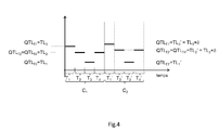
- the figure 3 illustrates a temporal evolution of the instantaneous energy level SEL stored in the PSD storage means when the means M3 of the control device GWY determines and assigns the configuration mode of the switching device COM.
- the figure 3 illustrates the evolution of the instantaneous energy level SEL for the first embodiment of the invention (where a single current load threshold is linked to each energy price and therefore to each time period).
- the current load thresholds QTL T1 , QTL T2 , QTL T3 , QTL T4 corresponding to the example treated are represented by a thick horizontal line covering the duration of a time period T 1 , T 2 , T 3 , T 4 .
- the instantaneous energy level SEL can change between the value 0 for which the PSD energy storage means is empty and the value CAP which represents the maximum capacity of the PSD means.
- the CAP capacitance of the PSD energy storage means is 100.
- the instantaneous level SEL INIT, T1 of the energy storage means PSD is known to the control device GWY as any instantaneous level SEL of energy stored in the storage means PSD. More generally, the value SEL INIT, Tj is stored in the means M2 of the control device GWY at each start of a time period T j .
- the control device GWY determines and assigns to the device COM one of the configuration modes MOD according to a comparison between an instantaneous level SEL of energy stored in the storage medium PSD and the local load threshold QTL T1 , QTL T2 , QTL T3 , QTL T4 of the current time period T 1 , T 2 , T 3, T 4 .
- the DCL client device consumes energy continuously and with a constant level over the four time periods T 1 , T 2 , T 3 , T 4 that is to say that it requires a level of energy per unit of time that is constant.
- the control device GWY and assigned to the switching device COM.
- Other hypotheses would naturally lead to the determination of other configuration modes.
- the value of the instantaneous level SEL of energy is equal to SEL INIT, T1 and is smaller than that of the local threshold of charge QTL T1 . Since the DCL client device requires power, according to the configuration mode determination logic discussed above, the GWY control device determines the second configuration mode and assigns it to the COM switch device until the instantaneous level SEL of energy reaches the value of the local threshold of charge QTL T1 . At this time, the control device GWY determines the third mode of configuration, that is to say that the operator PSO exclusively supplies the DCL client device. The PSD energy storage means is no longer powered and the instantaneous energy level SEL is constant until the end of the time period T 1 .
- the instantaneous energy level SEL decreases continuously at a speed which depends on the energy level required by the DCL device per unit of time.
- the increasing slope of the evolution of the SEL level during the first configuration mode depends on the charging speed of the PSD energy storage means.
- the control device GWY always determines and assigns the first configuration mode to the switching device COM because the instantaneous level SEL of energy, even if it decreases, remains always higher than the local load threshold levels (respectively QTL T2 over the time period T 2 and QTL T3 over the time period T 3 ): the instantaneous energy level SEL therefore decreases until the instantaneous energy level SEL reaches the local threshold value QTL T3 .
- the control device GWY determines the third mode of configuration, that is to say that the PSD energy storage means is no longer powered and the instantaneous level SEL energy is constant until at the end of the time period T 3 .
- control device GWY determines and assigns the second configuration mode to the switching device COM until the instantaneous level SEL of energy reaches the value of the local QTL T4 load threshold then it determines and assigns the third configuration mode to the COM switching device.
- the bill of energy consumption can be established as follows from the determination of the power consumption of the DCL client device and the PSD storage means:
- the first level PRL T1 , PRL T2 , PRL T3 , PRL T4 of energy consumed by the client device DCL is known to the switching device COM at the end of each time period.
- the information of the energy consumption of the client device DCL can therefore be delivered by means M1 of the control device GWY at this time.
- the energy consumption of the PSD energy storage means is also known from the switching device COM.
- the PSD energy storage means When the configuration mode assigned to the switching device COM is the first mode, the PSD energy storage means is not loaded with energy: the latter therefore consumes no energy.
- the instantaneous level SEL of energy increases which corresponds to a power consumption provided by the operator PSO.
- This energy consumption of the PSD energy storage means is illustrated by the shaded area (of triangular shape for our example) appearing under the evolution curve of the instantaneous level SEL of energy at the times when this instantaneous level SEL increases. .
- the second level PLL T1 , PLL T2 , PLL T3 , PLL T4 of energy consumed by the energy storage means PSD for is known from the switching device COM at the end of each time period.
- the information of the energy consumption of the PSD energy storage means can therefore be delivered by means M1 of the GWY control device at this time.
- PLL T1 , PLL T2 , PLL T3 , PLL T4 (5.0, 0.10) are considered.
- the switching device COM delivers to the control device GWY at the end of each time period T 1 , T 2 , T 3 , T 4 a first level PRL T1 , PRL T2 , PRL T3 , PRL T4 of energy supplied.
- at least one DCL client device during said time period T 1 , T 2 , T 3 , T 4 and a second level PLL T1 , PLL T2 , PLL T3 , PLL T4 of energy loaded in the storage means of PSD energy supplied by the PSO operator during said time period T 1 , T 2 , T 3 , T 4 .
- the 3 simulations carried out correspond to the evaluation of fictitious energy bills in situations that could have been encountered if a local threshold value of load corresponding to one of the time periods T 1 , T 2 , T 3 , T 4 differed from the QTL T1 , QTL T2 , QTL T3 , QTL Q4 local load thresholds considered in reality for the C1 time cycle.
- the GWY control device has a share of the actual cost SCR1 corresponding to the cost of the supply of energy actually invoiced and, on the other hand, 3 fictitious costs SCF1, SCF2, SCF3 corresponding to situations not encountered in reality.
- the figure 6a is a representation, corresponding to the first embodiment of the invention, the fields of use of the configuration modes, when the DCL device requires energy.
- a single QTL charge threshold T1 is associated with the price q T1 of the energy supplied by the operator PSO during the time period T1.
- the configuration mode determined by the device GWY is the second mode.
- the configuration mode determined by the GWY device is the first mode.
- the configuration mode determined by the GWY device is the third mode.
- a first difference is that the device GWY determines, in a step S2.1, a first and a second second vector V2L and V2H rather than a single second vector V2.
- the first second vector V2L has n elements (LTL 1 , ..., LTL i , ..., LTL n ) .
- the second vector V2H comprises n elements (HTL 1 , ..., HTL i ; ..., HTL n ) .
- the means M2 of the device GWY determines a first and a second current threshold (QLTL T1 , ..., QLTL Tj , ..., QLTL Tm ), (QHTL T1 ..., QHTL Tj , ..., QHTL Tm ) of charge of the PSD storage means associated with each time period T i , ..., T j , ..., T m .
- QLTL Tj is less than QHTL Tj .
- this step 2.2 aims at determining a single threshold (QTL T1 , ..., QTL Tj , ..., QTL Tm ) of charge of the PSD storage means associated with each time period.
- the means M2 of the device GWY determines a local threshold QTL Tj from a comparison between an instantaneous level SEL INIT, Tj of energy stored in the PSD storage means at the start of the time period T j and a first and a second current threshold QLTL Tj , QHTL Tj of charge of the PSD storage means associated with each time period T j .
- the figure 6b illustrates this determination of the local threshold QTL Tj .
- the first and second load thresholds (QLTL T1 , QHTL T1 where QLTL T1 ⁇ QHTL T1 ) are associated with the price of energy supplied during the period T 1 .
- the local threshold QTL T1 determined by the device GWY is the first threshold QLTL T1 load.
- the local threshold QTL T1 determined by the device GWY is the second threshold QHTL T1 load.
- the instantaneous level SEL INIT, T1 of charge is greater than or equal to QLTL T1 and less than or equal to QHTL T1 the local threshold QTL T1 determined by the device GWY is the instantaneous level SEL INIT, T1 .
- Step S3.3 is identical for the first and second embodiments of the invention.
- the DCL device requires energy over the whole period this step can lead to at most two modifications of the configuration mode: in a time period T j the device GWY can assign to the device COM successively the second mode then the third mode or the first mode then the third mode during said time period T j .
- Step S4 to evaluate a real cost SCR1 of the supply by the operator PSO of a total level SP T1 , ..., SP Tj , ..., SP Tm of energy is identical for the first and the second embodiment of the invention.
- Step S5 which relates to the evaluation of fictitious costs differs for the first and the second embodiment of the invention. The following paragraph will present these differences.
- a first difference is in the number of fictitious costs evaluated: 2n for the second embodiment and n for the first embodiment.
- the 2n fictitious costs SCLF 1 , ..., SCLF i , ..., SCLF n , SCHF 1 , ..., SCHF i , ..., SCHF n result from 2n simulations carried out by the device GWY of the cost of a supply of energy by the PSO operator to the device DCL system and PSD means.
- step S5 the means M5 simulates an operation of the means M1, M2, M3 by considering successively 2n associations (V1, V2LF2 i, V2LF2 i ), (V1, V2HF2 i , V2HF2 i ) composed of the first vector V1, and a second imaginary vector VLF2 i , VHF2 i where the second imaginary vector VLF2 i comprises n elements LTL 1 , ..., LTL i + ⁇ , ..., LTL n and the second imaginary vector VLF2 i comprises n HTL elements 1 , ..., HTL i + ⁇ , ..., HTL n , where ⁇ is a positive integer stored in the M2 means.
- This step is similar to that implemented in the first embodiment of the invention, in the second embodiment: it is implemented twice in the second embodiment to obtain the 2n fictitious costs.
- the main advantage of the various embodiments of the invention presented above is to reduce the amount of the bill of energy supply of the housing unit that is equipped with it ... while releasing its or its occupants constraints related to the time of energy consumption, that is to say, constraints related to the time of startup of household equipment.
- constraints related to the time of energy consumption that is to say, constraints related to the time of startup of household equipment.
- Embodiments of the invention comprise or essentially implement PSD energy storage means, a COM switching device and a GWY control device.
- PSD digital versatile disk
- COM COM switching device
- GWY GWY control device
- the new smart meters are adapted to provide a real-time report on the level of energy supplied to the housing unit that is equipped with it.
- the embodiment masks to the operator some of the information on the lifestyle of the occupants of the housing unit. For example, it makes it impossible to detect a human presence in an individual dwelling unit on the basis of a single piece of electrical energy supply information for the dwelling unit, since this supply of energy may be intended to to increase the charge level of the energy storage means and not to respond to the consumption of a device of the local network.
- the second embodiment of the invention is well suited to situations where the PSD energy storage means has a yield less than 100% (both for storing energy and / or for restoring it) because the existence the first and second load threshold makes it possible to favor the situation where the DCL client device is powered directly by the operator and without loss.
- it has the disadvantage of being more expensive in terms of the number of calculations since it requires 2n fictitious price evaluations and 2n price comparisons when only n fictitious price evaluations and n price comparisons are necessary for the first mode of calculation. production.
Landscapes
- Engineering & Computer Science (AREA)
- Power Engineering (AREA)
- Theoretical Computer Science (AREA)
- Transportation (AREA)
- Mechanical Engineering (AREA)
- General Physics & Mathematics (AREA)
- General Engineering & Computer Science (AREA)
- Physics & Mathematics (AREA)
- Business, Economics & Management (AREA)
- Emergency Management (AREA)
- Management, Administration, Business Operations System, And Electronic Commerce (AREA)
- Supply And Distribution Of Alternating Current (AREA)
- Charge And Discharge Circuits For Batteries Or The Like (AREA)
- Data Exchanges In Wide-Area Networks (AREA)
Priority Applications (7)
| Application Number | Priority Date | Filing Date | Title |
|---|---|---|---|
| EP20110305073 EP2479862A1 (de) | 2011-01-25 | 2011-01-25 | Verwaltung der Energiezuführung zu einem lokalen Energietransportnetz |
| KR1020137019651A KR20140003507A (ko) | 2011-01-25 | 2012-01-24 | 로컬 에너지 전달 네트워크를 위한 에너지 공급의 관리 |
| US13/980,971 US20140088785A1 (en) | 2011-01-25 | 2012-01-24 | Management of the energy supply for a local energy transport network |
| JP2013549844A JP6046054B2 (ja) | 2011-01-25 | 2012-01-24 | 局所的エネルギ輸送網のためのエネルギ供給の管理 |
| CN201280015259.2A CN103444038B (zh) | 2011-01-25 | 2012-01-24 | 本地能源传输网络的能源供应管理 |
| EP12706203.2A EP2668706A2 (de) | 2011-01-25 | 2012-01-24 | Verwaltung der energieversorgung für ein lokales stromtransportnetzwerk |
| PCT/EP2012/051028 WO2012101113A2 (fr) | 2011-01-25 | 2012-01-24 | Gestion de l'alimentation en energie d'un reseau local de transport d'energie |
Applications Claiming Priority (1)
| Application Number | Priority Date | Filing Date | Title |
|---|---|---|---|
| EP20110305073 EP2479862A1 (de) | 2011-01-25 | 2011-01-25 | Verwaltung der Energiezuführung zu einem lokalen Energietransportnetz |
Publications (1)
| Publication Number | Publication Date |
|---|---|
| EP2479862A1 true EP2479862A1 (de) | 2012-07-25 |
Family
ID=44675353
Family Applications (2)
| Application Number | Title | Priority Date | Filing Date |
|---|---|---|---|
| EP20110305073 Withdrawn EP2479862A1 (de) | 2011-01-25 | 2011-01-25 | Verwaltung der Energiezuführung zu einem lokalen Energietransportnetz |
| EP12706203.2A Withdrawn EP2668706A2 (de) | 2011-01-25 | 2012-01-24 | Verwaltung der energieversorgung für ein lokales stromtransportnetzwerk |
Family Applications After (1)
| Application Number | Title | Priority Date | Filing Date |
|---|---|---|---|
| EP12706203.2A Withdrawn EP2668706A2 (de) | 2011-01-25 | 2012-01-24 | Verwaltung der energieversorgung für ein lokales stromtransportnetzwerk |
Country Status (6)
| Country | Link |
|---|---|
| US (1) | US20140088785A1 (de) |
| EP (2) | EP2479862A1 (de) |
| JP (1) | JP6046054B2 (de) |
| KR (1) | KR20140003507A (de) |
| CN (1) | CN103444038B (de) |
| WO (1) | WO2012101113A2 (de) |
Cited By (3)
| Publication number | Priority date | Publication date | Assignee | Title |
|---|---|---|---|---|
| EP3517352A1 (de) * | 2011-06-30 | 2019-07-31 | innogy SE | Ladevorrichtung für elektrofahrzeuge und verfahren zum laden von elektrofahrzeugen |
| CN110474330A (zh) * | 2019-08-22 | 2019-11-19 | 电子科技大学 | 一种并网式混合能源系统的太阳能投资优化方法 |
| CN117638957A (zh) * | 2023-10-23 | 2024-03-01 | 国网江苏省电力有限公司南通供电分公司 | 一种基于分布式电源接入的无功优化系统方法及系统 |
Families Citing this family (2)
| Publication number | Priority date | Publication date | Assignee | Title |
|---|---|---|---|---|
| CN113500940B (zh) * | 2021-07-08 | 2022-06-28 | 东北电力大学 | 一种基于粒子群算法的电动汽车有序充放电动态优化策略 |
| CN113885511B (zh) * | 2021-10-22 | 2023-12-12 | 温州大学乐清工业研究院 | 一种断路器柔性装配机器人的轨迹优化方法 |
Citations (4)
| Publication number | Priority date | Publication date | Assignee | Title |
|---|---|---|---|---|
| EP1255340A1 (de) * | 2000-09-29 | 2002-11-06 | Matsushita Electric Industrial Co., Ltd. | Leistungsversorgungs-bedarfsregelungssystem |
| US20040263116A1 (en) * | 2003-06-30 | 2004-12-30 | Doruk Zeynep B. | Intelligent distributed energy storage system for demand side power management |
| WO2010042550A2 (en) * | 2008-10-07 | 2010-04-15 | Johnson Controls Technology Company | Efficient usage, storage, and sharing of energy in buildings, vehicles, and equipment |
| US20100306027A1 (en) * | 2009-06-02 | 2010-12-02 | International Business Machines Corporation | Net-Metering In A Power Distribution System |
Family Cites Families (10)
| Publication number | Priority date | Publication date | Assignee | Title |
|---|---|---|---|---|
| US5929538A (en) * | 1997-06-27 | 1999-07-27 | Abacus Controls Inc. | Multimode power processor |
| JP4409692B2 (ja) * | 1999-12-28 | 2010-02-03 | 三菱電機株式会社 | エレベータの制御装置 |
| KR100437004B1 (ko) * | 2001-01-17 | 2004-07-02 | 미츠비시 쥬고교 가부시키가이샤 | 스크롤형 압축기 |
| US7274975B2 (en) * | 2005-06-06 | 2007-09-25 | Gridpoint, Inc. | Optimized energy management system |
| JP2007166818A (ja) * | 2005-12-15 | 2007-06-28 | Sharp Corp | 電源システムおよびその制御方法 |
| US7590472B2 (en) * | 2006-11-09 | 2009-09-15 | Gridpoint, Inc. | Energy arbitrage by load shifting |
| US8872379B2 (en) * | 2007-11-30 | 2014-10-28 | Johnson Controls Technology Company | Efficient usage, storage, and sharing of energy in buildings, vehicles, and equipment |
| JP5465949B2 (ja) * | 2009-08-07 | 2014-04-09 | 本田技研工業株式会社 | 電力供給システム |
| JP5520574B2 (ja) * | 2009-11-06 | 2014-06-11 | パナソニック株式会社 | 電力融通システム |
| US20110125337A1 (en) * | 2010-08-30 | 2011-05-26 | Vyacheslav Zavadsky | Household appliance adapted to work with time of use electricity rates |
-
2011
- 2011-01-25 EP EP20110305073 patent/EP2479862A1/de not_active Withdrawn
-
2012
- 2012-01-24 CN CN201280015259.2A patent/CN103444038B/zh not_active Expired - Fee Related
- 2012-01-24 JP JP2013549844A patent/JP6046054B2/ja not_active Expired - Fee Related
- 2012-01-24 WO PCT/EP2012/051028 patent/WO2012101113A2/fr not_active Ceased
- 2012-01-24 EP EP12706203.2A patent/EP2668706A2/de not_active Withdrawn
- 2012-01-24 KR KR1020137019651A patent/KR20140003507A/ko not_active Withdrawn
- 2012-01-24 US US13/980,971 patent/US20140088785A1/en not_active Abandoned
Patent Citations (4)
| Publication number | Priority date | Publication date | Assignee | Title |
|---|---|---|---|---|
| EP1255340A1 (de) * | 2000-09-29 | 2002-11-06 | Matsushita Electric Industrial Co., Ltd. | Leistungsversorgungs-bedarfsregelungssystem |
| US20040263116A1 (en) * | 2003-06-30 | 2004-12-30 | Doruk Zeynep B. | Intelligent distributed energy storage system for demand side power management |
| WO2010042550A2 (en) * | 2008-10-07 | 2010-04-15 | Johnson Controls Technology Company | Efficient usage, storage, and sharing of energy in buildings, vehicles, and equipment |
| US20100306027A1 (en) * | 2009-06-02 | 2010-12-02 | International Business Machines Corporation | Net-Metering In A Power Distribution System |
Cited By (5)
| Publication number | Priority date | Publication date | Assignee | Title |
|---|---|---|---|---|
| EP3517352A1 (de) * | 2011-06-30 | 2019-07-31 | innogy SE | Ladevorrichtung für elektrofahrzeuge und verfahren zum laden von elektrofahrzeugen |
| CN110474330A (zh) * | 2019-08-22 | 2019-11-19 | 电子科技大学 | 一种并网式混合能源系统的太阳能投资优化方法 |
| CN110474330B (zh) * | 2019-08-22 | 2023-04-18 | 电子科技大学 | 一种并网式混合能源系统的太阳能投资优化方法 |
| CN117638957A (zh) * | 2023-10-23 | 2024-03-01 | 国网江苏省电力有限公司南通供电分公司 | 一种基于分布式电源接入的无功优化系统方法及系统 |
| CN117638957B (zh) * | 2023-10-23 | 2024-07-16 | 国网江苏省电力有限公司南通供电分公司 | 一种基于分布式电源接入的无功优化系统方法及系统 |
Also Published As
| Publication number | Publication date |
|---|---|
| WO2012101113A3 (fr) | 2013-04-11 |
| CN103444038A (zh) | 2013-12-11 |
| US20140088785A1 (en) | 2014-03-27 |
| EP2668706A2 (de) | 2013-12-04 |
| JP6046054B2 (ja) | 2016-12-14 |
| KR20140003507A (ko) | 2014-01-09 |
| JP2014504845A (ja) | 2014-02-24 |
| WO2012101113A2 (fr) | 2012-08-02 |
| CN103444038B (zh) | 2016-08-17 |
Similar Documents
| Publication | Publication Date | Title |
|---|---|---|
| FR2973963A1 (fr) | Dispositif de transfert de charge et procede de gestion associe | |
| EP2479862A1 (de) | Verwaltung der Energiezuführung zu einem lokalen Energietransportnetz | |
| EP2753491B1 (de) | Verfahren und vorrichtung zum optimierten wiederaufladen einer elektrischen batterie | |
| EP3672019B1 (de) | Steuerverfahren und -vorrichtung des auf- und entladens von batterien einer anordnung solcher batterien mit teilweiser aufladung einer batterie | |
| EP3240277A1 (de) | Kontrollverfahren der elektrischen energieströme innerhalb eines funkzugriffssystems auf ein kommunikationsnetz, und entsprechende kontrollvorrichtung | |
| EP2892753A2 (de) | Wiederaufladung einer gruppe von batterien | |
| WO2012126855A2 (fr) | Gestion centralisee de l'alimentation en energie d'une pluralite de reseaux locaux d'energie | |
| FR2944162A1 (fr) | Systeme d'alimentation electrique et procede de controle de charge de generateurs electrochimiques | |
| FR3067878B1 (fr) | Procede de charge de batteries pour un aeronef et systeme de stockage d'energie electrique | |
| FR3105864A1 (fr) | Procédé de gestion automatique d’un flux d’énergie électrique | |
| EP3394923A1 (de) | System und verfahren zur steuerung einer stromspeichervorrichtung | |
| WO2020089543A1 (fr) | Dispositif de recharge rapide de vehicules electriques via des vehicules electriques de location | |
| EP4367843A1 (de) | Verfahren zur verwaltung des stromverbrauchs von geräten in einem lokalen kommunikationsnetz, entsprechende verwaltungsvorrichtung und computerprogramm | |
| FR3072794A1 (fr) | Procede de determination des parametres d'un modele simplifie d'un systeme de stockage de l'energie, procede de pilotage utilisant un tel modele et dispositif associe | |
| EP3996226A1 (de) | Verfahren und systeme für die automatische konfiguration eines elektrischen mikronetzes | |
| FR3028987A1 (fr) | Procede et systeme de gestion de la charge d'un parc de batteries | |
| FR3122795A3 (fr) | Installation de surveillance et système de surveillance pour surveiller et/ou contrôler au moins un paramètre électrique dans un système d’alimentation électrique, et programme informatique | |
| EP4175160B1 (de) | Optimierung der verwendung einer elektrogengruppe | |
| FR3060819A1 (fr) | Coordination de gestion de consommation d'energie electrique | |
| EP2533391B1 (de) | Multi-Source-Steuerungssystem von Stromgeneratoren | |
| FR3012646A1 (fr) | Procede d'optimisation de la consommation et de la production d'une installation electrique | |
| FR3102873A1 (fr) | Procédé de désagrégation d’une courbe de charge électrique | |
| EP3979163B1 (de) | Optimierung der in einem mini-netz verfügbaren energie | |
| FR3157710A1 (fr) | Procédé amélioré de pilotage multi-niveaux par bandeaux d’un réseau électrique ; Programme d’ordinateur associé. | |
| FR2991823A1 (fr) | Dispositif et procede de repartition de la puissance electrique issue de differentes sources d'electricite |
Legal Events
| Date | Code | Title | Description |
|---|---|---|---|
| PUAI | Public reference made under article 153(3) epc to a published international application that has entered the european phase |
Free format text: ORIGINAL CODE: 0009012 |
|
| AK | Designated contracting states |
Kind code of ref document: A1 Designated state(s): AL AT BE BG CH CY CZ DE DK EE ES FI FR GB GR HR HU IE IS IT LI LT LU LV MC MK MT NL NO PL PT RO RS SE SI SK SM TR |
|
| AX | Request for extension of the european patent |
Extension state: BA ME |
|
| STAA | Information on the status of an ep patent application or granted ep patent |
Free format text: STATUS: THE APPLICATION IS DEEMED TO BE WITHDRAWN |
|
| 18D | Application deemed to be withdrawn |
Effective date: 20130126 |