EP2479885B1 - Durchflussabbruch in einem Dauermagnetgenerator - Google Patents
Durchflussabbruch in einem Dauermagnetgenerator Download PDFInfo
- Publication number
- EP2479885B1 EP2479885B1 EP11193735.5A EP11193735A EP2479885B1 EP 2479885 B1 EP2479885 B1 EP 2479885B1 EP 11193735 A EP11193735 A EP 11193735A EP 2479885 B1 EP2479885 B1 EP 2479885B1
- Authority
- EP
- European Patent Office
- Prior art keywords
- permanent magnet
- winding
- primary
- output terminal
- generator
- Prior art date
- Legal status (The legal status is an assumption and is not a legal conclusion. Google has not performed a legal analysis and makes no representation as to the accuracy of the status listed.)
- Not-in-force
Links
Images


Classifications
-
- H—ELECTRICITY
- H02—GENERATION; CONVERSION OR DISTRIBUTION OF ELECTRIC POWER
- H02K—DYNAMO-ELECTRIC MACHINES
- H02K3/00—Details of windings
- H02K3/04—Windings characterised by the conductor shape, form or construction, e.g. with bar conductors
- H02K3/28—Layout of windings or of connections between windings
-
- H—ELECTRICITY
- H02—GENERATION; CONVERSION OR DISTRIBUTION OF ELECTRIC POWER
- H02P—CONTROL OR REGULATION OF ELECTRIC MOTORS, ELECTRIC GENERATORS OR DYNAMO-ELECTRIC CONVERTERS; CONTROLLING TRANSFORMERS, REACTORS OR CHOKE COILS
- H02P25/00—Arrangements or methods for the control of AC motors characterised by the kind of AC motor or by structural details
- H02P25/16—Arrangements or methods for the control of AC motors characterised by the kind of AC motor or by structural details characterised by the circuit arrangement or by the kind of wiring
- H02P25/18—Arrangements or methods for the control of AC motors characterised by the kind of AC motor or by structural details characterised by the circuit arrangement or by the kind of wiring with arrangements for switching the windings, e.g. with mechanical switches or relays
Definitions
- the present invention relates generally to permanent magnet generators, and more particularly to methods and apparatus for de-energizing permanent magnet generators.
- Electromagnetic generators convert mechanical energy into electricity by producing changing magnetic flux from mechanical movement. Changes in magnetic flux through windings of wire induce voltage in these windings according to Faraday's law, producing deliverable electric energy.
- Permanent magnet generators (PMGs) produce varying flux through generator windings either with permanent magnet rotors, or with permanent magnet stators. Generators with permanent magnet rotors drive rotating permanent magnets to produce magnetic fields that vary at fixed stator winding locations. Generators with permanent magnet stators use stationary magnets to produce magnetic fields through which rotor windings travel, for the same ultimate effect.
- PMGs will hereafter be assumed to use permanent magnet rotors, although those skilled in the art will understand that generators can analogously be constructed with stationary magnets and rotating windings.
- Rotating magnets produce varying magnetic flux governed by the right-hand-rule. Whenever net flux passing through stator windings varies, this induces currents tending to oppose the change in flux. As a result, a PMG will ordinarily continue to produce voltage as long as the permanent magnet rotor turns.
- a variety of techniques have been developed to de-energize PMGs.
- a PMG can be dc-energized by mechanically halting rotor movement, but this method is slow, and usually necessitates decoupling the generator drive shaft from its mechanical power source.
- some systems include specialized stator windings attached to an external power supply. When rapid flux cancellation is needed, these systems force current through the specialized stator windings to produce a countervailing magnetic flux, canceling changes in flux generated by the rotating permanent magnets.
- Another system ( US 7,777,384 ) provides conductive shunts which route flux away from stator windings, thereby preventing currents from being induced on stator windings.
- PMGs are preferably capable of rapidly de-energizing without sacrificing normal operational power.
- existing mechanisms for de-energizing PMGs add considerable bulk or complexity. Simpler, smaller mechanisms are highly desirable.
- the present invention is directed toward permanent magnet generators having a primary winding, a secondary winding, a permanent magnet, an output terminal for connection to an external load, and a switching mechanism with two modes.
- the primary winding In a first mode of the switching mechanism, the primary winding is connected between neutral and the output terminal, and the varying magnetic flux from the permanent magnet induces a nonzero current and voltage at the output terminal.
- the secondary winding In the second mode, the secondary winding provides a return path to neutral for the primary winding, thereby providing negligible voltage or current at the output terminal and substantially canceling change in magnetic flux from the permanent magnet.
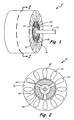
- FIG. 1 is a perspective view of a section of a permanent magnet generator.
- FIG. 2 is a cross-sectional view of the permanent magnet generator of FIG. 1 , illustrating a permanent magnet rotor and a stator with stator windings.
- FIG. 3A is a schematic view of one phase of the rotor and stator of FIG. 1 .
- FIG. 3B is a simplified schematic view of the stator configuration of FIG. 3A .
- FIG. 4A is a simplified schematic view of an alternative stator configuration.
- FIG. 4B is a simplified schematic view of the normal operation mode of the stator configuration of FIG. 4A .
- FIG. 4C is a simplified schematic view of the cancellation mode of the stator configuration of FIG. 4A .
- FIG. 1 is a perspective view of permanent magnet generator 10, including drive shaft 12, rotor 14 (with permanent magnets 20), stator 16 (with stator coil 22), and air gap 18.
- Drive shaft 12 is rotatable by an energy source (not shown) such as rotational motion of a vehicle drive system, wind, water, or another prime mover.
- Drive shaft 12 turns rotor 14, which contains cylindrically arranged permanent magnets 20.
- Stator 16, which surrounds rotor 14, contains multiple stator coils 22, each with multiple windings.
- Stator coils 22 are dense coils of looping conductive wire.
- Rotor 14 is separated from stator 16 by air gap 18, a narrow open space. It will be understood by one skilled in the art that, although this description focuses on generators having permanent magnet rotors, the invention could analogously be constructed with a permanent magnet stator and multiple rotor coils.
- FIG. 2 is a cross-section of permanent magnet generator 10 along cross-section line 2-2 from FIG. 1.
- FIG. 2 depicts generator 10, including drive shaft 12, rotor 14 (with permanent magnets 20), stator 16 (with stator coils 22), and air gap 18.
- Permanent magnets 20 are anchored to rotor 14, and stator coils 22 are anchored to stator 16.
- Magnetic fields from permanent magnet 20 cross air gap 18 and pass through stator coils 22 with magnetic flux ⁇ pm (not shown in FIG. 2 ; see FIG. 3 ).
- ⁇ pm not shown in FIG. 2 ; see FIG. 3
- As drive shaft 12 rotates rotor 14 the movement of permanent magnets 20 causes ⁇ pm to vary, causing a voltage to develop across stator coils 22.
- Electromotive force ⁇ induces a current I stator in stator coils 22, which can be coupled to an external load to supply power.
- FIG. 3A is a schematic view of permanent magnet generator 10 illustrating a stator coil configuration of the present invention.
- FIG. 3A illustrates rotor 14 (with permanent magnet 20), stator 16 (with stator coils 22), magnetic flux ⁇ pm , magnetic flux ⁇ c , switching contact S, switch control 24, neutral N, and output terminal T out with output voltage V.
- Stator coils 22 comprise primary windings 22a (with current I pri ) and secondary windings 22b (with current I sec ).
- Every set of primary windings 22a in stator coil 22 is uniquely paired with a set of secondary windings 22b.
- Primary windings 22a and secondary windings 22b have an identical number of turns.
- Primary windings 22a extend from neutral post N to output terminal T out
- secondary windings 22b and switching contactor S form a cancellation circuit between neutral post N and output terminal T out .
- secondary windings 22b extend from switching contactor S to neutral post N.
- switching contactor S could be located between secondary windings 22b and neutral post N
- secondary windings 22b could extend between output terminal T out and switching contactor S.
- switching contactor S The opening and closing of switching contactor S is controlled by switch control 24.
- Switching contactor S is open during normal generator operation, and disconnects secondary windings 22b so that I sec is zero.
- current I pri is supplied to output terminal T out .
- V the voltage at output terminal T out , is nonzero value so long as rotor 14 continues to turn.
- Current I pri tends to oppose change in flux ⁇ pm , according to Lenz's law (as does I sec , when present), producing a countervailing flux ⁇ c . Because of load current limiting, change in ⁇ c will always be less than change in ⁇ pm , and will never fully cancel change in ⁇ pm .
- FIG. 3B is a simplified schematic view of stator coil 22 of FIG. 3A , showing only one phase of primary windings 22a, secondary windings 22b, neutral post N, output terminal T out , switching contact S, and switch control 24.
- Switching contact S is an electrical switch capable of connecting or isolating secondary windings 22b, and is open during normal operation of PMG 10.
- Switch control 24 actuates switching contact S.
- switch control 24 opens and closes switching contact S in response to operator input.
- switch control 24 may open and close switching contact S automatically in response to sensed PMG conditions, Switch control may automatically close switching contact S in response, for instance, to detection of a harmful generator fault, thereby immediately de-energizing PMG 10 to avoid damage.
- switching contactor S is open, primary windings 22a generate power, and secondary windings 22b are electrically isolated.
- switching contactor S is closed, and primary windings 22a are shorted through secondary windings 22b, as previously discussed with respect to FIG. 3A .
- FIG. 4A is a simplified schematic view of an alternative circuit configuration for stator coil 22.
- FIG. 4A illustrates primary windings 22a, secondary windings 22b, neutral post N, output terminal T out , voltage V, and switching contactors S 1A , S 1B , S 2A , and S 2B .
- FIGs. 4B and 4C are simplified schematic views of states of the circuit configuration of FIG. 4A , illustrating primary windings 22a, secondary windings 22b, neutral post N, output terminal T out , and voltage V.
- FIG. 4B illustrates a normal operation mode
- FIG. 4C illustrates a cancellation mode.
- Switching contactors S 1A , S 1B , S 2A , and S 2B are contactors like switching contactor S.
- FIGs. 3A and 3B During normal operation, the circuit configuration of FIGs. 3A and 3B only utilizes primary windings 22a to generate power, leaving secondary winding 22b disconnected.
- the alternative configuration illustrated in FIG. 4A enables the entirety of stator coil 22 -- both primary windings 22a and secondary windings 22b - to be utilized for power generation, but requires slightly more sophisticated wiring.
- switching contactors S 1A and S 1B are closed, and switching contactors S 2A and S 2B are open, such that primary windings 22a and secondary windings 22b operate in parallel, as indicated by FIG. 4B .
- This configuration doubles the utilized copper area of the winding, and therefore reduces copper power loss relative to the configuration of FIGs. 3A and 3B .
- switches are reversed: switching contactors S 2A and S 2B are closed, and switching contactors S 1A and S 1B are open. In this mode, primary windings 22a are shorted through secondary windings 22b, as discussed previously.
- the present invention offers a mechanism for substantially canceling flux through stator coil 22 without halting permanent magnet rotor 14, and with little additional manufacturing complexity. No external power source is required for flux cancellation, and the additional wiring needed for cancellation is minimal.
- the only moving parts used by this cancellation system are switching contactors, which are simple, small, and well-known in the art. As disclosed in the embodiment of FIGs. 4A through 4C , all windings of stator coils 22 are used during normal operation.
Landscapes
- Engineering & Computer Science (AREA)
- Power Engineering (AREA)
- Control Of Eletrric Generators (AREA)
- Windings For Motors And Generators (AREA)
Claims (14)
- Permanentmagnetgenerator, aufweisend:mindestens einen Permanentmagnet (20);einen Ausgangsanschluss (Tout) zur Verbindung mit einer elektrischen Last;eine primäre Wicklung (22a), durch welche der mindestens eine Permanentmagnet einen veränderlichen magnetischen Fluss erzeugt, wobei die primäre Wicklung zwischen einem Neutralanschluss und dem Ausgangsanschluss angeschlossen ist; undeine Ausgleichsschaltung, die zwischen dem Ausgangsanschluss und dem Neutralanschluss angeschlossen ist, wobei die Ausgleichsschaltung eine sekundäre Wicklung (22b), durch welche der mindestens eine Permanentmagnet einen veränderlichen magnetischen Fluss erzeugt, und einen Schaltmechanismus (S, 24) aufweist, welcher aufweist:einen ersten Schaltzustand, in dem die Ausgleichsschaltung keinen Strompfad für die primäre Wicklung bereitstellt und in dem eine Veränderung des magnetischen Flusses durch die primäre Wicklung einen Strom durch die primäre Wicklung induziert, welcher eine Spannung ungleich Null an dem Ausgangsanschluss erzeugt; undeinen zweiten Schaltzustand, in dem die sekundäre Wicklung einen Rückflusspfad zum Neutralanschluss für die primäre Wicklung bereitstellt, wodurch eine vernachlässigbare Spannung oder ein vernachlässigbarer Strom an dem Ausgangsanschluss bereitgestellt wird und eine Änderung des Flusses durch die primäre Wicklung und die sekundäre Wicklung im Wesentlichen ausgeglichen wird, wodurch der Permanentmagnetgenerator im Wesentlichen energiefrei gemacht wird, um den Permanentmagnetgenerator in einem Fehlerzustand zu schützen.
- Permanentmagnetgenerator nach Anspruch 1, wobei der Schaltmechanismus manuell von einem Bediener gesteuert ist oder wobei der Schaltmechanismus automatisch als Reaktion auf einen Fehlerzustand von dem ersten Schaltzustand in den zweiten Schaltzustand schaltet.
- Permanentmagnetgenerator nach Anspruch 1 oder 2, wobei kein Strom durch die sekundäre Wicklung in dem ersten Schaltzustand fließt.
- Permanentmagnetgenerator nach Anspruch 1, 2 oder 3, wobei:der erste Schaltzustand die sekundäre Wicklung parallel zu der primären Wicklung mit dem Ausgangsanschluss und dem Neutralanschluss verbindet; undeine Änderung des magnetischen Flusses durch die sekundäre Wicklung einen Strom in der sekundären Wicklung induziert, wodurch eine Spannung ungleich Null an dem Ausgangsanschluss erzeugt wird.
- Permanentmagnetgenerator nach einem der vorhergehenden Ansprüche, wobei die primäre Wicklung und die sekundäre Wicklung eine identischen Anzahl von Windungen haben.
- Permanentmagnetgenerator nach einem der vorhergehenden Ansprüche, weiterhin aufweisend eine Stator (16) und eine Rotor (14), wobei die primäre Wicklung und die sekundäre Wicklung an dem Stator angeordnet sind und der mindestens eine Permanentmagnet an dem Rotor angeordnet ist.
- Permanentmagnetgenerator, aufweisend:einen Ausgangsanschluss zur Verbindung mit einer elektrischen Last;einen Permanentmagnetrotor (14), der einen magnetischen Fluss erzeugt;eine primäre Statorwicklung (22a), in welcher eine Änderung des magnetischen Flusses einen ersten Strom induzieren kann, welcher der Änderung des magnetischen Flusses entgegenwirkt;eine sekundäre Statorwicklung (22b), in welcher eine Änderung des magnetischen Flusses einen zweiten Strom induzieren kann, welcher der Änderung des magnetischen Flusses entgegenwirkt; undeinen Schaltmechanismus (S, 24), welcher aufweist:einen ersten Schaltzustand, wobei die primäre Statorwicklung Strom und Spannung an dem Ausgangsanschluss liefert; undeinen zweiten Schaltzustand, wobei die primäre Statorwicklung mit der sekundären Statorwicklung elektrisch verbunden ist, um für die primäre Statorwicklung einen Rückflusspfad zum Neutralanschluss bereitzustellen, wodurch der erste Strom und der zweite Strom ausgeglichen werden, welche zusammen einen magnetischen Fluss erzeugen, der im Wesentlichen die Änderung des magnetischen Flusses ausgleicht, wodurch der Permanentmagnetgenerator im Wesentlich energiefrei gemacht wird, um den Permanentmagnetgenerator in einem Fehlerzustand zu schützen.
- Permanentmagnetgenerator nach Anspruch 7, wobei der Schaltmechanismus Zustände als Reaktion auf Bediener-Befehle schaltet oder wobei der Schaltmechanismus automatisch Zustände auf die Detektion eines Generatorfehlers hin schaltet.
- Permanentmagnetgenerator nach Anspruch 7 oder 8, wobei die sekundäre Statorwicklung in dem ersten Schaltzustand auch Strom und Spannung an dem Ausgangsanschluss bereitstellt.
- Permanentmagnetgenerator nach Anspruch 7, 8 oder 9, wobei die sekundäre Statorwicklung in dem ersten Schaltzustand isoliert ist und der zweite Strom dementsprechend in dem ersten Schaltzustand Null ist, unabhängig von der Bewegung des Permanentmagnetrotors.
- Permanentmagnetgenerator nach einem der Ansprüche 7 bis 10, wobei die primäre Statorwicklung und die sekundäre Statorwicklung eine identische Anzahl von Windungen haben.
- Permanentmagnetgenerator, aufweisend:einen Ausgangsanschluss (Tout) zur Verbindung mit einer externen Last;eine primäre Wicklung (22a), die zwischen einem Neutralanschluss und dem Ausgangsanschluss angeschlossen ist;mindestens einen Permanentmagneten (20), der in der Lage ist, einen sich ändernden magnetischen Fluss durch die primäre Wicklung zu erzeugen, wodurch ein erster Strom in der primären Wicklung induziert wird, der der Änderung des Flusses entgegenwirkt; undeine sekundäre Wicklung (226), die wahlweise mit der primären Wicklung elektrisch verbindbar ist, um einen Rückflusspfad zum Neutralanschluss für die primäre Wicklung bereitzustellen, so dass keine Spannung oder kein Strom an die externe Last bereitgestellt wird, wenn die sekundäre Wicklung mit der primären Wicklung verbunden ist, wodurch der Permanentmagnetgenerator im Wesentlichen energiefrei gemacht wird, um den Permanentmagnetgenerator in einem Fehlerzustand zu schützen.
- Permanentmagnetgenerator nach Anspruch 12, wobei die primäre Wicklung und die sekundäre Wicklung eine identische Anzahl von Windungen haben.
- Permanentmagnetgenerator nach Anspruch 12 oder 13, wobei ein Kurzschließen der primären Generatorwicklung dazu führt, dass ein Strom von dem Permanentmagnet in der primären Wicklung und der sekundäre Wicklung induziert wird, der im Wesentlichen vollständig die Änderungen des sich ändernden magnetischen Flusses ausgleicht.
Applications Claiming Priority (1)
| Application Number | Priority Date | Filing Date | Title |
|---|---|---|---|
| US13/009,435 US8278858B2 (en) | 2011-01-19 | 2011-01-19 | Flux cancellation in a permanent magnet generator |
Publications (2)
| Publication Number | Publication Date |
|---|---|
| EP2479885A1 EP2479885A1 (de) | 2012-07-25 |
| EP2479885B1 true EP2479885B1 (de) | 2013-10-02 |
Family
ID=45491247
Family Applications (1)
| Application Number | Title | Priority Date | Filing Date |
|---|---|---|---|
| EP11193735.5A Not-in-force EP2479885B1 (de) | 2011-01-19 | 2011-12-15 | Durchflussabbruch in einem Dauermagnetgenerator |
Country Status (4)
| Country | Link |
|---|---|
| US (1) | US8278858B2 (de) |
| EP (1) | EP2479885B1 (de) |
| KR (1) | KR20120084260A (de) |
| CN (1) | CN102611267A (de) |
Cited By (1)
| Publication number | Priority date | Publication date | Assignee | Title |
|---|---|---|---|---|
| US10680474B2 (en) | 2017-11-08 | 2020-06-09 | Rolls-Royce Plc | Permanent magnet electrical machine |
Families Citing this family (6)
| Publication number | Priority date | Publication date | Assignee | Title |
|---|---|---|---|---|
| US11482360B2 (en) * | 2017-12-12 | 2022-10-25 | The Boeing Company | Stator secondary windings to modify a permanent magnet (PM) field |
| KR101964069B1 (ko) * | 2017-12-20 | 2019-04-02 | (주)바롬코리아 | 구동토크가 개선된 다단발전기 |
| WO2019157626A1 (en) * | 2018-02-13 | 2019-08-22 | Envision Energy (Jiangsu) Co., Ltd. | Demagnetization protection of a permanent magnet generator |
| US20210249981A1 (en) | 2018-09-05 | 2021-08-12 | Dpm Technologies Inc. | Systems and methods for intelligent control of rotating electric machines |
| CN117337545A (zh) | 2021-05-13 | 2024-01-02 | Exro技术公司 | 驱动多相电机的线圈的方法及装置 |
| KR20240046176A (ko) | 2021-07-08 | 2024-04-08 | 엑스로 테크놀로지스 아이엔씨. | 전기 기계의 와인딩들을 이용한 동적으로 재구성가능한 전력 변환기 |
Citations (1)
| Publication number | Priority date | Publication date | Assignee | Title |
|---|---|---|---|---|
| US4336486A (en) * | 1980-01-09 | 1982-06-22 | Westinghouse Electric Corp. | Dynamoelectric machines brushless supplemental excitation system |
Family Cites Families (4)
| Publication number | Priority date | Publication date | Assignee | Title |
|---|---|---|---|---|
| JPS5438115A (en) * | 1977-08-31 | 1979-03-22 | Canon Inc | Control system for energizing dynamo built-in camera |
| US7253548B2 (en) | 2003-06-16 | 2007-08-07 | Pratt & Whitney Canada Corp. | Method and apparatus for controlling an electric machine |
| DE102007040725A1 (de) | 2007-08-29 | 2009-03-05 | Robert Bosch Gmbh | Elektrische Maschine |
| US7777384B2 (en) | 2008-04-02 | 2010-08-17 | Hamilton Sundstrand Corporation | Permanent magnet dynamoelectric machine with variable magnetic flux excitation |
-
2011
- 2011-01-19 US US13/009,435 patent/US8278858B2/en not_active Expired - Fee Related
- 2011-12-15 EP EP11193735.5A patent/EP2479885B1/de not_active Not-in-force
-
2012
- 2012-01-12 KR KR1020120003780A patent/KR20120084260A/ko not_active Withdrawn
- 2012-01-19 CN CN2012100170696A patent/CN102611267A/zh active Pending
Patent Citations (1)
| Publication number | Priority date | Publication date | Assignee | Title |
|---|---|---|---|---|
| US4336486A (en) * | 1980-01-09 | 1982-06-22 | Westinghouse Electric Corp. | Dynamoelectric machines brushless supplemental excitation system |
Cited By (1)
| Publication number | Priority date | Publication date | Assignee | Title |
|---|---|---|---|---|
| US10680474B2 (en) | 2017-11-08 | 2020-06-09 | Rolls-Royce Plc | Permanent magnet electrical machine |
Also Published As
| Publication number | Publication date |
|---|---|
| KR20120084260A (ko) | 2012-07-27 |
| US8278858B2 (en) | 2012-10-02 |
| EP2479885A1 (de) | 2012-07-25 |
| CN102611267A (zh) | 2012-07-25 |
| US20120181892A1 (en) | 2012-07-19 |
Similar Documents
| Publication | Publication Date | Title |
|---|---|---|
| EP2479885B1 (de) | Durchflussabbruch in einem Dauermagnetgenerator | |
| US6909263B2 (en) | Gas turbine engine starter-generator exciter starting system and method including a capacitance circuit element | |
| RU2410823C2 (ru) | Двигатель с поперечным потоком и турбодвигатель с двигателем с поперечным потоком такого рода | |
| RU2346374C1 (ru) | Электродвигатель-генератор переменного тока (варианты) и генератор переменного тока (варианты) | |
| US7388311B2 (en) | Redundant windings with current limiting means for electric machines | |
| US9543876B2 (en) | Three phase flux switching generator in a three stage wound field synchronous machine | |
| JP2009540776A5 (de) | ||
| EP2779421B1 (de) | Integrierter Startergenerator | |
| US20200244127A1 (en) | Stator winding for a rotating electrical machine | |
| US8035357B2 (en) | Fault clearing for permanent magnet machines | |
| KR20130028919A (ko) | 전기 기기의 보호 회로 및 보호 방법 | |
| US9257877B2 (en) | Superconducting machine and method for the operation thereof | |
| RU2504066C2 (ru) | Система электрического питания для трехфазного двигателя с постоянными магнитами | |
| US3202875A (en) | Protective relay system | |
| Ruiqing et al. | The balanced current control of dual-redundancy permanent magnetic brushless DC motor | |
| US20210234445A1 (en) | Electric machine and hybrid electric aircraft | |
| RU2691735C1 (ru) | Устройство защиты от короткого замыкания магнитоэлектрического генератора | |
| RU2788965C1 (ru) | Бесщеточный синхронный генератор с усовершенствованным управлением в аварийном режиме | |
| RU2634836C1 (ru) | Устройство защиты от короткого замыкания высокотемпературного стартер-генератора обращённой конструкции | |
| US520764A (en) | Louis bell | |
| US12081015B2 (en) | Permanent magnet machine fault protection | |
| US10870434B1 (en) | Vehicle inspection system | |
| BR102013014538A2 (pt) | Máquina elétrica dc tipo comutador intertravado cruzado que possui anel e escova de condução e enrolamento de excitação auxiliar | |
| EP2104224B1 (de) | Fehlerbehebungsverfahren für Permanentmagnetmaschinen | |
| SU1597947A1 (ru) | Устройство дл коммутации цепей переменного и посто нного тока |
Legal Events
| Date | Code | Title | Description |
|---|---|---|---|
| PUAI | Public reference made under article 153(3) epc to a published international application that has entered the european phase |
Free format text: ORIGINAL CODE: 0009012 |
|
| AK | Designated contracting states |
Kind code of ref document: A1 Designated state(s): AL AT BE BG CH CY CZ DE DK EE ES FI FR GB GR HR HU IE IS IT LI LT LU LV MC MK MT NL NO PL PT RO RS SE SI SK SM TR |
|
| AX | Request for extension of the european patent |
Extension state: BA ME |
|
| 17P | Request for examination filed |
Effective date: 20130125 |
|
| RIC1 | Information provided on ipc code assigned before grant |
Ipc: H02P 25/18 20060101AFI20130325BHEP Ipc: H02P 9/10 20060101ALI20130325BHEP Ipc: H02P 9/12 20060101ALI20130325BHEP |
|
| GRAP | Despatch of communication of intention to grant a patent |
Free format text: ORIGINAL CODE: EPIDOSNIGR1 |
|
| INTG | Intention to grant announced |
Effective date: 20130507 |
|
| GRAS | Grant fee paid |
Free format text: ORIGINAL CODE: EPIDOSNIGR3 |
|
| GRAA | (expected) grant |
Free format text: ORIGINAL CODE: 0009210 |
|
| AK | Designated contracting states |
Kind code of ref document: B1 Designated state(s): AL AT BE BG CH CY CZ DE DK EE ES FI FR GB GR HR HU IE IS IT LI LT LU LV MC MK MT NL NO PL PT RO RS SE SI SK SM TR |
|
| REG | Reference to a national code |
Ref country code: GB Ref legal event code: FG4D |
|
| REG | Reference to a national code |
Ref country code: CH Ref legal event code: EP Ref country code: AT Ref legal event code: REF Ref document number: 635042 Country of ref document: AT Kind code of ref document: T Effective date: 20131015 |
|
| REG | Reference to a national code |
Ref country code: IE Ref legal event code: FG4D |
|
| REG | Reference to a national code |
Ref country code: DE Ref legal event code: R096 Ref document number: 602011003266 Country of ref document: DE Effective date: 20131205 |
|
| REG | Reference to a national code |
Ref country code: AT Ref legal event code: MK05 Ref document number: 635042 Country of ref document: AT Kind code of ref document: T Effective date: 20131002 |
|
| REG | Reference to a national code |
Ref country code: NL Ref legal event code: VDEP Effective date: 20131002 |
|
| PG25 | Lapsed in a contracting state [announced via postgrant information from national office to epo] |
Ref country code: SI Free format text: LAPSE BECAUSE OF FAILURE TO SUBMIT A TRANSLATION OF THE DESCRIPTION OR TO PAY THE FEE WITHIN THE PRESCRIBED TIME-LIMIT Effective date: 20131002 |
|
| REG | Reference to a national code |
Ref country code: LT Ref legal event code: MG4D |
|
| PG25 | Lapsed in a contracting state [announced via postgrant information from national office to epo] |
Ref country code: BE Free format text: LAPSE BECAUSE OF FAILURE TO SUBMIT A TRANSLATION OF THE DESCRIPTION OR TO PAY THE FEE WITHIN THE PRESCRIBED TIME-LIMIT Effective date: 20131002 Ref country code: FI Free format text: LAPSE BECAUSE OF FAILURE TO SUBMIT A TRANSLATION OF THE DESCRIPTION OR TO PAY THE FEE WITHIN THE PRESCRIBED TIME-LIMIT Effective date: 20131002 Ref country code: NO Free format text: LAPSE BECAUSE OF FAILURE TO SUBMIT A TRANSLATION OF THE DESCRIPTION OR TO PAY THE FEE WITHIN THE PRESCRIBED TIME-LIMIT Effective date: 20140102 Ref country code: IS Free format text: LAPSE BECAUSE OF FAILURE TO SUBMIT A TRANSLATION OF THE DESCRIPTION OR TO PAY THE FEE WITHIN THE PRESCRIBED TIME-LIMIT Effective date: 20140202 Ref country code: CZ Free format text: LAPSE BECAUSE OF FAILURE TO SUBMIT A TRANSLATION OF THE DESCRIPTION OR TO PAY THE FEE WITHIN THE PRESCRIBED TIME-LIMIT Effective date: 20131002 Ref country code: HR Free format text: LAPSE BECAUSE OF FAILURE TO SUBMIT A TRANSLATION OF THE DESCRIPTION OR TO PAY THE FEE WITHIN THE PRESCRIBED TIME-LIMIT Effective date: 20131002 Ref country code: LT Free format text: LAPSE BECAUSE OF FAILURE TO SUBMIT A TRANSLATION OF THE DESCRIPTION OR TO PAY THE FEE WITHIN THE PRESCRIBED TIME-LIMIT Effective date: 20131002 Ref country code: NL Free format text: LAPSE BECAUSE OF FAILURE TO SUBMIT A TRANSLATION OF THE DESCRIPTION OR TO PAY THE FEE WITHIN THE PRESCRIBED TIME-LIMIT Effective date: 20131002 Ref country code: SE Free format text: LAPSE BECAUSE OF FAILURE TO SUBMIT A TRANSLATION OF THE DESCRIPTION OR TO PAY THE FEE WITHIN THE PRESCRIBED TIME-LIMIT Effective date: 20131002 |
|
| PG25 | Lapsed in a contracting state [announced via postgrant information from national office to epo] |
Ref country code: RS Free format text: LAPSE BECAUSE OF FAILURE TO SUBMIT A TRANSLATION OF THE DESCRIPTION OR TO PAY THE FEE WITHIN THE PRESCRIBED TIME-LIMIT Effective date: 20131002 Ref country code: LV Free format text: LAPSE BECAUSE OF FAILURE TO SUBMIT A TRANSLATION OF THE DESCRIPTION OR TO PAY THE FEE WITHIN THE PRESCRIBED TIME-LIMIT Effective date: 20131002 Ref country code: AT Free format text: LAPSE BECAUSE OF FAILURE TO SUBMIT A TRANSLATION OF THE DESCRIPTION OR TO PAY THE FEE WITHIN THE PRESCRIBED TIME-LIMIT Effective date: 20131002 Ref country code: PL Free format text: LAPSE BECAUSE OF FAILURE TO SUBMIT A TRANSLATION OF THE DESCRIPTION OR TO PAY THE FEE WITHIN THE PRESCRIBED TIME-LIMIT Effective date: 20131002 Ref country code: ES Free format text: LAPSE BECAUSE OF FAILURE TO SUBMIT A TRANSLATION OF THE DESCRIPTION OR TO PAY THE FEE WITHIN THE PRESCRIBED TIME-LIMIT Effective date: 20131002 Ref country code: CY Free format text: LAPSE BECAUSE OF FAILURE TO SUBMIT A TRANSLATION OF THE DESCRIPTION OR TO PAY THE FEE WITHIN THE PRESCRIBED TIME-LIMIT Effective date: 20131002 |
|
| PG25 | Lapsed in a contracting state [announced via postgrant information from national office to epo] |
Ref country code: PT Free format text: LAPSE BECAUSE OF FAILURE TO SUBMIT A TRANSLATION OF THE DESCRIPTION OR TO PAY THE FEE WITHIN THE PRESCRIBED TIME-LIMIT Effective date: 20140203 |
|
| REG | Reference to a national code |
Ref country code: DE Ref legal event code: R097 Ref document number: 602011003266 Country of ref document: DE |
|
| PG25 | Lapsed in a contracting state [announced via postgrant information from national office to epo] |
Ref country code: EE Free format text: LAPSE BECAUSE OF FAILURE TO SUBMIT A TRANSLATION OF THE DESCRIPTION OR TO PAY THE FEE WITHIN THE PRESCRIBED TIME-LIMIT Effective date: 20131002 |
|
| PLBE | No opposition filed within time limit |
Free format text: ORIGINAL CODE: 0009261 |
|
| STAA | Information on the status of an ep patent application or granted ep patent |
Free format text: STATUS: NO OPPOSITION FILED WITHIN TIME LIMIT |
|
| PG25 | Lapsed in a contracting state [announced via postgrant information from national office to epo] |
Ref country code: IT Free format text: LAPSE BECAUSE OF FAILURE TO SUBMIT A TRANSLATION OF THE DESCRIPTION OR TO PAY THE FEE WITHIN THE PRESCRIBED TIME-LIMIT Effective date: 20131002 Ref country code: SK Free format text: LAPSE BECAUSE OF FAILURE TO SUBMIT A TRANSLATION OF THE DESCRIPTION OR TO PAY THE FEE WITHIN THE PRESCRIBED TIME-LIMIT Effective date: 20131002 Ref country code: RO Free format text: LAPSE BECAUSE OF FAILURE TO SUBMIT A TRANSLATION OF THE DESCRIPTION OR TO PAY THE FEE WITHIN THE PRESCRIBED TIME-LIMIT Effective date: 20131002 Ref country code: LU Free format text: LAPSE BECAUSE OF FAILURE TO SUBMIT A TRANSLATION OF THE DESCRIPTION OR TO PAY THE FEE WITHIN THE PRESCRIBED TIME-LIMIT Effective date: 20131215 |
|
| 26N | No opposition filed |
Effective date: 20140703 |
|
| REG | Reference to a national code |
Ref country code: IE Ref legal event code: MM4A |
|
| REG | Reference to a national code |
Ref country code: FR Ref legal event code: ST Effective date: 20140829 |
|
| PG25 | Lapsed in a contracting state [announced via postgrant information from national office to epo] |
Ref country code: DK Free format text: LAPSE BECAUSE OF FAILURE TO SUBMIT A TRANSLATION OF THE DESCRIPTION OR TO PAY THE FEE WITHIN THE PRESCRIBED TIME-LIMIT Effective date: 20131002 |
|
| REG | Reference to a national code |
Ref country code: DE Ref legal event code: R097 Ref document number: 602011003266 Country of ref document: DE Effective date: 20140703 |
|
| PG25 | Lapsed in a contracting state [announced via postgrant information from national office to epo] |
Ref country code: IE Free format text: LAPSE BECAUSE OF NON-PAYMENT OF DUE FEES Effective date: 20131215 |
|
| PG25 | Lapsed in a contracting state [announced via postgrant information from national office to epo] |
Ref country code: FR Free format text: LAPSE BECAUSE OF NON-PAYMENT OF DUE FEES Effective date: 20131231 |
|
| PG25 | Lapsed in a contracting state [announced via postgrant information from national office to epo] |
Ref country code: MC Free format text: LAPSE BECAUSE OF FAILURE TO SUBMIT A TRANSLATION OF THE DESCRIPTION OR TO PAY THE FEE WITHIN THE PRESCRIBED TIME-LIMIT Effective date: 20131002 |
|
| PG25 | Lapsed in a contracting state [announced via postgrant information from national office to epo] |
Ref country code: SM Free format text: LAPSE BECAUSE OF FAILURE TO SUBMIT A TRANSLATION OF THE DESCRIPTION OR TO PAY THE FEE WITHIN THE PRESCRIBED TIME-LIMIT Effective date: 20131002 |
|
| PG25 | Lapsed in a contracting state [announced via postgrant information from national office to epo] |
Ref country code: HU Free format text: LAPSE BECAUSE OF FAILURE TO SUBMIT A TRANSLATION OF THE DESCRIPTION OR TO PAY THE FEE WITHIN THE PRESCRIBED TIME-LIMIT; INVALID AB INITIO Effective date: 20111215 Ref country code: MK Free format text: LAPSE BECAUSE OF FAILURE TO SUBMIT A TRANSLATION OF THE DESCRIPTION OR TO PAY THE FEE WITHIN THE PRESCRIBED TIME-LIMIT Effective date: 20131002 Ref country code: BG Free format text: LAPSE BECAUSE OF FAILURE TO SUBMIT A TRANSLATION OF THE DESCRIPTION OR TO PAY THE FEE WITHIN THE PRESCRIBED TIME-LIMIT Effective date: 20131002 |
|
| REG | Reference to a national code |
Ref country code: CH Ref legal event code: PL |
|
| PG25 | Lapsed in a contracting state [announced via postgrant information from national office to epo] |
Ref country code: GR Free format text: LAPSE BECAUSE OF NON-PAYMENT OF DUE FEES Effective date: 20131002 Ref country code: MT Free format text: LAPSE BECAUSE OF FAILURE TO SUBMIT A TRANSLATION OF THE DESCRIPTION OR TO PAY THE FEE WITHIN THE PRESCRIBED TIME-LIMIT Effective date: 20131002 |
|
| PG25 | Lapsed in a contracting state [announced via postgrant information from national office to epo] |
Ref country code: LI Free format text: LAPSE BECAUSE OF NON-PAYMENT OF DUE FEES Effective date: 20141231 Ref country code: CH Free format text: LAPSE BECAUSE OF NON-PAYMENT OF DUE FEES Effective date: 20141231 |
|
| PG25 | Lapsed in a contracting state [announced via postgrant information from national office to epo] |
Ref country code: NO Free format text: LAPSE BECAUSE OF FAILURE TO SUBMIT A TRANSLATION OF THE DESCRIPTION OR TO PAY THE FEE WITHIN THE PRESCRIBED TIME-LIMIT Effective date: 20140101 |
|
| PG25 | Lapsed in a contracting state [announced via postgrant information from national office to epo] |
Ref country code: GR Free format text: LAPSE BECAUSE OF FAILURE TO SUBMIT A TRANSLATION OF THE DESCRIPTION OR TO PAY THE FEE WITHIN THE PRESCRIBED TIME-LIMIT Effective date: 20140103 |
|
| PG25 | Lapsed in a contracting state [announced via postgrant information from national office to epo] |
Ref country code: TR Free format text: LAPSE BECAUSE OF FAILURE TO SUBMIT A TRANSLATION OF THE DESCRIPTION OR TO PAY THE FEE WITHIN THE PRESCRIBED TIME-LIMIT Effective date: 20131002 |
|
| PG25 | Lapsed in a contracting state [announced via postgrant information from national office to epo] |
Ref country code: AL Free format text: LAPSE BECAUSE OF FAILURE TO SUBMIT A TRANSLATION OF THE DESCRIPTION OR TO PAY THE FEE WITHIN THE PRESCRIBED TIME-LIMIT Effective date: 20131002 |
|
| P01 | Opt-out of the competence of the unified patent court (upc) registered |
Effective date: 20230522 |
|
| PGFP | Annual fee paid to national office [announced via postgrant information from national office to epo] |
Ref country code: GB Payment date: 20231121 Year of fee payment: 13 |
|
| PGFP | Annual fee paid to national office [announced via postgrant information from national office to epo] |
Ref country code: DE Payment date: 20231121 Year of fee payment: 13 |
|
| REG | Reference to a national code |
Ref country code: DE Ref legal event code: R119 Ref document number: 602011003266 Country of ref document: DE |
|
| GBPC | Gb: european patent ceased through non-payment of renewal fee |
Effective date: 20241215 |
|
| PG25 | Lapsed in a contracting state [announced via postgrant information from national office to epo] |
Ref country code: DE Free format text: LAPSE BECAUSE OF NON-PAYMENT OF DUE FEES Effective date: 20250701 |
|
| PG25 | Lapsed in a contracting state [announced via postgrant information from national office to epo] |
Ref country code: GB Free format text: LAPSE BECAUSE OF NON-PAYMENT OF DUE FEES Effective date: 20241215 |