EP2479908A2 - Funkwellenstatusanzeigesystem, Benutzerendgerät, Router, Funkwellenstatusanzeigeverfahren und Programm - Google Patents
Funkwellenstatusanzeigesystem, Benutzerendgerät, Router, Funkwellenstatusanzeigeverfahren und Programm Download PDFInfo
- Publication number
- EP2479908A2 EP2479908A2 EP12152385A EP12152385A EP2479908A2 EP 2479908 A2 EP2479908 A2 EP 2479908A2 EP 12152385 A EP12152385 A EP 12152385A EP 12152385 A EP12152385 A EP 12152385A EP 2479908 A2 EP2479908 A2 EP 2479908A2
- Authority
- EP
- European Patent Office
- Prior art keywords
- wireless
- user terminal
- communication method
- radio wave
- quality
- Prior art date
- Legal status (The legal status is an assumption and is not a legal conclusion. Google has not performed a legal analysis and makes no representation as to the accuracy of the status listed.)
- Withdrawn
Links
- 238000000034 method Methods 0.000 title claims abstract description 106
- 238000004891 communication Methods 0.000 claims abstract description 127
- 238000005259 measurement Methods 0.000 claims description 15
- 238000012545 processing Methods 0.000 claims description 7
- 238000010586 diagram Methods 0.000 description 13
- 101150052863 THY1 gene Proteins 0.000 description 3
- 238000004590 computer program Methods 0.000 description 3
- 238000012986 modification Methods 0.000 description 3
- 230000004048 modification Effects 0.000 description 3
- 230000008859 change Effects 0.000 description 2
- 230000002159 abnormal effect Effects 0.000 description 1
- 230000009471 action Effects 0.000 description 1
- 238000013459 approach Methods 0.000 description 1
- 230000008901 benefit Effects 0.000 description 1
- 230000003247 decreasing effect Effects 0.000 description 1
- 230000000694 effects Effects 0.000 description 1
- JEIPFZHSYJVQDO-UHFFFAOYSA-N iron(III) oxide Inorganic materials O=[Fe]O[Fe]=O JEIPFZHSYJVQDO-UHFFFAOYSA-N 0.000 description 1
- 230000007774 longterm Effects 0.000 description 1
- 238000011084 recovery Methods 0.000 description 1
- 230000001052 transient effect Effects 0.000 description 1
Images




Classifications
-
- H—ELECTRICITY
- H04—ELECTRIC COMMUNICATION TECHNIQUE
- H04B—TRANSMISSION
- H04B17/00—Monitoring; Testing
- H04B17/20—Monitoring; Testing of receivers
- H04B17/23—Indication means, e.g. displays, alarms, audible means
Definitions
- the present invention relates to a radio wave state display system, a user terminal, a router, a radio wave state display method, and a program, and more particularly to a radio wave state display system , a user terminal, a router, a radio wave state display method, and a program in a configuration in which the wireless communication method between a user terminal and a wireless access point and that between the wireless access point and a base station is different.
- the mobile WiMAX router provides a user terminal of a wireless LAN(Local-Area Network), the most widely used network today, with the connection environment of WiMAX that is expanding its coverage area.
- the mobile 3G router is a router designed for 3G communication lines.
- Patent Document 1 discloses a mobile wireless terminal that allows the user to confirm available communication services and communication systems instantly. More specifically, the mobile wireless terminal disclosed in the document analyzes the communication services provided by the available communication systems and, within the communication capability of that terminal, displays the communication services in real time. In addition, if there are multiple communication systems that are available rust, the disclosed wireless terminal displays the communication service and radio wave reception level for each of those communication systems.
- Patent Document 1 Japanese Patent Kokai Publication No. JP-P2002-44729A
- Patent Document 1 is incorporated herein by reference thereto.
- the following analysis is given by the present invention.
- a mobile router such as the mobile WiMAX router described above
- two different networks must be both in a good wireless state.
- the problem here is that it is difficult for the user terminal to monitor the radio wave state between a mobile router and a base station.
- the user when the user tries to access the Internet outside the home without noticing that the user is out of the WiMAX or 3G service area, it is possible that the user waits for a while and then receives an error.
- the message is displayed on the user terminal screen indicating that the user terminal is connected to the mobile router via a wireless LAN, the user notifies that the user is out of the WiMAX or 3G service area only after confirming the state display lamp on the mobile router.
- the mobile wireless terminal disclosed in Patent Document 1 displays only the communication services and radio wave reception levels that the terminal can use.
- the mobile wireless terminal does not have the function to display the radio wave state beyond the mobile router.
- a radio wave state display system comprising: a user terminal that works according to a first wireless communication method; and a router that connects to a base station via a second wireless communication method and functions as a wireless access point of a user terminal that works according to the first wireless communication method, the second wireless communication method being different from the first wireless communication method.
- the user terminal has a radio wave state display means (or a radio wave state display unit) that integrally displays a radio wave state from the user terminal to the base station based on both a wireless quality of a first wireless section where the first wireless communication method is used and a wireless quality of a second wireless section where the second wireless communication method is used.
- the wireless quality of the first wireless section is measured by the user terminal, and the wireless quality of the second wireless section is measured by the router.
- a user terminal comprising: a wireless quality measurement means (or a wireless quality measurement unit) that works according to a first wireless communication method and measures wireless quality thereof at a predetermined time interval; and a radio wave state display means (or a radio wave state display unit) that integrally displays a radio wave state representing a state of a section ranging from the user terminal to a base station based on both a wireless quality of a first wireless section and a wireless quality of a second wireless section where a second wireless communication method is use The wireless quality of the second wireless section measured by a router.
- a router that measures the wireless quality of the second wireless section and transmits the measured wireless quality to the user terminal or a router that determines contents to be displayed on the user terminal based on the wireless quality of the first and second wireless sections and causes the user terminal to display the determined contents.
- a radio wave state display method comprises: measuring, by a user terminal, a wireless quality of a first wireless section, where a first wireless communication method is used, at a predetermined time interval, the user terminal working according to the first wireless communication method.
- the method further comprises: measuring, by a router, a wireless quality of a second wireless section where a second wireless communication method is used, the router connecting to a base station via the second wireless communication method and functioning as a wireless access point of the user terminal working according to the first wireless communication method.
- the second wireless communication method different from the first wireless communication method.
- the method further comprises: integrally displaying, by the router, a radio wave state, from the user terminal to the base station, on the user terminal based on both the wireless quality of the first wireless section and the wireless quality of the second wireless section.
- This method is associated with particular machines, a user terminal that works according to the first wireless communication method and a router that functions as the wireless access point of the user terminal.
- a program that implements the function of the user terminal and the router.
- the program can be recorded on a computer readable storage medium which is, in particular, non-transient. That is, the present invention may be embodied as a computer program product.
- the meritorious effects of the present invention include at least as follows.
- the present invention allows the user, who uses the mobile router, to easily monitor the wireless state beyond the mobile router.
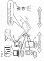
- the present invention is implemented by a configuration that includes user terminals 10a-10d and a router 20.
- the user terminals 10a-10d support a first wireless communication method.
- the router 20 is connected to a base station 30 via a second wireless communication method, different from the first wireless communication method described above, and functions as the wireless access point of the user terminals 10a-10d.
- the user terminals 10a-10d measure the wireless quality (first wireless quality) of the first wireless section, where the first wireless communication method is used, at a predetermined time interval and transmits the result to the router 20.
- the router 20 measures the wireless quality (second wireless quality) of the second wireless section where the second wireless communication method is used.
- the router 20 determines the contents to be displayed on each of the user terminals 10a-10d to indicate the radio wave state representing a state of a section ranging from the user terminal to the base station and then transmits the contents to each of the user terminals 10a-10d.
- the first wireless quality is the wireless quality of the first wireless section, where the first communication method is used, and is received from the user terminals 10a-10d
- the second wireless quality is the wireless quality of the second wireless section where the second wireless communication method is use
- Each of the user terminals 10a-10d displays the radio wave state in a section ranging from the user terminal to the base station, received from the router 20, using an icon on the screen or the radio wave display lamp.
- each terminal can display one of the first wireless quality and the second wireless quality, corresponding to a worse radio wave state ((Min(first wireless quality, second wireless quality)), in an incremental manner in terms (logos) of the number of antennas.
- This display allows the user to determine whether the terminal the user is currently using is connectable to an external network via the router 20.
- the number of antennas (logos) is decreased to indicate that the radio wave state is bad (see a mobile game terminal 10b in FIG. 1 )
- the user can take an action to approach the router 20, to switch to a wired connection, or to change the location of the router 20.
- a personal computer 10a a mobile game terminal 10b, a mobile music player 10c, and a tablet terminal 10d are shown as the user terminals in the example in FIG. 1 , the user terminal is not limited to those devices.
- FIG. 2 is a block diagram showing the configuration of the first exemplary embodiment of the present invention.
- FIG. 2 shows a user terminal 10; a router 20, and a base station 30.
- the user terminal 10 comprises a first wireless communication unit 11, a first wireless quality measurement unit 12, and a radio wave state display unit 14.
- the first wireless communication unit 11 accesses the router 20 using the first wireless communication method.
- the first wireless quality measurement unit 12 measures the wireless quality of the first wireless section (first wireless quality), where the first wireless communication method is used, and transmits the measured wireless quality to the router 20.
- the radio wave state display unit 14 displays the state of a radio wave received from the router 20.
- the first wireless communication method is a wireless LAN. Therefore, the first wireless communication unit 11 and the first wireless quality measurement unit 12 of the user terminal 10 may be implemented based on the wireless LAN communication function, provided in a wireless LAN capable apparatus, and the radio wave state measurement function that measures the radio field intensity (dB) of the router 20 and notifies the user whether wireless LAN communication can be performed.
- the near field wireless communication method such as Bluetooth (registered trademark) may also be used.
- the radio wave state display unit 14 is implemented by a program that displays the radio wave state, which will be described later, at a predetermined position on the screen of the user terminal 10 using an icon.
- the radio wave state display unit 14 may be implemented by a utility program, supplied from the vendor of the user terminal 10 or the router 20, or as a function of the operating system.
- the router 20 comprises a first wireless communication unit 21, a second wireless communication unit 22, a second wireless quality measurement unit 23, and a display contents determination unit 24.
- the first wireless communication unit 21 accepts access from the user terminal 10.
- the second wireless communication unit 22 connects to the base station 30 using the second wireless communication method, different from the first wireless communication method described above, and performs the function of the wireless access point.
- the second wireless quality measurement unit 23 measures the wireless quality of the second wireless section (second wireless quality), where the second wireless communication method is used, at a predetermined time interval.
- the display contents determination unit 24 determines the contents to be displayed on the radio wave state display unit 14 of the user terminal 10, based on the wireless quality of the first wireless section (first wireless quality) received from the user terminal 10 and the wireless quality of the second wireless section (second wireless quality), and transmits the determined contents to the user terminal 10.
- the base station 30 comprises a higher-level device communication unit 31 and a second wireless communication unit 32.
- the higher-level device communication unit 31 communicates with a higher-level device.
- the second wireless communication unit 32 communicates with the second wireless communication unit 22 of the router 20.
- the second wireless communication method is mobile WiMAX defined by IEEE802.16e-2005 and that the base station 30 is a WiMAX base station that configures a WiMAX network. Therefore, the first wireless communication unit 21, second wireless communication unit 22, and the second wireless quality measurement unit 23 of the router 20 may be implemented by the mobile WiMAX communication function provided in a mobile WiMAX router and by the measurement function of the wireless quality values, such as the Carrier to Interference and Noise Ratio (CINR) and the Received Signal Strength Indication (RSSI), to be reported to the WiMAX base station side.
- CINR Carrier to Interference and Noise Ratio
- RSSI Received Signal Strength Indication
- the successor method of mobile WiMAX WiMAX2, etc.
- Long Term Evolution LTE
- High Speed Downlink Packet Access HSDPA
- the second wireless communication unit 22 and the second wireless quality measurement unit 23 may be implemented by the function of a mobile router corresponding to those methods.
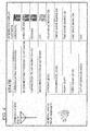
- FIG. 3 is a diagram showing an example of the table referenced by the display contents determination unit 24 to obtain the radio wave state to be displayed on the user terminal.
- the table indicates that the "out of service area" display is determined. This display allows the user to recognize that at least one of the wireless LAN and WiMAX is in the communication-disabled state.
- the table indicates the state as "out of service area (cannot receive display contents)" because the display contents cannot be received from the display contents determination unit 24.
- first wireless quality and second wireless quality exceed the lower limit threshold (THx1, THy1) but if one of them is equal to or lower than the next-higher threshold (THx2, THy2) of the lower-limit threshold (THx1, Thy1)
- the table indicates that the "very weak" display is determined. This display allows the user to recognize that at least one of the wireless LAN and WiMAX is in the bad communication state.
- both first wireless quality and second wireless quality are compared with four thresholds to determine the display contents as one of five levels, "out of service area” to "strong", the number of levels may be set arbitrarily. It is also possible to provide the "error" display to indicate an abnormal value of the first wireless quality and the second wireless quality.
- the Modulation and Coding Scheme (MCS) obtained by the router 20 side may also be used to determine the wireless quality level.
- FIG. 4 is a diagram showing an example of the contents integrally displayed on the radio wave state display unit 14 of the user terminal.
- the background color of the antenna indicates the communication state and, as the overall radio wave intensity, the number of wave marks represents the contents determined by the display contents determination unit 24 of the router 20.
- this exemplary embodiment allows the user, who accesses the Internet via the router 20, to monitor the radio wave state including the wireless state in a communication section extending beyond the router 20.
- the units (processing means) of the user terminal 10 and router 20 shown in FIG. 2 may also be implemented by a computer program that causes the computer, which configures the user terminal 10 and router 20, to execute the above-described processing on the hardware.
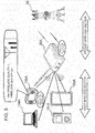
- FIG. 5 is a diagram showing the outline of the second exemplary embodiment of the present invention.
- the difference from the first exemplary embodiment is that a router 20A transmits the wireless quality of the second wireless section (second wireless quality to user terminals 10aA-10dA and that the user terminals 10aA - 10dA use the wireless quality of the first wireless section (first wireless quality), measured by each of the terminals, to determine and display the contents of the radio wave state from the user terminals to the base station.
- FIG. 6 is a block diagram showing a configuration of the second exemplary embodiment of the present invention.
- the difference from the configuration of the first exemplary embodiment shown in FIG. 2 is that a wireless quality reception unit 13 is added to the user terminal 10A and that a second wireless quality measurement unit 23A of the router 20A transmits the wireless quality of the second wireless section (second wireless quality) to the user terminal 10A.
- a radio wave state display unit 14A of the user terminal 10A receives the first and second wireless quality from a first wireless quality measurement unit 12A and the wireless quality reception unit 13 and performs the function corresponding to the display contents determination unit 24 of the router 20.
- the units (processing means) of the user terminal 10A and the router 20A shown in FIG. 6 may also be implemented by a computer program that causes the computer, which configures the user terminal 10A and the router 20A, to execute the above-described processing on the hardware.
- FIG. 7 is a diagram showing an example of the table referenced by the radio wave state display unit 14A of the user terminal 10A to obtain the contents to be displayed as the radio wave state in a section extending from the user terminal to the base station.
- This table is almost similar to that shown in FIG. 3 except that, if the first wireless quality is equal to or lower than the lower limit threshold, the table indicates the state as "out of service area (cannot receive second wireless quality)" because the second wireless quality cannot be received from the second wireless quality measurement unit 23A.
- the second wireless quality is transmitted via means other than a wireless LAN, there is no need for this distinction.
- the present invention may also be implemented by a configuration in which the user terminal 10A determines the display contents.
- the present invention is not limited to the exemplary embodiment described above and that any other modification, replacement, and adjustment may be added in the scope not departing from the basic technological concept of the present invention.
- the icons shown in Fig. 4 are used to notify the radio wave state to the user in the exemplary embodiment
- the user terminal or the router 20 may also display a change in the radio wave state (connection failure, recovery) and its failure location (first or second wireless section). Voice guidance may also be used as necessary.
- the radio wave state display system described in the first mode wherein if at least one of a value indicating the wireless quality of the first wireless section and a value indicating the wireless quality of the second wireless section is equal to or lower than a first threshold defined for each wireless quality, the radio wave state display means (or a radio wave state display unit) provides a display indicating that the user terminal is out of a service area.
- radio wave state display system described in the first or second mode wherein if both the value indicating the wireless quality of the first wireless section and the value indicating the wireless quality of the second wireless section exceed the first threshold but at least one of the values is equal to or lower than a second threshold that is higher than the first threshold, the radio wave state display means (or a radio wave state display unit) provides a display indicating that the radio wave state is worst.
- radio wave state display system described in one of the first to fifth modes wherein the radio wave display means (or a radio wave state display unit) displays a first icon that displays the radio wave state in an incremental manner and a second icon that displays the communication state of the user terminal in a color-coded image.
- the first wireless communication method is a wireless LAN or Bluetooth (registered trademark)
- the second wireless communication method is one of mobile WiMAX, WiMAX2, LTE, and HSDPA.
- the radio wave state display means (or the radio wave state display unit) provides a display indicating that the user terminal is out of a service area.
- the radio wave state display means (or the radio wave state display unit) provides a display indicating that the radio wave state is worst.
- the user terminal described in one of the eighth to tenth modes wherein the user terminal transmits the wireless quality information on the first wireless section to the router and displays the contents, received from the router, on the radio wave state display means (or the radio wave state display unit).
- the user terminal described in one of the eighth to tenth modes wherein the user terminal receives the wireless quality in on the second wireless section from the router and determines the display contents.
- the user terminal described in one of the eighth to twelfth modes wherein the radio wave display means (or the radio wave state display unit) displays a first icon that displays the radio wave state in an incremental manner and a second icon that displays the communication state of the user terminal in a color-coded image.
- the first wireless communication method is a wireless LAN or Bluetooth (registered trademark)
- the second wireless communication method is one of mobile WiMAX, WiMAX2, LTE, and HSDPA.
- a router that functions as a wireless access point of the user terminal described in one of the eighth to fourteenth modes and transmits wireless quality information on the second wireless section to the user terminal, wherein the wireless quality information is calculated based on a signal received from the base station connected via the second wireless communication method.
- a router that connects to a base station via a second wireless communication method and functions as a wireless access point of a user terminal working according to a first wireless communication method and that, based on both a wireless quality of a first wireless section where the first wireless communication method is used and a wireless quality of a second wireless section where the second wireless communication method is used, transmits contents to be displayed on the user terminal as a radio wave state, wherein the second wireless communication method is different from the first wireless communication method, the wireless quality of the first wireless section is received from the user terminal and measured by the user terminal, and the wireless quality of the second wireless section is measured by the router.
- a program causing a computer, installed in a user terminal working according to a first wireless communication method, to perform the processing of:
Landscapes
- Physics & Mathematics (AREA)
- Electromagnetism (AREA)
- Engineering & Computer Science (AREA)
- Computer Networks & Wireless Communication (AREA)
- Signal Processing (AREA)
- Mobile Radio Communication Systems (AREA)
- Telephone Function (AREA)
- Telephonic Communication Services (AREA)
Applications Claiming Priority (1)
| Application Number | Priority Date | Filing Date | Title |
|---|---|---|---|
| JP2011012671A JP5664276B2 (ja) | 2011-01-25 | 2011-01-25 | 電波状態表示システム、ユーザ端末、ルーター、電波状態表示方法およびプログラム |
Publications (2)
| Publication Number | Publication Date |
|---|---|
| EP2479908A2 true EP2479908A2 (de) | 2012-07-25 |
| EP2479908A3 EP2479908A3 (de) | 2015-08-19 |
Family
ID=45560708
Family Applications (1)
| Application Number | Title | Priority Date | Filing Date |
|---|---|---|---|
| EP12152385.6A Withdrawn EP2479908A3 (de) | 2011-01-25 | 2012-01-25 | Funkwellenstatusanzeigesystem, Benutzerendgerät, Router, Funkwellenstatusanzeigeverfahren und Programm |
Country Status (4)
| Country | Link |
|---|---|
| US (1) | US8724549B2 (de) |
| EP (1) | EP2479908A3 (de) |
| JP (1) | JP5664276B2 (de) |
| CN (1) | CN102625487B (de) |
Cited By (4)
| Publication number | Priority date | Publication date | Assignee | Title |
|---|---|---|---|---|
| EP3010284A1 (de) * | 2014-10-13 | 2016-04-20 | Vodafone IP Licensing limited | Aktivierung von zellularem verstärker |
| WO2016058934A1 (en) * | 2014-10-13 | 2016-04-21 | Vodafone Ip Licensing Limited | Cellular repeater activation |
| US10244568B2 (en) | 2014-10-13 | 2019-03-26 | Vodafone Ip Licensing Limited | Telecommunication system for relaying cellular coverage |
| EP3905760A4 (de) * | 2019-02-13 | 2022-03-09 | Huawei Technologies Co., Ltd. | Drahtlossignalqualitätsbeurteilungsverfahren, elektronische vorrichtung und system |
Families Citing this family (12)
| Publication number | Priority date | Publication date | Assignee | Title |
|---|---|---|---|---|
| JP5484540B2 (ja) * | 2012-09-26 | 2014-05-07 | ソフトバンクBb株式会社 | 中継装置及びプログラム |
| JP5911410B2 (ja) * | 2012-09-27 | 2016-04-27 | 株式会社Pfu | 画像読取システム、情報処理装置、画像読取装置、画像読取方法及びコンピュータプログラム |
| JP5925709B2 (ja) * | 2013-02-13 | 2016-05-25 | レノボ・シンガポール・プライベート・リミテッド | 無線端末装置、その電波状況表示方法、電波状況表示システム、及びコンピュータが実行可能なプログラム |
| CN103686808A (zh) * | 2013-12-06 | 2014-03-26 | 上海寰创通信科技股份有限公司 | 一种基于lte设备的网络运行状态获取装置及方法 |
| JP5921583B2 (ja) | 2014-01-29 | 2016-05-24 | ソフトバンク株式会社 | 電波状況報知装置、通信装置及びプログラム |
| JP6441962B2 (ja) * | 2014-12-25 | 2018-12-19 | 京セラ株式会社 | 電力管理システム、中継装置及び電力管理方法 |
| WO2016114270A1 (ja) | 2015-01-15 | 2016-07-21 | 株式会社リコー | 制御システム、通信端末、通信システム、制御方法、及びプログラム |
| JP6536068B2 (ja) * | 2015-02-19 | 2019-07-03 | 株式会社リコー | 制御システム、通信システム、制御方法、及びプログラム |
| JP2016178512A (ja) * | 2015-03-20 | 2016-10-06 | Kddi株式会社 | 無線通信装置 |
| CN106210930A (zh) * | 2016-06-30 | 2016-12-07 | 上海诺行信息技术有限公司 | 一种无线路由器的备用供电装置 |
| JP6534710B2 (ja) * | 2017-08-31 | 2019-06-26 | 本田技研工業株式会社 | 通信状態解析方法および通信状態解析システム |
| KR102588441B1 (ko) * | 2019-01-11 | 2023-10-12 | 삼성전자주식회사 | 무선 통신 시스템에서 백홀 링크를 구성하기 위한 장치 및 방법 |
Citations (1)
| Publication number | Priority date | Publication date | Assignee | Title |
|---|---|---|---|---|
| JP2002044729A (ja) | 2000-07-27 | 2002-02-08 | Sony Corp | 携帯無線端末 |
Family Cites Families (14)
| Publication number | Priority date | Publication date | Assignee | Title |
|---|---|---|---|---|
| JP3842500B2 (ja) * | 1999-11-10 | 2006-11-08 | 株式会社東芝 | 無線携帯端末装置 |
| JP4372300B2 (ja) * | 2000-02-25 | 2009-11-25 | 三菱電機株式会社 | 通信システム及び情報端末 |
| JP4090388B2 (ja) * | 2003-05-27 | 2008-05-28 | 三洋電機株式会社 | 電波受信装置 |
| JP4566524B2 (ja) * | 2003-05-29 | 2010-10-20 | 京セラ株式会社 | 無線通信システム、無線通信装置、無線通信端末 |
| JP2005204123A (ja) * | 2004-01-16 | 2005-07-28 | Matsushita Electric Ind Co Ltd | 移動体電子装置 |
| JP4487184B2 (ja) * | 2004-09-28 | 2010-06-23 | サクサ株式会社 | ベストポジション検索機能付中継機 |
| JP4652127B2 (ja) * | 2005-05-25 | 2011-03-16 | Necカシオモバイルコミュニケーションズ株式会社 | 移動通信端末 |
| JP2007150797A (ja) * | 2005-11-29 | 2007-06-14 | Matsushita Electric Ind Co Ltd | 無線通信装置および情報通知方法 |
| JP4999867B2 (ja) * | 2006-03-03 | 2012-08-15 | ケイティーフリーテル カンパニー リミテッド | 無線網品質測定方法及びシステム |
| JP5213353B2 (ja) * | 2007-05-17 | 2013-06-19 | キヤノン株式会社 | 通信端末、通信端末の制御方法、通信装置、通信装置の制御方法 |
| JP4564040B2 (ja) * | 2007-11-12 | 2010-10-20 | 京セラ株式会社 | 無線通信システム、無線通信装置、無線通信端末 |
| KR20090061434A (ko) * | 2007-12-11 | 2009-06-16 | 주식회사 케이티 | 네트워크 관리 시스템 및 그 방법 |
| JP5581597B2 (ja) * | 2009-02-05 | 2014-09-03 | 独立行政法人情報通信研究機構 | 携帯式通信中継装置 |
| JP5447158B2 (ja) * | 2010-04-30 | 2014-03-19 | 富士通株式会社 | 基地局装置、移動局装置、ハンドオーバ方法及びダウンロード方法 |
-
2011
- 2011-01-25 JP JP2011012671A patent/JP5664276B2/ja not_active Expired - Fee Related
-
2012
- 2012-01-18 CN CN201210020836.9A patent/CN102625487B/zh not_active Expired - Fee Related
- 2012-01-23 US US13/356,097 patent/US8724549B2/en not_active Expired - Fee Related
- 2012-01-25 EP EP12152385.6A patent/EP2479908A3/de not_active Withdrawn
Patent Citations (1)
| Publication number | Priority date | Publication date | Assignee | Title |
|---|---|---|---|---|
| JP2002044729A (ja) | 2000-07-27 | 2002-02-08 | Sony Corp | 携帯無線端末 |
Cited By (8)
| Publication number | Priority date | Publication date | Assignee | Title |
|---|---|---|---|---|
| EP3010284A1 (de) * | 2014-10-13 | 2016-04-20 | Vodafone IP Licensing limited | Aktivierung von zellularem verstärker |
| WO2016058934A1 (en) * | 2014-10-13 | 2016-04-21 | Vodafone Ip Licensing Limited | Cellular repeater activation |
| US10159111B2 (en) | 2014-10-13 | 2018-12-18 | Vodafone Ip Licensing Limited | Radio resource management in a telecommunication system |
| US10231284B2 (en) | 2014-10-13 | 2019-03-12 | Vodafone Ip Licensing Limited | Telecommunication system |
| US10244568B2 (en) | 2014-10-13 | 2019-03-26 | Vodafone Ip Licensing Limited | Telecommunication system for relaying cellular coverage |
| US10681752B2 (en) | 2014-10-13 | 2020-06-09 | Vodafone Ip Licensing Limited | Telecommunication system for relaying cellular coverage |
| EP3905760A4 (de) * | 2019-02-13 | 2022-03-09 | Huawei Technologies Co., Ltd. | Drahtlossignalqualitätsbeurteilungsverfahren, elektronische vorrichtung und system |
| US12156056B2 (en) | 2019-02-13 | 2024-11-26 | Huawei Technologies Co., Ltd. | Electronic device, apparatus, and method for quality evaluation and accuracy improvement of a wireless signal |
Also Published As
| Publication number | Publication date |
|---|---|
| EP2479908A3 (de) | 2015-08-19 |
| JP5664276B2 (ja) | 2015-02-04 |
| US20120188890A1 (en) | 2012-07-26 |
| CN102625487A (zh) | 2012-08-01 |
| CN102625487B (zh) | 2016-01-20 |
| US8724549B2 (en) | 2014-05-13 |
| JP2012156671A (ja) | 2012-08-16 |
Similar Documents
| Publication | Publication Date | Title |
|---|---|---|
| US8724549B2 (en) | Radio wave state display system, user terminal, router, radio wave state display method, and program | |
| US11115140B2 (en) | Signal strength measurement method, and related apparatus and system | |
| CN103581984A (zh) | Wlan空口质量监测方法与装置 | |
| GB2487120A (en) | Adaptive roaming for WLAN access points in a medical monitoring system | |
| US9491658B2 (en) | Systems and methods for determining congestion in wireless networks | |
| CN106535155A (zh) | 一种无线终端进行无线漫游的方法、装置和系统 | |
| US11190295B2 (en) | Remedial action based on inter-packet receive power | |
| US20150118969A1 (en) | Method and apparatus for measuring antenna space correlation, and terminal device | |
| WO2014070375A1 (en) | Dynamically adapting wireless communication | |
| US10432375B1 (en) | Wireless communication system and method having automatic self-configuration mechanism | |
| EP2464174A1 (de) | Verfahren, vorrichtung und system zur messung des grundrauschens eines basisstationsantennenanschlusses | |
| US8488478B1 (en) | Method and device for estimating RF interference in Wi-Fi communication by measuring time delays in RF transmission | |
| JP6484270B2 (ja) | 測定装置及び測定方法 | |
| CN105873118A (zh) | 室内Wi-Fi质量评估设备及方法 | |
| EP2755369A1 (de) | Anzeigedarstellung von zwei unterschiedlichen Signalqualitätswerten innerhalb eines einzigen Signalqualitätsanzeigers | |
| EP3361824A1 (de) | Verfahren zur steuerung einer funkzugangsausrüstung und vorrichtung damit | |
| US7127214B2 (en) | User perception of wireless improvement technology | |
| US20160212716A1 (en) | Method for detecting a terminal by a base station, base station, and network entity | |
| JP6383653B2 (ja) | 通信装置、通信品質推定方法及び通信品質推定用プログラム | |
| KR102103457B1 (ko) | 무선랜 시스템의 액세스 포인트 검색 방법 및 접속 관리 방법 | |
| JP5385879B2 (ja) | 無線通信速度検出装置およびその動作方法 | |
| JP4179958B2 (ja) | 携帯無線装置 | |
| US11824596B2 (en) | Base station operation test method, wireless communication system, and base station | |
| US20050070303A1 (en) | Level of service in a wireless telecommunications network | |
| KR102105685B1 (ko) | 무선랜 기반 데이터 트래픽 전송을 위한 최적 dfs 채널 선택 방법, 장치 및 컴퓨터 프로그램 |
Legal Events
| Date | Code | Title | Description |
|---|---|---|---|
| PUAI | Public reference made under article 153(3) epc to a published international application that has entered the european phase |
Free format text: ORIGINAL CODE: 0009012 |
|
| AK | Designated contracting states |
Kind code of ref document: A2 Designated state(s): AL AT BE BG CH CY CZ DE DK EE ES FI FR GB GR HR HU IE IS IT LI LT LU LV MC MK MT NL NO PL PT RO RS SE SI SK SM TR |
|
| AX | Request for extension of the european patent |
Extension state: BA ME |
|
| PUAL | Search report despatched |
Free format text: ORIGINAL CODE: 0009013 |
|
| AK | Designated contracting states |
Kind code of ref document: A3 Designated state(s): AL AT BE BG CH CY CZ DE DK EE ES FI FR GB GR HR HU IE IS IT LI LT LU LV MC MK MT NL NO PL PT RO RS SE SI SK SM TR |
|
| AX | Request for extension of the european patent |
Extension state: BA ME |
|
| 17P | Request for examination filed |
Effective date: 20160219 |
|
| RBV | Designated contracting states (corrected) |
Designated state(s): AL AT BE BG CH CY CZ DE DK EE ES FI FR GB GR HR HU IE IS IT LI LT LU LV MC MK MT NL NO PL PT RO RS SE SI SK SM TR |
|
| GRAP | Despatch of communication of intention to grant a patent |
Free format text: ORIGINAL CODE: EPIDOSNIGR1 |
|
| INTG | Intention to grant announced |
Effective date: 20171018 |
|
| RIC1 | Information provided on ipc code assigned before grant |
Ipc: H04B 17/23 20150101AFI20171006BHEP |
|
| STAA | Information on the status of an ep patent application or granted ep patent |
Free format text: STATUS: THE APPLICATION IS DEEMED TO BE WITHDRAWN |
|
| 18D | Application deemed to be withdrawn |
Effective date: 20180301 |