EP2479940B1 - Pseudowire-herstellungsverfahren und knotenvorrichtung - Google Patents
Pseudowire-herstellungsverfahren und knotenvorrichtung Download PDFInfo
- Publication number
- EP2479940B1 EP2479940B1 EP10816634.9A EP10816634A EP2479940B1 EP 2479940 B1 EP2479940 B1 EP 2479940B1 EP 10816634 A EP10816634 A EP 10816634A EP 2479940 B1 EP2479940 B1 EP 2479940B1
- Authority
- EP
- European Patent Office
- Prior art keywords
- service
- lsp
- bandwidth
- node
- priority
- Prior art date
- Legal status (The legal status is an assumption and is not a legal conclusion. Google has not performed a legal analysis and makes no representation as to the accuracy of the status listed.)
- Active
Links
Images



Classifications
-
- H—ELECTRICITY
- H04—ELECTRIC COMMUNICATION TECHNIQUE
- H04L—TRANSMISSION OF DIGITAL INFORMATION, e.g. TELEGRAPHIC COMMUNICATION
- H04L45/00—Routing or path finding of packets in data switching networks
- H04L45/50—Routing or path finding of packets in data switching networks using label swapping, e.g. multi-protocol label switch [MPLS]
-
- H—ELECTRICITY
- H04—ELECTRIC COMMUNICATION TECHNIQUE
- H04L—TRANSMISSION OF DIGITAL INFORMATION, e.g. TELEGRAPHIC COMMUNICATION
- H04L45/00—Routing or path finding of packets in data switching networks
- H04L45/68—Pseudowire emulation, e.g. IETF WG PWE3
-
- H—ELECTRICITY
- H04—ELECTRIC COMMUNICATION TECHNIQUE
- H04L—TRANSMISSION OF DIGITAL INFORMATION, e.g. TELEGRAPHIC COMMUNICATION
- H04L47/00—Traffic control in data switching networks
- H04L47/70—Admission control; Resource allocation
- H04L47/72—Admission control; Resource allocation using reservation actions during connection setup
- H04L47/724—Admission control; Resource allocation using reservation actions during connection setup at intermediate nodes, e.g. resource reservation protocol [RSVP]
-
- H—ELECTRICITY
- H04—ELECTRIC COMMUNICATION TECHNIQUE
- H04L—TRANSMISSION OF DIGITAL INFORMATION, e.g. TELEGRAPHIC COMMUNICATION
- H04L47/00—Traffic control in data switching networks
- H04L47/70—Admission control; Resource allocation
- H04L47/80—Actions related to the user profile or the type of traffic
- H04L47/805—QOS or priority aware
-
- H—ELECTRICITY
- H04—ELECTRIC COMMUNICATION TECHNIQUE
- H04L—TRANSMISSION OF DIGITAL INFORMATION, e.g. TELEGRAPHIC COMMUNICATION
- H04L47/00—Traffic control in data switching networks
- H04L47/70—Admission control; Resource allocation
- H04L47/82—Miscellaneous aspects
- H04L47/825—Involving tunnels, e.g. MPLS
Definitions
- the present invention relates to the communication field, and in particular, to a pseudowire setup method and a node device.
- IP Internet Protocol
- MSTP Multi-Service Transport Platform
- Microwaves are widely applied in operator networks.
- SDH microwaves and Plesiochronous Digital Hierarchy (PDH) microwaves are prevalent.
- PTN device replacing the SDH device
- the packet microwave device begins to correspondingly replace the SDH/PDH microwave device accordingly, and has been applied massively in the market in recent years.
- PWE3 Pseudowire Edge to Edge Emulation
- PWE3 allows edge-to-edge emulation of different services in the network made up of data devices, such that the data network may support different service types.
- This is implemented by pseudowire in a manner that, by configuring a mapping relationship among a service, a pseudowire label and the packet switching path at two ends of the packet switching path, the pseudowires present on a mapping packet switching path become a layer between the service and the packet switching path, and separates the packet switching path from the service, allowing the packet switching to deal with various services in a nondiscriminatory way by imparting some features to the pseudowire.
- a packet switching path bears multiple pseudowires.
- multi-hop pseudowire means that a pseudowire traverses multiple packet switching paths, which usually occurs when the emulated service extends across different domains.
- Pseudowire setup is aiming at setting up the mapping relationship among the service, the pseudowire label, and the packet switching path automatically.
- Current multi-hop pseudowire setup method includes sending a label mapping message on the originating side according to a Label Distribution Protocol (LDP) signaling, in which the label mapping message carries a pseudowire label, an explicit route (IP address of each node), and bandwidth information; configuring the mapping relationship related to the pseudowire label on each hop; selecting the packet switching path to the next hop according to bandwidth information and next hop IP address; configuring correspondingly to generate the pseudowire label to the next hop and then forwarding the label mapping message to the next hop.
- LDP Label Distribution Protocol
- the prior art has at least the following disadvantages. Because the bandwidth allocated to services with different service levels is not bounded, when the pseudowire is applied to the packet microwave device, the following problem occurs.
- the bandwidth of the microwave link varies with weather conditions, but the bandwidth allocated to services with different service levels is not bounded, and therefore, services with low service level and services with high service level will share bandwidth; when the bandwidth decreases, if too many pseudowires are set up on the packet switching path to emulate the services with high service level, the service packets with high service level may be discarded or interrupted, and the services with low service level may occupy too much bandwidth.
- QoS Quality of Service
- US 2004/0156313 A1 discloses a method, apparatus and network for transporting layer-2 frames, such as Ethernet MAC, ATM AAL5, and Frame Relay, over MPLS, SONET/SDH, or OTN optical transport networks as well as electrical transport networks is disclosed.
- the method establishes "pseudo-wires" between, for example, routers, Layer-2 packet switches, or SONET/SDH switches.
- Inter-related ingress and egress resource tables may be used by provider edge nodes to negotiate consistently managed data tunnels across a provider network on behalf of data flowing from/to a diverse base of customer edge nodes.
- LDP Label Distribution Protocol
- rfc4447 discloses that Layer 2 services (such as Frame Relay, Asyncronus Transfer Mode, Ethernet) can be "emulated” over an MPLS backbone by encapsulating the layer 2 Packet Data Units (PDU) and then transmitting them over "pseudowires".
- PDU Packet Data Units
- pseudowires to provide low-rate Time Dividion Multiplexed and a Synchronous Optical NETworking circuit emulation over a MPLS enabled network.
- This document specifies a protocol for establishing and maintaining the pseudowires, using extensions to Label Distribution Protocol (LDP). Procedures for encapsulating layer 2 PDUs are specified in a set of companion documents.
- a Multi-Segment PW is defined as a set of two or more contiguous PW segments that behave and function as a single point-to-point PW. This document describes extensions to the PW control protocol to dynamically place the segments of the multi segment pseudowire among a set of Provider Edge (PE) routers.
- PE Provider Edge
- These domains can be autonomous systems under one provider administrative control, IGP areas in one autonomous system, different autonomous systems under the administrative control of two or more service providers, or administratively established pseudo-wire domains.
- RSVP-TE Resource Reservation Protocol-Traffic Engineering
- PW QoS the setup of a multi-hop PW, for example, to span multiple domains.
- RSVP-TE provides mechanisms for QoS signaling and these can be leveraged for signaling PW QoS. It also provides the ability to signal bi-directional MPLS Label Switched Paths (LSP) with explicit routes. This can be used for signaling multi-hop PWs that require explicit routing. RSVP-TE also provides the ability to establish non- adjacent or targeted signaling sessions.
- RSVP-TE Extensions to RSVP far LSP Tunnels; rfc3249 clarifies published RFCs which standardize facsimile communications using Internet Email. The intent is to prevent implementations that deviate in such a way as to cause interoperability problems.
- Embodiments of the present invention provide a pseudowire setup method and a node device to ensure QoS of an established pseudowire.
- an embodiment of the present invention provides a pseudowire setup method, including: receiving, by a node, a label mapping message which carries a bandwidth required by a service and a priority of the service, wherein a Label Switching Path, LSP, in which the node is located comprise a microwave link, and wherein information about multiple priorities supported by the LSP and the remaining bandwidth quota corresponding to the multiple priorities is stored in the node according to the bandwidth of the microwave link in different environments; judging, by the node, whether the LSP supports the priority of the service and the bandwidth of the service, according to bandwidth supporting information of the LSP, and the bandwidth required by the service and the priority of the service which are carried in the label mapping message, wherein the bandwidth supporting informations of the LSP is the information about multiple priorities supported by the LSP and the remaining bandwidth quota corresponding to the multiple priorities, wherein the bandwidth required by the service and the priority of the service are supported by the LSP when the priority of the service is supported by the LSP and the remaining bandwidth quota corresponding to
- an embodiment of the present invention provides a node device, including: a storage unit, configured to store bandwidth supporting information of a Label Switching Path, LSP, in which the node device is located, wherein the LSP comprise a microwave link, wherein information about multiple priorities supported by the LSP and the remaining bandwidth quota corresponding to the multiple priorities is stored in the node according to the bandwidth of the microwave link in different environments, wherein the bandwidth supporting information of the LSP is the information about multiple priorities supported by the LSP and the remaining bandwidth quota corresponding to the multiple priorities; a receiving unit (601a, 601), configured to receive a label mapping message that carries a bandwidth required by a service and a priority of the service; and a processing unit, configured to judge whether the LSP supports the priority of the service and the bandwidth of the service, according to the bandwidth supporting information of the LSP, and the bandwidth required by the service and the priority of the service which are carried in the label mapping message, wherein the bandwidth required by the service and the priority of the service are supported by the L
- the foregoing technical solutions have the following benefits: judging whether the LSP in which the node is located supports the service level of the service and the bandwidth of the service according to the bandwidth supporting information, which is stored in the node, of the LSP in which the node is located and the bandwidth required by the service and the service level of the service that are carried in the label mapping message; and using the LSP as an LSP which bears a pseudowire when it is judged that the LSP supports the service level of the service and the bandwidth of the service, thus determining the service level of the service allowed to pass through the LSP and the bandwidth corresponding to the service level by configuring the bandwidth supporting information, which is stored in the node, of the LSP in which the node is located. Therefore, services in different service levels may be treated discriminatorily according to requirements, and the QoS of the pseudowire may be ensured when the bandwidth decreases.
- FIG. 1 is a flowchart of a pseudowire setup method according to an embodiment of the present invention. The method includes the following steps.
- the label mapping message may further include a pseudowire label; and the pseudowire label may be also obtained from the label mapping message; and a mapping relationship between the pseudowire label and the LSP may be configured.
- the label mapping message may further include a source node identifier; and error information is returned to the source node according to the source node identifier when it is judged that the LSP in which the node is located fails to support the service level of the service and/or the bandwidth of the service (namely, the LSP may not support the service level; or the LSP may support the service level but the remaining bandwidth quota corresponding to the service level is not enough).
- whether the LSP in which the node is located supports the service level of the service and the bandwidth of the service is judged according to the bandwidth supporting information, which is stored in the node, of the LSP in which the node is located and the bandwidth required by the service and service level of the service that are carried in the label mapping message; and the LSP is used as an LSP which bears the pseudowire when it is judged that the LSP supports the service level of the service and the bandwidth of the service.
- the bandwidth supporting information, which is stored in the node, of the LSP in which the node is located may be configured, the service level of the service allowed to pass through the LSP and the bandwidth corresponding to the service level may be decided. Therefore, services with different service levels may be treated discriminatorily according to requirements, and the QoS of the established pseudowire may be ensured when the bandwidth decreases.
- FIG. 1 is a flowchart of a pseudowire setup method according to the embodiment of the present invention. The method includes the following steps.
- the label mapping message may further include a pseudowire label; and the pseudowire label may be obtained from the label mapping message; and a mapping relationship between the pseudowire label and the LSP may be configured.
- the label mapping message may further include a source node identifier; and error information is returned to the source node according to the source node identifier when it is judged that the LSP in which the node is located does not support the priority of the service and/or the bandwidth of the service (namely, the LSP may not support the priority; or the LSP may support the priority but the remaining bandwidth quota corresponding to the priority is not enough).
- whether the LSP in which the node is located supports the priority of the service and the bandwidth of the service is judged according to the bandwidth supporting information, which is stored in the node, of the LSP in which the node is located and the bandwidth required by the service and priority of the service that are carried in the label mapping message; and the LSP is used as an LSP which bears the pseudowire when it is judged that the LSP supports the priority of the service and the bandwidth of the service.
- the bandwidth supporting information, which is stored in the node, of the LSP in which the node is located may be configured, the priority of the service allowed to pass through the LSP and the bandwidth corresponding to the priority may be decided. Therefore, services of different priorities may be treated discriminatorily according to requirements, and the QoS of the established pseudowire may be ensured when the bandwidth decreases.
- FIG. 3 is an abstract diagram of FIG. 2 .
- This is a Multi-Protocol Label Switching (MPLS) network which is divided into two segments: a network segment 105 and a network segment 106.
- the two network segments may be connected through a node 103, a service is added and dropped on node 101 and node 102, an LSP-201 is set up between the node 101 and the node 103, and an LSP-202 is set up between the node 102 and the node 103.
- a link 104 is a microwave link. Due to adaptive modulation, the link bandwidth changes with the environment (the current devices may support bandwidth adjustment of up to 16 levels), which leads to corresponding change of the bandwidth of the LSP-202.
- a pseudowire is set up as follows: Assume that a pseudowire needs to be set up for a service 203 (bandwidth 20Mbps), and the node 101 initiates a setup signaling.
- Step 0a Configure bandwidth quota for each service priority on a endpoint 102 and endpoint 103 of the LSP-202 according to the bandwidth of the microwave link in different environments, and maintain the current forward (in the direction from 101 to 102) and reverse (in the direction from 102 to 101) remaining bandwidth quota.
- FIG. 4 is a schematic diagram of a bandwidth quota table of an LSP-202 according to an embodiment of the present invention.
- Step 0b Determine the priority of the service 203 according to configuration. Assume that the priority of the service 203 is configured as 6.
- Step 1 The node 101 selects, according to information such as the Target Attachment Individual Identifier (TAII) and the bandwidth requirement (namely, requested bandwidth), the LSP-201 to bear a first hop of pseudowire, and initiates a label mapping signaling directly.
- TAII Target Attachment Individual Identifier
- PW Pseudowire
- TLV Priority Type Length Value
- the label mapping message needs to carry the previously defined PW Bandwidth TLV to indicate information such as the bandwidth requirement and the TAII.
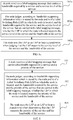
- FIG. 5 shows information about each TLV carried in a label mapping message, as described below:
- Step 2 After receiving the label mapping signaling initiated by the node 101, the node 103 selects an LSP that bears this hop of pseudowire according to information indicating that a destination Provider Edge (PE) node is the node 103, the requested bandwidth and the priority that are carried in the label mapping signaling.
- PE Provider Edge
- the node 103 selects the LSP-202 as an LSP which bears the pseudowire, configures a mapping relationship between the corresponding pseudowire label and the LSP, and subtracts 30 Mbps from the reverse remaining bandwidth, and then the process proceeds to step 3.
- the node 103 If the requested bandwidth is 50 Mbps and the LSP between the node 102 and the node 103 does not support the priority, or, if the LSP supports the priority but the remaining bandwidth quota corresponding to the priority is not enough, the node 103 returns error information "the bandwidth of this priority cannot be satisfied" to the previous hop 101.
- Step 3 The node 103 sends a label mapping message to the node 102 to set up a second hop of the pseudowire.
- the information carried in the label mapping message is similar to that carried in the message sent in step 1 except for changes of the PW label. Additionally, a PW exchange relationship needs to be set up on the node 103 according to the PW label of the previous hop and the PW label of this hop.
- Step 4 The node 102 receives the label mapping message sent by the node 103, and judges, according to the TAII information carried in the message, that the current node is the last-hop node. Therefore, the node 102 configures a mapping relationship among the corresponding service, the pseudowire label, and the LSP, and initiates a reverse label mapping signaling to complete setting up the bidirectional mapping of the pseudowire.
- the reverse signaling process is similar to the signaling process described above except for the need of checking whether the forward bandwidth quota meets the bandwidth requirement.
- the reverse remaining bandwidth is maintained through the forward signaling, and the forward remaining bandwidth is maintained through the reverse signaling. Both forward remaining bandwidth and the reverse remaining bandwidth may be maintained through the forward signaling or the reverse signaling uniformly.
- the label mapping signaling carries priority information and bandwidth requirement information; each hop of node on the pseudowire selects the tunnel according to the foregoing information, and therefore, the pseudowire setup can be controlled based on the priority of the service, and the QoS of the established pseudowire is ensured to the greatest extent.
- FIG. 3 is an abstract diagram of FIG. 2 .
- a MPLS network is divided into two segments: a network segment 105 and a network segment 106.
- the two network segments may be connected through a node 103, a service is added and dropped on node 101 and a node 102, an LSP-201 is set up between the node 101 and the node 103, and an LSP-202 is set up between the node 102 and the node 103.
- a link 104 is a microwave link. Due to adaptive modulation, the link bandwidth changes with the environment (currently, the device may support bandwidth adjustment of up to 16 levels), which leads to corresponding change of the bandwidth of the LSP-202.
- a process of setting up a pseudowire is as follows: Assume that a pseudowire needs to be set up for a service 203 (bandwidth 20Mbps), and the node 101 initiates a setup signaling.
- Step 0a Configure bandwidth quota for each service availability level on an endpoint 102 and endpoint 103 of the LSP-202 according to the bandwidth of the microwave link in different environments, and maintain the current forward remaining bandwidth quota (in the direction from the node 101 to the node 102) and the reverse remaining bandwidth quota (in the direction from the node 102 to the node 101).
- FIG. 4a is a schematic diagram of a bandwidth quota table of an LSP-202 in the case of different availabilities according to an embodiment of the present invention.
- Step 0b Determine the service availability of the service 203 according to configuration. Assume that the service availability of the service 203 is configured as 99.995%.
- Step 1 The node 101 selects, according to information such as the TAII and the bandwidth requirement (namely, requested bandwidth), the LSP-201 to bear a first hop of pseudowire, and initiates a label mapping signaling directly.
- a new PW Availability TLV is defined in the label mapping message to carry availability information. Additionally, the label mapping message needs to include the previously defined PW Bandwidth TLV to indicate information such as the bandwidth requirement and the TAII.
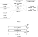
- FIG. 5a shows information about each TLV carried in a label mapping message, as described below:
- Step 2 After receiving the label mapping signaling initiated by the node 101, the node 103 selects, according to the information indicating that a destination PE node is the node 103, the requested bandwidth and the priority that are carried in the label mapping signaling, an LSP that bears this hop of pseudowire.
- the node 103 selects the LSP-202 as an LSP which bears the pseudowire, configures a mapping relationship between the corresponding pseudowire label and the LSP, and subtracts 30 Mbps from the reverse remaining bandwidth, and then the procedure proceeds to step 3.
- the node 103 If the requested bandwidth is 50 Mbps and the availability supported by the LSP between the node 102 and the node 103 is lower than the requested availability, or, if the LSP supports the corresponding availability but the remaining bandwidth quota corresponding to the availability is not enough, the node 103 returns error information "the requested bandwidth cannot be satisfied" to the previous hop 101.
- Step 3 The node 103 sends a label mapping message to the node 102 to set up a second hop of the pseudowire.
- the information carried in the label mapping message is similar to that carried in the message sent in step 1 except for changes of the PW label. Additionally, a PW exchange relationship needs to be set up on the node 103 according to the PW label of the previous hop and the PW label of this hop.
- Step 4 The node 102 receives the label mapping message sent by the node 103, and judges, according to the TAII information carried in the message, that the current node is the last-hop node. Therefore, the node 102 configures the mapping relationship among the corresponding service, the pseudowire label, and the LSP, and initiates a reverse label mapping signaling to complete setting up the bidirectional mapping of the pseudowire.
- the reverse signaling process is similar to the signaling process described above except for the need of checking whether the forward bandwidth quota meets the bandwidth requirement.
- the reverse remaining bandwidth is maintained through the forward signaling, and the forward remaining bandwidth is maintained through the reverse signaling. Both forward remaining bandwidth and the reverse remaining bandwidth may be maintained through the forward signaling or the reverse signaling uniformly.
- the label mapping signaling carries availability information and bandwidth requirement information; each hop of node on the pseudowire selects a tunnel according to the foregoing information, and therefore, the pseudowire setup may be controlled based on the availability of the service, and the QoS of the established pseudowire is ensured to the greatest extent.
- FIG. 6a is a schematic structural diagram of a node device according to an embodiment of the present invention.
- the node device includes:
- the service level includes any one or combination of a service priority, service availability level, and service type.
- the storage unit 603a is specifically configured to store multiple service levels of multiple services supported by the LSP in which the node device is located and the remaining bandwidth quota corresponding to the multiple service levels.
- FIG. 7a is a schematic structural diagram of a processing unit according to an embodiment of the present invention.
- the processing unit 602a may include: a judging subunit 6021a, configured to: compare the obtained service level of the service and bandwidth required by the service with the stored service level and remaining bandwidth quota; and judge that the LSP in which the node device is located supports the bandwidth required by the service of the service level when determining that the LSP supports the service level of the service, and the remaining bandwidth quota corresponding to the service level of the service is greater than the bandwidth required by the service; and a confirming subunit 6022a, configured to use the LSP as an LSP which bears a pseudowire when judging that the LSP in which the node device is located supports the service level of the service and the bandwidth of the service.
- FIG. 8a is another schematic structural diagram of a node device according to an embodiment of the present invention.
- the device includes the foregoing storage unit 603a, receiving unit 601a, and processing unit 602a.
- the label mapping message may further include a pseudowire label, and the device may further include: a first obtaining unit 604a, configured to obtain the pseudowire label from the label mapping message; and a first configuring unit 605a, configured to configure a mapping relationship between the pseudowire label and the LSP.
- the label mapping message may further include a source node identifier, and the device may further include: a second obtaining unit 606a, configured to obtain a source node identifier from the label mapping message.
- the processing unit 602a is further configured to return error information to the source node according to the source node identifier when it is judged that the LSP in which the node device is located does not support the service level of the service and/or the bandwidth requirement of the service (namely, the LSP may not support the service level; or the LSP may support the service level but the remaining bandwidth quota corresponding to the service level is not enough).
- whether the LSP in which the node is located supports the service level of the service and the bandwidth of the service is judged according to the bandwidth supporting information which is stored by the node and is of the LSP in which the node is located and the bandwidth required by the service and service level of the service that are carried in the label mapping message; and the LSP is used as an LSP which bears the pseudowire when it is judged that the LSP supports the service level of the service and the bandwidth of the service.
- the bandwidth supporting information which is stored by the node and is of the LSP in which the node is located may be configured, the service level of the service allowed for passing through the LSP and the bandwidth corresponding to the service level may be decided. Therefore, services with different service levels may be treated discriminatorily according to requirements, and the QoS of the established pseudowire may be ensured when the bandwidth decreases.
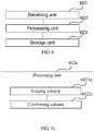
- FIG. 6 is a schematic structural diagram of a node device according to an embodiment of the present invention.
- the device includes:
- the storage unit 603 is specifically configured to store multiple service priorities of multiple services supported by the LSP in which the node device is located and the remaining bandwidth quota corresponding to the multiple priorities.
- FIG. 7 is a schematic structural diagram of a processing unit according to an embodiment of the present invention.
- the processing unit 602 may include: a judging subunit 6021, configured to: compare the obtained priority of the service and bandwidth required by the service with the stored priority and remaining bandwidth quota; and judge that the LSP in which the node device is located supports the bandwidth required by the service of the priority when determining that the LSP supports the priority of the service, and the remaining bandwidth quota corresponding to the priority of the service is greater than the bandwidth required by the service; and a confirming subunit 6022, configured to use the LSP as an LSP which bears the pseudowire when it is judged that the LSP in which the node device is located supports the priority of the service and the bandwidth of the service.
- FIG. 8 is another schematic structural diagram of a node device according to an embodiment of the present invention.
- the device includes the foregoing storage unit 603, receiving unit 601, and processing unit 602.
- the label mapping message may further carry a pseudowire label, and the device may further include: a first obtaining unit 604, configured to obtain the pseudowire label from the label mapping message; and a first configuring unit 605, configured to configure a mapping relationship between the pseudowire label and the LSP.
- the label mapping message may further carry a source node identifier, and the device may further include: a second obtaining unit 606, configured to obtain a source node identifier from the label mapping message.
- the processing unit 602 is further configured to return error information to the source node according to the source node identifier when it is judged that the LSP in which the node device is located does not support the priority of the service and/or the bandwidth requirement of the service (namely, the LSP may not support the priority; or the LSP may support the priority but the remaining bandwidth quota corresponding to the priority is not enough).
- whether the LSP in which the node is located supports the priority of the service and the bandwidth of the service is judged according to the bandwidth supporting information which is stored by the node and is of the LSP in which the node is located and the bandwidth required by the service and priority of the service that are carried in the label mapping message; and the LSP is used as an LSP which bears the pseudowire when it is judged that the LSP supports the priority of the service and the bandwidth of the service.
- the bandwidth supporting information which is stored by the node and is of the LSP in which the node is located may be configured, the priority of the service allowed for passing through the LSP and the bandwidth corresponding to the priority may be decided. Therefore, services of different priorities may be treated discriminatorily according to requirements, and the QoS of the established pseudowire may be ensured when the bandwidth decreases.
Landscapes
- Engineering & Computer Science (AREA)
- Computer Networks & Wireless Communication (AREA)
- Signal Processing (AREA)
- Data Exchanges In Wide-Area Networks (AREA)
Claims (6)
- Pseudodrahteinrichtungsverfahren, das Folgendes umfasst:Empfangen (101) durch einen Knoten einer "Label Mapping Message", die eine von einem Dienst benötigte Bandbreite und eine Priorität des Dienstes enthält, wobei ein "Label Switching Path", LSP, in dem sich der Knoten befindet, eine Mikrowellenverbindung umfasst und wobei Informationen über mehrere vom LSP unterstützte Prioritäten und die den mehreren Prioritäten entsprechende verbleibende Bandbreitenquote gemäß der Bandbreite der Mikrowellenverbindung in verschiedenen Umgebungen im Knoten gespeichert sind;Beurteilen (102) durch den Knoten, ob der LSP die Priorität des Dienstes und die Bandbreite des Dienstes gemäß den Bandbreitenunterstützungsinformationen des LSP sowie der vom Dienst benötigten Bandbreite und der Priorität des Dienstes, die in der "Label Mapping Message" enthalten sind, unterstützt, wobei die Bandbreitenunterstützungsinformationen des LSP die Informationen über mehrere vom LSP unterstützte Prioritäten und die den mehreren Prioritäten entsprechende im Knoten gespeicherte verbleibende Bandbreitenquote sind, wobei die vom Dienst benötigte Bandbreite und die Priorität des Dienstes vom LSP unterstützt werden, wenn die Priorität des Dienstes vom LSP unterstützt wird und die der Priorität des Dienstes entsprechende verbleibende Bandbreitenquote größer ist als die vom Dienst benötigte Bandbreite; undVerwenden des LSP als einen LSP, der einen Pseudodraht trägt, wenn beurteilt wird, dass der LSP die Priorität des Dienstes und die Bandbreite des Dienstes unterstützt (103).
- Verfahren nach Anspruch 1, wobei:die "Label Mapping Message" ferner ein Pseudodraht-Label umfasst und das Verfahren ferner umfasst:Erhalten des Pseudodraht-Labels von der "Label Mapping Message" und Auslegen einer Mapping-Beziehung zwischen dem Pseudodraht-Label und dem LSP.
- Verfahren nach Anspruch 1, wobei:die "Label Mapping Message" ferner eine Quellknotenkennung umfasst und das Verfahren ferner umfasst:Zurückgeben von Fehlerinformationen an einen Quellknoten gemäß der Quellknotenkennung, wenn beurteilt wird, dass der LSP, in dem der Knoten sich befindet, die Priorität des Dienstes und/oder die Bandbreite des Dienstes nicht unterstützt.
- Knotenvorrichtung, die Folgendes umfasst:eine Speichereinheit (603a, 603), die dazu ausgelegt ist, Bandbreitenunterstützungsinformationen eines "Label Switching Path", LSP, in dem die Knotenvorrichtung sich befindet, zu speichern, wobei der LSP eine Mikrowellenverbindung umfasst, wobei Informationen über mehrere vom LSP unterstützte Prioritäten und die den mehreren Prioritäten entsprechende verbleibende Bandbreitenquote gemäß der Bandbreite der Mikrowellenverbindung in verschiedenen Umgebungen im Knoten gespeichert sind, wobei die Bandbreitenunterstützungsinformationen des LSP die Informationen über mehrere vom LSP unterstützte Prioritäten und die den mehreren Prioritäten entsprechende im Knoten gespeicherte verbleibende Bandbreitenquote sind;eine Empfangseinheit (601a, 601), die dazu ausgelegt ist, eine "Label Mapping Message" zu empfangen, die eine von einem Dienst benötigte Bandbreite und eine Priorität des Dienstes enthält; undeine Verarbeitungseinheit (602a, 602) die dazu ausgelegt ist zu beurteilen, ob der LSP die Priorität des Dienstes und die Bandbreite des Dienstes gemäß den Bandbreitenunterstützungsinformationen des LSP sowie der vom Dienst benötigten Bandbreite und der Priorität des Dienstes, die in der "Label Mapping Message" enthalten sind, unterstützt, wobei die vom Dienst benötigte Bandbreite und die Priorität des Dienstes vom LSP unterstützt werden, wenn die Priorität des Dienstes vom LSP unterstützt wird und die der Priorität des Dienstes entsprechende verbleibende Bandbreitenquote größer ist als die vom Dienst benötigte Bandbreite; und den LSP als einen LSP, der einen Pseudodraht trägt, zu verwenden, wenn beurteilt wird, dass der LSP die Priorität des Dienstes und die Bandbreite des Dienstes unterstützt.
- Vorrichtung nach Anspruch 4, wobei:die "Label Mapping Message" ferner ein Pseudodraht-Label umfasst und die Vorrichtung ferner umfasst:eine erste erhaltende Einheit (604; 604a), die dazu ausgelegt ist, das Pseudodraht-Label von der "Label Mapping Message" zu erhalten; undeine erste Auslegungseinheit (605; 605a), die dazu ausgelegt ist, eine Mapping-Beziehung zwischen dem Pseudodraht-Label und dem LSP einzustellen.
- Vorrichtung nach Anspruch 4, wobei:die "Label Mapping Message" ferner eine Quellknotenkennung umfasst und die Vorrichtung ferner umfasst:eine zweite erhaltende Einheit (606; 606a), die dazu ausgelegt ist, die Quellknotenkennung von der "Label Mapping Message" zu erhalten, wobei die Verarbeitungseinheit (602; 602a) ferner dazu ausgelegt ist, gemäß der Quellknotenkennung Fehlerinformationen an einen Quellknoten zurückzugeben, wenn beurteilt wird, dass der LSP, in dem die Knotenvorrichtung sich befindet, die Priorität des Dienstes und/oder die Bandbreite des Dienstes nicht unterstützt.
Priority Applications (1)
| Application Number | Priority Date | Filing Date | Title |
|---|---|---|---|
| EP17186803.7A EP3313028B1 (de) | 2009-09-17 | 2010-07-26 | Pseudodrahteinrichtungsverfahren und knotenvorrichtung |
Applications Claiming Priority (2)
| Application Number | Priority Date | Filing Date | Title |
|---|---|---|---|
| CN200910173932A CN101656673A (zh) | 2009-09-17 | 2009-09-17 | 一种伪线建立方法和节点装置 |
| PCT/CN2010/075458 WO2011032430A1 (zh) | 2009-09-17 | 2010-07-26 | 一种伪线建立方法和节点装置 |
Related Child Applications (1)
| Application Number | Title | Priority Date | Filing Date |
|---|---|---|---|
| EP17186803.7A Division EP3313028B1 (de) | 2009-09-17 | 2010-07-26 | Pseudodrahteinrichtungsverfahren und knotenvorrichtung |
Publications (3)
| Publication Number | Publication Date |
|---|---|
| EP2479940A4 EP2479940A4 (de) | 2012-07-25 |
| EP2479940A1 EP2479940A1 (de) | 2012-07-25 |
| EP2479940B1 true EP2479940B1 (de) | 2017-09-06 |
Family
ID=41710770
Family Applications (2)
| Application Number | Title | Priority Date | Filing Date |
|---|---|---|---|
| EP17186803.7A Active EP3313028B1 (de) | 2009-09-17 | 2010-07-26 | Pseudodrahteinrichtungsverfahren und knotenvorrichtung |
| EP10816634.9A Active EP2479940B1 (de) | 2009-09-17 | 2010-07-26 | Pseudowire-herstellungsverfahren und knotenvorrichtung |
Family Applications Before (1)
| Application Number | Title | Priority Date | Filing Date |
|---|---|---|---|
| EP17186803.7A Active EP3313028B1 (de) | 2009-09-17 | 2010-07-26 | Pseudodrahteinrichtungsverfahren und knotenvorrichtung |
Country Status (5)
| Country | Link |
|---|---|
| US (1) | US8897136B2 (de) |
| EP (2) | EP3313028B1 (de) |
| CN (1) | CN101656673A (de) |
| ES (2) | ES2643466T3 (de) |
| WO (1) | WO2011032430A1 (de) |
Families Citing this family (31)
| Publication number | Priority date | Publication date | Assignee | Title |
|---|---|---|---|---|
| CN101656673A (zh) * | 2009-09-17 | 2010-02-24 | 华为技术有限公司 | 一种伪线建立方法和节点装置 |
| CN102195870A (zh) * | 2010-03-01 | 2011-09-21 | 中兴通讯股份有限公司 | 伪线迁移方法及装置 |
| CN102148748B (zh) * | 2010-10-26 | 2014-05-21 | 华为技术有限公司 | 伪线路由扩散方法、系统和汇聚节点设备 |
| CN102143066B (zh) * | 2011-02-17 | 2014-12-24 | 华为技术有限公司 | 建立标签交换路径的方法、节点设备和系统 |
| US8848716B2 (en) * | 2011-04-11 | 2014-09-30 | Cisco Technology, Inc. | Termination of a pseudowires on multiple line cards |
| CN102904809B (zh) * | 2011-07-26 | 2016-08-03 | 华为技术有限公司 | 标签转发路径的带宽资源管理方法、装置和系统 |
| US9049233B2 (en) | 2012-10-05 | 2015-06-02 | Cisco Technology, Inc. | MPLS segment-routing |
| CN102916842A (zh) * | 2012-11-06 | 2013-02-06 | 烽火通信科技股份有限公司 | 利用多种保护方式叠加实现ptn设备双归保护的方法 |
| US10587505B1 (en) | 2012-12-27 | 2020-03-10 | Sitting Man, Llc | Routing methods, systems, and computer program products |
| US10476787B1 (en) | 2012-12-27 | 2019-11-12 | Sitting Man, Llc | Routing methods, systems, and computer program products |
| US10904144B2 (en) | 2012-12-27 | 2021-01-26 | Sitting Man, Llc | Methods, systems, and computer program products for associating a name with a network path |
| US10212076B1 (en) | 2012-12-27 | 2019-02-19 | Sitting Man, Llc | Routing methods, systems, and computer program products for mapping a node-scope specific identifier |
| US10411997B1 (en) | 2012-12-27 | 2019-09-10 | Sitting Man, Llc | Routing methods, systems, and computer program products for using a region scoped node identifier |
| US10419334B1 (en) | 2012-12-27 | 2019-09-17 | Sitting Man, Llc | Internet protocol routing methods, systems, and computer program products |
| US10374938B1 (en) | 2012-12-27 | 2019-08-06 | Sitting Man, Llc | Routing methods, systems, and computer program products |
| US10404583B1 (en) | 2012-12-27 | 2019-09-03 | Sitting Man, Llc | Routing methods, systems, and computer program products using multiple outside-scope identifiers |
| US10411998B1 (en) | 2012-12-27 | 2019-09-10 | Sitting Man, Llc | Node scope-specific outside-scope identifier-equipped routing methods, systems, and computer program products |
| US10447575B1 (en) | 2012-12-27 | 2019-10-15 | Sitting Man, Llc | Routing methods, systems, and computer program products |
| US10397100B1 (en) | 2012-12-27 | 2019-08-27 | Sitting Man, Llc | Routing methods, systems, and computer program products using a region scoped outside-scope identifier |
| US10419335B1 (en) | 2012-12-27 | 2019-09-17 | Sitting Man, Llc | Region scope-specific outside-scope indentifier-equipped routing methods, systems, and computer program products |
| US10404582B1 (en) | 2012-12-27 | 2019-09-03 | Sitting Man, Llc | Routing methods, systems, and computer program products using an outside-scope indentifier |
| US10397101B1 (en) | 2012-12-27 | 2019-08-27 | Sitting Man, Llc | Routing methods, systems, and computer program products for mapping identifiers |
| US9537718B2 (en) | 2013-03-15 | 2017-01-03 | Cisco Technology, Inc. | Segment routing over label distribution protocol |
| US9762488B2 (en) | 2014-03-06 | 2017-09-12 | Cisco Technology, Inc. | Segment routing extension headers |
| US9807001B2 (en) | 2014-07-17 | 2017-10-31 | Cisco Technology, Inc. | Segment routing using a remote forwarding adjacency identifier |
| US10341221B2 (en) | 2015-02-26 | 2019-07-02 | Cisco Technology, Inc. | Traffic engineering for bit indexed explicit replication |
| CN106330526A (zh) * | 2015-07-03 | 2017-01-11 | 中兴通讯股份有限公司 | 业务带宽的调整方法及装置 |
| US10263881B2 (en) | 2016-05-26 | 2019-04-16 | Cisco Technology, Inc. | Enforcing strict shortest path forwarding using strict segment identifiers |
| CN112491687B (zh) * | 2018-03-29 | 2022-04-12 | 华为技术有限公司 | 一种处理报文的方法及装置 |
| US11140074B2 (en) | 2019-09-24 | 2021-10-05 | Cisco Technology, Inc. | Communicating packets across multi-domain networks using compact forwarding instructions |
| EP4111670A1 (de) * | 2021-04-07 | 2023-01-04 | Huawei Technologies Co., Ltd. | Verteilter lastausgleich in einem mehrdomänennetzwerk |
Family Cites Families (13)
| Publication number | Priority date | Publication date | Assignee | Title |
|---|---|---|---|---|
| US7020150B2 (en) * | 2002-02-22 | 2006-03-28 | Nortel Networks Limited | System, device, and method for traffic and subscriber service differentiation using multiprotocol label switching |
| US7417950B2 (en) * | 2003-02-03 | 2008-08-26 | Ciena Corporation | Method and apparatus for performing data flow ingress/egress admission control in a provider network |
| CN100452756C (zh) * | 2005-12-20 | 2009-01-14 | 华为技术有限公司 | 一种透传atm信元的方法和系统 |
| US7796511B2 (en) * | 2006-04-06 | 2010-09-14 | Wood Samuel F | Self-routed layer 4 packet network system and method |
| US8208372B2 (en) * | 2006-06-02 | 2012-06-26 | Cisco Technology, Inc. | Technique for fast activation of a secondary head-end node TE-LSP upon failure of a primary head-end node TE-LSP |
| US7899044B2 (en) * | 2006-06-08 | 2011-03-01 | Alcatel Lucent | Method and system for optimizing resources for establishing pseudo-wires in a multiprotocol label switching network |
| WO2010023510A1 (en) * | 2008-08-26 | 2010-03-04 | Alcatel Lucent | Methods for establishing a traffic connection and an associated monitoring connection |
| EP2319209B1 (de) * | 2008-08-26 | 2012-10-24 | Alcatel Lucent | Verfahren zum Herstellen einer Verkehrsverbindung und einer assoziierten Überwachungsverbindung |
| CN101345714B (zh) * | 2008-09-02 | 2010-10-27 | 华为技术有限公司 | 标签交换路径的准入方法及系统 |
| US7990856B2 (en) * | 2008-10-29 | 2011-08-02 | Verizon Patent And Licensing Inc. | Method and apparatus for reflecting forwarding plane utilization in control plane |
| US9450778B2 (en) * | 2009-02-25 | 2016-09-20 | Telefonaktiebolaget Lm Ericsson (Publ) | P2MP traffic protection in MPLS-TP ring topology |
| US8611359B1 (en) * | 2009-08-31 | 2013-12-17 | Juniper Networks, Inc. | Scaling MPLS across areas of an autonomous system using labeled interior border gateway protocol |
| CN101656673A (zh) * | 2009-09-17 | 2010-02-24 | 华为技术有限公司 | 一种伪线建立方法和节点装置 |
-
2009
- 2009-09-17 CN CN200910173932A patent/CN101656673A/zh active Pending
-
2010
- 2010-07-26 EP EP17186803.7A patent/EP3313028B1/de active Active
- 2010-07-26 EP EP10816634.9A patent/EP2479940B1/de active Active
- 2010-07-26 ES ES10816634.9T patent/ES2643466T3/es active Active
- 2010-07-26 ES ES17186803T patent/ES2903051T3/es active Active
- 2010-07-26 WO PCT/CN2010/075458 patent/WO2011032430A1/zh not_active Ceased
-
2012
- 2012-03-16 US US13/422,592 patent/US8897136B2/en active Active
Non-Patent Citations (1)
| Title |
|---|
| None * |
Also Published As
| Publication number | Publication date |
|---|---|
| EP3313028A1 (de) | 2018-04-25 |
| EP3313028B1 (de) | 2021-10-13 |
| ES2643466T3 (es) | 2017-11-23 |
| US20120170461A1 (en) | 2012-07-05 |
| CN101656673A (zh) | 2010-02-24 |
| EP2479940A4 (de) | 2012-07-25 |
| ES2903051T3 (es) | 2022-03-30 |
| WO2011032430A1 (zh) | 2011-03-24 |
| US8897136B2 (en) | 2014-11-25 |
| EP2479940A1 (de) | 2012-07-25 |
Similar Documents
| Publication | Publication Date | Title |
|---|---|---|
| EP2479940B1 (de) | Pseudowire-herstellungsverfahren und knotenvorrichtung | |
| US8369213B2 (en) | Optimization of distributed tunnel rerouting in a computer network with path computation at an intermediate node | |
| US8155000B2 (en) | Technique for enabling traffic engineering on CE-CE paths across a provider network | |
| US8189482B2 (en) | Probing-based mechanism to reduce preemption perturbation caused by higher priority tunnel establishment in a computer network | |
| US7945696B2 (en) | Differentiated routing using tunnels in a computer network | |
| US7436782B2 (en) | Full mesh LSP and full mesh T-LDP provisioning between provider edge routers in support of Layer-2 and Layer-3 virtual private network services | |
| US7693055B2 (en) | Optimization of distributed tunnel rerouting in a computer network with intermediate node feedback | |
| EP1859574B1 (de) | Dynamischer abruf von routing-informationen für zwischen-as-te-lsps | |
| US7920466B2 (en) | Protection of hierarchical tunnel head-end nodes | |
| US7660254B2 (en) | Optimization of distributed tunnel rerouting in a computer network with coordinated head-end node path computation | |
| EP1983701B1 (de) | Verfahren und Vorrichtung zur Reservierung von Netzwerkressourcen für eine Punkt-zu-Punkt-Pseudoverbindung | |
| EP1748599B1 (de) | Ringträgernetzwerk und Verfahren zur Implementierung des Dienstträgers | |
| KR20180014096A (ko) | 네트워크 서비스를 위한 경로 계산 요소 중앙 제어기(PCECCs) | |
| EP1727316B1 (de) | RSVP-Protokollerweiterung zur Unterstützung von OAM-Funktionen | |
| US8233487B2 (en) | Communication network system that establishes communication path by transferring control signal | |
| US9294416B2 (en) | Method of and apparatus for configuring quality of service | |
| CN104243312B (zh) | 一种伪线建立方法和节点装置 | |
| KR100459046B1 (ko) | 확장된 rsvp-te를 이용한 mpls 기반의 차세대무선 액세스망의 프로토콜 구조 | |
| Autenrieth et al. | Components of MPLS recovery supporting differentiated resilience requirements |
Legal Events
| Date | Code | Title | Description |
|---|---|---|---|
| PUAI | Public reference made under article 153(3) epc to a published international application that has entered the european phase |
Free format text: ORIGINAL CODE: 0009012 |
|
| 17P | Request for examination filed |
Effective date: 20120329 |
|
| A4 | Supplementary search report drawn up and despatched |
Effective date: 20120515 |
|
| AK | Designated contracting states |
Kind code of ref document: A1 Designated state(s): AL AT BE BG CH CY CZ DE DK EE ES FI FR GB GR HR HU IE IS IT LI LT LU LV MC MK MT NL NO PL PT RO SE SI SK SM TR |
|
| DAX | Request for extension of the european patent (deleted) | ||
| 17Q | First examination report despatched |
Effective date: 20160707 |
|
| STAA | Information on the status of an ep patent application or granted ep patent |
Free format text: STATUS: EXAMINATION IS IN PROGRESS |
|
| REG | Reference to a national code |
Ref country code: DE Ref legal event code: R079 Ref document number: 602010045110 Country of ref document: DE Free format text: PREVIOUS MAIN CLASS: H04L0012560000 Ipc: H04L0012721000 |
|
| GRAP | Despatch of communication of intention to grant a patent |
Free format text: ORIGINAL CODE: EPIDOSNIGR1 |
|
| STAA | Information on the status of an ep patent application or granted ep patent |
Free format text: STATUS: GRANT OF PATENT IS INTENDED |
|
| RIC1 | Information provided on ipc code assigned before grant |
Ipc: H04L 12/721 20130101AFI20170224BHEP Ipc: H04L 12/723 20130101ALI20170224BHEP Ipc: H04L 12/911 20130101ALI20170224BHEP Ipc: H04L 12/913 20130101ALI20170224BHEP Ipc: H04L 12/927 20130101ALI20170224BHEP |
|
| INTG | Intention to grant announced |
Effective date: 20170321 |
|
| GRAS | Grant fee paid |
Free format text: ORIGINAL CODE: EPIDOSNIGR3 |
|
| GRAA | (expected) grant |
Free format text: ORIGINAL CODE: 0009210 |
|
| STAA | Information on the status of an ep patent application or granted ep patent |
Free format text: STATUS: THE PATENT HAS BEEN GRANTED |
|
| AK | Designated contracting states |
Kind code of ref document: B1 Designated state(s): AL AT BE BG CH CY CZ DE DK EE ES FI FR GB GR HR HU IE IS IT LI LT LU LV MC MK MT NL NO PL PT RO SE SI SK SM TR |
|
| REG | Reference to a national code |
Ref country code: GB Ref legal event code: FG4D |
|
| REG | Reference to a national code |
Ref country code: CH Ref legal event code: EP Ref country code: AT Ref legal event code: REF Ref document number: 926997 Country of ref document: AT Kind code of ref document: T Effective date: 20170915 |
|
| REG | Reference to a national code |
Ref country code: IE Ref legal event code: FG4D |
|
| REG | Reference to a national code |
Ref country code: DE Ref legal event code: R096 Ref document number: 602010045110 Country of ref document: DE |
|
| REG | Reference to a national code |
Ref country code: ES Ref legal event code: FG2A Ref document number: 2643466 Country of ref document: ES Kind code of ref document: T3 Effective date: 20171123 |
|
| REG | Reference to a national code |
Ref country code: NL Ref legal event code: MP Effective date: 20170906 |
|
| REG | Reference to a national code |
Ref country code: LT Ref legal event code: MG4D |
|
| PG25 | Lapsed in a contracting state [announced via postgrant information from national office to epo] |
Ref country code: HR Free format text: LAPSE BECAUSE OF FAILURE TO SUBMIT A TRANSLATION OF THE DESCRIPTION OR TO PAY THE FEE WITHIN THE PRESCRIBED TIME-LIMIT Effective date: 20170906 Ref country code: SE Free format text: LAPSE BECAUSE OF FAILURE TO SUBMIT A TRANSLATION OF THE DESCRIPTION OR TO PAY THE FEE WITHIN THE PRESCRIBED TIME-LIMIT Effective date: 20170906 Ref country code: FI Free format text: LAPSE BECAUSE OF FAILURE TO SUBMIT A TRANSLATION OF THE DESCRIPTION OR TO PAY THE FEE WITHIN THE PRESCRIBED TIME-LIMIT Effective date: 20170906 Ref country code: NO Free format text: LAPSE BECAUSE OF FAILURE TO SUBMIT A TRANSLATION OF THE DESCRIPTION OR TO PAY THE FEE WITHIN THE PRESCRIBED TIME-LIMIT Effective date: 20171206 Ref country code: LT Free format text: LAPSE BECAUSE OF FAILURE TO SUBMIT A TRANSLATION OF THE DESCRIPTION OR TO PAY THE FEE WITHIN THE PRESCRIBED TIME-LIMIT Effective date: 20170906 |
|
| REG | Reference to a national code |
Ref country code: AT Ref legal event code: MK05 Ref document number: 926997 Country of ref document: AT Kind code of ref document: T Effective date: 20170906 |
|
| PG25 | Lapsed in a contracting state [announced via postgrant information from national office to epo] |
Ref country code: LV Free format text: LAPSE BECAUSE OF FAILURE TO SUBMIT A TRANSLATION OF THE DESCRIPTION OR TO PAY THE FEE WITHIN THE PRESCRIBED TIME-LIMIT Effective date: 20170906 Ref country code: GR Free format text: LAPSE BECAUSE OF FAILURE TO SUBMIT A TRANSLATION OF THE DESCRIPTION OR TO PAY THE FEE WITHIN THE PRESCRIBED TIME-LIMIT Effective date: 20171207 Ref country code: BG Free format text: LAPSE BECAUSE OF FAILURE TO SUBMIT A TRANSLATION OF THE DESCRIPTION OR TO PAY THE FEE WITHIN THE PRESCRIBED TIME-LIMIT Effective date: 20171206 |
|
| PG25 | Lapsed in a contracting state [announced via postgrant information from national office to epo] |
Ref country code: NL Free format text: LAPSE BECAUSE OF FAILURE TO SUBMIT A TRANSLATION OF THE DESCRIPTION OR TO PAY THE FEE WITHIN THE PRESCRIBED TIME-LIMIT Effective date: 20170906 |
|
| PG25 | Lapsed in a contracting state [announced via postgrant information from national office to epo] |
Ref country code: PL Free format text: LAPSE BECAUSE OF FAILURE TO SUBMIT A TRANSLATION OF THE DESCRIPTION OR TO PAY THE FEE WITHIN THE PRESCRIBED TIME-LIMIT Effective date: 20170906 Ref country code: RO Free format text: LAPSE BECAUSE OF FAILURE TO SUBMIT A TRANSLATION OF THE DESCRIPTION OR TO PAY THE FEE WITHIN THE PRESCRIBED TIME-LIMIT Effective date: 20170906 Ref country code: CZ Free format text: LAPSE BECAUSE OF FAILURE TO SUBMIT A TRANSLATION OF THE DESCRIPTION OR TO PAY THE FEE WITHIN THE PRESCRIBED TIME-LIMIT Effective date: 20170906 |
|
| PG25 | Lapsed in a contracting state [announced via postgrant information from national office to epo] |
Ref country code: SK Free format text: LAPSE BECAUSE OF FAILURE TO SUBMIT A TRANSLATION OF THE DESCRIPTION OR TO PAY THE FEE WITHIN THE PRESCRIBED TIME-LIMIT Effective date: 20170906 Ref country code: SM Free format text: LAPSE BECAUSE OF FAILURE TO SUBMIT A TRANSLATION OF THE DESCRIPTION OR TO PAY THE FEE WITHIN THE PRESCRIBED TIME-LIMIT Effective date: 20170906 Ref country code: IS Free format text: LAPSE BECAUSE OF FAILURE TO SUBMIT A TRANSLATION OF THE DESCRIPTION OR TO PAY THE FEE WITHIN THE PRESCRIBED TIME-LIMIT Effective date: 20180106 Ref country code: EE Free format text: LAPSE BECAUSE OF FAILURE TO SUBMIT A TRANSLATION OF THE DESCRIPTION OR TO PAY THE FEE WITHIN THE PRESCRIBED TIME-LIMIT Effective date: 20170906 Ref country code: AT Free format text: LAPSE BECAUSE OF FAILURE TO SUBMIT A TRANSLATION OF THE DESCRIPTION OR TO PAY THE FEE WITHIN THE PRESCRIBED TIME-LIMIT Effective date: 20170906 |
|
| REG | Reference to a national code |
Ref country code: DE Ref legal event code: R097 Ref document number: 602010045110 Country of ref document: DE |
|
| REG | Reference to a national code |
Ref country code: FR Ref legal event code: PLFP Year of fee payment: 9 |
|
| PLBE | No opposition filed within time limit |
Free format text: ORIGINAL CODE: 0009261 |
|
| STAA | Information on the status of an ep patent application or granted ep patent |
Free format text: STATUS: NO OPPOSITION FILED WITHIN TIME LIMIT |
|
| PG25 | Lapsed in a contracting state [announced via postgrant information from national office to epo] |
Ref country code: DK Free format text: LAPSE BECAUSE OF FAILURE TO SUBMIT A TRANSLATION OF THE DESCRIPTION OR TO PAY THE FEE WITHIN THE PRESCRIBED TIME-LIMIT Effective date: 20170906 |
|
| 26N | No opposition filed |
Effective date: 20180607 |
|
| PG25 | Lapsed in a contracting state [announced via postgrant information from national office to epo] |
Ref country code: SI Free format text: LAPSE BECAUSE OF FAILURE TO SUBMIT A TRANSLATION OF THE DESCRIPTION OR TO PAY THE FEE WITHIN THE PRESCRIBED TIME-LIMIT Effective date: 20170906 |
|
| REG | Reference to a national code |
Ref country code: CH Ref legal event code: PL |
|
| PG25 | Lapsed in a contracting state [announced via postgrant information from national office to epo] |
Ref country code: MC Free format text: LAPSE BECAUSE OF FAILURE TO SUBMIT A TRANSLATION OF THE DESCRIPTION OR TO PAY THE FEE WITHIN THE PRESCRIBED TIME-LIMIT Effective date: 20170906 Ref country code: LU Free format text: LAPSE BECAUSE OF NON-PAYMENT OF DUE FEES Effective date: 20180726 |
|
| REG | Reference to a national code |
Ref country code: BE Ref legal event code: MM Effective date: 20180731 |
|
| REG | Reference to a national code |
Ref country code: IE Ref legal event code: MM4A |
|
| PG25 | Lapsed in a contracting state [announced via postgrant information from national office to epo] |
Ref country code: IE Free format text: LAPSE BECAUSE OF NON-PAYMENT OF DUE FEES Effective date: 20180726 Ref country code: LI Free format text: LAPSE BECAUSE OF NON-PAYMENT OF DUE FEES Effective date: 20180731 Ref country code: CH Free format text: LAPSE BECAUSE OF NON-PAYMENT OF DUE FEES Effective date: 20180731 |
|
| PG25 | Lapsed in a contracting state [announced via postgrant information from national office to epo] |
Ref country code: BE Free format text: LAPSE BECAUSE OF NON-PAYMENT OF DUE FEES Effective date: 20180731 |
|
| PG25 | Lapsed in a contracting state [announced via postgrant information from national office to epo] |
Ref country code: MT Free format text: LAPSE BECAUSE OF NON-PAYMENT OF DUE FEES Effective date: 20180726 |
|
| PG25 | Lapsed in a contracting state [announced via postgrant information from national office to epo] |
Ref country code: TR Free format text: LAPSE BECAUSE OF FAILURE TO SUBMIT A TRANSLATION OF THE DESCRIPTION OR TO PAY THE FEE WITHIN THE PRESCRIBED TIME-LIMIT Effective date: 20170906 |
|
| PG25 | Lapsed in a contracting state [announced via postgrant information from national office to epo] |
Ref country code: HU Free format text: LAPSE BECAUSE OF FAILURE TO SUBMIT A TRANSLATION OF THE DESCRIPTION OR TO PAY THE FEE WITHIN THE PRESCRIBED TIME-LIMIT; INVALID AB INITIO Effective date: 20100726 Ref country code: PT Free format text: LAPSE BECAUSE OF FAILURE TO SUBMIT A TRANSLATION OF THE DESCRIPTION OR TO PAY THE FEE WITHIN THE PRESCRIBED TIME-LIMIT Effective date: 20170906 |
|
| PG25 | Lapsed in a contracting state [announced via postgrant information from national office to epo] |
Ref country code: CY Free format text: LAPSE BECAUSE OF FAILURE TO SUBMIT A TRANSLATION OF THE DESCRIPTION OR TO PAY THE FEE WITHIN THE PRESCRIBED TIME-LIMIT Effective date: 20170906 Ref country code: MK Free format text: LAPSE BECAUSE OF NON-PAYMENT OF DUE FEES Effective date: 20170906 |
|
| PG25 | Lapsed in a contracting state [announced via postgrant information from national office to epo] |
Ref country code: AL Free format text: LAPSE BECAUSE OF FAILURE TO SUBMIT A TRANSLATION OF THE DESCRIPTION OR TO PAY THE FEE WITHIN THE PRESCRIBED TIME-LIMIT Effective date: 20170906 |
|
| REG | Reference to a national code |
Ref country code: DE Ref legal event code: R079 Ref document number: 602010045110 Country of ref document: DE Free format text: PREVIOUS MAIN CLASS: H04L0012721000 Ipc: H04L0045000000 |
|
| PGFP | Annual fee paid to national office [announced via postgrant information from national office to epo] |
Ref country code: GB Payment date: 20250605 Year of fee payment: 16 |
|
| PGFP | Annual fee paid to national office [announced via postgrant information from national office to epo] |
Ref country code: FR Payment date: 20250610 Year of fee payment: 16 |
|
| PGFP | Annual fee paid to national office [announced via postgrant information from national office to epo] |
Ref country code: ES Payment date: 20250805 Year of fee payment: 16 |
|
| PGFP | Annual fee paid to national office [announced via postgrant information from national office to epo] |
Ref country code: DE Payment date: 20250604 Year of fee payment: 16 |
|
| PGFP | Annual fee paid to national office [announced via postgrant information from national office to epo] |
Ref country code: IT Payment date: 20250623 Year of fee payment: 16 |