EP2479979B1 - Dispositif de caméra - Google Patents
Dispositif de caméra Download PDFInfo
- Publication number
- EP2479979B1 EP2479979B1 EP20100844627 EP10844627A EP2479979B1 EP 2479979 B1 EP2479979 B1 EP 2479979B1 EP 20100844627 EP20100844627 EP 20100844627 EP 10844627 A EP10844627 A EP 10844627A EP 2479979 B1 EP2479979 B1 EP 2479979B1
- Authority
- EP
- European Patent Office
- Prior art keywords
- trigger
- packet
- ieee
- exposure
- value
- Prior art date
- Legal status (The legal status is an assumption and is not a legal conclusion. Google has not performed a legal analysis and makes no representation as to the accuracy of the status listed.)
- Not-in-force
Links
- 238000001514 detection method Methods 0.000 claims description 30
- 230000007274 generation of a signal involved in cell-cell signaling Effects 0.000 claims description 15
- 230000001360 synchronised effect Effects 0.000 claims description 5
- 238000000034 method Methods 0.000 description 21
- 230000005540 biological transmission Effects 0.000 description 12
- 238000003384 imaging method Methods 0.000 description 10
- 238000010586 diagram Methods 0.000 description 4
- 239000000470 constituent Substances 0.000 description 3
- 238000004891 communication Methods 0.000 description 2
- 230000008054 signal transmission Effects 0.000 description 2
- 230000003111 delayed effect Effects 0.000 description 1
- 230000000694 effects Effects 0.000 description 1
- 238000012544 monitoring process Methods 0.000 description 1
- 230000003287 optical effect Effects 0.000 description 1
Images



Classifications
-
- G—PHYSICS
- G03—PHOTOGRAPHY; CINEMATOGRAPHY; ANALOGOUS TECHNIQUES USING WAVES OTHER THAN OPTICAL WAVES; ELECTROGRAPHY; HOLOGRAPHY
- G03B—APPARATUS OR ARRANGEMENTS FOR TAKING PHOTOGRAPHS OR FOR PROJECTING OR VIEWING THEM; APPARATUS OR ARRANGEMENTS EMPLOYING ANALOGOUS TECHNIQUES USING WAVES OTHER THAN OPTICAL WAVES; ACCESSORIES THEREFOR
- G03B17/00—Details of cameras or camera bodies; Accessories therefor
-
- G—PHYSICS
- G03—PHOTOGRAPHY; CINEMATOGRAPHY; ANALOGOUS TECHNIQUES USING WAVES OTHER THAN OPTICAL WAVES; ELECTROGRAPHY; HOLOGRAPHY
- G03B—APPARATUS OR ARRANGEMENTS FOR TAKING PHOTOGRAPHS OR FOR PROJECTING OR VIEWING THEM; APPARATUS OR ARRANGEMENTS EMPLOYING ANALOGOUS TECHNIQUES USING WAVES OTHER THAN OPTICAL WAVES; ACCESSORIES THEREFOR
- G03B9/00—Exposure-making shutters; Diaphragms
- G03B9/64—Mechanism for delaying opening of shutter
-
- H—ELECTRICITY
- H04—ELECTRIC COMMUNICATION TECHNIQUE
- H04N—PICTORIAL COMMUNICATION, e.g. TELEVISION
- H04N23/00—Cameras or camera modules comprising electronic image sensors; Control thereof
- H04N23/60—Control of cameras or camera modules
- H04N23/66—Remote control of cameras or camera parts, e.g. by remote control devices
-
- H—ELECTRICITY
- H04—ELECTRIC COMMUNICATION TECHNIQUE
- H04N—PICTORIAL COMMUNICATION, e.g. TELEVISION
- H04N23/00—Cameras or camera modules comprising electronic image sensors; Control thereof
- H04N23/70—Circuitry for compensating brightness variation in the scene
- H04N23/73—Circuitry for compensating brightness variation in the scene by influencing the exposure time
Definitions
- the present invention relates to a camera apparatus which has a random trigger function, which is connected to a host device through an IEEE 1394 bus.
- FA Vectory Automation
- a camera apparatus having the random trigger function uses a camera control means adopting a hardware trigger method, in which a transmission path for external trigger signals is provided between the host device and the camera apparatus, exposure of which is controlled by the host device, separately from the IEEE 1394 bus, and the camera apparatus receives an external trigger signal on the transmission path and starts exposure (see Patent Literature 1).
- the camera control means of the hardware trigger method requires a connection interface for the external trigger signal transmission path between the host device and the camera apparatus besides an IEEE 1394 interface, and thus has a problem of complicating a connection interface between the host device and the camera apparatus.
- the camera control means of the software trigger method is realized by providing the host device with a software trigger generation and transmission means, and providing the camera apparatus, which is connected to the host device through an IEEE 1394 bus, with an IEEE 1394 packet reception circuit, a software trigger detection circuit, a synchronization signal generation circuit, an image sensor, an image sensor control circuit, and an IEEE 1394 packet transmission circuit.
- the software trigger detection circuit analyzes an IEEE 1394 packet received by the IEEE 1394 packet reception circuit, and instructs the synchronization signal generation circuit to start exposure when the circuit detects a software trigger packet.
- the synchronization signal generation circuit notifies the image sensor control circuit of exposure timing in accordance with the instruction.
- the image sensor control circuit performs exposure control based on the exposure timing for the image sensor. After exposure is finished, the image sensor transmits an obtained image to the image sensor control circuit.
- the image sensor control circuit converts the obtained image (image data) into an IEEE 1394 packet and transmits the packet to the IEEE 1394 bus through the IEEE 1394 packet transmission circuit.
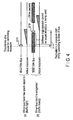
- the time at which the software trigger packet arrives at the camera apparatus varies (fluctuates) according to the condition of use of the IEEE 1394 bus (traffic condition of the bus band), as illustrated in FIG. 4 .
- This time fluctuation varies the accuracy of the exposure start timing, and thus the software trigger method has a problem of being inferior to the hardware trigger method in imaging performance.
- a camera control means of the hardware trigger method is used only in an IEEE 1394 camera system which requires exposure start timing of high accuracy, and a camera control means of the software trigger method, hardware connection of which is relatively easy, is used in an IEEE 1394 camera system which does not require exposure start timing of high accuracy.
- JP 2005 130 030 describes a mobile phone that can act as a master mobile phone by sending execution requests to a plurality of slave mobile phones.
- the execution request code comprises photographing time information so that at this photographing time the slave mobile phones all take a photo at the same time.
- JP 2006 203 817 discloses a camera according to the preamble of claim 1.
- a problem that may occur with these kinds of cameras is that the time delay can be rather long.
- a camera control means of the hardware trigger method requires a connection interface for the external trigger signal transmission path between the host device and the camera apparatus in addition to the IEEE 1394 interface, and has the problem of complicating the connection interface between the host device and the camera apparatus.
- the time at which a software trigger packet arrives at the camera apparatus varies (fluctuates) according to the bus use condition (traffic condition of the bus band), and thus the software trigger method has the problem that the accuracy of the exposure start timing varies, and the imaging performance is inferior to the hardware trigger method.
- the present invention has been made in consideration of the above circumstances.
- the object of the present invention is to provide a camera apparatus which has a random trigger function of a software trigger method, which can realize a trigger function of high timing accuracy while easy connection of the software trigger method is maintained.
- the present invention is a camera apparatus which includes a random trigger function of controlling exposure timing of an image sensor, based on timestamp information that is included in a software trigger packet received through an IEEE 1394 bus, comprising: a cycle timer operation circuit which outputs a cycle timer value that is synchronized with operation of the IEEE 1394 bus; an IEEE 1394 packet reception circuit which receives a packet on the IEEE 1394 bus; a software trigger detection circuit which detects the software trigger packet from the packet received by the IEEE 1394 packet reception circuit; a fixed delay value setting means which outputs a fixed delay value to perform a fixed trigger delay for the timestamp information included in the software trigger packet that is detected by the software trigger detection circuit; and an exposure control means which receives the cycle timer value, the timestamp information, and the fixed delay value, and instructs the image sensor to start exposure when the cycle timer value exceeds a value which is obtained by adding the fixed delay value to the timestamp information.
- the present invention is an IEEE 1394 camera system which connects a host device to a camera apparatus including an imaging element through an IEEE 1394 bus, wherein the host device includes a software trigger packet generation means which transmits a software trigger packet, when a phenomenon for which exposure is to be performed occurs, to the IEEE 1394 bus, the software packet includes a cycle timer value at the time the phenomenon occurs as a timestamp,
- the camera apparatus comprises: an IEEE 1394 interface which includes a cycle timer operation circuit that outputs a cycle timer value synchronized with the IEEE 1394 bus, and a software trigger packet detection means that detects the software trigger packet, a fixed delay setting means which outputs a fixed delay value determined with the unit of IEEE 1394 clock to perform a fixed trigger delay for the timestamp included in the software trigger packet detected by the software trigger packet detection means; and a trigger delay control means which receives the clock cycle timer value output from the cycle timer operation circuit, the timestamp output from the software trigger packet detection means, and the clock fixed delay value output from the fixed delay setting
- a camera apparatus which includes a random trigger function achieved by a software trigger method
- a camera apparatus is used as a factory automation (FA) camera or a machine vision camera.
- the camera apparatus is connected to an IEEE 1394 bus, and exposure of the camera apparatus is controlled by a host device (hereinafter referred to as a "host PC") through the IEEE 1394 bus.
- a host PC a host device
- the IEEE 1394 camera system to which the camera apparatus according to the embodiment of the present invention is connected, comprises a host PC 1, an IEEE 1394 bus 3, and a camera apparatus 10.
- FIG. 5 illustrates only one camera apparatus 10 which is connected to the IEEE 1394 bus 3 and to be controlled by the host PC 1, a plurality of camera apparatuses can be connected to the system.
- the host PC 1 includes a software trigger packet generation means 2. When a phenomenon for which exposure is to be performed occurs, the host PC 1 generates a software trigger packet (STP) by the software trigger packet generation means 2 each time when the phenomenon occurs, and transmits the packet to the IEEE 1394 bus 3.
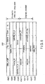
- FIG. 6 illustrates a structure of the software trigger packet (STP).
- the software trigger packet (STP) which is generated and issued by the software trigger packet generation means 2 each time a phenomenon for which exposure is to be performed occurs conforms to the Global Asynchronous Stream Packet defined by IEEE std 1394a-2000, as illustrated in FIG. 6 .
- the item “tag” is fixed to 0x3 by the standard.
- the item “channel” designates a channel which is used for data communication.
- the item “tcode”, in which generally 31 (0x1F) is described, is fixed to 0xA by the standard.
- the item “sy” is fixed to 0x0 by the standard.
- the item “header_CRC” describes CRC-32 of the header part.
- the item “source_ID” describes an ID of a node which issues a software trigger, such as the host PC.
- the item “specifier_ID_hi/lo” describes an organizationally unique identifier (OUI) of 24 bits.
- the item “version” indicates a version of the packet structure.
- a part following the above data defining part is a data defining part which defines a software trigger packet (STP) applied to the embodiment of the present invention.
- the item “reserved” indicates a reserved field.
- the item “destination_ID” indicates a node ID of the camera apparatus 10 according to the embodiment.
- timestamp describes a cycle timer value at the time when a cause for exposure occurs.
- command_soft_trig describes a unique code which indicates that the packet is a software trigger packet.
- data_CRC describes CRC-32 of a data part including the header_CRC and subsequent items.
- the cycle timer value of a clock defined by IEEE 1394 and described in the above item “timestamp” is recognized as timestamp information in the camera apparatus 10.
- the camera apparatus 10 which receives the software trigger packet (STP) includes an IEEE 1394 interface, and includes a cycle timer operation circuit (not shown: see FIG. 1 ) and a software trigger packet detection means 4 in the interface.
- the camera apparatus 10 also includes a fixed delay setting means 5, a trigger delay control means 6, and an imaging circuit 7 which includes an image sensor.
- the software trigger packet detection means 4 analyzes a packet on the IEEE 1394 bus 3, detects a software trigger packet (STP) from a code described in the item "command_soft_trig" of the packet. Then, the software trigger packet detection means 4 recognizes a cycle timer value of a clock described in the item "timestamp” of the packet as timestamp information, and transmits the timestamp information to the trigger delay control means 6.
- STP software trigger packet
- the fixed delay setting means 5 outputs a fixed delay value of the clock to perform fixed trigger delay for the timestamp information (cycle timer value described in the item "timestamp") which is included in the software trigger packet (STP) detected by the software trigger packet detection means 4.
- the fixed delay value the fixed delay setting means 5 stores in advance a value of a clock timing according to a clock frequency provided in IEEE 1394, which indicates a desired delay time which is larger than the maximum value of a time width (time fluctuation range) that is caused by shift of reception timing of the software trigger packet (STP) due to traffic fluctuations (bus band traffic degree) of the IEEE 1394 bus 3.
- the trigger delay control means 6 receives the cycle timer value of a clock which is output from the cycle timer operation circuit in the IEEE 1394 interface, the timestamp information (cycle timer value of a clock at the time when a cause for exposure occurs) output from the software trigger packet detection means 4, and the clock fixed delay value output from the fixed delay setting means, and compares the cycle timer value with the timestamp information for each clock. When the cycle timer value exceeds the timestamp information, the trigger delay control means 6 instructs the image sensor of the imaging circuit 7 to start exposure, after the fixed trigger delay time according to the fixed delay value has passed.
- the imaging circuit 7 obtains image data by controlling the image sensor in accordance with the instruction to start exposure. After exposure is finished, the imaging circuit 7 converts the image data obtained from the image sensor into an IEEE 1394 packet, and transmits the packet to the IEEE 1394 bus 3.
- FIG. 3 (a) and FIG. 3 (b) illustrate an exposure control timing of the camera apparatus 10 in the above embodiment.
- FIG. 4 (a) and FIG. 4 (b) illustrate an exposure control timing of a camera apparatus according to a conventional software trigger method.
- Each of FIG. 3 (a) and FIG. 4 (a) illustrates exposure control timing in the case where the bus band of the IEEE 1394 bus 3 has spare capacity (traffic is light), and each of FIG. 3 (b) and FIG. 4 (b) illustrates exposure control timing in the case where the bus band of the IEEE 1394 bus 3 is congested (traffic is heavy).
- exposure control it is possible to constantly perform exposure control at fixed timing according to a fixed delay value, regardless of the state of use of the IEEE 1394 bus, for occurrence of a cause for performing exposure (exposure instruction at desired exposure timing).
- a cause for performing exposure exposure instruction at desired exposure timing.
- a camera system which has a software trigger function with exposure timing of high accuracy.
- the IEEE 1394 camera system including the above camera apparatus 10, it is possible to perform exposure control at constantly fixed timing for occurrence of a phenomenon, for which exposure is to be performed, regardless of the state of use of the IEEE 1394 bus.
- the fixed delay setting means 5 provided in the camera apparatus 10 can set a desired delay time (delay time with the unit of clock) for each camera apparatus, it is also possible to perform direct control of the exposure start timing including a delay of a fixed time by the host PC 1, by adding clock delay information, or clock timestamp information which corresponds to desired exposure start in view of a fixed delay, to the software trigger packet (STP).
- STP software trigger packet
- FIG. 1 illustrates the structure of the camera apparatus 10
- FIG. 2 illustrates a structure of a trigger delay control circuit 12 provided in the camera apparatus 10.
- the camera apparatus 10 comprises an IEEE 1394 interface control circuit 11, a trigger delay control circuit 12, a synchronization signal generation circuit 13, an image sensor control circuit 14, an image sensor 15, and a CPU 16.
- the software trigger packet detection means 4 is realized by an IEEE 1394 packet reception circuit 111 and a software trigger detection circuit 114 which are included in the IEEE 1394 interface control circuit 11 illustrated in FIG. 1
- the fixed delay setting means 5 is realized by the CPU 16 also illustrated in FIG. 1
- the trigger delay control means 6 is realized by a cycle timer operation circuit 113 and the trigger delay control circuit 12 also illustrated in FIG. 1
- the imaging circuit 7 is realized by the synchronization signal generation circuit 13, the image sensor control circuit 14, and the image sensor 15 also illustrated in FIG. 1 .
- the IEEE 1394 interface circuit 11 manages control of IEEE 1394 packets which are transmitted and received through the IEEE 1394 bus 3.
- the IEEE 1394 interface circuit 11 includes the IEEE 1394 packet reception circuit 111, the IEEE 1394 packet transmission circuit 112, the cycle timer operation circuit 113, and the software trigger detection circuit 114.
- the IEEE 1394 packet reception circuit 111 has a packet reception processing function of monitoring the IEEE 1394 bus 3 and receiving packets on the bus.
- the IEEE 1394 packet transmission circuit 112 has a packet transmission processing function of transmitting packets to the IEEE 1394 bus 3.
- the cycle timer operation circuit 113 has a processing function of performing counting with the unit of clock provided in IEEE 1394 in synchronization with a cycle start packet on the IEEE 1394 bus 3, which is received by the IEEE 1394 packet reception circuit 111, and transmitting the cycle timer value which is updated for each clock to the trigger delay control circuit 12.
- the software trigger detection circuit 114 has a processing function of detecting a software trigger packet (STP) among packets on the IEEE 1394 bus 3 which are received by the IEEE 1394 packet reception circuit 111, obtaining timestamp information (cycle timer value at the time of occurrence of a phenomenon, for which exposure is to be performed) from the software trigger packet (STP), and transmitting the timestamp information to the trigger delay control circuit 12 in addition to notification of software trigger reception.
- STP software trigger packet
- the trigger delay control circuit 12 generates a trigger signal which issues an instruction to start exposure, based on the cycle timer value that is output from the cycle timer operation circuit 113 in response to notification of software trigger reception from the software trigger detection circuit 114, the timestamp information obtained by the software trigger detection circuit 114, and a fixed delay value issued by the CPU 16. As illustrated in FIG. 2 , the trigger delay control circuit 12 includes an adder 121 and a comparator 122.
- the adder 121 has a processing function of adding the clock fixed delay value 203 issued by the CPU 16 to the clock timestamp information 202 obtained by the software trigger detection circuit 114, and outputting a timestamp 204 including a trigger delay of a fixed time.
- the comparator 122 has a processing function of comparing the cycle timer value 201 output from the cycle timer operation circuit 113 with the timestamp 204 which is output from the adder 121 and includes the trigger delay of the fixed time, and outputting a trigger signal 205 which instructs the image sensor to start exposure when the cycle timer value 201 exceeds the timestamp 204 including the trigger delay of the fixed time.
- the comparator 122 performs comparison including overflow processing at a turning point of the cycle timer.
- the synchronization signal generation circuit 13 has a processing function of generating and outputting an exposure timing signal which is synchronized with the clock cycle, in response to the trigger signal output from the trigger delay control circuit 12.
- the image sensor control circuit 14 has a processing function of controlling exposure of the image sensor 15 based on the exposure timing signal output from the synchronization signal generation circuit 13, obtaining image data from the image sensor 15, converting the obtained image data into a packet with finishing of exposure, and transmitting the packet to the IEEE 1394 packet transmission circuit 112.
- Operation of the image sensor 15 is controlled by the image sensor control circuit 14, based on the synchronization signal generated by the synchronization signal generation circuit 13.
- the image sensor 15 outputs image data, which is imaged by an optical system (not shown), to the image sensor control circuit 14.
- the image sensor 15 is formed of an area image sensor such as a CMOS sensor and a CCD sensor.
- the CPU 16 manages control of the whole camera apparatus 10.
- the CPU 16 has a function of the fixed delay setting means 5 illustrated in FIG. 5 .
- the CPU 16 has a function of managing a preset fixed delay value with the unit of clock for performing a fixed trigger delay for the timestamp information (cycle timer value described in the item "timestamp") included in the software trigger packet (STP), and transmitting the fixed delay value to the trigger delay control circuit 12 through an internal bus.
- the host PC 1 transmits a software trigger packet (STP) which includes a timestamp of the trigger occurrence time based on the cycle timer.
- STP software trigger packet
- the software trigger packet (STP) is input to the camera apparatus 10 through the IEEE 1394 bus 3.
- the IEEE 1394 packet reception circuit 111 provided in the IEEE 1394 interface control circuit 11 receives the packet on the IEEE 1394 bus 3.
- the software trigger detection circuit 114 analyzes the packet received by the IEEE 1394 packet reception circuit 111, and determines whether the received packet is a software trigger packet (STP) or not. In the present embodiment, the software trigger detection circuit 114 recognizes that the received packet is a software trigger packet (STP) from the code which is described in the item "command_soft_trig" illustrated in FIG. 6 , and detects a software trigger packet. The software trigger detection circuit 114 also obtains the timestamp information (cycle timer value at which a cause for exposure occurs) which is described in the item "timestamp” from the detected software trigger packet (STP), and transmits the timestamp information to the trigger delay control circuit 12 in addition to notification of software trigger reception.
- STP software trigger packet
- the trigger delay control circuit 12 In response to notification of trigger reception from the software trigger detection circuit 114, the trigger delay control circuit 12 generates a trigger signal which instructs the image sensor to start exposure, based on the cycle timer value output from the cycle timer operation circuit 113, the timestamp information obtained by the software trigger detection circuit 114, and the fixed delay value issued by the CPU 16. Specifically, the adder 121 provided in the trigger delay control circuit 12 adds the fixed delay value 203 which is determined in clocks and issued from the CPU 16 to the timestamp information 202 determined in clocks and obtained by the software trigger detection circuit 114, and outputs a timestamp 204 which includes a trigger delay of a fixed time.
- the comparator 122 compares the cycle timer value 201 which is output from the cycle timer operation circuit 113 with the timestamp 204 which is output from the adder 121 and includes the trigger delay of the fixed time. When the cycle timer value 201 exceeds the timestamp 204 including the trigger delay of the fixed time, the comparator 122 transmits a trigger signal 205 which instructs the image sensor to start exposure to the synchronization signal generation circuit 13.
- the synchronization signal generation circuit 13 In response to the instruction (trigger signal 205 to start exposure, the synchronization signal generation circuit 13 generates an exposure timing signal which is synchronized with the clock cycles, transmits the exposure timing signal to the image sensor control circuit 14, and notifies the image sensor control circuit 14 of exposure timing of the image sensor 15.
- the image sensor control circuit 14 Based on the exposure timing, the image sensor control circuit 14 performs control of exposure of the image sensor 15. After exposure is finished, the image sensor control circuit 14 converts image data obtained from the image sensor 15 into a form (packet) which can be transmitted through the IEEE 1394 bus 3, and transmits the packet to the IEEE 1394 packet transmission circuit 112. The IEEE 1394 packet transmission circuit 112 outputs the image data packet received from the image sensor control circuit 14 to the IEEE 1394 bus 3.
- FIG. 3 (a) and FIG. 3 (b) illustrate operation timing of the above exposure control.
- the host PC 1 When a cause for exposure (desired exposure timing) occurs, the host PC 1 generates a timestamp based on the value of the cycle timer at the point in time. Thereafter, the host PC 1 generates a software trigger packet (STP), to which the timestamp is added.
- STP software trigger packet
- the timing of issuing a software trigger packet (STP) fluctuates according to the operation (bus band) state of the IEEE 1394 bus 3, in the same manner as the case of adopting a conventional software trigger technique.
- the camera apparatus 10 which receives the software trigger packet (STP) can recognize the desired exposure timing, regardless of fluctuations in the issue timing. Thereby, the camera apparatus 10 can start exposure at timing with a fixed delay from the desired exposure timing.
- the present invention is not limited to the above embodiment, but can be carried out with modified constituent elements within a range not departing from the gist of the invention.
- the comparator 122 transmits a trigger signal 205 which instructs the image sensor to start exposure to the synchronization signal generation circuit 13, when the cycle timer value 201 exceeds the timestamp 204 which includes a trigger delay of a fixed time.
- the present invention is not limited to this structure, but the comparator 122 may perform processing of transmitting the trigger signal 205 which instructs the image sensor to start exposure to the synchronization signal generation circuit 13, when the cycle timer value 201 reaches the timestamp 204 which includes the trigger delay of the fixed time.
- the CPU 16 which manages control of the whole camera apparatus 10 manages a preset fixed delay value which is determined with the unit of clock
- the present invention is not limited to this structure, but may have a structure of providing each camera apparatus with hardware in which a desired fixed delay value is set.
- the host PC 1 directly controls the exposure start timing including a delay of a fixed time, by adding delay information for each clock, or timestamp information for each clock that corresponds to desired exposure start, to which a fixed delay is added, to the software trigger packet (STP).
- the software trigger packet is formed of a Global Asynchronous Stream Packet
- the present invention is not limited to it, but it is possible to use a packet which can be transmitted with timestamp information added to the software trigger, such as an asynchronous write request for data block packet.
- the present invention is not limited to the structure, but, for example, a software trigger generation device which is independent of the host PC and the camera apparatus may transmit the software trigger packet (STP).
- the present invention may have a structure in which the camera apparatus itself transmits the software trigger packet (STP), and performs exposure control for another camera which is connected to the same IEEE 1394 bus,
Landscapes
- Physics & Mathematics (AREA)
- General Physics & Mathematics (AREA)
- Engineering & Computer Science (AREA)
- Multimedia (AREA)
- Signal Processing (AREA)
- Studio Devices (AREA)
- Exposure Control For Cameras (AREA)
- Details Of Cameras Including Film Mechanisms (AREA)
- Information Transfer Systems (AREA)
Claims (3)
- Dispositif de prise de vue (10) incluant une fonction à déclenchement aléatoire de commande de synchronisation d'exposition d'un capteur d'image (15), en se basant sur des informations d'horodatage qui sont incluses dans un paquet de déclenchement logiciel reçu par l'intermédiaire d'un bus IEEE 1394 (3), comprenant :un circuit de fonctionnement de temporisateur cyclique (113) qui délivre en sortie une valeur du temporisateur cyclique qui est synchronisée avec le fonctionnement du bus IEEE 1394 (3) ;un circuit de réception de paquet IEEE 1394 (111) qui reçoit un paquet sur le bus IEEE 1394 (3) ;un circuit de détection de dispositif de déclenchement logiciel (114) qui détecte le paquet de déclenchement logiciel provenant du paquet reçu par le circuit de réception de paquet IEEE 1394 (111) ; etun moyen de commande d'exposition (12, 14) qui reçoit la valeur du temporisateur cyclique et les informations d'horodatage, et demande au capteur d'image (15) de démarrer l'exposition lorsque la valeur du temporisateur cyclique dépasse une valeur qui est obtenue en se basant sur les informations d'horodatage ;caractérisé en ce quele dispositif de prise de vue (10) comprend en outre un moyen de réglage de valeur de retard fixe (5, 16) qui délivre en sortie une valeur de retard fixe pour effectuer un retard de déclenchement fixe pour les informations d'horodatage incluses dans la partie fournie à l'origine du paquet de déclenchement logiciel qui est détecté par le circuit de détection de dispositif de déclenchement logiciel (114) ;le circuit de détection de dispositif de déclenchement logiciel (114) détecte le paquet de déclenchement logiciel d'après un code dans une partie fournie à l'origine du paquet reçu par le circuit de réception de paquet IEEE 1394 (111) ; etle moyen de commande d'exposition (12, 14) démarre l'exposition du capteur d'image (15) lorsque la valeur du temporisateur cyclique, les informations d'horodatage et la valeur de retard fixe sont reçues et lorsque la valeur du temporisateur cyclique dépasse une valeur qui est la somme de la valeur de retard fixe et des informations d'horodatage.
- Dispositif de prise de vue selon la revendication 1, caractérisé en ce que le moyen de réglage de valeur de retard fixe (5, 16) mémorise, en tant que valeur de retard fixe, la valeur du séquencement d'horloge qui indique un temps de retard désiré, qui est plus grande que la valeur d'une durée produite par les fluctuations de séquencement de réception du paquet de déclenchement logiciel, dues aux fluctuations du trafic (degré de trafic dans la bande de bus) du bus IEEE 1394 (3).
- Dispositif de prise de vue selon la revendication 1, caractérisé en ce que
le moyen de commande d'exposition (12, 14) comporte un circuit de commande de retard de déclenchement (12), un circuit de génération de signal de synchronisation (13) et un circuit de commande de capteur d'image (14),
le circuit de commande de retard de déclenchement (12) comporte un additionneur (121) qui additionne la valeur de retard fixe avec la valeur des informations d'horodatage, et un comparateur (122) qui compare la valeur des informations d'horodatage fournies en sortie par l'additionneur (121) avec la valeur du temporisateur cyclique et fournit en sortie un signal de déclenchement lorsque la valeur du temporisateur cyclique dépasse la valeur des informations d'horodatage, et
le circuit de génération de signal de synchronisation (13) notifie le circuit de commande de capteur d'image (14) de la synchronisation d'exposition du capteur d'image (7) en se basant sur le signal de déclenchement, et le circuit de commande de capteur d'image (14) commande l'exposition du capteur d'image (7) en réponse à la notification de synchronisation d'exposition.
Applications Claiming Priority (2)
| Application Number | Priority Date | Filing Date | Title |
|---|---|---|---|
| JP2010014754A JP5593078B2 (ja) | 2010-01-26 | 2010-01-26 | カメラ装置 |
| PCT/JP2010/052452 WO2011092869A1 (fr) | 2010-01-26 | 2010-02-18 | Dispositif de caméra |
Publications (3)
| Publication Number | Publication Date |
|---|---|
| EP2479979A1 EP2479979A1 (fr) | 2012-07-25 |
| EP2479979A4 EP2479979A4 (fr) | 2013-07-17 |
| EP2479979B1 true EP2479979B1 (fr) | 2015-05-13 |
Family
ID=44318877
Family Applications (1)
| Application Number | Title | Priority Date | Filing Date |
|---|---|---|---|
| EP20100844627 Not-in-force EP2479979B1 (fr) | 2010-01-26 | 2010-02-18 | Dispositif de caméra |
Country Status (7)
| Country | Link |
|---|---|
| US (1) | US8767077B2 (fr) |
| EP (1) | EP2479979B1 (fr) |
| JP (1) | JP5593078B2 (fr) |
| KR (1) | KR101396685B1 (fr) |
| CN (1) | CN102598654B (fr) |
| CA (1) | CA2777380C (fr) |
| WO (1) | WO2011092869A1 (fr) |
Families Citing this family (6)
| Publication number | Priority date | Publication date | Assignee | Title |
|---|---|---|---|---|
| JP5802727B2 (ja) | 2013-11-11 | 2015-10-28 | 東芝テリー株式会社 | 同期式カメラ |
| CN108307117B (zh) * | 2018-02-09 | 2020-03-10 | 湖南大学 | 全场光测多功能同步控制装置与方法 |
| US10698857B2 (en) * | 2018-09-28 | 2020-06-30 | Bristol, Inc | Systems, methods, and apparatus to synchronize data bus access |
| CN111551948B (zh) * | 2020-05-20 | 2022-08-16 | 炬佑智能科技(苏州)有限公司 | 一种tof设备的控制方法、计算机存储介质 |
| CN112738370B (zh) * | 2020-12-24 | 2022-04-05 | 凌云光技术股份有限公司 | 一种单张产品质量检测系统和方法 |
| JP7729966B1 (ja) * | 2024-11-13 | 2025-08-26 | 東芝テリー株式会社 | 検証支援機能を有したカメラ装置、検証支援装置、カメラ装置の検証支援方法 |
Family Cites Families (7)
| Publication number | Priority date | Publication date | Assignee | Title |
|---|---|---|---|---|
| US6005618A (en) | 1994-07-29 | 1999-12-21 | Sony Corporation | Image pick-up device with control circuit that provides a variable horizontal synchronizing signal |
| JP3787498B2 (ja) | 2001-02-13 | 2006-06-21 | キヤノン株式会社 | 撮像装置及び撮像システム |
| JP4370143B2 (ja) * | 2003-10-21 | 2009-11-25 | オリンパス株式会社 | 携帯電話機 |
| FI20031657A7 (fi) * | 2003-11-14 | 2005-05-15 | Nokia Corp | Langaton monikamerajärjestelmä |
| JP2006203817A (ja) * | 2005-01-24 | 2006-08-03 | Nippon Soken Inc | マルチカメラシステム |
| JP4983729B2 (ja) * | 2008-06-05 | 2012-07-25 | 株式会社島津製作所 | 撮影装置 |
| JP5517668B2 (ja) * | 2010-02-19 | 2014-06-11 | キヤノン株式会社 | 通信装置、撮像装置及びそれらの制御方法、プログラム並びに記憶媒体 |
-
2010
- 2010-01-26 JP JP2010014754A patent/JP5593078B2/ja not_active Expired - Fee Related
- 2010-02-18 KR KR1020127011891A patent/KR101396685B1/ko not_active Expired - Fee Related
- 2010-02-18 CN CN201080050728.5A patent/CN102598654B/zh not_active Expired - Fee Related
- 2010-02-18 CA CA2777380A patent/CA2777380C/fr not_active Expired - Fee Related
- 2010-02-18 EP EP20100844627 patent/EP2479979B1/fr not_active Not-in-force
- 2010-02-18 WO PCT/JP2010/052452 patent/WO2011092869A1/fr not_active Ceased
-
2012
- 2012-04-18 US US13/450,114 patent/US8767077B2/en not_active Expired - Fee Related
Also Published As
| Publication number | Publication date |
|---|---|
| JP5593078B2 (ja) | 2014-09-17 |
| US8767077B2 (en) | 2014-07-01 |
| CN102598654A (zh) | 2012-07-18 |
| JP2011155410A (ja) | 2011-08-11 |
| CA2777380C (fr) | 2015-05-05 |
| KR20120079142A (ko) | 2012-07-11 |
| CA2777380A1 (fr) | 2011-08-04 |
| EP2479979A4 (fr) | 2013-07-17 |
| CN102598654B (zh) | 2015-01-28 |
| WO2011092869A1 (fr) | 2011-08-04 |
| US20120200719A1 (en) | 2012-08-09 |
| EP2479979A1 (fr) | 2012-07-25 |
| KR101396685B1 (ko) | 2014-05-16 |
Similar Documents
| Publication | Publication Date | Title |
|---|---|---|
| EP2479979B1 (fr) | Dispositif de caméra | |
| US7945154B2 (en) | Information communication device and external device | |
| KR101589227B1 (ko) | 차량용 이더넷 통신망에서의 카메라 셔터 동기화 제어 방법 및 장치 | |
| US20120327950A1 (en) | Method for Transmitting Data Packets | |
| US11627388B2 (en) | Method and a monitoring camera | |
| US20170127363A1 (en) | Transmission system, wireless device, and synchronization establishment method | |
| EP3070926B1 (fr) | Caméra synchrone | |
| US9344375B2 (en) | Method for transmitting data packets between two communication modules and communication module for transmitting data packets, as well as communication module for receiving data packets | |
| KR102204954B1 (ko) | Can 컨트롤러 및 이를 이용한 데이터 전송 방법 | |
| US20250038946A1 (en) | Synchronized Control of Sensors in an Ethernet Network | |
| US9094911B2 (en) | Data communication system, method of optimizing preamble length, and communication apparatus | |
| US20150350329A1 (en) | Method and apparatus for transmitting sensor data in a wireless network | |
| US8818533B2 (en) | Information processing device, communication system, and information processing method | |
| US12563287B2 (en) | Local generation of commands to a vehicle sensor | |
| US12463916B2 (en) | Communication apparatus, control method for communication apparatus, and storage medium | |
| WO2013128943A1 (fr) | Dispositif de transmission sans fil, système sans fil, dispositif de transfert, et programme | |
| WO2023145479A1 (fr) | Dispositif de communication, procédé de communication, et programme | |
| EP4210288A1 (fr) | Commande synchronisée de capteurs dans un réseau ethernet | |
| JP5999138B2 (ja) | 無線通信アダプタ | |
| US12401490B2 (en) | Communication device and communication method | |
| JP5552898B2 (ja) | 撮影システム |
Legal Events
| Date | Code | Title | Description |
|---|---|---|---|
| PUAI | Public reference made under article 153(3) epc to a published international application that has entered the european phase |
Free format text: ORIGINAL CODE: 0009012 |
|
| 17P | Request for examination filed |
Effective date: 20120416 |
|
| AK | Designated contracting states |
Kind code of ref document: A1 Designated state(s): AT BE BG CH CY CZ DE DK EE ES FI FR GB GR HR HU IE IS IT LI LT LU LV MC MK MT NL NO PL PT RO SE SI SK SM TR |
|
| DAX | Request for extension of the european patent (deleted) | ||
| A4 | Supplementary search report drawn up and despatched |
Effective date: 20130614 |
|
| RIC1 | Information provided on ipc code assigned before grant |
Ipc: H04N 5/235 20060101ALI20130610BHEP Ipc: H04N 5/232 20060101AFI20130610BHEP |
|
| 17Q | First examination report despatched |
Effective date: 20140417 |
|
| GRAP | Despatch of communication of intention to grant a patent |
Free format text: ORIGINAL CODE: EPIDOSNIGR1 |
|
| INTG | Intention to grant announced |
Effective date: 20141119 |
|
| RIN1 | Information on inventor provided before grant (corrected) |
Inventor name: KISHI, JUNJI |
|
| GRAS | Grant fee paid |
Free format text: ORIGINAL CODE: EPIDOSNIGR3 |
|
| GRAA | (expected) grant |
Free format text: ORIGINAL CODE: 0009210 |
|
| AK | Designated contracting states |
Kind code of ref document: B1 Designated state(s): AT BE BG CH CY CZ DE DK EE ES FI FR GB GR HR HU IE IS IT LI LT LU LV MC MK MT NL NO PL PT RO SE SI SK SM TR |
|
| REG | Reference to a national code |
Ref country code: GB Ref legal event code: FG4D |
|
| REG | Reference to a national code |
Ref country code: CH Ref legal event code: EP |
|
| REG | Reference to a national code |
Ref country code: IE Ref legal event code: FG4D |
|
| REG | Reference to a national code |
Ref country code: AT Ref legal event code: REF Ref document number: 727182 Country of ref document: AT Kind code of ref document: T Effective date: 20150615 |
|
| REG | Reference to a national code |
Ref country code: DE Ref legal event code: R096 Ref document number: 602010024686 Country of ref document: DE Effective date: 20150625 |
|
| REG | Reference to a national code |
Ref country code: DE Ref legal event code: R082 Ref document number: 602010024686 Country of ref document: DE Representative=s name: GRAMM, LINS & PARTNER PATENT- UND RECHTSANWAEL, DE |
|
| REG | Reference to a national code |
Ref country code: NL Ref legal event code: T3 |
|
| REG | Reference to a national code |
Ref country code: AT Ref legal event code: MK05 Ref document number: 727182 Country of ref document: AT Kind code of ref document: T Effective date: 20150513 |
|
| REG | Reference to a national code |
Ref country code: LT Ref legal event code: MG4D |
|
| PG25 | Lapsed in a contracting state [announced via postgrant information from national office to epo] |
Ref country code: HR Free format text: LAPSE BECAUSE OF FAILURE TO SUBMIT A TRANSLATION OF THE DESCRIPTION OR TO PAY THE FEE WITHIN THE PRESCRIBED TIME-LIMIT Effective date: 20150513 Ref country code: LT Free format text: LAPSE BECAUSE OF FAILURE TO SUBMIT A TRANSLATION OF THE DESCRIPTION OR TO PAY THE FEE WITHIN THE PRESCRIBED TIME-LIMIT Effective date: 20150513 Ref country code: ES Free format text: LAPSE BECAUSE OF FAILURE TO SUBMIT A TRANSLATION OF THE DESCRIPTION OR TO PAY THE FEE WITHIN THE PRESCRIBED TIME-LIMIT Effective date: 20150513 Ref country code: NO Free format text: LAPSE BECAUSE OF FAILURE TO SUBMIT A TRANSLATION OF THE DESCRIPTION OR TO PAY THE FEE WITHIN THE PRESCRIBED TIME-LIMIT Effective date: 20150813 Ref country code: FI Free format text: LAPSE BECAUSE OF FAILURE TO SUBMIT A TRANSLATION OF THE DESCRIPTION OR TO PAY THE FEE WITHIN THE PRESCRIBED TIME-LIMIT Effective date: 20150513 Ref country code: PT Free format text: LAPSE BECAUSE OF FAILURE TO SUBMIT A TRANSLATION OF THE DESCRIPTION OR TO PAY THE FEE WITHIN THE PRESCRIBED TIME-LIMIT Effective date: 20150914 |
|
| PG25 | Lapsed in a contracting state [announced via postgrant information from national office to epo] |
Ref country code: LV Free format text: LAPSE BECAUSE OF FAILURE TO SUBMIT A TRANSLATION OF THE DESCRIPTION OR TO PAY THE FEE WITHIN THE PRESCRIBED TIME-LIMIT Effective date: 20150513 Ref country code: BG Free format text: LAPSE BECAUSE OF FAILURE TO SUBMIT A TRANSLATION OF THE DESCRIPTION OR TO PAY THE FEE WITHIN THE PRESCRIBED TIME-LIMIT Effective date: 20150813 Ref country code: GR Free format text: LAPSE BECAUSE OF FAILURE TO SUBMIT A TRANSLATION OF THE DESCRIPTION OR TO PAY THE FEE WITHIN THE PRESCRIBED TIME-LIMIT Effective date: 20150814 Ref country code: IS Free format text: LAPSE BECAUSE OF FAILURE TO SUBMIT A TRANSLATION OF THE DESCRIPTION OR TO PAY THE FEE WITHIN THE PRESCRIBED TIME-LIMIT Effective date: 20150913 Ref country code: AT Free format text: LAPSE BECAUSE OF FAILURE TO SUBMIT A TRANSLATION OF THE DESCRIPTION OR TO PAY THE FEE WITHIN THE PRESCRIBED TIME-LIMIT Effective date: 20150513 |
|
| REG | Reference to a national code |
Ref country code: FR Ref legal event code: PLFP Year of fee payment: 7 |
|
| PG25 | Lapsed in a contracting state [announced via postgrant information from national office to epo] |
Ref country code: EE Free format text: LAPSE BECAUSE OF FAILURE TO SUBMIT A TRANSLATION OF THE DESCRIPTION OR TO PAY THE FEE WITHIN THE PRESCRIBED TIME-LIMIT Effective date: 20150513 Ref country code: DK Free format text: LAPSE BECAUSE OF FAILURE TO SUBMIT A TRANSLATION OF THE DESCRIPTION OR TO PAY THE FEE WITHIN THE PRESCRIBED TIME-LIMIT Effective date: 20150513 |
|
| REG | Reference to a national code |
Ref country code: DE Ref legal event code: R097 Ref document number: 602010024686 Country of ref document: DE |
|
| PG25 | Lapsed in a contracting state [announced via postgrant information from national office to epo] |
Ref country code: PL Free format text: LAPSE BECAUSE OF FAILURE TO SUBMIT A TRANSLATION OF THE DESCRIPTION OR TO PAY THE FEE WITHIN THE PRESCRIBED TIME-LIMIT Effective date: 20150513 Ref country code: SK Free format text: LAPSE BECAUSE OF FAILURE TO SUBMIT A TRANSLATION OF THE DESCRIPTION OR TO PAY THE FEE WITHIN THE PRESCRIBED TIME-LIMIT Effective date: 20150513 Ref country code: RO Free format text: LAPSE BECAUSE OF NON-PAYMENT OF DUE FEES Effective date: 20150513 Ref country code: CZ Free format text: LAPSE BECAUSE OF FAILURE TO SUBMIT A TRANSLATION OF THE DESCRIPTION OR TO PAY THE FEE WITHIN THE PRESCRIBED TIME-LIMIT Effective date: 20150513 |
|
| PLBE | No opposition filed within time limit |
Free format text: ORIGINAL CODE: 0009261 |
|
| STAA | Information on the status of an ep patent application or granted ep patent |
Free format text: STATUS: NO OPPOSITION FILED WITHIN TIME LIMIT |
|
| 26N | No opposition filed |
Effective date: 20160216 |
|
| PG25 | Lapsed in a contracting state [announced via postgrant information from national office to epo] |
Ref country code: IT Free format text: LAPSE BECAUSE OF FAILURE TO SUBMIT A TRANSLATION OF THE DESCRIPTION OR TO PAY THE FEE WITHIN THE PRESCRIBED TIME-LIMIT Effective date: 20150513 |
|
| PG25 | Lapsed in a contracting state [announced via postgrant information from national office to epo] |
Ref country code: SI Free format text: LAPSE BECAUSE OF FAILURE TO SUBMIT A TRANSLATION OF THE DESCRIPTION OR TO PAY THE FEE WITHIN THE PRESCRIBED TIME-LIMIT Effective date: 20150513 |
|
| PG25 | Lapsed in a contracting state [announced via postgrant information from national office to epo] |
Ref country code: LU Free format text: LAPSE BECAUSE OF FAILURE TO SUBMIT A TRANSLATION OF THE DESCRIPTION OR TO PAY THE FEE WITHIN THE PRESCRIBED TIME-LIMIT Effective date: 20160218 Ref country code: MC Free format text: LAPSE BECAUSE OF FAILURE TO SUBMIT A TRANSLATION OF THE DESCRIPTION OR TO PAY THE FEE WITHIN THE PRESCRIBED TIME-LIMIT Effective date: 20150513 |
|
| REG | Reference to a national code |
Ref country code: CH Ref legal event code: PL |
|
| GBPC | Gb: european patent ceased through non-payment of renewal fee |
Effective date: 20160218 |
|
| PG25 | Lapsed in a contracting state [announced via postgrant information from national office to epo] |
Ref country code: CH Free format text: LAPSE BECAUSE OF NON-PAYMENT OF DUE FEES Effective date: 20160229 Ref country code: LI Free format text: LAPSE BECAUSE OF NON-PAYMENT OF DUE FEES Effective date: 20160229 |
|
| REG | Reference to a national code |
Ref country code: IE Ref legal event code: MM4A |
|
| REG | Reference to a national code |
Ref country code: FR Ref legal event code: PLFP Year of fee payment: 8 |
|
| PG25 | Lapsed in a contracting state [announced via postgrant information from national office to epo] |
Ref country code: IE Free format text: LAPSE BECAUSE OF NON-PAYMENT OF DUE FEES Effective date: 20160218 Ref country code: GB Free format text: LAPSE BECAUSE OF NON-PAYMENT OF DUE FEES Effective date: 20160218 |
|
| PG25 | Lapsed in a contracting state [announced via postgrant information from national office to epo] |
Ref country code: SE Free format text: LAPSE BECAUSE OF FAILURE TO SUBMIT A TRANSLATION OF THE DESCRIPTION OR TO PAY THE FEE WITHIN THE PRESCRIBED TIME-LIMIT Effective date: 20150513 |
|
| PG25 | Lapsed in a contracting state [announced via postgrant information from national office to epo] |
Ref country code: MT Free format text: LAPSE BECAUSE OF FAILURE TO SUBMIT A TRANSLATION OF THE DESCRIPTION OR TO PAY THE FEE WITHIN THE PRESCRIBED TIME-LIMIT Effective date: 20150513 |
|
| REG | Reference to a national code |
Ref country code: FR Ref legal event code: PLFP Year of fee payment: 9 |
|
| PG25 | Lapsed in a contracting state [announced via postgrant information from national office to epo] |
Ref country code: CY Free format text: LAPSE BECAUSE OF FAILURE TO SUBMIT A TRANSLATION OF THE DESCRIPTION OR TO PAY THE FEE WITHIN THE PRESCRIBED TIME-LIMIT Effective date: 20150513 Ref country code: SM Free format text: LAPSE BECAUSE OF FAILURE TO SUBMIT A TRANSLATION OF THE DESCRIPTION OR TO PAY THE FEE WITHIN THE PRESCRIBED TIME-LIMIT Effective date: 20150513 Ref country code: HU Free format text: LAPSE BECAUSE OF FAILURE TO SUBMIT A TRANSLATION OF THE DESCRIPTION OR TO PAY THE FEE WITHIN THE PRESCRIBED TIME-LIMIT; INVALID AB INITIO Effective date: 20100218 |
|
| PG25 | Lapsed in a contracting state [announced via postgrant information from national office to epo] |
Ref country code: MT Free format text: LAPSE BECAUSE OF FAILURE TO SUBMIT A TRANSLATION OF THE DESCRIPTION OR TO PAY THE FEE WITHIN THE PRESCRIBED TIME-LIMIT Effective date: 20160229 Ref country code: MK Free format text: LAPSE BECAUSE OF FAILURE TO SUBMIT A TRANSLATION OF THE DESCRIPTION OR TO PAY THE FEE WITHIN THE PRESCRIBED TIME-LIMIT Effective date: 20150513 Ref country code: TR Free format text: LAPSE BECAUSE OF FAILURE TO SUBMIT A TRANSLATION OF THE DESCRIPTION OR TO PAY THE FEE WITHIN THE PRESCRIBED TIME-LIMIT Effective date: 20150513 |
|
| PGFP | Annual fee paid to national office [announced via postgrant information from national office to epo] |
Ref country code: NL Payment date: 20190214 Year of fee payment: 10 |
|
| PGFP | Annual fee paid to national office [announced via postgrant information from national office to epo] |
Ref country code: FR Payment date: 20190110 Year of fee payment: 10 Ref country code: DE Payment date: 20190228 Year of fee payment: 10 |
|
| PGFP | Annual fee paid to national office [announced via postgrant information from national office to epo] |
Ref country code: BE Payment date: 20190129 Year of fee payment: 10 |
|
| REG | Reference to a national code |
Ref country code: DE Ref legal event code: R119 Ref document number: 602010024686 Country of ref document: DE |
|
| REG | Reference to a national code |
Ref country code: NL Ref legal event code: MM Effective date: 20200301 |
|
| REG | Reference to a national code |
Ref country code: BE Ref legal event code: MM Effective date: 20200229 |
|
| PG25 | Lapsed in a contracting state [announced via postgrant information from national office to epo] |
Ref country code: NL Free format text: LAPSE BECAUSE OF NON-PAYMENT OF DUE FEES Effective date: 20200301 |
|
| PG25 | Lapsed in a contracting state [announced via postgrant information from national office to epo] |
Ref country code: FR Free format text: LAPSE BECAUSE OF NON-PAYMENT OF DUE FEES Effective date: 20200229 Ref country code: DE Free format text: LAPSE BECAUSE OF NON-PAYMENT OF DUE FEES Effective date: 20200901 |
|
| PG25 | Lapsed in a contracting state [announced via postgrant information from national office to epo] |
Ref country code: BE Free format text: LAPSE BECAUSE OF NON-PAYMENT OF DUE FEES Effective date: 20200229 |