EP2480148B1 - Système de tige vertébrale composite - Google Patents
Système de tige vertébrale composite Download PDFInfo
- Publication number
- EP2480148B1 EP2480148B1 EP10768832.7A EP10768832A EP2480148B1 EP 2480148 B1 EP2480148 B1 EP 2480148B1 EP 10768832 A EP10768832 A EP 10768832A EP 2480148 B1 EP2480148 B1 EP 2480148B1
- Authority
- EP
- European Patent Office
- Prior art keywords
- section
- modulus
- vertebral rod
- elasticity
- intermediate section
- Prior art date
- Legal status (The legal status is an assumption and is not a legal conclusion. Google has not performed a legal analysis and makes no representation as to the accuracy of the status listed.)
- Not-in-force
Links
Images


Classifications
-
- A—HUMAN NECESSITIES
- A61—MEDICAL OR VETERINARY SCIENCE; HYGIENE
- A61B—DIAGNOSIS; SURGERY; IDENTIFICATION
- A61B17/00—Surgical instruments, devices or methods
- A61B17/56—Surgical instruments or methods for treatment of bones or joints; Devices specially adapted therefor
- A61B17/58—Surgical instruments or methods for treatment of bones or joints; Devices specially adapted therefor for osteosynthesis, e.g. bone plates, screws or setting implements
- A61B17/68—Internal fixation devices, including fasteners and spinal fixators, even if a part thereof projects from the skin
- A61B17/70—Spinal positioners or stabilisers, e.g. stabilisers comprising fluid filler in an implant
- A61B17/7001—Screws or hooks combined with longitudinal elements which do not contact vertebrae
- A61B17/7002—Longitudinal elements, e.g. rods
- A61B17/7019—Longitudinal elements having flexible parts, or parts connected together, such that after implantation the elements can move relative to each other
- A61B17/7026—Longitudinal elements having flexible parts, or parts connected together, such that after implantation the elements can move relative to each other with a part that is flexible due to its form
-
- A—HUMAN NECESSITIES
- A61—MEDICAL OR VETERINARY SCIENCE; HYGIENE
- A61B—DIAGNOSIS; SURGERY; IDENTIFICATION
- A61B17/00—Surgical instruments, devices or methods
- A61B17/56—Surgical instruments or methods for treatment of bones or joints; Devices specially adapted therefor
- A61B17/58—Surgical instruments or methods for treatment of bones or joints; Devices specially adapted therefor for osteosynthesis, e.g. bone plates, screws or setting implements
- A61B17/68—Internal fixation devices, including fasteners and spinal fixators, even if a part thereof projects from the skin
- A61B17/70—Spinal positioners or stabilisers, e.g. stabilisers comprising fluid filler in an implant
- A61B17/7001—Screws or hooks combined with longitudinal elements which do not contact vertebrae
- A61B17/7002—Longitudinal elements, e.g. rods
- A61B17/7011—Longitudinal element being non-straight, e.g. curved, angled or branched
-
- A—HUMAN NECESSITIES
- A61—MEDICAL OR VETERINARY SCIENCE; HYGIENE
- A61B—DIAGNOSIS; SURGERY; IDENTIFICATION
- A61B17/00—Surgical instruments, devices or methods
- A61B17/56—Surgical instruments or methods for treatment of bones or joints; Devices specially adapted therefor
- A61B17/58—Surgical instruments or methods for treatment of bones or joints; Devices specially adapted therefor for osteosynthesis, e.g. bone plates, screws or setting implements
- A61B17/68—Internal fixation devices, including fasteners and spinal fixators, even if a part thereof projects from the skin
- A61B17/70—Spinal positioners or stabilisers, e.g. stabilisers comprising fluid filler in an implant
- A61B17/7001—Screws or hooks combined with longitudinal elements which do not contact vertebrae
- A61B17/7002—Longitudinal elements, e.g. rods
- A61B17/7019—Longitudinal elements having flexible parts, or parts connected together, such that after implantation the elements can move relative to each other
- A61B17/7031—Longitudinal elements having flexible parts, or parts connected together, such that after implantation the elements can move relative to each other made wholly or partly of flexible material
-
- A—HUMAN NECESSITIES
- A61—MEDICAL OR VETERINARY SCIENCE; HYGIENE
- A61B—DIAGNOSIS; SURGERY; IDENTIFICATION
- A61B90/00—Instruments, implements or accessories specially adapted for surgery or diagnosis and not covered by any of the groups A61B1/00 - A61B50/00, e.g. for luxation treatment or for protecting wound edges
- A61B90/03—Automatic limiting or abutting means, e.g. for safety
- A61B2090/033—Abutting means, stops, e.g. abutting on tissue or skin
- A61B2090/034—Abutting means, stops, e.g. abutting on tissue or skin abutting on parts of the device itself
Definitions
- the invention relates to a vertebral rod according to the preamble of claim 1.
- a vertebral rod of the initially-mentioned type is known, e.g., from WO 2008/000944 A2 .
- Further spinal rods are known, e.g., from US 2007/0191832 A , US 2006/0247638 A1 , US 2006/0229608 A1 , and US 2008/0177320 A1 .
- Spinal disorders such as degenerative disc disease, disc herniation, osteoporosis, spondylolisthesis, stenosis, scoliosis and other curvature abnormalities, kyphosis, tumor, and fracture may result from factors including tiauma, disease and degenerative conditions caused by injury and aging. Spinal disorders typically result in symptoms including pain, nerve damage, and partial or complete loss of mobility.
- Non-surgical treatments such as medication, rehabilitation and exercise can be effective, however, may fail to relieve the symptoms associated with these disorders.
- Surgical treatment of these spinal disorders include discectomy, laminectomy, fusion and implantable prosthetics.
- connecting elements such as vertebral rods ate often used to provide stability to a treated region.
- one or more rods may be attached to the exterior of two or more vertebral members.
- Rods redirect stresses away from, a damaged or defective region while healing takes place to restore proper alignment and generally support the vertebral members.
- rods are attached to the vertebral members without the use of implants or spinal fusion.
- Flexible connecting elements are also known that permit limited spinal motion of a spinal motion segment. Such flexible connecting elements can provide dynamic spinal support. While prior connecting elements have attempted to provide effective spinal stabilization, there remains a need for connecting elements that provide a dynamic stabilizing resistance to forces and permit motion of a spinal column segment(s) in flexion and extension while effectively stabilizing the spinal column segment(s) and the structural integrity of the connecting elements.
- a dynamic vertebral rod system having flexion and extension capability, which provides stability while reducing stress on spinal elements.
- the vertebral rod system can include a configuration to provide increased strength and stiffness to the rod while maintaining flexibility at selected portions of the rod. It is envisioned that the disclosed system may be employed as a posterior, anterior and/or lateral dynamic stabilization device. The components of the vertebral rod system are easily manufactured and assembled.
- the invention provides a vertebral rod according to claim 1.
- the intermediate section includes a reinforcement portion having a modulus of elasticity that is greater than the third modulus.
- the third material is an outer layer disposed about the reinforcement portion.
- the reinforcement portion of the intermediate section can have an arcuate configuration. The reinforcement portion may connect the first material and the second material such that the first, second and intermediate sections are in a continuous reinforcement configuration of the vertebral rod.
- the second section may include an elongated core formed of a material having a modulus of elasticity that is less than the second modulus.
- the second material is an outer layer disposed about the core of the second section.
- the first material can be an elongated core having a cross section extending from a first end of the first section to the inner surface of the intermediate section.
- the core cross section comprises an outer diameter of the first section adjacent the first end and including a tapered portion with a reduced diameter, relative to the outer diameter, adjacent the inner surface.
- the second material may be an elongated core having a cross section extending from a first end of the second section to the inner surface of the intermediate section.
- the core cross section of the second section comprises an outer diameter of the second section adjacent the first end of the second section and including a tapered portion with a reduced diameter, relative to the outer diameter of the second section, adjacent the inner surface.
- the reinforcement portion of the intermediate section may be arcuately disposed about the inner surface and having a first end, the first end being spaced apart from the first material.
- the reinforcement portion of the intermediate section may have a second end that is spaced apart from the second material.
- the second intermediate section may include at least one lateral protuberance.
- the vertebral rod includes a first elongated section including an elongated core and an outer layer disposed about the core. At least one of the core and the outer layer are formed of a first material having a modulus of elasticity greater than 30 gigapascal (GPa). The other of the core and the outer layer is formed of a second material having a modulus of elasticity less than 20GPa.
- a second elongated section includes an elongated core and an outer layer disposed about the core of the second section. At least one of the core of the second section and the outer layer is formed of the first material. The other of the core and the outer layer of the second section is formed of the second material.
- An intermediate section is disposed between the first section and the second section, and is formed of the second material. The intermediate section has an arcuate inner surface that defines a cavity and an open end of the intermediate section.
- the vertebral rod includes a third elongated section including a fourth material having a fourth modulus of elasticity.
- a second flexible intermediate section is disposed between the second section and the third section. The fourth modulus is greater than the third modulus.
- Figs. 1-7 , 11 , 15-17 , 21-23 , and 25-29 do not form embodiments of the invention as such, but help explaining aspects of the invention.
- the exemplary embodiments of the vertebral rod system and methods of use disclosed are discussed in terms of medical devices for the treatment of spinal disorders and more particularly, in terms of a dynamic vertebral rod system having flexion and extension capability. It is envisioned that the vertebral rod system and methods of use disclosed provide stability and maintains structural integrity while reducing stress on spinal elements. It is envisioned that the present disclosure may be employed to treat spinal disorders such as, for example, degenerative disc disease, disc herniation, osteoporosis, spondylolisthesis, stenosis, scoliosis and other curvature abnormalities, kyphosis, tumor and fractures.
- spinal disorders such as, for example, degenerative disc disease, disc herniation, osteoporosis, spondylolisthesis, stenosis, scoliosis and other curvature abnormalities, kyphosis, tumor and fractures.
- the present disclosure may be employed with surgical treatments including open surgery and minimally invasive procedures, of such disorders, such as, for example, discectomy, laminectomy, fusion, bone graft and implantable prosthetics. It is contemplated that the present disclosure may be employed with other osteal and bone related applications, including those associated with diagnostics and therapeutics. It is further contemplated that the disclosed vertebral rod system may be employed in a surgical treatment with a patient in a prone or supine position, employing a posterior, lateral or anterior approach. The present disclosure may be employed with procedures for treating the lumbar, cervical, thoracic and pelvic regions of a spinal column.
- Ranges may be expressed herein as from “about” or “approximately” one particular value and/or to “about” or “approximately” another particular value. When such a range is expressed, another embodiment includes from the one particular value and/or to the other particular value. Similarly, when values are expressed as approximations, by use of the antecedent "about,” it will be understood that the particular value forms another embodiment.
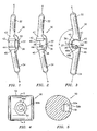
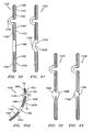
- FIGS. 1-5 there are illustrated components of a vertebral rod system in accordance with the principles of the present disclosure.
- the components of the vertebral rod system are fabricated from materials suitable for medical applications, including metals, polymers, ceramics, biocompatible materials and/or their composites, depending on the particular application and/or preference of a medical practitioner.
- a vertebral rod, discussed below, of the vertebral rod system can be fabricated from materials such as commercially pure titanium, titanium alloys, super-elastic titanium alloys, cobalt-chrome alloys, stainless steel alloys, thermoplastics such as polyaryletherketone (PAEK) including polyetheretherketone (PEEK), polyetherketoneketone (PEKK) and polyetherketone (PEK), carbon fiber reinforced PEEK composites, PEEK-BaSO 4 composites, biocompatible materials such as polymers including plastics, metals, ceramics and composites thereof, rigid polymers including polyphenylene, polyamide, polyimide, polyetherimide, polyethylene, polyurethane, epoxy, silicone; and different sections of the rod may have alternative material composites to achieve various desired characteristics such as strength,
- the vertebral rod can be formed of two or more materials.
- elongated rod sections can be fabricated from carbon-reinforced PEEK and an intermediate section can be fabricated from PEEK.
- elongated rod sections are fabricated from PEEK and an intermediate section is fabricated from carbon-reinforced PEEK.
- alternate materials may be employed in a radial direction of a vertebral rod such that stiff materials such as metals or other composites are used in a core of the rod sections and an outer sheet of lower modulus of elasticity polymeric material is used in the outer radial portion of the rod sections, or vice versa.
- the elongated rod sections can have a cylindrical geometry and the intermediate section can have a rectangular or oblong geometry. See also, for example, the material configurations and manufacturing methods described in U.S. Patent Application Publication No. 2006/0247638 . It is envisioned that the rod or device can be manufactured via various methods including machining, casting, injection-molding, insert-molding, overmolding, compression molding, transfer molding, co-extrusion, pultrusion, dip-coating, spray-coating, powder-coating, porous-coating, and their combinations.
- a resistance member of the vertebral rod system may be fabricated from materials such as silicone, polyurethane, silicone-polyurethane copolymors, polymeric rubbers, polyolefin rubbers, hydrogels, semi-rigid and rigid materials, and biocompatible materials such as elastomers, rubbers, thermoplastic elastomers, thermoset elastomers, elastomeric composites and plastics.
- the rod sections can be manufactured from, for example, machining and milling from a solid stock material and/or injection molding.
- the resistance member can be manufactured from, for example, machining and milling, extrusion and die cutting, injection molding, transfer molding and/or cast molding.
- the vertebral rod system is configured for attachment to vertebrae (as shown, for example, in FIG. 6 ) during surgical treatment of a spinal disorder, examples of which are discussed herein. See also, for example, the vertebral rod systems and methods described in U.S. Patent Application Serial No. 12/192,606 (prior filed Medtronic patent application, P0032163.00 ).
- the vertebral rod system has a vertebral rod 30, which includes a first elongated section. such as, for example, upper section 32 that defines a longitudinal axis a.
- a second elongated section such as, for example, lower section 34 defines a longitudinal axis b .
- An intermediate section 36 is connected with sections 32, 34 and disposed therebetween as a joining section of the components of vertebral rod 30. It is envisioned that the components of vertebral rod 30 may be monolithically formed, integrally connected or arranged with attaching elements. Intermediate section 36 is flexible relative to sections 32, 34, and is configured to provide resistance to movement of sections 32, 34. It is envisioned that intermediate section 36 may provide increasing, variable, constant and/or decreasing resistance. It is contemplated that sections 32, 34, 36 can be variously dimensioned, for example, with regard to length, width, diameter and thickness. It is further contemplated that the respective cross-section of sections 32, 34, 36 may have various configurations, for example, round, oval, rectangular, irregular, uniform and non-uniform. Section 32 may have a different cross-sectional area, geometry, material or material property such as strength, modulus or flexibility relative to section 34.
- Intermediate section 36 may have a variable thickness t ( FIG. 3 ) according to the requirements of the particular application. It is envisioned that thickness t of intermediate section 36 may be in a range of 1-10 mm, preferably in a range of 2-8 mm, and most preferably in a range of 3-5 mm. It is further envisioned that the cross-sectional geometry or area of intermediate section 36 can be uniform, non-uniform, consistent or variable.
- intermediate section 36 may be configured as a flexible joint having a wide, narrow, round or irregular configuration. It is further envisioned that intermediate section 36 can be variously configured and dimensioned with regard to size, shape, thickness, geometry and material. Intermediate section 36 may also have one or a plurality of elements connecting sections 32, 34 such as spaced apart portions, staggered patterns and mesh. Intermediate section 36 may be fabricated from the same or alternative material to sections 32, 34. Intermediate section 36 may also have a different cross-sectional area, geometry or material property such as strength, modulus and flexibility relative to sections 32, 34. Intermediate section 36 may be connected to sections 32, 34 using various methods and structure including molding of a continuous component, mechanical fastening, adhesive bonding and combinations thereof.
- intermediate section 36 has a flexible hinge configuration, which can be offset forward or backward relative to a central axis of rod 30 to modify the flexibility or stiffness of the vertebral rod system.
- particular parameters may be selected to modulate the flexibility or stiffness of the vertebral rod system including the cross-sectional area (or thickness) of intermediate section 36, material modulus that may correlate to the hardness of bumper 50 discussed below, modification of porosity in a range of 0 - 30 percent which may include modification of void volume in a range of 10 microns - 1mm, as well as rod material properties.
- These parameters allow modification of the properties or performance of the vertebral rod system such as strength, durability, flexibility (or stiffness), overall profile and the ability to employ a percutaneous approach, for a particular application.
- Intermediate section 36 includes a flexible joint member 37, which has a C-shaped configuration and defines a corresponding shaped arcuate inner surface 38 and an open end 40. It is contemplated that joint member 37 may have alternative configurations such as U-shaped, V-shaped or W-shaped. It is further contemplated that vertebral rod 30 may include one or a plurality of intermediate sections 36 spaced along the length of rod 30. In embodiments including a plurality of sections 36, the multiple sections 36 may be disposed in similar, or alternative orientations such as aligned, non-aligned, offset, open end facing or not facing vertebrae and alternate angular orientation.
- Upper section 32 is disposed adjacent to an upper portion 42 of open end 40 and the transition defines a front face 43.
- Lower section 34 is disposed adjacent a lower portion 44 and the transition defines a front face 45.
- Inner surface 38 defines a cavity 46 and a first locking part, such as, for example, a post 48.
- Post 48 has a first portion 49a, which is cylindrical, and a second portion 49b, which has an increasing diameter as post 48 transitions into surface 38, as shown in FIG. 3 .
- Cavity 46 is configured for disposal of a resistance member, such as, for example, a bumper 50, as shown in FIGS. 4 and 5 .
- Bumper 50 has an exterior surface 52 that defines a second locking part, such as, for example, an opening 54.
- Opening 54 has a first portion 55a configured for receipt of portion 49a, and a second portion 55b having an increasing diameter and being configured for receipt of portion 49b.
- Opening 54 receives post 48 for fixed mounting of bumper 50 with vertebral rod 30 to lock these components of the vertebral rod system in place.
- portions 49a, 49b may be variously configured and dimensioned, and portions 55a, 55b correspondingly configured and dimensioned for reception thereof.
- Portions 49a, 49b may be uniform in configuration and dimension.
- the first locking part may include one or a plurality of elements, may be variously disposed about intermediate section 36, or employ fastening elements and adhesives, with the second locking part being correspondingly configured for engagement therewith.
- Bumper 50 is elastic and configured to provide variable resistance to movement of sections 32, 34 and 36. It is contemplated that bumper 50 can provide increasing, variable, constant and/or decreasing resistance. Bumper 50 is disposed within cavity 46 and engages surface 38 in a close fitting engagement. Bumper 50 can be variously configured with regard to size, shape, for example, round, oblong, rectangular, triangular, spherical, and irregular shapes. It is envisioned that bumper 50 has a hardness in the range of 20 Shore A to 55 Shore D, and preferably between 40 and 90 Shore A. The material of bumper 50 can be solid or porous, homogeneous or heterogeneous, single polymer or a blend/composite of more than one polymer.
- bumper 50 can prevent creep and improve shape recovery of the vertebral rod system. It is envisioned that bumper 50 is configured to prevent and/or resist closing of open end 40. It is further envisioned that bumper 50 is secured in place with intermediate section 36, and desirably mechanically-secured therewith in a configuration to present migration and expulsion therefrom. In other embodiments, bumper 50 can be textured, encapsulated, adhesively bonded and/or over molded with vertebral rod 30. Bumper 50 can be inserted with cavity 46 for assembly, or formed in situ by, for example, a pouch, bag or balloon with the bumper configuration being inserted into cavity 46 and injected with a curable material.
- Bumper 50 can be oversized or overstuffed within cavity 46 such that bumper 50 is continuously maintained under compression even when cavity 46 is expanded at a maximum range of motion. It is envisioned that vertebral rod 30 may not include a resistance member and/or intermediate section 36 has a linear configuration, as will be described with regard to particular embodiments discussed below.
- longitudinal axis a is disposed at an angle x relative to longitudinal axis b about joint member 37, as shown in FIG. 3 .
- Angle x is desirably in a range of 135 degrees to less than 180 degrees, and most desirably in a range of 150 degrees to 160 degrees. Angle x may be equal to 180 degrees. It is contemplated that in the first orientation, no flexion or extension forces are applied to vertebral rod 30. As sections 32, 34, 36 move to a second orientation from the first orientation, flexion and/or extension forces are applied to vertebral rod 30. As such, bumper 50 engagingly interacts with intermediate section 36 in a configuration that provides increasing resistance to movement of sections 32, 34 from the first orientation to the second orientation. Movement of the components of the vertebral rod system between one or a plurality of orientations is contemplated and may include a range of increasing and decreasing levels of resistance of the components of the vertebral rod system.
- the vertebral rod system is employed with a surgical procedure for treatment of a spinal disorder affecting a section of a spine of a patient, as discussed herein.
- the vertebral rod system may also be employed with other surgical procedures.
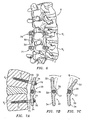
- the vertebral rod system is employed with a surgical procedure for treatment of a condition or injury of an affected section of the spine including vertebrae V, as shown in FIGS. 6 and 7 . It is contemplated that the vertebral rod system is attached to vertebrae V for dynamic stabilization of the affected section of the spine to provide stability for healing and therapeutic treatment, while allowing a desirable range of motion or load-sharing capability.
- a medical practitioner obtains access to a surgical site including vertebra V in any appropriate manner, such as through incision and retraction of tissues.
- the vertebral rod system may be used in any existing surgical method or technique including open surgery, mini-open surgery, minimally invasive surgery and percutaneous surgical implantation, whereby the vertebrae V is accessed through a mini-incision, or sleeve that provides a protected passageway to the area.
- the particular surgical procedure is performed for treating the spinal disorder.
- the vertebral rod system is then employed to augment the surgical treatment.
- the vertebral rod system can be delivered or implanted as a pre-assembled device or can be assembled in situ.
- the vertebral rod system may be completely or partially revised, removed or replaced, for example, replacing bumper 50 only, replacing rod 30 and bumper 50 and using the in-place fastening elements.
- a first fastening element such as, for example, fixation screw assembly 70 is configured to attach upper section 32 to vertebra V 1 .
- a second fastening element such as, for example, fixation screw assembly 71 is configured to attach lower section 34 to adjacent vertebra V 2 . Pilot holes are made in vertebrae V 1 , V 2 for receiving fixation screw assemblies 70, 71.
- Fixation screw assemblies 70, 71 include threaded bone engaging portions 72 that are inserted or otherwise connected to vertebrae V 1 , V 2 , according to the particular requirements of the surgical treatment.
- Fixation screw assemblies 70, 71 each have a head 74 with a bore, or through opening and a set screw 76, which is torqued on to sections 32, 34 to attach rod 30 in place with vertebrae V, as will be described.
- the vertebral rod system includes two axially aligned and spaced rods 30, with portions of sections 32, 34 extending through the bores of heads 74.
- Set screws 76 of each head 74 are torqued on the end portions of rods 30 to securely attach rods 30 with vertebrae V 1 , V 2 .
- vertebral rod 30 is configured to provide increasing resistance to movement of sections 32, 34 during flexion and extension of the spine.
- rod 30 reacts with increasing resistance during movement of rod 30 to a second, third or more orientation(s).
- the rod 30 can be attached to the spinal motion segment in the reverse orientation such that the bumper 50 and the opening in the intermediate section face away from the spinal motion segment.
- the bumper 50 is under less compression during flexion and more compression during extension of the spinal motion segment.
- the vertebral rod system can be used with various bone screws, pedicle screws or multi-axial screws (MAS) used in spinal surgery. It is contemplated that the vertebral rod system may be used with pedicle screws coated with an osteoconductive material such as hydroxyapatite and/or osteoinductive agent such as a bone morphogenic protein for enhanced bony fixation to facilitate motion of the treated spinal area.
- Rod 30 and bumper 50 can be made of radiolucent materials such as polymers. Radiomarkers may be included for identification under x-ray, fluoroscopy, CT or other imaging techniques.
- Metallic or ceramic radiomarkers such as tantalum beads, tantalum pins, titanium pins, titanium endcaps and platinum wires can be used, such as being disposed at the end portions of rod 30 and/or along the length thereof adjacent joint member 37 or with bumper 50.
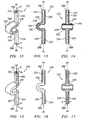
- a vertebral rod 130 in an alternate embodiment similar to vertebral rod 30 described above, includes an upper section 132 that defines a longitudinal axis aa and a lower section 134 that defines a longitudinal axis bb.
- Upper section 132 includes a first material, such as, for example, an elongated core 182 having a first modulus of elasticity.
- Lower section 134 includes a second material, such as, for example, an elongated core 184 having a second modulus of elasticity. It is contemplated that the materials having the first and second modulus may be in a range of 10 to 400 GPa and preferably in a range of 50 to 250 GPa. It is further contemplated that the first material and the second material may have alternate, different or substantially equal modulus of elasticity.
- Vertebral rod 130 is a composite dynamic or load-sharing device and sections 132, 134 each have a reinforced configuration based on the configuration of cores 182, 184 such that rod 130 has increased segmental rigidity and strength while achieving overall rod flexibility and durability during use.
- An outer layer 186 is disposed about core 182 and is formed of a material, such as those described herein, having a modulus of elasticity that is less than the first modulus of elasticity to provide flexibility and compliance to upper section 132.
- Outer layer 186 has a low modulus of elasticity relative to core 182 and surrounds core 182, which is formed of a material having a high modulus of elasticity to provide increased segmental stiffness and strength to vertebral rod 130 during a force/stress application, as will be described below.
- An outer layer 188 is disposed about core 184 and is formed of a material having a modulus of elasticity that is less than the second modulus of elasticity to provide flexibility and compliance to lower section 134.
- Outer layer 188 has a low modulus of elasticity relative to core 184 and surrounds core 184, which is formed of a material having a high modulus of elasticity to provide increased stiffness and strength to vertebral rod 130 during a force/stress application.
- Cores 182, 184 can include a high modulus of elasticity material such as, for example, grade 5 titanium (Ti-6A1-4V), Commercially Pure Titanium (CP Ti), cobalt-chromium (Co-Cr), stainless steel, Nitinol, and/or carbon-reinforced polyetheretherketone PEEK, commercially pure titanium, titanium alloys, super-elastic titanium alloys, cobalt-chrome alloys, stainless steel alloys and/or PEEK reinforced with long and/or continuous carbon fibers.
- Outer layers 186, 188 can include a low modulus material such as PEEK, PEEK reinforced with short and/or chopped carbon fibers, polyurethane, epoxy, CPT, and/or Nitinol.
- Outer layers 186, 188 may include a sleeve, coating or wrap disposed about cores 182, 184.
- Cores 182, 184 may extend along the entire rod section, or only a portion thereof. It is contemplated that cores 182, 184 may extend into an intermediate section 136 of vertebral rod 130, discussed below, and to an inner surface 138 of intermediate section 136.
- Sections 132, 134, 136 may include a material change along their respective length.
- materials used for higher modulus regions include cobalt-chrome alloys, titanium alloys, superelastic metallic alloys (e.g. Nitinol, super elasto-plastic metals, such as GUM METAL® manufactured by Toyotsu Material Incorporated of Japan), stainless steel alloys, continuous carbon fiber reinforced PEEK and/or short carbon fiber reinforced PEEK.
- materials used for lower modulus regions include PEEK, short carbon fiber reinforced PEEK, continuous-carbon fiber reinforced PEEK, superelastic metallic alloys (e.g. Nitinol, super elasto-plastic metals, such as GUM METAL® manufactured by Toyotsu Material Incorporated of Japan), PEKK, polyurethane, polyethylene and/or polyphenylene.
- each of cores 182, 184 may have alternate shapes such as round, oval, elliptical, oblong, square, rectangular, triangular, pentagonal and hexagonal. It is envisioned that each of cores 182, 184 may have a variable cross section along its length.
- the cores 182, 184 and/or outer layers 186, 188 may have machined surfaces, polished surfaces, smooth surfaces, textured surfaces, shot-peened surfaces, burnished surfaces, porous surfaces, patterned surfaces and wavy surfaces.
- the surfaces of cores 182, 184 and/or outer layers 186, 188 may be chemically treated or modified using various processes or materials which include oxidation, anodization, plasma treatment, vapor deposition, plating, coating and etching. It is contemplated that the vertebral rod may employ a heterogeneous composite, having a non-uniform carbon content.
- Cores 182, 184 and/or outer layers 186, 188 may be located centrally or at an offset distance from axes aa, bb of rod 130. It is contemplated that rod 130 may have a continuous or non-continuous core. Outer layers 186, 188 can be continuous, non-continuous, and/or provide complete or incomplete coverage of cores 182, 184. It is envisioned that outer layers 186, 188 can be solid or porous, for example, a solid sheath, a perforated sheath and a woven sheath. It is further envisioned that outer layers 186, 188 include a single material or a composite material, or may be of variable thickness around a core, and/or include a variable thickness along a core.
- longitudinal axis aa may be disposed at various angular orientations relative to longitudinal axis bb, such as, for example, those discussed herein.
- sections 132, 134 may include a laterally offset orientation, arcuate portion(s) and alternate lengths, such as, for example, those discussed herein. Movement of vertebral rod 130 between one or a plurality of orientations is envisioned and may include a range of increasing and decreasing levels of resistance. It is envisioned that sections 132, 134 can be bent, curved or deformed using a bending technique with or without heating. It is further envisioned that the respective core facilitates the desirable bending or deformed shape.
- An intermediate section 136 is connected with sections 132, 134 and disposed therebetween as a joining section of the components of vertebral rod 130, similar to the intermediate sections discussed herein.
- Intermediate section 136 is formed of a third material having a third modulus of elasticity.
- the first modulus and the second modulus are each greater than the third modulus such that upper section 132 and lower section 134 provide a reinforced configuration of vertebral rod 130 and intermediate section 136 has a relatively flexible configuration. It is further contemplated that the first, second and third materials may have alternate, different or substantially equal modulus of elasticity.
- intermediate section 136 may have a different shape, geometry or cross-section configuration relative to sections 132, 134.
- Intermediate section 136 may have an arcuate section, curvature or bend.
- Intermediate section 136 may have a C or U shaped to increase flexibility and fatigue resistance.
- Intermediate section 136 may have a substantially rectangular cross-section configuration to increase flexibility and fatigue resistance.
- Intermediate section 136 has a low modulus of elasticity for flexibility relative to cores 182, 184, which are formed of a material having a high modulus of elasticity to provide increased segmental stiffness and strength to vertebral rod 130 during a force/stress application.
- Intermediate section 136 can include a low modulus material such as PEEK, short or chopped carbon fiber PEEK, PEEK with a low percentage of short and/or chopped carbon fibers such as in a range of 1 to 10% PEEK only with no reinforcement and/or partially reinforced such that a non-continuous reinforcement is provided across the flexible portion of the intermediate section with a gradually decreasing reinforcement toward the middle of the intermediate section. It is contemplated that intermediate section 136 is fully reinforced such that a continuous reinforcement is disposed across the flexible portion of the intermediate section.
- Intermediate section 136 includes a flexible joint member 137, which has a U-shaped configuration and defines corresponding shaped arcuate inner surface 138 and an open end 140.
- Open end 140 defines a spaced apart dimension of the gap or opening defined thereby, and defines the spaced apart region of intermediate section 136 disposed between sections 132, 134. It is envisioned that height of open end 140 may be in a range of 3-20 mm, preferably in a range of 3-15 mm, and most preferably in a range of 3-10 mm.
- Sections 132, 134 each define a dimension of thickness.
- section 132 defines an outside diameter that includes twice the thickness of outer layer 186 and the diameter of core 182.
- Section 134 defines an outside diameter that includes twice thickness of outer layer 188 and the diameter of core 184.
- the outside diameter of sections 132, 134 may be in a range of 2-11 mm, preferably in a range of 2.5-9 mm, and most preferably in a range of 3-7 mm.
- sections 132, 134 may have alternate geometric cross-section configurations, for example, elliptical, rectangular, polygonal, irregular, uniform and non-uniform.
- Flexible joint member 137 is enlarged relative to sections 132, 134, as shown in FIG. 10 , and defines a width w. It is envisioned that width w of flexible joint member 137 may be in a range of 3-20 mm, preferably in a range of 3-15 mm, and most preferably in a range of 3-10 mm. Flexible joint member 137 further defines a thickness and it is envisioned that thickness of flexible joint member 137 may be in a range of 1-10 mm, preferably in a range of 2-8 mm, and most preferably in a range of 2-6 mm. It is contemplated that flexible joint member 137 may have alternate geometric cross-section configurations, for example, round, oval, rectangular, polygonal, irregular, uniform and non-uniform.
- Vertebral rod 130 may be employed with a surgical procedure for treating a spinal disorder, similar to that discussed above.
- the vertebral rod system may be employed with pedicle-based dynamic spinal rods or devices, flexible composite rods, posterior transition devices, posterior load-sharing devices or spinal rods, and low-modulus spinal rods. It is contemplated that the vertebral rod system may be employed with minimally invasive applications, such as, for example, those employing rod section diameters approximating 4.75 mm and/or 5.5 mm.
- a graphical diagram of force (N) vs. displacement (mm) illustrates calculated deflection of vertebral rod 130 under stress for alternate embodiments of cores 182, 184.
- cores 182, 184 can include alternate materials and thickness in accordance with the principles of the present disclosure.
- the data provided in Fig. 11 was obtained via computational modeling of PTD spinal rod stiffness cantilever beam loading for PEEK composite rods having a length of 100 mm and an outer diameter of 4.75 mm with various core materials and dimensions except when noted.
- sections 132, 134 have 4.75 mm cross section of a solid PEEK material having no metal core, which has a total deformation of approximately 13 mm over a stress application equivalent to 5 N.
- sections 132, 134 have 3 mm cores 182, 184 of Ti material, which has a total deformation of 5.1092 mm over a stress application equivalent to 5 N.
- sections 132, 134 have 3 mm cores 182, 184 of Co Cr material, which has a total deformation of 4.1128 mm over a stress application equivalent to 5 N.
- sections 132, 134 have 2 mm cores 182, 184 of Ti material, which has a total deformation of 9.3756 mm over a stress application equivalent to 5 N.
- sections 132, 134 have 2 mm cores 182, 184 of Co Cr material, which has a total deformation of 7.9513 mm over a stress application equivalent to 5 N.
- sections 132, 134 have 4 mm cores 182, 184 of Ti material, which has a total deformation of 3.8496 mm over a stress application equivalent to 5 N.
- sections 132, 134 have 4 mm cores 182, 184 of Co Cr material, which has a total deformation of 3.4382 mm over a stress application equivalent to 5 N.
- sections 132, 134 have oval cross section (6.35 mm by 7.2 mm) of solid PEEK material no metal core, which has a total deformation of 3.7873 mm over a stress application equivalent to 5 N.
- sections 132, 134 have 3.5 mm cores 182, 184 of Co Cr material, which has a total deformation of 3.4118 mm over a stress application equivalent to 5 N.
- sections 132, 134 have 3.5 mm cores 182, 184 of Ti material, which has a total deformation of 4.0521 mm over a stress application equivalent to 5 N.
- sections 132, 134 may be made of composite materials such as a Co-Cr core disposed within a PEEK sleeve or outer layer or coating with a flexible intermediate section 136 of a lower modulus material such as PEEK, with a material change along the rod length and rod cross section.
- sections 132, 134 are made of high modulus materials such as Co-Cr or Ti-6A1-4V or long and/or continuous carbon fiber PEEK
- the flexible intermediate section 136 is made of a composite material such as a Co-Cr core or Ti-6A1-4V core in a PEEK sleeve with a material change along the rod length, and along the rod cross-section.
- sections 132, 134 are made of composite materials such as 30% short and/or chopped carbon fiber in PEEK
- flexible intermediate section 136 is made of a composite material such as 10% short carbon fiber in PEEK, with a change of carbon fiber content along the rod length.
- a vertebral rod 230 in an alternate embodiment similar to vertebral rod 130 described above, includes an upper section 232 and a lower section 234.
- Upper section 232 includes an elongated core 282 having the first modulus of elasticity
- lower section 234 includes an elongated core 284 having a second modulus of elasticity, as described above.
- Sections 232, 234 each have a reinforced configuration based on the configuration of cores 282, 284 such that vertebral rod 230 has increased rigidity and strength during use.
- An outer layer 286 is disposed about core 282 and is formed of a material having a modulus of elasticity that is less than the first modulus of elasticity to provide flexibility and compliance to upper section 232.
- Outer layer 286 has a low modulus of elasticity relative to core 282 and surrounds core 282, which is formed of a material having a high modulus of elasticity to provide increased stiffness and strength to vertebral rod 230.
- An outer layer 288 is disposed about core 284 and is formed of a material having a modulus of elasticity that is less than the second modulus of elasticity to provide flexibility and compliance to lower section 234.
- Outer layer 288 has a low modulus of elasticity relative to core 284 and surrounds core 284, which is formed of a material having a high modulus of elasticity to provide increased stiffness and strength to vertebral rod 230.
- An intermediate section 236 is connected with sections 232, 234 and disposed therebetween as a joining section of the components of vertebral rod 230.
- Intermediate section 236 includes a reinforcement portion, such as, for example, a core 290 formed of a material having a modulus of elasticity that is greater than the third modulus, discussed above.
- Core 290 has an arcuate configuration that conforms to the configuration of arcuate inner surface 238.
- Intermediate section 236 has an outer layer 292 formed of the third material having the third modulus of elasticity.
- Outer layer 292 has a low modulus of elasticity relative to core 290 and surrounds core 290, which is formed of a material having a high modulus of elasticity to provide increased stiffness and strength to vertebral rod 230 during a force/stress application. Outer layer 292 has a modulus of elasticity that is less than the modulus of elasticity of core 290 to provide flexibility and compliance to intermediate section 236.
- the cross section configuration of core 290 may have alternate shapes such as round, oval, elliptical, oblong, square, rectangular, triangular, pentagonal and hexagonal.
- Core 290 may have a variable cross section along its length.
- Core 290 may have machined surface, polished surface, smooth surface, textured surface, shot-peened surface, burnished surface, porous surface, patterned surface and wavy surface.
- the surface of core 290 may be chemically treated or modified using various processes or materials which include oxidation, anodization, plasma treatment, vapor deposition, plating, coating and etching.
- Core 290 can be continuous or non-continuous.
- Outer layer 292 can be continuous, non-continuous and/or provide complete or incomplete coverage of core 290.
- Outer layer 292 can be solid or porous such as a solid sheath, a perforated sheath, a woven sheath and/or a sleeve configuration. It is contemplated that outer layer 292 may include a single material or a composite material, be of variable thickness around core 290, and/or be of variable thickness along core 290.
- the modulus of elasticity of cores 282, 284 and 290 are equal and greater than the third modulus such that upper section 232, lower section 234 and intermediate section 236 provide a reinforced configuration of vertebral rod 230 with their respective outer layers providing flexibility and compliance. It is contemplated that the modulus of core 290 may be in a range of 10 to 400 GPa and preferably in a range of 50 to 250 GPa. It is further contemplated that the modulus of elasticity of cores 282, 284 and 290 may be alternate or substantially equal modulus of elasticity.
- Core 290 connects cores 282 and 284 such that sections 232, 234 and 236 are in a continuous reinforcement configuration of vertebral rod 230. It is envisioned that cores 282, 284 and 290 may include partial reinforcement including a non-continuous high modulus material, such as intermittent or multiple sections and alternatively, may include complete reinforcement including continuous high modulus material.
- a vertebral rod 330 in an alternate embodiment similar to vertebral rod 30 described above, includes an upper section 332 and a lower section 334.
- Upper section 332 includes a first material, such as, for example, an outer layer 386 having a first modulus of elasticity.
- Lower section 334 includes a second material, such as, for example, an outer layer 388 having a second modulus of elasticity.
- the first and second modulus may be in a range of 10 to 400 GPa and preferably in a range of 50 to 250 GPa. It is further contemplated that the first material and the second material may be of alternate or substantially equal modulus of elasticity.
- Vertebral rod 330 is a composite dynamic device and sections 332, 334 each have a reinforced configuration based on the configuration of outer layers 386, 388 such that vertebral rod 330 has increased rigidity and strength during use.
- Outer layer 386 is disposed about an elongated core 382, which is formed of a material, such as those described herein, having a modulus of elasticity that is less than the first modulus of elasticity to provide flexibility and compliance to upper section 332.
- Core 382 has a low modulus of elasticity relative to outer layer 386 and is disposed within outer layer 386, which is formed of a material having a high modulus of elasticity to provide increased stiffness and strength to vertebral rod 330 during a force/stress application.
- Outer layer 388 is disposed about an elongated core 384 and is formed of a material having a modulus of elasticity that is less than the second modulus of elasticity to provide flexibility and compliance to lower section 334.
- Core 384 has a low modulus of elasticity relative to outer layer 388 and is disposed within outer layer 388, which is formed of a material having a high modulus of elasticity to provide increased stiffness and strength to vertebral rod 330 during a force/stress application.
- Outer layers 386, 388 can include a high modulus of elasticity material such as, for example, commercially pure titanium, titanium alloys, super-elastic titanium alloys, cobalt-chrome alloys, stainless steel alloys and/or PEEK reinforced with long and/or continuous carbon fibers.
- Cores 382, 384 can include a low modulus material such as PEEK and/or PEEK reinforced with short and/or chopped carbon fibers.
- Outer layers 386, 388 may include a sleeve, coating or wrap disposed about cores 382, 384.
- outer layers 386, 388 may have alternate shapes such as round, oval, elliptical, oblong, square, rectangular, triangular, pentagonal and hexagonal.
- Outer layers 386, 388 may have variable cross sections along the length of rod 330.
- Outer layers 386, 388 may have machined surfaces, polished surfaces, smooth surfaces, textured surfaces, shot-peened surfaces, burnished surfaces, porous surfaces, patterned surfaces and wavy surfaces.
- the surface of outer layers 386, 388 may be chemically treated or modified using various processes or materials which include oxidation, anodization, plasma treatment, vapor deposition, plating, coating and etching.
- Outer layers 386, 388 can be continuous or non-continuous.
- Outer layers 386, 388 may provide continuous, non-continuous, complete or incomplete coverage of the cores.
- Outer layers 386, 388 may be solid or porous, for example, a solid sheath, a perforated sheath and a woven sheath. It is envisioned that outer layers 386, 388 may be a single material or a composite material, of variable thickness around the core and/or of variable thickness along the core.
- An intermediate section 336 similar to intermediate section 136 described above, is connected with sections 332, 334 and disposed therebetween as a joining section of the components of vertebral rod 330, whereby upper section 332 and lower section 334 provide a reinforced configuration of rod 330 and intermediate section 336 has a relatively flexible configuration.
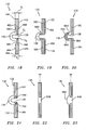
- an alternate embodiment of vertebral rod 130 includes a first section 432 having a first elongated core 482 formed of a material having the first modulus of elasticity, described above and having a cross section extending from a first end 494 of first section 432 to inner surface 138 of intermediate section 136.
- the cross section of core 482 comprises an outer diameter D 1 of first section 432 adjacent first end 494, a tapered portion 496 and extending to a reduced diameter D 2 , relative to outer diameter D o , adjacent to inner surface 138.
- An outer layer 486 having a modulus of elasticity less than the first modulus of elasticity is disposed about tapered portion 496. As the thickness of core 482 decreases to inner surface 138, the thickness of outer layer 486 increases.
- Vertebral rod 130 includes a second section 434 having a second elongated core 484 formed of a material having the second modulus of elasticity, described above, and having a cross section extending from a first end 496 of second section 434 to inner surface 138.
- the cross section of core 484 comprises an outer diameter D 3 of second section 434 adjacent first end 496, a tapered portion 498 with a reduced diameter D 4 , relative to outer diameter D 3 , adjacent to inner surface 138.
- An outer layer 488 having a modulus of elasticity less than the second modulus of elasticity, is disposed about tapered portion 496. As the thickness of core 484 decreases to inner surface 138, the thickness of outer layer 488 increases. This configuration provides increased flexibility and compliance adjacent intermediate section 136.
- vertebral rod 130 includes section 132 having a core reinforcement 582 formed of a material having the first modulus of elasticity, described above and extending to at least partially within intermediate section 136.
- Vertebral rod 130 also includes section 134 having a core reinforcement 584 formed of a material having the second modulus of elasticity, described above and extending to at least partially within intermediate section 136.
- An outer layer 488 of section 134 and outer layer 590, each having a modulus of elasticity less than the second modulus of elasticity, are disposed about core reinforcement 584. This configuration of vertebral rod 130 provides partial reinforcement into intermediate section 138.
- vertebral rod 130 includes a reinforcement core 690, having a relatively high modulus of elasticity, is disposed within intermediate section 136.
- Reinforcement core 690 has an arcuate configuration and conforms to the shape of inner surface 138.
- An outer layer 692 having a low modulus of elasticity relative to core 690, is disposed about reinforcement core 690.
- Core 690 has a first end 693 spaced apart from core 182 and a second end 694 spaced apart from core 184 to provide partial reinforcement into intermediate section 138.
- vertebral rod 130 includes cores 182, 184 having dovetail reinforcement connections 790, 792, having the first and second modulus of elasticity, respectively.
- Dovetail reinforcement connections 790, 792 are disposed adjacent opening 140 and connect sections 132, 134 to intermediate section 136, while providing increased strength and rigidity to vertebral rod 130.
- another alternate embodiment of vertebral rod 130 includes an intermediate section 836 having a linear configuration in axial alignment with axis aa, in the non stressed orientation.
- Intermediate section 836 is formed of a material having the third modulus of elasticity, as described above.
- another alternate embodiment of vertebral rod 130 includes an intermediate section 936 having a linear configuration in axial alignment with axis aa, in the non stressed orientation.
- Intermediate section 936 is formed of a material having the third modulus of elasticity and includes a lateral protuberance 990 to enhance strength and rigidity.
- another alternate embodiment of vertebral rod 130 includes an intermediate section 936A, which has a reduced curvature profile.
- 936A has an arcuate configuration such that a lateral protuberance 990A of intermediate section 936A enhances strength and rigidity of vertebral rod 130.
- an alternate embodiment of vertebral rod 330 described above with regard to FIGS. 15-17 includes an intermediate section 1036 having a linear configuration in axial alignment with axis aa, in the non stressed orientation.
- Intermediate section 1036 is formed of a material having the third modulus of elasticity, as described above.
- another alternate embodiment of vertebral rod 130 includes an intermediate section 1136 having a linear configuration in axial alignment with axis aa, in the non stressed orientation.
- Cores 182, 184 extend in a uniform cross section to diverging leg portions extending to Intermediate section 1136.
- Intermediate section 1136 is formed of a material having the third modulus of elasticity, as described above.
- vertebral rod 130 includes an intermediate section 1236 having a linear configuration in axial alignment with axis aa, in the non stressed orientation.
- Intermediate section 1236 is formed of a material having the third modulus of elasticity and includes a pair of opposing lateral protuberances 1290 to enhance strength and rigidity.
- a vertebral rod 1330 in an alternate embodiment similar to vertebral rod 130 described above, includes an upper section 1332 and a lower section 1334.
- Upper section 1332 includes a first material 1390, which is a polymer composite such as carbon-PEEK or carbon-PEKK having a first modulus of elasticity.
- Lower section 1334 includes a second material 1392, which is a polymer composite such as carbon-PEEK or carbon-PEKK having a second modulus of elasticity.
- the first and second modulus may be in a range of 2.5 to 100 GPa and preferably in a range of 5 to 50 GPa. It is further contemplated that the first material and the second material may have alternate or substantially equal modulus of elasticity.
- Vertebral rod 1330 is a non uniform composite dynamic device and has a reinforced configuration based on the configuration of the first and second materials such that vertebral rod 1330 has increased rigidity and strength during use.
- Sections 1332, 1334 are highly reinforced with for example carbon fibers for improved stiffness and strength.
- An intermediate section 1336 similar to intermediate section 136 discussed above, is not reinforced or lightly reinforced for flexibility and compliance.
- Transitions zones 1337 are disposed between sections 1332, 1334 and intermediate section 1336. It is preferred that transition zones 1337 have gradual changes in reinforcement (e.g. percentage of carbon fiber) to induce gradual changes in modulus between sections 1332, 1334 and intermediate section 1336. Gradual changes in modulus are expected to minimize stress risers and potential for failures at transition zones 1337. It is contemplated that transition zones 1337 and/or intermediate section 1336 may include a uniform reinforcement with no gradual change.
- alternate embodiments of vertebral rod 130 described above illustrate examples of multiple level composite rods with multiple flexible intermediate sections. It is envisioned that each of the intermediate sections may be alternately configured. For example, a first intermediate section may be more flexible than a second or third intermediate section due to differences in geometry, cross-sectional area or material composition. It is further envisioned that an intermediate section with higher flexibility may be used to support an unfused or motion-preserving level of a spine. As such, an intermediate section with higher stiffness may be used to support the fused level, where an optimal balance between stabilization and load-sharing is desirable.
- the reinforcement material or core of the vertebral rod may be different for the screw engaging sections of the rod to provide a different stiffening effect to different sections of the rod.
- an upper section of the rod may be reinforced with a 3.5mm Co-Cr core
- a flexible intermediate section may be reinforced with a 3.0 mm short and/or chopped carbon fiber reinforced PEEK
- a lower section may be reinforced with 2.5 mm Ti-6A1-4V.
- a vertebral rod 1430 includes an upper section 1432 and a mid section 1434.
- Upper section 1432 includes an elongated core 1482 having a first modulus of elasticity.
- Mid section 1434 includes an elongated core 1484 having a second modulus of elasticity.
- the first and second modulus may be in a range of 0 to 400 GPa and preferably in a range of 50 to 250 GPa. It is further contemplated that the first material and the second material may have alternate or substantially equal modulus of elasticity.
- An outer layer 1486 is disposed about core 1482 and is formed of a material, such as those described herein, having a modulus of elasticity that is less than the first modulus of elasticity to provide flexibility and compliance to upper section 1432.
- An outer layer 1488 is disposed about core 1484 and is formed of a material having a modulus of elasticity that is less than the second modulus of elasticity to provide flexibility and compliance to lower section 1434.
- a first flexible intermediate section 1436 similar to intermediate section 136 described above, is connected with sections 1432, 1434 and disposed therebetween as a joining section of the components of vertebral rod 1430.
- Intermediate section 1436 is formed of a third material having a third modulus of elasticity. The first modulus and the second modulus are each greater than the third modulus such that upper section 1432 and mid section 1434 provide a reinforced configuration of rod 1430 and intermediate section 1436 has a relatively flexible configuration.
- a third elongated section such as, for example, a lower section 1490 includes a fourth material, such as, for example an elongated core 1492 having a fourth modulus of elasticity.
- the fourth modulus is greater than the third modulus such that lower section 1490 provides a reinforced configuration of rod 1430.
- An outer layer 1494 is disposed about core 1492 and is formed of a material, such as those described herein, having a modulus of elasticity that is less than the fourth modulus of elasticity to provide flexibility and compliance to lower section 1490. It is contemplated that the fourth modulus may be in a range of 10 to 400 GPa and preferably in a range of 50 to 250 GPa. It is further contemplated that the fourth material, the first material and the second material may have alternate or substantially equal modulus of elasticity.
- a second flexible intermediate section 1496 is connected with sections 1434, 1490 and disposed therebetween as a joining section.
- Intermediate section 1496 has a linear configuration in axial alignment with sections 1434, 1490, in the non stressed orientation.
- Intermediate section 1496 is formed of a material having a modulus of elasticity lower than the fourth modulus.
- Section 1490 has a modulus greater than the modulus of intermediate section 1496 such that lower section 1490 provides a reinforced configuration of rod 1430 and intermediate section 1496 has a relatively flexible configuration.
- Intermediate section 1496 may be more or less flexible than intermediate section 1436 depending on the geometry, cross sectional area and material composition of the components of vertebral rod 1430.
- Vertebral rod 1430 has an increased length providing the ability to extend over two or more intervertebral disc levels. It is contemplated that the configuration of the vertebral rod system may provide dynamic or flexible stabilization over a plurality of intervertebral levels, including treated and untreated vertebral and intervertebral levels. It is further contemplated that intermediate section 1496 and lower section 1490 provides a less flexible, or more rigid stabilization relative to other components of vertebral rod 1430. Vertebral rod 1430 may be cut or trimmed during a surgical procedure such that the size of vertebral rod 1430 can be modified according to patient needs or the particular requirements of a surgical treatment or medical practitioner. Vertebral rod 1430 may be provided in precurved configurations with various levels of curvature to fit anatomical variations. Alternatively, a straight or pre-curved vertebral rod 1430 can be bent or reshaped intraoperatively to fit specific patient anatomy.
- vertebral rod 1430 discussed above includes a first orientation whereby longitudinal axis aa is disposed at an angle of 180 degrees relative to longitudinal axis bb. It is contemplated that longitudinal axis aa may be disposed at other angular orientations relative to longitudinal axis bb .
- Sections 1434, 1496, 1490 have an arcuate configuration and increased length providing the ability to extend over two or more intervertebral elements.
- Lower section 1490 may be cut or trimmed during a surgical procedure such that the size of vertebral rod 1430 can be modified according to patient needs or the particular requirements of a surgical treatment or medical practitioner.
- the arcuate configuration of sections 1434, 1496, 1490 has a radius of curvature rr. Desirably, the radius of curvature rr is in a range of 20-400 mm, preferably in a range of 50-200 mm, and most preferably in a range of 100-150 mm.
- vertebral rod 1430 discussed above includes a second flexible intermediate section 1596, which has a reduced curvature profile.
- An inner surface 1538 of intermediate section 1536 has an arcuate configuration such that a lateral protuberance 1590 of intermediate section 1596 enhances strength and rigidity of vertebral rod 1430.
- Intermediate section 1596 may be used for load sharing stabilization at the fusion level of a spine.
- vertebral rod 1430 includes a second flexible section 1696 having a pair of opposing lateral protuberances 1698 to enhance strength, and rigidity of vertebral rod 1430.
- vertebral rod 1430 includes a second flexible section 1796 having a lateral protuberance 1798 to enhance strength and rigidity of vertebral rod 1430.
- vertebral rod 1430 has a first flexible intermediate section having a C or U shaped configuration, with a second flexible intermediate section having an equivalent profile.
- Both flexible intermediate sections are made of PEEK only.
- the upper and lower sections have a core made of higher modulus material such as Co-Cr or Ti-6Al-4V or long and/or continuous carbon fiber PEEK, and an outer sleeve disposed thereabout made of a lower modulus material PEEK.
- the first flexible intermediate section may be relatively more flexible than the second flexible intermediate section due to its C or U shaped configuration. It is contemplated that the two separate flexible intermediate sections have the same material composition with different geometries.
Landscapes
- Health & Medical Sciences (AREA)
- Orthopedic Medicine & Surgery (AREA)
- Life Sciences & Earth Sciences (AREA)
- Neurology (AREA)
- Surgery (AREA)
- Heart & Thoracic Surgery (AREA)
- Engineering & Computer Science (AREA)
- Biomedical Technology (AREA)
- Nuclear Medicine, Radiotherapy & Molecular Imaging (AREA)
- Medical Informatics (AREA)
- Molecular Biology (AREA)
- Animal Behavior & Ethology (AREA)
- General Health & Medical Sciences (AREA)
- Public Health (AREA)
- Veterinary Medicine (AREA)
- Prostheses (AREA)
- Surgical Instruments (AREA)
Claims (12)
- Une tige vertébrale (130, 230, 1430), comportant :une section supérieure (132, 232, 1432) définissant un axe longitudinal (aa) et incluant un premier matériau (182, 282, 1482) ayant un premier module d'élasticité et une couche externe (186, 286, 1486) disposée autour du premier matériau (182, 282, 1482),une section inférieure (134, 234, 1434) définissant un axe longitudinal (bb) et incluant un deuxième matériau (184, 284, 1484) ayant un deuxième module d'élasticité et une couche externe (188, 288, 1488) disposée autour du deuxième matériau (184, 284, 1484), etune première section intermédiaire (136, 236, 1436) disposée entre la section supérieure (132, 232, 1432) et la section inférieure (134, 234, 1434), et étant formée d'un troisième matériau ayant un troisième module d'élasticité, la section intermédiaire (136, 236, 1436) ayant une surface intérieure arquée (138, 238) qui définit une cavité (146) et une extrémité ouverte (140),caractérisée en ce quedans laquelle le premier module et le deuxième module sont chacun supérieur au troisième module, de sorte que les sections supérieure et inférieure (132, 134 ; 232, 234 ; 1432, 1434) fournissent une configuration renforcée de la tige vertébrale (130, 230, 1430) et la section intermédiaire (136, 236, 1436) a une configuration relativement flexible,la couche externe (186, 286, 1486) de la section supérieure est formée d'un matériau ayant un module d'élasticité qui est inférieur au premier module, etla couche externe (188, 288, 1488) de la section inférieure est formée d'un matériau ayant un module d'élasticité qui est inférieur au deuxième module.
- Une tige vertébrale (130, 1430) selon la revendication 1, dans laquelle le premier module d'élasticité est essentiellement égal au deuxième module d'élasticité, ou dans laquelle le premier module d'élasticité est différent du deuxième module d'élasticité.
- Une tige vertébrale (130, 230) selon la revendication 1, dans laquelle au moins une partie de la section intermédiaire (136, 236) inclut une partie de renforcement (690, 290) ayant un module d'élasticité qui est supérieur au troisième module, le troisième matériau étant une couche externe (692, 292) disposée autour de la partie de renforcement (690, 290).
- Une tige vertébrale (130, 230) selon la revendication 3, dans laquelle la partie de renforcement (690, 290) de la section intermédiaire (136, 236) a une configuration arquée.
- Une tige vertébrale (230) selon la revendication 4, dans laquelle la partie de renforcement (290) relie le premier matériau (282) avec le deuxième matériau (284), de sorte que les sections supérieure, inférieure et intermédiaire (232, 234, 236) sont dans une configuration de renforcement continue de la tige vertébrale (230).
- Une tige vertébrale (130) selon la revendication 1, dans laquelle le premier matériau est un noyau allongé (482) ayant une coupe transversale s'étendant à partir d'une première extrémité (494) de la section supérieure (432) à la surface intérieure (138) de la section intermédiaire (136), la coupe transversale du noyau comportant un diamètre extérieur de la section supérieure (432) adjacent à la première extrémité (494) et incluant une partie effilée (496) à diamètre réduit relativement au diamètre extérieur, adjacent à la surface intérieure (138).
- Une tige vertébrale (130) selon la revendication 6, dans laquelle le deuxième matériau est un noyau allongé (484) ayant une coupe transversale s'étendant à partir d'une première extrémité (496) de la section inférieure (434) à la surface intérieure (138) de la section intermédiaire (136), la coupe transversale du noyau de la section inférieure (434) comportant un diamètre extérieur de la section inférieure (434) adjacent à la première extrémité (496) de la section inférieure (434) et incluant une partie effilée (498) à diamètre réduit relativement au diamètre extérieur de la section inférieure (434), adjacent à la surface intérieure (138).
- Une tige vertébrale (130) selon la revendication 4, dans laquelle la partie de renforcement (690) de la section intermédiaire (136) est disposée de manière arquée autour de la surface intérieure (138) et ayant une première extrémité (693), la première extrémité (693) étant espacée du premier matériau (182).
- Une tige vertébrale (130) selon la revendication 8, dans laquelle la partie de renforcement (690) de la section intermédiaire (136) a une deuxième extrémité (694) qui est espacée du deuxième matériau (184).
- Une tige vertébrale selon la revendication 1, dans laquelle le premier matériau et le deuxième matériau sont chacun un composite polymère ayant une concentration de fibre de carbone.
- Une tige vertébrale (1430) selon la revendication 1, comportant en outre une troisième section allongée (1490) incluant un quatrième matériau (1492) ayant un quatrième module d'élasticité, et une deuxième section intermédiaire flexible (1496) disposée entre la section inférieure (1434) et la troisième section (1490), dans laquelle le quatrième module est supérieur au troisième module.
- Une tige vertébrale (1430) selon la revendication 11, dans laquelle la deuxième section intermédiaire (1796) inclut une protubérance latérale (1798).
Applications Claiming Priority (2)
| Application Number | Priority Date | Filing Date | Title |
|---|---|---|---|
| US12/566,133 US9011494B2 (en) | 2009-09-24 | 2009-09-24 | Composite vertebral rod system and methods of use |
| PCT/US2010/050035 WO2011038141A1 (fr) | 2009-09-24 | 2010-09-23 | Système de tige vertébrale composite et procédés d'utilisation |
Publications (2)
| Publication Number | Publication Date |
|---|---|
| EP2480148A1 EP2480148A1 (fr) | 2012-08-01 |
| EP2480148B1 true EP2480148B1 (fr) | 2015-03-04 |
Family
ID=43127363
Family Applications (1)
| Application Number | Title | Priority Date | Filing Date |
|---|---|---|---|
| EP10768832.7A Not-in-force EP2480148B1 (fr) | 2009-09-24 | 2010-09-23 | Système de tige vertébrale composite |
Country Status (5)
| Country | Link |
|---|---|
| US (1) | US9011494B2 (fr) |
| EP (1) | EP2480148B1 (fr) |
| CN (1) | CN102510741A (fr) |
| AU (1) | AU2010298241B2 (fr) |
| WO (1) | WO2011038141A1 (fr) |
Families Citing this family (15)
| Publication number | Priority date | Publication date | Assignee | Title |
|---|---|---|---|---|
| DE102010000339A1 (de) * | 2010-02-08 | 2011-08-11 | Aesculap AG, 78532 | Verbindungselement für ein Wirbelsäulenstabilisierungssystem und Wirbelsäulenstabilisierungssystem |
| US20120316430A1 (en) * | 2011-06-10 | 2012-12-13 | Cibor, Inc. | Radiolucent surgical instruments |
| WO2013016523A1 (fr) * | 2011-07-28 | 2013-01-31 | Synthes Usa, Llc | Implants orthopédiques |
| US20130110169A1 (en) * | 2011-10-26 | 2013-05-02 | Warsaw Orthopedic, Inc. | Vertebral rod system and methods of use |
| WO2013170262A2 (fr) * | 2012-05-11 | 2013-11-14 | Orthopediatrics Corp. | Connecteurs chirurgicaux et instrumentation |
| US10786283B2 (en) * | 2013-08-01 | 2020-09-29 | Musc Foundation For Research Development | Skeletal bone fixation mechanism |
| US10588642B2 (en) * | 2014-05-15 | 2020-03-17 | Gauthier Biomedical, Inc. | Molding process and products formed thereby |
| EP3015084B1 (fr) * | 2014-10-30 | 2017-05-10 | K2M, Inc. | Élément de fixation vertébrale |
| ES2932049T3 (es) | 2015-11-13 | 2023-01-09 | Oppilan Pharma Ltd | Compuestos heterocíclicos para el tratamiento de enfermedades |
| US11583318B2 (en) | 2018-12-21 | 2023-02-21 | Paradigm Spine, Llc | Modular spine stabilization system and associated instruments |
| JP7446965B2 (ja) * | 2020-09-29 | 2024-03-11 | グローブライド株式会社 | 脊椎固定具用ロッド |
| US20230225765A1 (en) * | 2022-01-18 | 2023-07-20 | Medos International Sarl | Spinal fixation rod having a core and an outer layer |
| US12612401B2 (en) | 2022-07-06 | 2026-04-28 | Oppilan Pharma Limited | Crystalline forms of an S1P receptor modulator |
| US12329415B2 (en) * | 2023-02-03 | 2025-06-17 | Warsaw Orthopedic, Inc. | Spinal rod with multiple sections having eccentric centers |
| US20250121117A1 (en) * | 2023-10-16 | 2025-04-17 | Paul E. Kraemer | Additively-manufactured composite rod for spinal instrumentation |
Family Cites Families (237)
| Publication number | Priority date | Publication date | Assignee | Title |
|---|---|---|---|---|
| US4694882A (en) | 1981-12-01 | 1987-09-22 | The Dow Chemical Company | Method for making thixotropic materials |
| US4694881A (en) | 1981-12-01 | 1987-09-22 | The Dow Chemical Company | Method for making thixotropic materials |
| US4743260A (en) * | 1985-06-10 | 1988-05-10 | Burton Charles V | Method for a flexible stabilization system for a vertebral column |
| US4781183A (en) | 1986-08-27 | 1988-11-01 | American Cyanamid Company | Surgical prosthesis |
| DE3831657A1 (de) * | 1988-09-17 | 1990-03-22 | Boehringer Ingelheim Kg | Vorrichtung zur osteosynthese und verfahren zu ihrer herstellung |
| FR2642645B1 (fr) * | 1989-02-03 | 1992-08-14 | Breard Francis | Stabilisateur intervertebral souple ainsi que procede et appareillage pour le controle de sa tension avant mise en place sur le rachis |
| US5040589A (en) | 1989-02-10 | 1991-08-20 | The Dow Chemical Company | Method and apparatus for the injection molding of metal alloys |
| FR2666981B1 (fr) * | 1990-09-21 | 1993-06-25 | Commarmond Jacques | Ligament synthetique vertebral. |
| US5064463A (en) | 1991-01-14 | 1991-11-12 | Ciomek Michael A | Feedstock and process for metal injection molding |
| FR2676911B1 (fr) | 1991-05-30 | 1998-03-06 | Psi Ste Civile Particuliere | Dispositif de stabilisation intervertebrale a amortisseurs. |
| FR2689750B1 (fr) * | 1992-04-10 | 1997-01-31 | Eurosurgical | Element d'ancrage osseux et dispositif d'osteosynthese rachidienne incorporant de tels elements. |
| FR2692952B1 (fr) | 1992-06-25 | 1996-04-05 | Psi | Amortisseurs perfectionnes a limite de deplacement. |
| US5577546A (en) | 1992-09-11 | 1996-11-26 | Comalco Aluminium Limited | Particulate feedstock for metal injection molding |
| FR2701650B1 (fr) * | 1993-02-17 | 1995-05-24 | Psi | Amortisseur double pour la stabilisation intervertébrale. |
| US5415661A (en) * | 1993-03-24 | 1995-05-16 | University Of Miami | Implantable spinal assist device |
| US5423816A (en) * | 1993-07-29 | 1995-06-13 | Lin; Chih I. | Intervertebral locking device |
| FR2709246B1 (fr) | 1993-08-27 | 1995-09-29 | Martin Jean Raymond | Orthèse vertébrale implantée dynamique. |
| FR2709247B1 (fr) * | 1993-08-27 | 1995-09-29 | Martin Jean Raymond | Dispositif d'ancrage d'une instrumentation rachidienne sur une vertèbre. |
| FR2712481B1 (fr) | 1993-11-18 | 1996-01-12 | Graf Henry | Perfectionnements aux stabilisateurs inter-vertébraux souples. |
| FR2722980B1 (fr) | 1994-07-26 | 1996-09-27 | Samani Jacques | Implant vertebral inter-epineux |
| US5584834A (en) | 1995-07-13 | 1996-12-17 | Fastenetix, L.L.C. | Polyaxial locking screw and coupling element assembly for use with side loading rod fixation apparatus |
| WO1997012568A1 (fr) | 1995-10-02 | 1997-04-10 | Remmler Daniel J | Appareil implantable, matrice et methode de correction des deformations osseuses cranio-faciales |
| FR2751864B1 (fr) | 1996-08-01 | 1999-04-30 | Graf Henry | Dispositif pour relier et assister mecaniquement des vertebres entre elles |
| FR2755844B1 (fr) * | 1996-11-15 | 1999-01-29 | Stryker France Sa | Systeme d'osteosynthese a deformation elastique pour colonne vertebrale |
| US5848350A (en) | 1997-10-31 | 1998-12-08 | Flomet, Inc. | Nickel-free stainless steel alloy processible through metal injection molding techniques to produce articles intended for use in contact with the human body |
| FR2771280B1 (fr) * | 1997-11-26 | 2001-01-26 | Albert P Alby | Dispositif de liaison vertebrale resilient |
| US5993507A (en) | 1997-12-29 | 1999-11-30 | Remington Arms Co., Inc. | Composition and process for metal injection molding |
| FR2774581B1 (fr) | 1998-02-10 | 2000-08-11 | Dimso Sa | Stabilisateur interepineux a fixer a des apophyses epineuses de deux vertebres |
| JP3370278B2 (ja) | 1998-07-03 | 2003-01-27 | マツダ株式会社 | 金属の半溶融射出成形方法及びその装置 |
| JP3494020B2 (ja) | 1998-07-03 | 2004-02-03 | マツダ株式会社 | 金属の半溶融射出成形方法及びその装置 |
| US5989493A (en) | 1998-08-28 | 1999-11-23 | Alliedsignal Inc. | Net shape hastelloy X made by metal injection molding using an aqueous binder |
| US6093201A (en) | 1999-01-19 | 2000-07-25 | Ethicon, Inc. | Biocompatible absorbable polymer plating system for tissue fixation |
| US6206883B1 (en) * | 1999-03-05 | 2001-03-27 | Stryker Technologies Corporation | Bioabsorbable materials and medical devices made therefrom |
| US6296643B1 (en) | 1999-04-23 | 2001-10-02 | Sdgi Holdings, Inc. | Device for the correction of spinal deformities through vertebral body tethering without fusion |
| US6299613B1 (en) | 1999-04-23 | 2001-10-09 | Sdgi Holdings, Inc. | Method for the correction of spinal deformities through vertebral body tethering without fusion |
| US6342055B1 (en) * | 1999-04-29 | 2002-01-29 | Theken Surgical Llc | Bone fixation system |
| FR2796828B1 (fr) | 1999-07-27 | 2001-10-19 | Dev Sed Soc Et | Dispositif de liaison intervertebrale implantable |
| US6461359B1 (en) | 1999-11-10 | 2002-10-08 | Clifford Tribus | Spine stabilization device |
| US6613051B1 (en) | 1999-11-17 | 2003-09-02 | The University Of Hong Kong | Anterior transpedicular fixation system and method for maintaining a vertebral column |
| AU778410B2 (en) | 1999-12-01 | 2004-12-02 | Henry Graf | Intervertebral stabilising device |
| US7066957B2 (en) | 1999-12-29 | 2006-06-27 | Sdgi Holdings, Inc. | Device and assembly for intervertebral stabilization |
| US6248106B1 (en) * | 2000-02-25 | 2001-06-19 | Bret Ferree | Cross-coupled vertebral stabilizers |
| US20020133155A1 (en) | 2000-02-25 | 2002-09-19 | Ferree Bret A. | Cross-coupled vertebral stabilizers incorporating spinal motion restriction |
| US6293949B1 (en) | 2000-03-01 | 2001-09-25 | Sdgi Holdings, Inc. | Superelastic spinal stabilization system and method |
| US6402750B1 (en) * | 2000-04-04 | 2002-06-11 | Spinlabs, Llc | Devices and methods for the treatment of spinal disorders |
| US6645207B2 (en) | 2000-05-08 | 2003-11-11 | Robert A. Dixon | Method and apparatus for dynamized spinal stabilization |
| US20030229348A1 (en) * | 2000-05-25 | 2003-12-11 | Sevrain Lionel C. | Auxiliary vertebrae connecting device |
| US6749614B2 (en) * | 2000-06-23 | 2004-06-15 | Vertelink Corporation | Formable orthopedic fixation system with cross linking |
| US6350328B1 (en) * | 2000-06-27 | 2002-02-26 | Rossborough Manufacturing Co. Lp | Metal injection molding |
| US6478842B1 (en) | 2000-07-19 | 2002-11-12 | R. A. Brands, Llc | Preparation of articles using metal injection molding |
| FR2812185B1 (fr) | 2000-07-25 | 2003-02-28 | Spine Next Sa | Piece de liaison semi-rigide pour la stabilisation du rachis |
| FR2812186B1 (fr) * | 2000-07-25 | 2003-02-28 | Spine Next Sa | Piece de liaison souple pour la stabilisation du rachis |
| US7601174B2 (en) * | 2000-08-08 | 2009-10-13 | Warsaw Orthopedic, Inc. | Wear-resistant endoprosthetic devices |
| US6524315B1 (en) * | 2000-08-08 | 2003-02-25 | Depuy Acromed, Inc. | Orthopaedic rod/plate locking mechanism |
| US6740088B1 (en) * | 2000-10-25 | 2004-05-25 | Sdgi Holdings, Inc. | Anterior lumbar plate and method |
| US6572619B2 (en) * | 2001-02-23 | 2003-06-03 | Albert N. Santilli | Cage plate for spinal fusion and method of operation |
| US7229441B2 (en) | 2001-02-28 | 2007-06-12 | Warsaw Orthopedic, Inc. | Flexible systems for spinal stabilization and fixation |
| FR2822052B1 (fr) * | 2001-03-15 | 2003-09-19 | Stryker Spine Sa | Organe d'ancrage avec cale pour systeme d'osteosynthese rachidien |
| AU2002336069A1 (en) * | 2001-03-27 | 2002-10-08 | Bret A. Ferree | Anatomic posterior lumbar plate |
| US6599290B2 (en) | 2001-04-17 | 2003-07-29 | Ebi, L.P. | Anterior cervical plating system and associated method |
| US6790252B2 (en) | 2001-04-18 | 2004-09-14 | Hard Metals Partnership | Tungsten-carbide articles made by metal injection molding and method |
| WO2002085217A2 (fr) * | 2001-04-19 | 2002-10-31 | Spineology, Inc. | Tiges intermedullaires empilees a fixer sur la colonne vertebrale |
| TW524094U (en) * | 2001-05-02 | 2003-03-11 | Jung-Chiuan Ye | Retaining and recovering apparatus for spines |
| US8292926B2 (en) | 2005-09-30 | 2012-10-23 | Jackson Roger P | Dynamic stabilization connecting member with elastic core and outer sleeve |
| US10258382B2 (en) | 2007-01-18 | 2019-04-16 | Roger P. Jackson | Rod-cord dynamic connection assemblies with slidable bone anchor attachment members along the cord |
| US6838046B2 (en) * | 2001-05-14 | 2005-01-04 | Honeywell International Inc. | Sintering process and tools for use in metal injection molding of large parts |
| US6770075B2 (en) | 2001-05-17 | 2004-08-03 | Robert S. Howland | Spinal fixation apparatus with enhanced axial support and methods for use |
| GB0114783D0 (en) | 2001-06-16 | 2001-08-08 | Sengupta Dilip K | A assembly for the stabilisation of vertebral bodies of the spine |
| FR2827498B1 (fr) | 2001-07-18 | 2004-05-14 | Frederic Fortin | Dispositif de liaison vertebrale souple constitue d'elements palliant une deficience du rachis |
| JP4755781B2 (ja) * | 2001-08-01 | 2011-08-24 | 昭和医科工業株式会社 | 骨接合用連結部材 |
| US6991632B2 (en) * | 2001-09-28 | 2006-01-31 | Stephen Ritland | Adjustable rod and connector device and method of use |
| AU2002327801B2 (en) * | 2001-09-28 | 2008-03-06 | Stephen Ritland | Connection rod for screw or hook polyaxial system and method of use |
| US20030114853A1 (en) * | 2001-10-12 | 2003-06-19 | Ian Burgess | Polyaxial cross connector |
| US6783527B2 (en) | 2001-10-30 | 2004-08-31 | Sdgi Holdings, Inc. | Flexible spinal stabilization system and method |
| US7285121B2 (en) | 2001-11-05 | 2007-10-23 | Warsaw Orthopedic, Inc. | Devices and methods for the correction and treatment of spinal deformities |
| US6572653B1 (en) * | 2001-12-07 | 2003-06-03 | Rush E. Simonson | Vertebral implant adapted for posterior insertion |
| ES2293963T3 (es) * | 2001-12-07 | 2008-04-01 | Synthes Gmbh | Elemento amortiguador para la columna vertebral. |
| US7713272B2 (en) * | 2001-12-20 | 2010-05-11 | Ethicon, Inc. | Bioabsorbable coatings of surgical devices |
| US6966910B2 (en) | 2002-04-05 | 2005-11-22 | Stephen Ritland | Dynamic fixation device and method of use |
| US7338525B2 (en) * | 2002-04-30 | 2008-03-04 | Ferree Bret A | Methods and apparatus for preventing the migration of intradiscal devices |
| EP2457528A1 (fr) * | 2002-05-08 | 2012-05-30 | Stephen Ritland | Dispositif de fixation dynamique et procédé d'utilisation |
| ES2246036T3 (es) * | 2002-05-21 | 2006-02-01 | Spinelab Ag | Sistema elastico para la estabilizacion de la columna vertebral. |
| US20030220643A1 (en) | 2002-05-24 | 2003-11-27 | Ferree Bret A. | Devices to prevent spinal extension |
| US20040015166A1 (en) * | 2002-07-22 | 2004-01-22 | Gorek Josef E. | System and method for stabilizing the spine by securing spine stabilization rods in crossed disposition |
| DE10236691B4 (de) * | 2002-08-09 | 2005-12-01 | Biedermann Motech Gmbh | Dynamische Stabilisierungseinrichtung für Knochen, insbesondere für Wirbel |
| WO2004017817A2 (fr) | 2002-08-23 | 2004-03-04 | Mcafee Paul C | Systeme de manchon de tige en uhmwpe, renforce a l'aide de metal, preservant le mouvement spinal |
| FR2844180B1 (fr) | 2002-09-11 | 2005-08-05 | Spinevision | Element de liaison pour la stabilisation dynamique d'un systeme de fixation rachidien et systeme de fixation rachidien comportant un tel element |
| FR2845587B1 (fr) * | 2002-10-14 | 2005-01-21 | Scient X | Dispositif dynamique de liaison intervertebrale a debattement controle multidirectionnel |
| US7549999B2 (en) * | 2003-05-22 | 2009-06-23 | Kyphon Sarl | Interspinous process distraction implant and method of implantation |
| US7833246B2 (en) * | 2002-10-29 | 2010-11-16 | Kyphon SÀRL | Interspinous process and sacrum implant and method |
| US20040147928A1 (en) | 2002-10-30 | 2004-07-29 | Landry Michael E. | Spinal stabilization system using flexible members |
| US6860316B2 (en) * | 2003-01-06 | 2005-03-01 | Chi Yin Wu | Material melting device of metal injection molding machine |
| US20070016200A1 (en) * | 2003-04-09 | 2007-01-18 | Jackson Roger P | Dynamic stabilization medical implant assemblies and methods |
| WO2004096066A2 (fr) | 2003-04-25 | 2004-11-11 | Kitchen Michael S | Dispositif de correction de courbure de la colonne vertebrale |
| US7473267B2 (en) * | 2003-04-25 | 2009-01-06 | Warsaw Orthopedic, Inc. | System and method for minimally invasive posterior fixation |
| US20050171543A1 (en) | 2003-05-02 | 2005-08-04 | Timm Jens P. | Spine stabilization systems and associated devices, assemblies and methods |
| US8652175B2 (en) | 2003-05-02 | 2014-02-18 | Rachiotek, Llc | Surgical implant devices and systems including a sheath member |
| US20050177164A1 (en) | 2003-05-02 | 2005-08-11 | Carmen Walters | Pedicle screw devices, systems and methods having a preloaded set screw |
| US20050182400A1 (en) | 2003-05-02 | 2005-08-18 | Jeffrey White | Spine stabilization systems, devices and methods |
| KR100859827B1 (ko) * | 2003-05-02 | 2008-09-23 | 예일 유니버시티 | 동적 척추 안정장치 |
| US20050182401A1 (en) | 2003-05-02 | 2005-08-18 | Timm Jens P. | Systems and methods for spine stabilization including a dynamic junction |
| US6986771B2 (en) * | 2003-05-23 | 2006-01-17 | Globus Medical, Inc. | Spine stabilization system |
| WO2004105577A2 (fr) | 2003-05-23 | 2004-12-09 | Globus Medical, Inc. | Systeme de stabilisation de la colonne vertebrale |
| DE10327358A1 (de) | 2003-06-16 | 2005-01-05 | Ulrich Gmbh & Co. Kg | Implantat zur Korrektur und Stabilisierung der Wirbelsäule |
| CN2626446Y (zh) * | 2003-06-27 | 2004-07-21 | 丁亮华 | 腰椎滑脱复位内固定器 |
| US20050055244A1 (en) | 2003-07-18 | 2005-03-10 | Janet Mullan | Wireless medical communication system and method |
| US20050065516A1 (en) | 2003-09-24 | 2005-03-24 | Tae-Ahn Jahng | Method and apparatus for flexible fixation of a spine |
| US7815665B2 (en) | 2003-09-24 | 2010-10-19 | N Spine, Inc. | Adjustable spinal stabilization system |
| US7763052B2 (en) | 2003-12-05 | 2010-07-27 | N Spine, Inc. | Method and apparatus for flexible fixation of a spine |
| US20050203513A1 (en) * | 2003-09-24 | 2005-09-15 | Tae-Ahn Jahng | Spinal stabilization device |
| US8979900B2 (en) | 2003-09-24 | 2015-03-17 | DePuy Synthes Products, LLC | Spinal stabilization device |
| BR0318519A (pt) | 2003-09-29 | 2006-09-12 | Synthes Gmbh | elemento de amortecimento |
| KR101012215B1 (ko) | 2003-10-17 | 2011-02-08 | 비이더만 모테크 게엠베하 | 연성 임플란트 |
| DE10348329B3 (de) | 2003-10-17 | 2005-02-17 | Biedermann Motech Gmbh | Stabförmiges Element für die Anwendung in der Wirbelsäulen- oder Unfallchirurgie,Stabilisierungseinrichtung mit einem solchen stabförmigen Element und Herstellungsverfahren für das stabförmige Element |
| US20050085814A1 (en) | 2003-10-21 | 2005-04-21 | Sherman Michael C. | Dynamizable orthopedic implants and their use in treating bone defects |
| US8632570B2 (en) | 2003-11-07 | 2014-01-21 | Biedermann Technologies Gmbh & Co. Kg | Stabilization device for bones comprising a spring element and manufacturing method for said spring element |
| US7083622B2 (en) | 2003-11-10 | 2006-08-01 | Simonson Peter M | Artificial facet joint and method |
| US7862586B2 (en) | 2003-11-25 | 2011-01-04 | Life Spine, Inc. | Spinal stabilization systems |
| US20050131407A1 (en) | 2003-12-16 | 2005-06-16 | Sicvol Christopher W. | Flexible spinal fixation elements |
| US7806914B2 (en) | 2003-12-31 | 2010-10-05 | Spine Wave, Inc. | Dynamic spinal stabilization system |
| US20050143737A1 (en) | 2003-12-31 | 2005-06-30 | John Pafford | Dynamic spinal stabilization system |
| US7597694B2 (en) | 2004-01-30 | 2009-10-06 | Warsaw Orthopedic, Inc. | Instruments and methods for minimally invasive spinal stabilization |
| US7297146B2 (en) | 2004-01-30 | 2007-11-20 | Warsaw Orthopedic, Inc. | Orthopedic distraction implants and techniques |
| US20050203511A1 (en) | 2004-03-02 | 2005-09-15 | Wilson-Macdonald James | Orthopaedics device and system |
| FR2867057B1 (fr) | 2004-03-02 | 2007-06-01 | Spinevision | Element de liaison dynamique pour un systeme de fixation rachidien et systeme de fixation comprenant un tel element de liaison |
| DE102004010844A1 (de) | 2004-03-05 | 2005-10-06 | Biedermann Motech Gmbh | Stabilisierungseinrichtung zur dynamischen Stabilisierung von Wirbeln oder Knochen und stabförmiges Element für eine derartige Stabilisierungseinrichtung |
| DE102004011685A1 (de) | 2004-03-09 | 2005-09-29 | Biedermann Motech Gmbh | Stabförmiges Element für die Anwendung in der Wirbelsäulen- oder Unfallchirurgie und Stabilisierungseinrichtung mit einem solchen stabförmigen Element |
| US20050209694A1 (en) | 2004-03-12 | 2005-09-22 | Loeb Marvin P | Artificial spinal joints and method of use |
| US7282065B2 (en) * | 2004-04-09 | 2007-10-16 | X-Spine Systems, Inc. | Disk augmentation system and method |
| EP1740111B1 (fr) * | 2004-04-28 | 2009-08-05 | Synthes GmbH | Dispositif pour la stabilisation dynamique d'os |
| US7766941B2 (en) | 2004-05-14 | 2010-08-03 | Paul Kamaljit S | Spinal support, stabilization |
| FR2870718B1 (fr) * | 2004-05-25 | 2006-09-22 | Spine Next Sa | Ensemble de traitement de la degenerescence d'un disque intervertebral |
| US8858599B2 (en) | 2004-06-09 | 2014-10-14 | Warsaw Orthopedic, Inc. | Systems and methods for flexible spinal stabilization |
| US20050277934A1 (en) | 2004-06-10 | 2005-12-15 | Vardiman Arnold B | Rod delivery device and method |
| US7935136B2 (en) | 2004-06-17 | 2011-05-03 | Alamin Todd F | Facet joint fusion devices and methods |
| US20060015100A1 (en) | 2004-06-23 | 2006-01-19 | Panjabi Manohar M | Spinal stabilization devices coupled by torsional member |
| US8500690B2 (en) | 2004-07-01 | 2013-08-06 | Becton, Dickinson And Company | Passively shielding needle device |
| US7854752B2 (en) * | 2004-08-09 | 2010-12-21 | Theken Spine, Llc | System and method for dynamic skeletal stabilization |
| AU2005274013A1 (en) | 2004-08-09 | 2006-02-23 | Innovative Spinal Technologies | System and method for dynamic skeletal stabilization |
| WO2006033503A1 (fr) | 2004-09-22 | 2006-03-30 | Kyung-Woo Park | Appareil de fixation spinale bio-flexible a alliage a memoire de forme |
| US8012209B2 (en) | 2004-09-23 | 2011-09-06 | Kyphon Sarl | Interspinous process implant including a binder, binder aligner and method of implantation |
| US20060084976A1 (en) * | 2004-09-30 | 2006-04-20 | Depuy Spine, Inc. | Posterior stabilization systems and methods |
| US20090030465A1 (en) * | 2004-10-20 | 2009-01-29 | Moti Altarac | Dynamic rod |
| US8162985B2 (en) * | 2004-10-20 | 2012-04-24 | The Board Of Trustees Of The Leland Stanford Junior University | Systems and methods for posterior dynamic stabilization of the spine |
| US20090228045A1 (en) | 2004-10-20 | 2009-09-10 | Stanley Kyle Hayes | Dynamic rod |
| US7935134B2 (en) * | 2004-10-20 | 2011-05-03 | Exactech, Inc. | Systems and methods for stabilization of bone structures |
| EP1814496A2 (fr) * | 2004-10-26 | 2007-08-08 | Concept Matrix, LLC | Systeme de fixation interne pour chirurgie du rachis |
| DE102004055454A1 (de) * | 2004-11-17 | 2006-05-24 | Biedermann Motech Gmbh | Elastisches Element zur Verwendung in einer Stabilisierungseinrichtung für Knochen oder Wirbel |
| US20060247633A1 (en) | 2004-12-13 | 2006-11-02 | St. Francis Medical Technologies, Inc. | Inter-cervical facet implant with surface enhancements |
| WO2006066053A1 (fr) | 2004-12-15 | 2006-06-22 | Stryker Spine | Tiges pour colonne vertébrale comportant des segments de propriétés élastiques différentes et méthodes d'emploi desdites tiges |
| EP1719468A1 (fr) | 2004-12-17 | 2006-11-08 | Zimmer GmbH | Système de stabilisation intervertébrale du rachis |
| US20070088359A1 (en) * | 2005-02-07 | 2007-04-19 | Woods Richard W | Universal dynamic spine stabilization device and method of use |
| US20060189985A1 (en) | 2005-02-09 | 2006-08-24 | Lewis David W | Device for providing a combination of flexibility and variable force to the spinal column for the treatment of scoliosis |
| US7361196B2 (en) * | 2005-02-22 | 2008-04-22 | Stryker Spine | Apparatus and method for dynamic vertebral stabilization |
| US7556639B2 (en) | 2005-03-03 | 2009-07-07 | Accelerated Innovation, Llc | Methods and apparatus for vertebral stabilization using sleeved springs |
| US20060212033A1 (en) | 2005-03-03 | 2006-09-21 | Accin Corporation | Vertebral stabilization using flexible rods |
| US20060229608A1 (en) * | 2005-03-17 | 2006-10-12 | Foster Thomas A | Apparatus and methods for spinal implant with dynamic stabilization system |
| US20060247638A1 (en) * | 2005-04-29 | 2006-11-02 | Sdgi Holdings, Inc. | Composite spinal fixation systems |
| US20060264937A1 (en) | 2005-05-04 | 2006-11-23 | White Patrick M | Mobile spine stabilization device |
| US20060264935A1 (en) | 2005-05-04 | 2006-11-23 | White Patrick M | Orthopedic stabilization device |
| US20060271048A1 (en) | 2005-05-12 | 2006-11-30 | Jeffery Thramann | Pedicle screw based vertebral body stabilization apparatus |
| US20060276790A1 (en) | 2005-06-02 | 2006-12-07 | Zimmer Spine, Inc. | Minimally invasive facet joint repair |
| US20060276247A1 (en) | 2005-06-03 | 2006-12-07 | Martinez Jaime E | Flexible shaft |
| US20060282080A1 (en) | 2005-06-08 | 2006-12-14 | Accin Corporation | Vertebral facet stabilizer |
| US7799060B2 (en) * | 2005-06-20 | 2010-09-21 | Warsaw Orthopedic, Inc. | Multi-directional spinal stabilization systems and methods |
| FR2887434B1 (fr) | 2005-06-28 | 2008-03-28 | Jean Taylor | Materiel de traitement chirurgical de deux vertebres |
| US20070016190A1 (en) * | 2005-07-14 | 2007-01-18 | Medical Device Concepts Llc | Dynamic spinal stabilization system |
| US7811309B2 (en) * | 2005-07-26 | 2010-10-12 | Applied Spine Technologies, Inc. | Dynamic spine stabilization device with travel-limiting functionality |
| EP1757243B1 (fr) * | 2005-08-24 | 2008-05-28 | BIEDERMANN MOTECH GmbH | Elément en forme de barre pour la chirurgie de la colonne vertébrale ou d'urgence et appareil de stabilisation comportant un tel élément |
| WO2007025236A2 (fr) * | 2005-08-26 | 2007-03-01 | Innovative Spinal Technologies | Instrument d'alignement pour systemes de stabilisation spinale dynamique |
| US7879074B2 (en) * | 2005-09-27 | 2011-02-01 | Depuy Spine, Inc. | Posterior dynamic stabilization systems and methods |
| US8105368B2 (en) | 2005-09-30 | 2012-01-31 | Jackson Roger P | Dynamic stabilization connecting member with slitted core and outer sleeve |
| US20080140076A1 (en) | 2005-09-30 | 2008-06-12 | Jackson Roger P | Dynamic stabilization connecting member with slitted segment and surrounding external elastomer |
| AU2006318673A1 (en) * | 2005-11-18 | 2007-05-31 | Life Spine, Inc. | Dynamic spinal stabilization devices and systems |
| US8518084B2 (en) | 2006-01-24 | 2013-08-27 | Biedermann Technologies Gmbh & Co. Kg | Connecting rod with external flexible element |
| US7815663B2 (en) * | 2006-01-27 | 2010-10-19 | Warsaw Orthopedic, Inc. | Vertebral rods and methods of use |
| US7578849B2 (en) | 2006-01-27 | 2009-08-25 | Warsaw Orthopedic, Inc. | Intervertebral implants and methods of use |
| US7776075B2 (en) | 2006-01-31 | 2010-08-17 | Warsaw Orthopedic, Inc. | Expandable spinal rods and methods of use |
| US20070233064A1 (en) | 2006-02-17 | 2007-10-04 | Holt Development L.L.C. | Apparatus and method for flexible spinal fixation |
| US7927358B2 (en) | 2006-03-07 | 2011-04-19 | Zimmer Spine, Inc. | Spinal stabilization device |
| WO2007123920A2 (fr) | 2006-04-18 | 2007-11-01 | Joseph Nicholas Logan | Système de tige rachidienne |
| US7942905B2 (en) | 2006-04-20 | 2011-05-17 | Warsaw Orthopedic, Inc. | Vertebral stabilizer |
| US20070270821A1 (en) | 2006-04-28 | 2007-11-22 | Sdgi Holdings, Inc. | Vertebral stabilizer |
| US7785350B2 (en) | 2006-05-08 | 2010-08-31 | Warsaw Orthopedic, Inc. | Load bearing flexible spinal connecting element |
| US20070270838A1 (en) | 2006-05-08 | 2007-11-22 | Sdgi Holdings, Inc. | Dynamic spinal stabilization device with dampener |
| US7666211B2 (en) | 2006-12-28 | 2010-02-23 | Mi4Spine, Llc | Vertebral disc annular fibrosis tensioning and lengthening device |
| WO2008000944A2 (fr) * | 2006-06-29 | 2008-01-03 | Frederic Fortin | Prothese de stabilisation dynamique posterieure applicable au rachis |
| US7927356B2 (en) * | 2006-07-07 | 2011-04-19 | Warsaw Orthopedic, Inc. | Dynamic constructs for spinal stabilization |
| US7806913B2 (en) * | 2006-08-16 | 2010-10-05 | Depuy Spine, Inc. | Modular multi-level spine stabilization system and method |
| US9526525B2 (en) * | 2006-08-22 | 2016-12-27 | Neuropro Technologies, Inc. | Percutaneous system for dynamic spinal stabilization |
| KR100817788B1 (ko) * | 2006-09-07 | 2008-03-31 | 박경우 | 척추경 고정용 로드의 제조장치 및 방법과 상기 장치를통해 제조된 로드 |
| US20080097431A1 (en) * | 2006-09-22 | 2008-04-24 | Paul Peter Vessa | Flexible spinal stabilization |
| US8308770B2 (en) * | 2006-09-22 | 2012-11-13 | Depuy Spine, Inc. | Dynamic stabilization system |
| US20080147122A1 (en) | 2006-10-12 | 2008-06-19 | Jackson Roger P | Dynamic stabilization connecting member with molded inner segment and surrounding external elastomer |
| US8262710B2 (en) | 2006-10-24 | 2012-09-11 | Aesculap Implant Systems, Llc | Dynamic stabilization device for anterior lower lumbar vertebral fusion |
| US20080177320A1 (en) | 2006-10-30 | 2008-07-24 | Warsaw Orthopedic, Inc. | Vertebral Rods and Methods of Use |
| US20080125777A1 (en) * | 2006-11-27 | 2008-05-29 | Warsaw Orthopedic, Inc. | Vertebral Stabilizer Having Adjustable Rigidity |
| KR100797755B1 (ko) * | 2006-11-28 | 2008-01-23 | (주)메디쎄이 | 척추경 나사못 연결로드 |
| US20080177316A1 (en) | 2006-11-30 | 2008-07-24 | Bergeron Brian J | Apparatus and methods for spinal implant |
| WO2008070716A2 (fr) | 2006-12-05 | 2008-06-12 | Spine Wave, Inc. | Dispositifs et procédés de stabilisation dynamique |
| KR100829338B1 (ko) * | 2006-12-07 | 2008-05-13 | 김수경 | 척추 고정 장치 |
| US8454662B2 (en) | 2006-12-08 | 2013-06-04 | Warsaw Orthopedic, Inc. | Tethers with strength limits for treating vertebral members |
| US20080154308A1 (en) | 2006-12-21 | 2008-06-26 | Warsaw Orthopedic, Inc. | Spinal fixation system |
| FR2910267B1 (fr) | 2006-12-21 | 2009-01-23 | Ldr Medical Soc Par Actions Si | Dispositif de soutien vertebral |
| US8057431B2 (en) | 2006-12-21 | 2011-11-15 | B. Braun Melsungen Ag | Hinged cap for needle device |
| US7892265B2 (en) | 2006-12-28 | 2011-02-22 | Mi4Spine, Llc | Surgical screw including a body that facilitates bone in-growth |
| US8029544B2 (en) * | 2007-01-02 | 2011-10-04 | Zimmer Spine, Inc. | Spine stiffening device |
| US20080167687A1 (en) | 2007-01-03 | 2008-07-10 | Dennis Colleran | Dynamic linking member for spine stabilization system |
| US20080172091A1 (en) | 2007-01-12 | 2008-07-17 | Warsaw Orthopedic, Inc. | Spinal Stabilization System |
| US8475498B2 (en) | 2007-01-18 | 2013-07-02 | Roger P. Jackson | Dynamic stabilization connecting member with cord connection |
| US7875059B2 (en) | 2007-01-18 | 2011-01-25 | Warsaw Orthopedic, Inc. | Variable stiffness support members |
| US8109975B2 (en) | 2007-01-30 | 2012-02-07 | Warsaw Orthopedic, Inc. | Collar bore configuration for dynamic spinal stabilization assembly |
| US8029547B2 (en) | 2007-01-30 | 2011-10-04 | Warsaw Orthopedic, Inc. | Dynamic spinal stabilization assembly with sliding collars |
| US20090105762A1 (en) * | 2007-10-23 | 2009-04-23 | Jackson Roger P | Dynamic stabilization member with fin supported segment |
| US9138263B2 (en) | 2007-02-14 | 2015-09-22 | William R. Krause | Flexible spine components |
| US8007519B2 (en) | 2007-03-13 | 2011-08-30 | Zimmer Spine, Inc. | Dynamic spinal stabilization system and method of using the same |
| US8057516B2 (en) | 2007-03-21 | 2011-11-15 | Zimmer Spine, Inc. | Spinal stabilization system with rigid and flexible elements |
| EP2142121B1 (fr) * | 2007-04-30 | 2014-04-16 | Globus Medical, Inc. | Système souple de stabilisation de la colonne vertébrale |
| WO2008153747A2 (fr) | 2007-05-25 | 2008-12-18 | Vertiflex, Inc. | Tige dynamique |
| EP2160158A4 (fr) | 2007-05-31 | 2013-06-26 | Roger P Jackson | Élément de raccord à stabilisation dynamique avec noyau solide précontraint |
| EP2023985A1 (fr) | 2007-06-05 | 2009-02-18 | Medical Safety Technologies, Inc. | Système d'administration d'un médicament résistant aux piqûres |
| US20080312694A1 (en) | 2007-06-15 | 2008-12-18 | Peterman Marc M | Dynamic stabilization rod for spinal implants and methods for manufacturing the same |
| US8292925B2 (en) * | 2007-06-19 | 2012-10-23 | Zimmer Spine, Inc. | Flexible member with variable flexibility for providing dynamic stability to a spine |
| US8080038B2 (en) * | 2007-08-17 | 2011-12-20 | Jmea Corporation | Dynamic stabilization device for spine |
| WO2009026519A1 (fr) * | 2007-08-23 | 2009-02-26 | Life Spine Inc. | Système de tige spinale résilient à angulation contrôlable |
| US20090093846A1 (en) * | 2007-10-04 | 2009-04-09 | Zimmer Spine Inc. | Pre-Curved Flexible Member For Providing Dynamic Stability To A Spine |
| US20090093819A1 (en) * | 2007-10-05 | 2009-04-09 | Abhijeet Joshi | Anisotropic spinal stabilization rod |
| ES2417013T3 (es) | 2007-10-11 | 2013-08-05 | Biedermann Technologies Gmbh & Co. Kg | Conjunto de varilla y sistema de varilla modular para la estabilización de la columna vertebral |
| US20090099606A1 (en) * | 2007-10-16 | 2009-04-16 | Zimmer Spine Inc. | Flexible member with variable flexibility for providing dynamic stability to a spine |
| US8043339B2 (en) * | 2007-10-24 | 2011-10-25 | Zimmer Spine, Inc. | Flexible member for use in a spinal column and method for making |
| US9232968B2 (en) | 2007-12-19 | 2016-01-12 | DePuy Synthes Products, Inc. | Polymeric pedicle rods and methods of manufacturing |
| US20090171395A1 (en) | 2007-12-28 | 2009-07-02 | Jeon Dong M | Dynamic spinal rod system |
| US20090192548A1 (en) * | 2008-01-25 | 2009-07-30 | Jeon Dong M | Pedicle-laminar dynamic spinal stabilization device |
| US20090228044A1 (en) | 2008-03-03 | 2009-09-10 | Jeon Dong M | Systems and methods for mobile spinal fixation rods |
| US8641734B2 (en) * | 2009-02-13 | 2014-02-04 | DePuy Synthes Products, LLC | Dual spring posterior dynamic stabilization device with elongation limiting elastomers |
| US20100222820A1 (en) * | 2009-02-27 | 2010-09-02 | Warsaw Orthopedic, Inc. | Vertebral rod system and methods of use |
| US8118840B2 (en) * | 2009-02-27 | 2012-02-21 | Warsaw Orthopedic, Inc. | Vertebral rod and related method of manufacture |
-
2009
- 2009-09-24 US US12/566,133 patent/US9011494B2/en not_active Expired - Fee Related
-
2010
- 2010-09-23 EP EP10768832.7A patent/EP2480148B1/fr not_active Not-in-force
- 2010-09-23 AU AU2010298241A patent/AU2010298241B2/en not_active Ceased
- 2010-09-23 CN CN2010800406072A patent/CN102510741A/zh active Pending
- 2010-09-23 WO PCT/US2010/050035 patent/WO2011038141A1/fr not_active Ceased
Also Published As
| Publication number | Publication date |
|---|---|
| US9011494B2 (en) | 2015-04-21 |
| AU2010298241B2 (en) | 2013-01-10 |
| US20110071570A1 (en) | 2011-03-24 |
| WO2011038141A1 (fr) | 2011-03-31 |
| AU2010298241A1 (en) | 2012-03-22 |
| CN102510741A (zh) | 2012-06-20 |
| EP2480148A1 (fr) | 2012-08-01 |
Similar Documents
| Publication | Publication Date | Title |
|---|---|---|
| EP2480148B1 (fr) | Système de tige vertébrale composite | |
| US20110257687A1 (en) | Load sharing bone fastener and methods of use | |
| AU2009281847B2 (en) | Vertebral rod system and methods of use | |
| EP2400904B1 (fr) | Système de tige vertébrale et procédés d'utilisation | |
| US8118840B2 (en) | Vertebral rod and related method of manufacture | |
| US20110098748A1 (en) | Adjustable vertebral rod system and methods of use | |
| US9445844B2 (en) | Composite material posterior dynamic stabilization spring rod | |
| US8641734B2 (en) | Dual spring posterior dynamic stabilization device with elongation limiting elastomers | |
| US9072546B2 (en) | Spinal constructs with improved load-sharing | |
| US20110152936A1 (en) | Directional vertebral rod | |
| US20130110169A1 (en) | Vertebral rod system and methods of use | |
| US8979901B2 (en) | Dynamic bone fastener with a preset range of motion | |
| US20090275983A1 (en) | Dynamic stabilization rod | |
| US20120203286A1 (en) | Bone Fastener and Methods of Use | |
| EP2542168B1 (fr) | Construction vertébrale dynamique | |
| US9050138B2 (en) | Vertebral rod connector and methods of use | |
| US20110257686A1 (en) | Flexible bone fastener and methods of use | |
| US20130103090A1 (en) | Vertebral rod system and methods of use |
Legal Events
| Date | Code | Title | Description |
|---|---|---|---|
| PUAI | Public reference made under article 153(3) epc to a published international application that has entered the european phase |
Free format text: ORIGINAL CODE: 0009012 |
|
| 17P | Request for examination filed |
Effective date: 20120215 |
|
| AK | Designated contracting states |
Kind code of ref document: A1 Designated state(s): AL AT BE BG CH CY CZ DE DK EE ES FI FR GB GR HR HU IE IS IT LI LT LU LV MC MK MT NL NO PL PT RO SE SI SK SM TR |
|
| DAX | Request for extension of the european patent (deleted) | ||
| 17Q | First examination report despatched |
Effective date: 20130611 |
|
| GRAP | Despatch of communication of intention to grant a patent |
Free format text: ORIGINAL CODE: EPIDOSNIGR1 |
|
| INTG | Intention to grant announced |
Effective date: 20140923 |
|
| GRAS | Grant fee paid |
Free format text: ORIGINAL CODE: EPIDOSNIGR3 |
|
| GRAA | (expected) grant |
Free format text: ORIGINAL CODE: 0009210 |
|
| AK | Designated contracting states |
Kind code of ref document: B1 Designated state(s): AL AT BE BG CH CY CZ DE DK EE ES FI FR GB GR HR HU IE IS IT LI LT LU LV MC MK MT NL NO PL PT RO SE SI SK SM TR |
|
| REG | Reference to a national code |
Ref country code: GB Ref legal event code: FG4D |
|
| REG | Reference to a national code |
Ref country code: CH Ref legal event code: EP |
|
| REG | Reference to a national code |
Ref country code: IE Ref legal event code: FG4D |
|
| REG | Reference to a national code |
Ref country code: AT Ref legal event code: REF Ref document number: 713134 Country of ref document: AT Kind code of ref document: T Effective date: 20150415 |
|
| REG | Reference to a national code |
Ref country code: DE Ref legal event code: R096 Ref document number: 602010022857 Country of ref document: DE Effective date: 20150416 |
|
| REG | Reference to a national code |
Ref country code: AT Ref legal event code: MK05 Ref document number: 713134 Country of ref document: AT Kind code of ref document: T Effective date: 20150304 Ref country code: NL Ref legal event code: VDEP Effective date: 20150304 |
|
| PG25 | Lapsed in a contracting state [announced via postgrant information from national office to epo] |
Ref country code: ES Free format text: LAPSE BECAUSE OF FAILURE TO SUBMIT A TRANSLATION OF THE DESCRIPTION OR TO PAY THE FEE WITHIN THE PRESCRIBED TIME-LIMIT Effective date: 20150304 Ref country code: HR Free format text: LAPSE BECAUSE OF FAILURE TO SUBMIT A TRANSLATION OF THE DESCRIPTION OR TO PAY THE FEE WITHIN THE PRESCRIBED TIME-LIMIT Effective date: 20150304 Ref country code: LT Free format text: LAPSE BECAUSE OF FAILURE TO SUBMIT A TRANSLATION OF THE DESCRIPTION OR TO PAY THE FEE WITHIN THE PRESCRIBED TIME-LIMIT Effective date: 20150304 Ref country code: FI Free format text: LAPSE BECAUSE OF FAILURE TO SUBMIT A TRANSLATION OF THE DESCRIPTION OR TO PAY THE FEE WITHIN THE PRESCRIBED TIME-LIMIT Effective date: 20150304 Ref country code: SE Free format text: LAPSE BECAUSE OF FAILURE TO SUBMIT A TRANSLATION OF THE DESCRIPTION OR TO PAY THE FEE WITHIN THE PRESCRIBED TIME-LIMIT Effective date: 20150304 Ref country code: NO Free format text: LAPSE BECAUSE OF FAILURE TO SUBMIT A TRANSLATION OF THE DESCRIPTION OR TO PAY THE FEE WITHIN THE PRESCRIBED TIME-LIMIT Effective date: 20150604 |
|
| REG | Reference to a national code |
Ref country code: LT Ref legal event code: MG4D |
|
| PG25 | Lapsed in a contracting state [announced via postgrant information from national office to epo] |
Ref country code: LV Free format text: LAPSE BECAUSE OF FAILURE TO SUBMIT A TRANSLATION OF THE DESCRIPTION OR TO PAY THE FEE WITHIN THE PRESCRIBED TIME-LIMIT Effective date: 20150304 Ref country code: GR Free format text: LAPSE BECAUSE OF FAILURE TO SUBMIT A TRANSLATION OF THE DESCRIPTION OR TO PAY THE FEE WITHIN THE PRESCRIBED TIME-LIMIT Effective date: 20150605 Ref country code: AT Free format text: LAPSE BECAUSE OF FAILURE TO SUBMIT A TRANSLATION OF THE DESCRIPTION OR TO PAY THE FEE WITHIN THE PRESCRIBED TIME-LIMIT Effective date: 20150304 |
|
| PG25 | Lapsed in a contracting state [announced via postgrant information from national office to epo] |
Ref country code: NL Free format text: LAPSE BECAUSE OF FAILURE TO SUBMIT A TRANSLATION OF THE DESCRIPTION OR TO PAY THE FEE WITHIN THE PRESCRIBED TIME-LIMIT Effective date: 20150304 |
|
| PG25 | Lapsed in a contracting state [announced via postgrant information from national office to epo] |
Ref country code: SK Free format text: LAPSE BECAUSE OF FAILURE TO SUBMIT A TRANSLATION OF THE DESCRIPTION OR TO PAY THE FEE WITHIN THE PRESCRIBED TIME-LIMIT Effective date: 20150304 Ref country code: PT Free format text: LAPSE BECAUSE OF FAILURE TO SUBMIT A TRANSLATION OF THE DESCRIPTION OR TO PAY THE FEE WITHIN THE PRESCRIBED TIME-LIMIT Effective date: 20150706 Ref country code: EE Free format text: LAPSE BECAUSE OF FAILURE TO SUBMIT A TRANSLATION OF THE DESCRIPTION OR TO PAY THE FEE WITHIN THE PRESCRIBED TIME-LIMIT Effective date: 20150304 Ref country code: RO Free format text: LAPSE BECAUSE OF FAILURE TO SUBMIT A TRANSLATION OF THE DESCRIPTION OR TO PAY THE FEE WITHIN THE PRESCRIBED TIME-LIMIT Effective date: 20150304 Ref country code: CZ Free format text: LAPSE BECAUSE OF FAILURE TO SUBMIT A TRANSLATION OF THE DESCRIPTION OR TO PAY THE FEE WITHIN THE PRESCRIBED TIME-LIMIT Effective date: 20150304 |
|
| PG25 | Lapsed in a contracting state [announced via postgrant information from national office to epo] |
Ref country code: IS Free format text: LAPSE BECAUSE OF FAILURE TO SUBMIT A TRANSLATION OF THE DESCRIPTION OR TO PAY THE FEE WITHIN THE PRESCRIBED TIME-LIMIT Effective date: 20150704 Ref country code: PL Free format text: LAPSE BECAUSE OF FAILURE TO SUBMIT A TRANSLATION OF THE DESCRIPTION OR TO PAY THE FEE WITHIN THE PRESCRIBED TIME-LIMIT Effective date: 20150304 |
|
| REG | Reference to a national code |
Ref country code: DE Ref legal event code: R097 Ref document number: 602010022857 Country of ref document: DE |
|
| PG25 | Lapsed in a contracting state [announced via postgrant information from national office to epo] |
Ref country code: IT Free format text: LAPSE BECAUSE OF FAILURE TO SUBMIT A TRANSLATION OF THE DESCRIPTION OR TO PAY THE FEE WITHIN THE PRESCRIBED TIME-LIMIT Effective date: 20150304 |
|
| PLBE | No opposition filed within time limit |
Free format text: ORIGINAL CODE: 0009261 |
|
| STAA | Information on the status of an ep patent application or granted ep patent |
Free format text: STATUS: NO OPPOSITION FILED WITHIN TIME LIMIT |
|
| PG25 | Lapsed in a contracting state [announced via postgrant information from national office to epo] |
Ref country code: DK Free format text: LAPSE BECAUSE OF FAILURE TO SUBMIT A TRANSLATION OF THE DESCRIPTION OR TO PAY THE FEE WITHIN THE PRESCRIBED TIME-LIMIT Effective date: 20150304 |
|
| 26N | No opposition filed |
Effective date: 20151207 |
|
| PG25 | Lapsed in a contracting state [announced via postgrant information from national office to epo] |
Ref country code: SI Free format text: LAPSE BECAUSE OF FAILURE TO SUBMIT A TRANSLATION OF THE DESCRIPTION OR TO PAY THE FEE WITHIN THE PRESCRIBED TIME-LIMIT Effective date: 20150304 |
|
| PG25 | Lapsed in a contracting state [announced via postgrant information from national office to epo] |
Ref country code: LU Free format text: LAPSE BECAUSE OF FAILURE TO SUBMIT A TRANSLATION OF THE DESCRIPTION OR TO PAY THE FEE WITHIN THE PRESCRIBED TIME-LIMIT Effective date: 20150923 Ref country code: MC Free format text: LAPSE BECAUSE OF FAILURE TO SUBMIT A TRANSLATION OF THE DESCRIPTION OR TO PAY THE FEE WITHIN THE PRESCRIBED TIME-LIMIT Effective date: 20150304 |
|
| REG | Reference to a national code |
Ref country code: CH Ref legal event code: PL |
|
| GBPC | Gb: european patent ceased through non-payment of renewal fee |
Effective date: 20150923 |
|
| REG | Reference to a national code |
Ref country code: IE Ref legal event code: MM4A |
|
| PG25 | Lapsed in a contracting state [announced via postgrant information from national office to epo] |
Ref country code: IE Free format text: LAPSE BECAUSE OF NON-PAYMENT OF DUE FEES Effective date: 20150923 Ref country code: CH Free format text: LAPSE BECAUSE OF NON-PAYMENT OF DUE FEES Effective date: 20150930 Ref country code: LI Free format text: LAPSE BECAUSE OF NON-PAYMENT OF DUE FEES Effective date: 20150930 Ref country code: GB Free format text: LAPSE BECAUSE OF NON-PAYMENT OF DUE FEES Effective date: 20150923 |
|
| PG25 | Lapsed in a contracting state [announced via postgrant information from national office to epo] |
Ref country code: BE Free format text: LAPSE BECAUSE OF FAILURE TO SUBMIT A TRANSLATION OF THE DESCRIPTION OR TO PAY THE FEE WITHIN THE PRESCRIBED TIME-LIMIT Effective date: 20150304 |
|
| REG | Reference to a national code |
Ref country code: FR Ref legal event code: PLFP Year of fee payment: 7 |
|
| PG25 | Lapsed in a contracting state [announced via postgrant information from national office to epo] |
Ref country code: MT Free format text: LAPSE BECAUSE OF FAILURE TO SUBMIT A TRANSLATION OF THE DESCRIPTION OR TO PAY THE FEE WITHIN THE PRESCRIBED TIME-LIMIT Effective date: 20150304 |
|
| PG25 | Lapsed in a contracting state [announced via postgrant information from national office to epo] |
Ref country code: HU Free format text: LAPSE BECAUSE OF FAILURE TO SUBMIT A TRANSLATION OF THE DESCRIPTION OR TO PAY THE FEE WITHIN THE PRESCRIBED TIME-LIMIT; INVALID AB INITIO Effective date: 20100923 Ref country code: SM Free format text: LAPSE BECAUSE OF FAILURE TO SUBMIT A TRANSLATION OF THE DESCRIPTION OR TO PAY THE FEE WITHIN THE PRESCRIBED TIME-LIMIT Effective date: 20150304 Ref country code: BG Free format text: LAPSE BECAUSE OF FAILURE TO SUBMIT A TRANSLATION OF THE DESCRIPTION OR TO PAY THE FEE WITHIN THE PRESCRIBED TIME-LIMIT Effective date: 20150304 |
|
| PG25 | Lapsed in a contracting state [announced via postgrant information from national office to epo] |
Ref country code: CY Free format text: LAPSE BECAUSE OF FAILURE TO SUBMIT A TRANSLATION OF THE DESCRIPTION OR TO PAY THE FEE WITHIN THE PRESCRIBED TIME-LIMIT Effective date: 20150304 |
|
| PG25 | Lapsed in a contracting state [announced via postgrant information from national office to epo] |
Ref country code: TR Free format text: LAPSE BECAUSE OF FAILURE TO SUBMIT A TRANSLATION OF THE DESCRIPTION OR TO PAY THE FEE WITHIN THE PRESCRIBED TIME-LIMIT Effective date: 20150304 |
|
| REG | Reference to a national code |
Ref country code: FR Ref legal event code: PLFP Year of fee payment: 8 |
|
| PG25 | Lapsed in a contracting state [announced via postgrant information from national office to epo] |
Ref country code: MK Free format text: LAPSE BECAUSE OF FAILURE TO SUBMIT A TRANSLATION OF THE DESCRIPTION OR TO PAY THE FEE WITHIN THE PRESCRIBED TIME-LIMIT Effective date: 20150304 |
|
| REG | Reference to a national code |
Ref country code: FR Ref legal event code: PLFP Year of fee payment: 9 |
|
| PG25 | Lapsed in a contracting state [announced via postgrant information from national office to epo] |
Ref country code: AL Free format text: LAPSE BECAUSE OF FAILURE TO SUBMIT A TRANSLATION OF THE DESCRIPTION OR TO PAY THE FEE WITHIN THE PRESCRIBED TIME-LIMIT Effective date: 20150304 |
|
| PGFP | Annual fee paid to national office [announced via postgrant information from national office to epo] |
Ref country code: FR Payment date: 20190820 Year of fee payment: 10 Ref country code: DE Payment date: 20190820 Year of fee payment: 10 |
|
| REG | Reference to a national code |
Ref country code: DE Ref legal event code: R119 Ref document number: 602010022857 Country of ref document: DE |
|
| PG25 | Lapsed in a contracting state [announced via postgrant information from national office to epo] |
Ref country code: FR Free format text: LAPSE BECAUSE OF NON-PAYMENT OF DUE FEES Effective date: 20200930 Ref country code: DE Free format text: LAPSE BECAUSE OF NON-PAYMENT OF DUE FEES Effective date: 20210401 |