EP2481332B1 - Dispositif sanitaire, notamment un bac de douche plain-pied - Google Patents
Dispositif sanitaire, notamment un bac de douche plain-pied Download PDFInfo
- Publication number
- EP2481332B1 EP2481332B1 EP20120152148 EP12152148A EP2481332B1 EP 2481332 B1 EP2481332 B1 EP 2481332B1 EP 20120152148 EP20120152148 EP 20120152148 EP 12152148 A EP12152148 A EP 12152148A EP 2481332 B1 EP2481332 B1 EP 2481332B1
- Authority
- EP
- European Patent Office
- Prior art keywords
- shower tray
- wall
- accordance
- shower
- sanitary
- Prior art date
- Legal status (The legal status is an assumption and is not a legal conclusion. Google has not performed a legal analysis and makes no representation as to the accuracy of the status listed.)
- Not-in-force
Links
Images


Classifications
-
- E—FIXED CONSTRUCTIONS
- E03—WATER SUPPLY; SEWERAGE
- E03F—SEWERS; CESSPOOLS
- E03F5/00—Sewerage structures
- E03F5/04—Gullies inlets, road sinks, floor drains with or without odour seals or sediment traps
- E03F5/0407—Floor drains for indoor use
- E03F5/0408—Floor drains for indoor use specially adapted for showers
-
- A—HUMAN NECESSITIES
- A47—FURNITURE; DOMESTIC ARTICLES OR APPLIANCES; COFFEE MILLS; SPICE MILLS; SUCTION CLEANERS IN GENERAL
- A47K—SANITARY EQUIPMENT; ACCESSORIES THEREFOR, e.g. TOILET ACCESSORIES
- A47K3/00—Baths; Showers; Appurtenances therefor
- A47K3/28—Showers or bathing douches
- A47K3/40—Pans or trays
-
- E—FIXED CONSTRUCTIONS
- E03—WATER SUPPLY; SEWERAGE
- E03C—DOMESTIC PLUMBING INSTALLATIONS FOR FRESH WATER OR WASTE WATER; SINKS
- E03C1/00—Domestic plumbing installations for fresh water or waste water; Sinks
- E03C1/12—Plumbing installations for waste water; Basins or fountains connected thereto; Sinks
- E03C1/14—Wash-basins connected to the waste-pipe
-
- E—FIXED CONSTRUCTIONS
- E03—WATER SUPPLY; SEWERAGE
- E03C—DOMESTIC PLUMBING INSTALLATIONS FOR FRESH WATER OR WASTE WATER; SINKS
- E03C1/00—Domestic plumbing installations for fresh water or waste water; Sinks
- E03C1/12—Plumbing installations for waste water; Basins or fountains connected thereto; Sinks
- E03C1/20—Connecting baths or bidets to the wastepipe
Definitions
- the invention relates to a sanitary arrangement, in particular a floor-level shower with a wall having a cavity or pretext, a one-piece shower tray and a drainage device which is disposed within the wall thickness or pre-wall thickness and which is connected to the shower tray.
- the drainage area is visible.
- the tub body of the shower tray on a visible drain opening to the underside of a drain device, for example in the form of a siphon is connected. From practice shower trays with drain holes in different shapes, location and size are known.
- From the EP 2 101 044 A2 is known in the wall used a sink.
- a fixed in the wall rear bowl of the sink is hinged to a fold-out front shell of the sink. When the front shell is folded out, it serves as a liquid-collecting surface.
- the water drain is connected to the rear shell.
- ES 2 299 295 A From the ES 2 299 295 A is a tub body known, wherein the trough body is a gutter, mounted in a wall. From this ES document, an embodiment is also known, wherein between two shower trays within a partition wall, a drain is arranged. From the ES document, a shower tray in the sun of the present application is not known.
- A1 is a sanitary arrangement with the features described above known.
- a floor-level shower with a cavity having wall or pretext in which a shower channel assembly is used for wall installation.
- a formed from individual tiles tub body closes with its edge to the shower channel assembly for wall mounting.
- Both below the individual tiles as well as at the connection to the shower channel assembly is a complex seal to make.
- a subsequent change or reconstruction of the sanitary order is not readily possible. At a Insufficient sealing may result in water getting into the floor and / or wall.
- the invention has for its object to provide a sanitary arrangement, in particular a floor-level shower, which can be easily mounted and in which the risk of uncontrolled escaping water is reduced.
- the shower tray is made as a one-piece, coherent body of a waterproof material. With this shower tray, the water is passed without further joints or joints to the drain opening, which is formed within the base of the shower tray. All water can thus leave the shower tray only through the drain opening and the attached draining device. Of course, as with all floor-level showers or comparable sanitary arrangements overflow on the sides extending away from the wall and on the side facing away from the wall should be avoided. Again, but the one-piece, contiguous shape of the shower tray can be used.
- the shower tray usually extends above the drainage device in the wall or pretext, in which case the drainage device is connected from below to the drain opening formed in the shower tray. In principle, however, it is also conceivable to connect the drainage device laterally to a tufe or edge of the shower tray. Even with such Design is crucial that the shower tray is formed as a continuous element with internal drainage opening.
- the shower tray has a utility area outside the wall for collecting water, which impinges on the shower tray from above and immediately the tread surface for a user.
- the utility area also serves to catch the water flowing down from a shower head or a faucet and drain it to the drain.
- the useful area of the shower tray arranged outside the wall or prewall in the sanitary arrangement according to the invention is significantly larger than the area which extends into the wall or pretext. While the working area has to collect all the water flowing down and also serves as a stepping surface in a shower, the section of the shower tray extending into the wall is provided essentially only for a concealed discharge of the water.
- the shower tray has a raised edge opposite the region around the drain opening at a side extending within the wall or prewall and at least part of the sides extending away from the wall or prewall.
- the shower tray can thus be made similar to a known floor-level shower tray made of sanitary acrylic or steel enamel, but according to the invention, the entire drainage area is arranged in the wall or pretext.
- the shower tray on its wall or pretext opposite side just leak, so that the shower tray completely barrier-free, z. B. also with a wheelchair, can be entered.
- shower trays with a low or a high Stage be provided. At least in the latter case, no accessibility is generally given, but at the same time the risk of overflow is reduced even at a lower drainage performance.
- a flat portion is provided at the edge, with a substantially S-shaped course results from there in the direction of the center of the shower tray.
- the curvatures can vary within a very wide range.
- an S-shape with small radii results in a clearly perceptible stage with a steep trough portion in the S-shaped area.
- on the side extending away from the wall or pretext but can also be provided a smooth, smooth transition from the flat portion in the direction of the center of the shower tray.
- the S-shaped region may, for example, extend as far as a center line of the shower tray, so that the two S-shaped regions merge into one another in a cross section.
- any shapes between a very steep and a very shallow S-shape are conceivable. If at the wall or preamble opposite side of the shower tray does not leak, even there may be provided a paragraph or a step, in particular with an S-shape. Between the two extending away from the wall or pretext sides may also be provided an increase in the middle, so that there is a W-shape in cross section. From slightly curved shapes to a design with clearly defined grooves in the edge area, different contours are possible. Finally, asymmetric shapes with a laterally different waste, a groove on only one side or the like are possible. However, the entire shower tray is usually shaped so that it at least slightly drops in the direction of the drain opening in order to remove all the water can. The peripheral edge of the shower tray is suitably in a plane.
- a pretext a subsequently added to a wall wall section, which can extend over the entire height as well as only over part of the height of the wall behind it. If the pretext only extends over a part of the height, a shoulder can be formed as the upper conclusion of the pretext which, for example, can be used as a storage surface.
- wall and pretext is not strictly within the scope of the invention.
- the shower tray can in the context of the invention made of plastic, glass, ceramic, a composite material or preferably made of steel enamel.
- the plastic can be formed on thermoset as well as thermoplastic base. While thermosetting plastics are poured into the trough shape, in thermoplastic materials, for example, an injection molding of the molten plastic or a deep drawing from a plate takes place.
- the plastic may also contain fillers or reinforcing substances, for example fibers or mineral particles.
- foamed plastics which have sufficient carrying capacity as a shower tray. In principle, several layers and layers can be pressed, laminated or glued together.
- the top of the shower tray forms the useful area of the shower tray to be entered directly by a user.
- a slight gradation of the bottom of the shower tray down expedient to connect a drain substantially flush.
- the gradation is significantly lower than in conventional drains on conventional shower trays, in which a drain fitting is connected to the underside, which is visible to a user or hidden by a separate lid. The necessary for the installation of the sanitary order depth can thus be minimized within the scope of the invention.
- the cavity formed in the wall or pretext is expediently designed such that condensation and spray water can not penetrate into the wall or pretext or a floor below the shower tray.
- a hood made of waterproof material is arranged in the cavity of the wall or pretext above the shower tray and the drainage device.
- the hood protects the wall from moisture and is preferably designed and arranged such that it completely covers the material of the wall or prewall laterally and above the cavity.
- the hood can be made of plastic, stainless steel or coated steel, in particular steel enamel or other waterproof and water-resistant materials.
- the hood can be made of the same material as the shower tray, so in particular sanitary acrylic or steel enamel. Furthermore, a tight connection of the hood is to provide the shower tray, including, for example, a sealing material can be used.
- the cavity and the optionally provided hood do not have to extend over the entire width of the shower tray.
- the wall or pretext can have a cover above the shower tray, wherein at least one slot is at least partially formed between the cover and the shower tray. Through the slot, the water can flow in the direction of the drain opening and the drain device.
- the slot may extend over the entire width or only over part of the width of the preferably rectangular shower tray.
- the cover can be folded away laterally or upwards and / or removed.
- hinges can be provided with a scissor mechanism, for example.
- the cover which is pivotable about a horizontal axis, for example, held by the described, an opening assisting means in the open position or snaps there. In both cases, the cover does not need to be held by a user in the open position while cleaning and / or assembly work is being done in the cavity.
- the cover is at least slightly shorter than the entire width of the shower tray along the wall to avoid blocking when using Duschabtrennungen.
- the cover can be made optically free, in particular laterally and / or according to the course of the shower tray below the cover individually adapted spacers can be used.
- the wall or pretext can basically other technical facilities or controls and supply lines of a water supply to get integrated. Such integration can take place in the construction of the sanitary order. Basically, in a wall or pretext and boxes are attached, which can be opened later, so that arranged therein devices remain accessible. In the context of the invention, however, there is just the advantage that by providing the cavity anyway a free space is available, which can also be used for the arrangement of technical facilities that can not be integrated or otherwise not readily in a conventional shower tray , These devices can be provided for example for ventilation and / or heating and / or sound and / or scenting and / or Bewebung or vaporization of the sanitary order. In principle, both comfort functions and practical functions can be realized. It is conceivable inter alia within the cavity, so in particular within the optionally provided hood, facilities for playing music, lighting, facilities for the introduction of steam or fog, use a scent generator or the like, whereby the utility of the sanitary arrangement is significantly increased.
- a ventilation in particular a circulation of air or even a supply or removal of air is possible.
- an attached pipe ventilator may be provided for drying the shower area.
- Such ventilation can in principle also be combined with heating.
- devices for automatic cleaning, disinfecting or the like can be arranged in the free space. This results in the advantage that the free space according to a preferred embodiment of the invention described above is both accessible, in particular sealed by a cover, as well as with respect to the wall or the front wall. Due to the accessibility, the technical equipment is checked, cleaned, maintained, replaced or supplemented. Optionally, also resources, such as equipment for aeration, cleaning or disinfection, can be easily refilled.
- the sanitary arrangement according to the invention as a shower, in particular as floor-level shower trained.
- a suitable support of the shower tray must be provided on an underlying soil. So it is advantageous if the shower tray is inserted in a recess of the soil. Such an arrangement allows a flush transition from the shower tray to the adjacent area of the floor.
- the recess may have a usually rectangular base according to the shape of the shower tray.
- the shower tray can then be arranged with a suitable carrier, in particular a conventional shower tray support.
- the shower tray support has feet and a frame of profile pieces.
- the profile pieces in a cross section, a support area for the shower tray and for the attachment of the feet have a C-shaped groove portion, the feet are attached via head elements to the profile pieces and wherein the head elements are each arranged laterally on an associated profile piece and with a Holding extension engage in a slot of the laterally open groove area.
- the shower tray should be adequately sealed at its edge to the adjacent wall or floor. A very good protection against the escape of moisture can be achieved in that the profile pieces described on their outer side in the assembled state have an upwardly open channel, in which an edge of the shower tray is inserted.
- the shower tray can be bent starting from a flat portion at its edge C-shaped downwards. This C-shaped bend can then be inserted into the upwardly open channel.
- the provided according to a preferred embodiment of the invention hood can be inserted into the upwardly open channel. Even if water drips on the hood or the shower tray despite a corresponding seal, this is collected in the gutter. It may be provided to connect the channel also to a drain.
- the shower tray has in the simplest embodiment a rectangular, for example, square shape. In addition, however, other shapes are possible within the scope of the invention. In particular, rounded or chamfered corners, bends as well as non-uniform shapes may be provided on the periphery of the shower tray.
- the shower tray does not have to extend with a complete page in the wall or pretext, even if this is preferred. In principle, it is sufficient if the shower tray extends with a corner or a specially provided for the arrangement of the drain opening molding in the wall or pretext. For example, it may be provided that a lateral bulge is provided on the side of the shower tray arranged in the region of the wall or preamble, this bulge extending into the wall. Conveniently, then the cover is made narrower than the entire width of the shower tray on the wall or pretext.
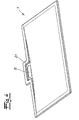
- the Fig. 1 shows a sanitary arrangement in the form of a floor-level shower, which has a shower tray 1.
- the shower tray 1 is according to a preferred embodiment of the invention of sanitary acrylic or steel enamel, wherein the top of the tub body forms the immediately to be entered by a user surface.
- the shower tray 1 is covered in the context of the invention with other material, such as tiles. It can also be seen that the shower tray 1 has a rectangular base and drops towards the middle.
- the shower tray 1 extends into the wall or pretext 4, wherein the shower tray 1 has a drain opening 5 in the hidden area for a user. Since the drainage opening 5 is not visible to a user, this can also have an elongated shape and does not need to be covered.
- a one-piece, contiguous shower tray 1 is provided, which has a drain opening 5 only within its base.
- the shower tray 1 is shaped so that water is always guided in the direction of the drain opening 5 and the shower tray can only leave there.
- it must be ensured that not the entire tub, that is the entire shower tray 1, overflows.
- a comparatively large drain opening 5 can be provided without any visual impairment, just in the context of the inventive design, a very high drainage capacity is possible.
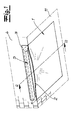
- Fig. 2 The details of the sanitary arrangement according to the invention result from the in Fig. 2 shown section along the line AA, with a middle portion of this section is not shown for reasons of clarity.
- the Fig. 2 is to be understood that the shower tray, starting from its the wall or pretext 4 opposite side evenly along the section line AA to the drain opening 5 drops.
- a cavity 6 is formed within the wall mounted on a behind wall surface pretext 4. Furthermore, in the hidden area below the cavity 6 is a purely schematic indicated drain device 7 connected from below to the drain hole 5 formed in the shower tray 1. The drain device usually has a siphon not shown in detail. Suitable drain devices 7 are known from practice.
- a hood 8 is arranged made of waterproof material.
- the hood 8 can be made of the same material as the shower tray 1, so in particular steel enamel or plumbing acrylic. In addition, however, stainless steel or another waterproof and water-resistant material is suitable.
- the already in the Fig. 1 to be recognized cover 3 is in accordance with Fig. 2 attached by hinges 9 to the hood 8.
- the hinges 9 have a scissor mechanism, which keeps the cover 3 pivoted about a horizontal pivot axis in the open position.
- means may be provided in the form of springs or pressure piston, which support a lifting of the cover 3.
- the shower tray 1 runs on its opposite side of the front wall 4 at ground level into an adjacent bottom surface 11.
- the remaining edges of the shower tray 1 have a different degree of curved S-shape. It is thereby achieved that the shower tray 1 has a raised edge opposite the region of the drain opening 5 on its side running within the wall or wall 4 and on its sides extending away from the wall or wall 4.
- a flat portion 10 is provided, resulting from the flat portion 10 in the direction of the center of the shower tray 1, a significant S-shaped curve.
- the S-shape is steep, while at the wegerumblenden of the wall or pretext Pages for optical reasons, a flat course is provided.
- a free space is provided in the shower tray 1 in a particularly advantageous manner, which can be used to arrange further technical equipment E, which is purely schematic in the Fig. 2 are indicated.
- the technical equipment E can be provided for example for sound, ventilation, heating, scenting, Bewebung or cleaning.
- the measures mentioned can be provided individually or in any combination.
- a recess 12 is formed in the bottom surface 11 corresponding to the shape of the shower tray 1.
- a shower tray support 13 is arranged, which carries the shower tray 1.
- the shower tray support 13 has according to the preferred embodiment illustrated feet 14 and a frame of profile pieces 15.
- the profile pieces 15 in a cross section a support area 16 for the shower tray 1 and for the attachment of the feet 14 a C-shaped groove portion, the feet 14 are attached via head elements 17 to the profile pieces 15 and wherein the head elements 17th are each arranged laterally on an associated profile piece 15 and engage with a holding extension in a slot of the laterally open groove area.
- the profile pieces 15 have an upwardly open channel 18 on their outer side in the mounted state.
- a shower tray support 13 in particular a described shower tray support 13 with feet 14 and profile pieces 15 is not only a simple and accurate installation possible. Rather, the shower tray 1 can also be easily replaced.
- the channel 18 of the profile pieces 15 bent ends 19 of the shower tray and within the cavity 6 also receives a lower edge of the hood 8. In the region of the channel 18, a secure sealing of the sections inserted there is possible. In addition, certain amounts of moisture still accumulating from the gutter 18 can be absorbed.
- connection of the hood 8 to the shower tray 1 and the profile piece 15 is exactly like the connection of the tub body 1 and the profile pieces 15 to the adjacent floor or the wall with a suitable, usually elastic sealing material 20. It is alternatively possible, the hood 8 with the shower tray support 13 to weld.
- the Fig. 3 shows a further embodiment with two sanitary orders.
- the first in the Fig. 3 shown sanitary arrangement is as previously described designed as a floor-level shower.
- a clearly formed edge can also be provided instead of a very soft, continuous transition to the edges projecting away from the wall or wall 4. This is achieved by providing a steeper S-shape at these edges.
- the shower tray 1 made of steel enamel, however, there are certain restrictions with respect to the bends and radii through the sheet metal forming process.
- the second in the Fig. 3 shown sanitary arrangement is designed as a sink.
- a tub body 1 is provided, which in the Wall or pretext 4 extends into it.
- the tub body 1 is not supported down, but is completely fixed with a suitable attitude within the wall or pretext 4.
- the Fig. 4 shows an alternative embodiment of the shower tray 1, wherein in the region of the drain opening 5, the shower tray has a lateral bulge 21 which extends in the mounted state in the wall or pretext 4 inside.
Landscapes
- Engineering & Computer Science (AREA)
- Health & Medical Sciences (AREA)
- Public Health (AREA)
- Life Sciences & Earth Sciences (AREA)
- Hydrology & Water Resources (AREA)
- Water Supply & Treatment (AREA)
- Environmental & Geological Engineering (AREA)
- Epidemiology (AREA)
- General Health & Medical Sciences (AREA)
- Residential Or Office Buildings (AREA)
- Bathtubs, Showers, And Their Attachments (AREA)
- Sink And Installation For Waste Water (AREA)
Claims (13)
- Ensemble sanitaire, avec une paroi ou une avant-paroi (4) comportant un espace creux (6), un bac à douche (1) et un dispositif d'évacuation (7) agencé dans l'épaisseur de paroi ou l'épaisseur d'avant-paroi (4) et raccordé au bac à douche (1), dans lequel le bac à douche (1) s'étend dans la paroi ou l'avant-paroi (4) et le dispositif d'évacuation (7) est raccordé à une ouverture d'évacuation (5) formée dans le bac à douche (1) et agencée à l'intérieur de l'épaisseur de paroi ou de l'épaisseur d'avant-paroi.
- Ensemble sanitaire selon la revendication 1, caractérisé en ce que le bac à douche (1) s'étend au-dessus du dispositif d'évacuation (7) dans la paroi ou l'avant-paroi (4), dans lequel le dispositif d'évacuation (7) est raccordé à l'ouverture d'évacuation (5) par en-dessous.
- Ensemble sanitaire selon la revendication 1 ou 2, caractérisé en ce que sur un côté s'étendant à l'intérieur de la paroi ou de l'avant-paroi (4) et sur au moins une partie des côtés s'étendant à distance de la paroi ou de l'avant-paroi (4), le bac à douche (1) comporte un bord surélevé par rapport à la région entourant l'ouverture d'évacuation (5).
- Ensemble sanitaire selon la revendication 3, caractérisé en ce qu'à partir du bord surélevé, il est prévu un tracé en forme de S en direction du milieu du bac à douche (1) avec une section plane (10).
- Ensemble sanitaire selon l'une des revendications 1 à 4, caractérisé en ce que le bac à douche (1) se termine de façon plane d'un côté opposé à une paroi ou une avant-paroi (4).
- Ensemble sanitaire selon l'une des revendications 1 à 5, caractérisé en ce que le bac à douche (1) est constitué d'acier émaillé ou d'acrylique sanitaire.
- Ensemble sanitaire selon l'une des revendications 1 à 6, caractérisé en ce que dans l'espace creux (6) de la paroi ou de l'avant-paroi (4), une coiffe (8) constituée d'un matériau étanche à l'eau est agencée au-dessus du bac à douche (1) et du dispositif d'évacuation (7).
- Ensemble sanitaire selon l'une des revendications 1 à 7, caractérisé en ce que la paroi ou l'avant-paroi (4) comporte un couvercle (3) au-dessus du bac à douche (1), dans lequel au moins une fente (2) est formée entre le couvercle (3) et le bac à douche (1).
- Ensemble sanitaire selon l'une des revendications 1 à 8, caractérisé en ce que des installations techniques (E) sont prévues dans l'espace creux (6), en particulier pour l'aération et/ou le chauffage et/ou la sonorisation et/ou la diffusion de parfum et/ou la diffusion de brouillard ou de vapeur dans l'ensemble sanitaire.
- Ensemble sanitaire selon l'une des revendications 1 à 9, caractérisé en ce que le bac à douche (1) est agencé sur un support de bac à douche (13).
- Ensemble sanitaire selon la revendication 10, caractérisé en ce que le bac à douche (1) comporte des pieds (14) et un cadre constitué de pièces de profilé (15).
- Ensemble sanitaire selon la revendication 11, caractérisé en ce que les pièces de profilé (15) comportent une gouttière (18) ouverte vers le haut.
- Ensemble sanitaire selon l'une des revendications 1 à 12, caractérisé en ce que le bac à douche (1) s'étend dans la paroi ou l'avant-paroi (4) avec une échancrure latérale (21).
Priority Applications (1)
| Application Number | Priority Date | Filing Date | Title |
|---|---|---|---|
| EP13151731.0A EP2584107B1 (fr) | 2011-01-26 | 2012-01-23 | Agencement sanitaire |
Applications Claiming Priority (1)
| Application Number | Priority Date | Filing Date | Title |
|---|---|---|---|
| DE201110000342 DE102011000342A1 (de) | 2011-01-26 | 2011-01-26 | Sanitäranordnung, insbesondere bodengleiche Dusche |
Related Child Applications (2)
| Application Number | Title | Priority Date | Filing Date |
|---|---|---|---|
| EP13151731.0A Division EP2584107B1 (fr) | 2011-01-26 | 2012-01-23 | Agencement sanitaire |
| EP13151731.0 Division-Into | 2013-01-17 |
Publications (2)
| Publication Number | Publication Date |
|---|---|
| EP2481332A1 EP2481332A1 (fr) | 2012-08-01 |
| EP2481332B1 true EP2481332B1 (fr) | 2013-09-25 |
Family
ID=44312711
Family Applications (2)
| Application Number | Title | Priority Date | Filing Date |
|---|---|---|---|
| EP20120152148 Not-in-force EP2481332B1 (fr) | 2011-01-26 | 2012-01-23 | Dispositif sanitaire, notamment un bac de douche plain-pied |
| EP13151731.0A Not-in-force EP2584107B1 (fr) | 2011-01-26 | 2012-01-23 | Agencement sanitaire |
Family Applications After (1)
| Application Number | Title | Priority Date | Filing Date |
|---|---|---|---|
| EP13151731.0A Not-in-force EP2584107B1 (fr) | 2011-01-26 | 2012-01-23 | Agencement sanitaire |
Country Status (3)
| Country | Link |
|---|---|
| EP (2) | EP2481332B1 (fr) |
| DE (2) | DE102011000342A1 (fr) |
| ES (2) | ES2508215T3 (fr) |
Cited By (1)
| Publication number | Priority date | Publication date | Assignee | Title |
|---|---|---|---|---|
| DE102016118031A1 (de) | 2016-09-23 | 2018-03-29 | Franz Kaldewei Gmbh & Co. Kg | Duschanordnung sowie Verfahren zur Herstellung und Montage der Duschanordnung |
Families Citing this family (14)
| Publication number | Priority date | Publication date | Assignee | Title |
|---|---|---|---|---|
| DE102011051496B4 (de) | 2011-07-01 | 2013-04-04 | Stephan Wedi | Überbausystem für einen im Bodenbereich befindlichen Ablauf |
| DE102012102929B4 (de) | 2012-04-04 | 2021-12-30 | Franz Kaldewei Gmbh & Co. Kg | Sanitäranordnung |
| DE102012021162B4 (de) * | 2012-10-29 | 2015-04-02 | Jung Pumpen Gmbh | Bodenabflussvorrichtung |
| DE102012111579C5 (de) * | 2012-11-29 | 2025-02-13 | Bette Gmbh & Co. Kg | Sanitärwanne und Wanneninstallation |
| US9462916B2 (en) | 2013-05-09 | 2016-10-11 | Kohler Co. | Shower receptor |
| DE102013105954B3 (de) | 2013-06-07 | 2014-09-04 | Leszek Sliwa | Waschtisch-Anordnung |
| DE202013011703U1 (de) | 2013-07-22 | 2014-03-19 | Kunststofftechnik Schedel Gmbh | Duschplatzanordnung |
| DE202014100696U1 (de) | 2014-02-17 | 2014-02-24 | Sliwa Leszek | Sanitäreinrichtung |
| GB2560009B (en) * | 2017-02-24 | 2019-10-16 | Kohler Mira Ltd | Shower waste |
| CN207376728U (zh) * | 2017-10-25 | 2018-05-18 | 陈凯华 | 一种带有隐形下水装置的洗脸台 |
| DE102018120781A1 (de) | 2018-03-05 | 2019-09-05 | Franz Kaldewei Gmbh & Co. Kg | Duschinstallation sowie Verfahren zur Bildung einer Duschinstallation |
| DK3546664T3 (da) * | 2018-03-29 | 2022-07-11 | Geberit Int Ag | Vaskebord |
| DE102023117213A1 (de) | 2023-06-29 | 2025-01-02 | Franz Kaldewei Gmbh & Co. Kg | Sanitärbodeneinrichtung und Sanitärbodeninstallation |
| IT202400003715A1 (it) * | 2024-02-21 | 2025-08-21 | Gianluca Castagnari | Lavabo perfezionato. |
Family Cites Families (17)
| Publication number | Priority date | Publication date | Assignee | Title |
|---|---|---|---|---|
| US3457568A (en) * | 1966-06-27 | 1969-07-29 | Joseph A Amatruda | Shower receptors and the like |
| US5911518A (en) * | 1998-05-04 | 1999-06-15 | Eagle Natural Stone | Shower bath and drain |
| DE20209167U1 (de) | 2002-06-12 | 2002-10-17 | Alape Adolf Lamprecht GmbH & Co. KG, 38644 Goslar | Waschbecken |
| DE102005011790B3 (de) | 2005-03-11 | 2006-11-23 | Franz Kaldewei Gmbh & Co Kg | Sanitärwanne |
| ES2299295B1 (es) * | 2005-05-25 | 2009-04-01 | Jose Fernando Regalado Barroso | Metodo para la realizacion de un sanitario tal como lavabo o plato de ducha, y lavabo o plato de ducha obtenido por dicho metodo. |
| DE202006010243U1 (de) * | 2006-07-01 | 2007-11-08 | Bette Gmbh & Co. Kg | Duschwannenkonstruktion |
| DE102007010625B4 (de) * | 2007-03-02 | 2011-04-14 | Munch, Paul-Jean | Duschwanne für den bodengleichen Einbau |
| DE102007010915B4 (de) * | 2007-03-05 | 2025-12-31 | Alape Gmbh | Waschplatzeinrichtung |
| DE202007006360U1 (de) * | 2007-05-03 | 2007-07-12 | Munch, Paul-Jean | Duschwanne oder Duschplateau |
| DK2159336T3 (da) * | 2007-06-29 | 2013-07-01 | Geberit Int Ag | Anvendelse af et gulvafløb |
| DE102008046671A1 (de) * | 2007-11-30 | 2009-06-04 | Dallmer Gmbh & Co. Kg | Ablaufvorrichtung |
| ITBO20080154A1 (it) * | 2008-03-10 | 2009-09-11 | Mario Nanni Progettista S R L | Lavandino |
| DE102009009989A1 (de) * | 2009-02-23 | 2010-08-26 | Dallmer Gmbh & Co. Kg | Ablaufvorrichtung |
| DE202009017854U1 (de) * | 2009-03-09 | 2010-06-17 | Mepa - Pauli Und Menden Gmbh | Duschrinnenanordnung für Wandeinbau |
| DE102009055934A1 (de) * | 2009-11-27 | 2011-06-01 | Stephan Wedi | Duschablaufsystem und Aufnahmeelement für ein Duschablaufsystem |
| DE202009017155U1 (de) * | 2009-12-19 | 2010-04-01 | Geberit International Ag, Jona | Bodenablauf für eine sanitäre Installation |
| PL2333171T3 (pl) * | 2009-12-07 | 2013-08-30 | Geberit Int Ag | Odpływ podłogowy dla instalacji sanitarnej, oraz sposób instalacji takiego odpływu podłogowego |
-
2011
- 2011-01-26 DE DE201110000342 patent/DE102011000342A1/de not_active Withdrawn
- 2011-02-08 DE DE202011000278U patent/DE202011000278U1/de not_active Expired - Lifetime
-
2012
- 2012-01-23 EP EP20120152148 patent/EP2481332B1/fr not_active Not-in-force
- 2012-01-23 ES ES13151731.0T patent/ES2508215T3/es active Active
- 2012-01-23 ES ES12152148T patent/ES2440343T3/es active Active
- 2012-01-23 EP EP13151731.0A patent/EP2584107B1/fr not_active Not-in-force
Cited By (1)
| Publication number | Priority date | Publication date | Assignee | Title |
|---|---|---|---|---|
| DE102016118031A1 (de) | 2016-09-23 | 2018-03-29 | Franz Kaldewei Gmbh & Co. Kg | Duschanordnung sowie Verfahren zur Herstellung und Montage der Duschanordnung |
Also Published As
| Publication number | Publication date |
|---|---|
| DE102011000342A1 (de) | 2012-07-26 |
| ES2440343T3 (es) | 2014-01-28 |
| DE202011000278U1 (de) | 2011-06-01 |
| ES2508215T3 (es) | 2014-10-16 |
| EP2481332A1 (fr) | 2012-08-01 |
| EP2584107B1 (fr) | 2014-07-02 |
| EP2584107A1 (fr) | 2013-04-24 |
Similar Documents
| Publication | Publication Date | Title |
|---|---|---|
| EP2481332B1 (fr) | Dispositif sanitaire, notamment un bac de douche plain-pied | |
| EP1908887B1 (fr) | Siphon de sol en particulier sous forme d'une rainure de douche | |
| EP2009187B1 (fr) | Installation sanitaire dotée d'un siphon de sol tout comme procédé de montage d'une telle installation sanitaire | |
| EP2479353B1 (fr) | Cuve sanitaire | |
| DE202011051140U1 (de) | Abdeckkasten für ein Duschablaufsystem | |
| DE202014007357U1 (de) | Bodenablauf mit Dichtungsmatte | |
| DE202012103906U1 (de) | Duschwannenanordnung, insbesondere bodengleiche Dusche | |
| EP1801300A2 (fr) | Bouche d'égout en forme d'une gouttière avec ouverture d'inspection | |
| EP1779754A1 (fr) | Planche de douche avec système de canal d'écoulement | |
| CH706368B1 (de) | Sanitäranordnung. | |
| DE102007060444B4 (de) | Bodenablauf | |
| EP2258905B1 (fr) | Écoulement, notamment pour des dispositifs sanitaires | |
| DE202014007391U1 (de) | Bodenablauf mit Einlauftrichter | |
| EP1813731A2 (fr) | Evier de cuisine, en particulier pour des applications domestiques | |
| DE102012106924A1 (de) | Ablaufanordnung | |
| DE202014007356U1 (de) | Wasserablauf mit Einsatz | |
| DE102006051130B4 (de) | Ablaufvorrichtung für die zumindest teilweise Einbringung in einen Boden eines Raumes | |
| DE202011004001U1 (de) | Ablaufanordnung | |
| DE102021103470A1 (de) | Sanitärbodenelement und Kombination eines Sanitärbodenelements mit einer Wandablaufvorrichtung | |
| EP2995730B1 (fr) | Bouche d'égout avec un entonnoir d'entrée | |
| DE202017104903U1 (de) | Rostdeckel für Ablaufrinne | |
| EP4012125B1 (fr) | Élément inférieur sanitaire et combinaison d'un élément inférieur sanitaire avec un dispositif mural d'évacuation | |
| EP4461893A1 (fr) | Caniveau d'écoulement embouti | |
| DE202007019551U1 (de) | Wandablauf 3 | |
| EP4461891A1 (fr) | Bouche d'égout avec bride variable |
Legal Events
| Date | Code | Title | Description |
|---|---|---|---|
| PUAI | Public reference made under article 153(3) epc to a published international application that has entered the european phase |
Free format text: ORIGINAL CODE: 0009012 |
|
| AK | Designated contracting states |
Kind code of ref document: A1 Designated state(s): AL AT BE BG CH CY CZ DE DK EE ES FI FR GB GR HR HU IE IS IT LI LT LU LV MC MK MT NL NO PL PT RO RS SE SI SK SM TR |
|
| AX | Request for extension of the european patent |
Extension state: BA ME |
|
| 17P | Request for examination filed |
Effective date: 20121004 |
|
| GRAP | Despatch of communication of intention to grant a patent |
Free format text: ORIGINAL CODE: EPIDOSNIGR1 |
|
| RIC1 | Information provided on ipc code assigned before grant |
Ipc: A47K 3/40 20060101AFI20130321BHEP Ipc: E03F 5/04 20060101ALI20130321BHEP |
|
| INTG | Intention to grant announced |
Effective date: 20130417 |
|
| GRAS | Grant fee paid |
Free format text: ORIGINAL CODE: EPIDOSNIGR3 |
|
| GRAA | (expected) grant |
Free format text: ORIGINAL CODE: 0009210 |
|
| AK | Designated contracting states |
Kind code of ref document: B1 Designated state(s): AL AT BE BG CH CY CZ DE DK EE ES FI FR GB GR HR HU IE IS IT LI LT LU LV MC MK MT NL NO PL PT RO RS SE SI SK SM TR |
|
| REG | Reference to a national code |
Ref country code: GB Ref legal event code: FG4D Free format text: NOT ENGLISH |
|
| REG | Reference to a national code |
Ref country code: CH Ref legal event code: EP |
|
| REG | Reference to a national code |
Ref country code: AT Ref legal event code: REF Ref document number: 633395 Country of ref document: AT Kind code of ref document: T Effective date: 20131015 |
|
| REG | Reference to a national code |
Ref country code: IE Ref legal event code: FG4D Free format text: LANGUAGE OF EP DOCUMENT: GERMAN |
|
| REG | Reference to a national code |
Ref country code: DE Ref legal event code: R096 Ref document number: 502012000137 Country of ref document: DE Effective date: 20131121 |
|
| REG | Reference to a national code |
Ref country code: CH Ref legal event code: NV Representative=s name: KELLER AND PARTNER PATENTANWAELTE AG, CH |
|
| REG | Reference to a national code |
Ref country code: ES Ref legal event code: FG2A Ref document number: 2440343 Country of ref document: ES Kind code of ref document: T3 Effective date: 20140128 |
|
| PG25 | Lapsed in a contracting state [announced via postgrant information from national office to epo] |
Ref country code: SE Free format text: LAPSE BECAUSE OF FAILURE TO SUBMIT A TRANSLATION OF THE DESCRIPTION OR TO PAY THE FEE WITHIN THE PRESCRIBED TIME-LIMIT Effective date: 20130925 Ref country code: NO Free format text: LAPSE BECAUSE OF FAILURE TO SUBMIT A TRANSLATION OF THE DESCRIPTION OR TO PAY THE FEE WITHIN THE PRESCRIBED TIME-LIMIT Effective date: 20131225 Ref country code: HR Free format text: LAPSE BECAUSE OF FAILURE TO SUBMIT A TRANSLATION OF THE DESCRIPTION OR TO PAY THE FEE WITHIN THE PRESCRIBED TIME-LIMIT Effective date: 20130925 Ref country code: LT Free format text: LAPSE BECAUSE OF FAILURE TO SUBMIT A TRANSLATION OF THE DESCRIPTION OR TO PAY THE FEE WITHIN THE PRESCRIBED TIME-LIMIT Effective date: 20130925 |
|
| REG | Reference to a national code |
Ref country code: NL Ref legal event code: VDEP Effective date: 20130925 |
|
| REG | Reference to a national code |
Ref country code: LT Ref legal event code: MG4D |
|
| PG25 | Lapsed in a contracting state [announced via postgrant information from national office to epo] |
Ref country code: SI Free format text: LAPSE BECAUSE OF FAILURE TO SUBMIT A TRANSLATION OF THE DESCRIPTION OR TO PAY THE FEE WITHIN THE PRESCRIBED TIME-LIMIT Effective date: 20130925 Ref country code: RS Free format text: LAPSE BECAUSE OF FAILURE TO SUBMIT A TRANSLATION OF THE DESCRIPTION OR TO PAY THE FEE WITHIN THE PRESCRIBED TIME-LIMIT Effective date: 20130925 Ref country code: FI Free format text: LAPSE BECAUSE OF FAILURE TO SUBMIT A TRANSLATION OF THE DESCRIPTION OR TO PAY THE FEE WITHIN THE PRESCRIBED TIME-LIMIT Effective date: 20130925 Ref country code: LV Free format text: LAPSE BECAUSE OF FAILURE TO SUBMIT A TRANSLATION OF THE DESCRIPTION OR TO PAY THE FEE WITHIN THE PRESCRIBED TIME-LIMIT Effective date: 20130925 |
|
| PG25 | Lapsed in a contracting state [announced via postgrant information from national office to epo] |
Ref country code: NL Free format text: LAPSE BECAUSE OF FAILURE TO SUBMIT A TRANSLATION OF THE DESCRIPTION OR TO PAY THE FEE WITHIN THE PRESCRIBED TIME-LIMIT Effective date: 20130925 Ref country code: IS Free format text: LAPSE BECAUSE OF FAILURE TO SUBMIT A TRANSLATION OF THE DESCRIPTION OR TO PAY THE FEE WITHIN THE PRESCRIBED TIME-LIMIT Effective date: 20140125 Ref country code: EE Free format text: LAPSE BECAUSE OF FAILURE TO SUBMIT A TRANSLATION OF THE DESCRIPTION OR TO PAY THE FEE WITHIN THE PRESCRIBED TIME-LIMIT Effective date: 20130925 Ref country code: CZ Free format text: LAPSE BECAUSE OF FAILURE TO SUBMIT A TRANSLATION OF THE DESCRIPTION OR TO PAY THE FEE WITHIN THE PRESCRIBED TIME-LIMIT Effective date: 20130925 Ref country code: RO Free format text: LAPSE BECAUSE OF FAILURE TO SUBMIT A TRANSLATION OF THE DESCRIPTION OR TO PAY THE FEE WITHIN THE PRESCRIBED TIME-LIMIT Effective date: 20130925 Ref country code: SK Free format text: LAPSE BECAUSE OF FAILURE TO SUBMIT A TRANSLATION OF THE DESCRIPTION OR TO PAY THE FEE WITHIN THE PRESCRIBED TIME-LIMIT Effective date: 20130925 |
|
| PG25 | Lapsed in a contracting state [announced via postgrant information from national office to epo] |
Ref country code: PL Free format text: LAPSE BECAUSE OF FAILURE TO SUBMIT A TRANSLATION OF THE DESCRIPTION OR TO PAY THE FEE WITHIN THE PRESCRIBED TIME-LIMIT Effective date: 20130925 Ref country code: CY Free format text: LAPSE BECAUSE OF FAILURE TO SUBMIT A TRANSLATION OF THE DESCRIPTION OR TO PAY THE FEE WITHIN THE PRESCRIBED TIME-LIMIT Effective date: 20130925 |
|
| PLBI | Opposition filed |
Free format text: ORIGINAL CODE: 0009260 |
|
| PG25 | Lapsed in a contracting state [announced via postgrant information from national office to epo] |
Ref country code: PT Free format text: LAPSE BECAUSE OF FAILURE TO SUBMIT A TRANSLATION OF THE DESCRIPTION OR TO PAY THE FEE WITHIN THE PRESCRIBED TIME-LIMIT Effective date: 20140127 |
|
| PLAB | Opposition data, opponent's data or that of the opponent's representative modified |
Free format text: ORIGINAL CODE: 0009299OPPO |
|
| 26 | Opposition filed |
Opponent name: MEPA - PAULI UND MENDEN GMBH Effective date: 20140625 Opponent name: WEDI GMBH Effective date: 20140624 |
|
| BERE | Be: lapsed |
Owner name: FRANZ KALDEWEI G.M.B.H. & CO. KG Effective date: 20140131 |
|
| PLAX | Notice of opposition and request to file observation + time limit sent |
Free format text: ORIGINAL CODE: EPIDOSNOBS2 |
|
| R26 | Opposition filed (corrected) |
Opponent name: MEPA - PAULI UND MENDEN GMBH Effective date: 20140625 |
|
| PG25 | Lapsed in a contracting state [announced via postgrant information from national office to epo] |
Ref country code: LU Free format text: LAPSE BECAUSE OF FAILURE TO SUBMIT A TRANSLATION OF THE DESCRIPTION OR TO PAY THE FEE WITHIN THE PRESCRIBED TIME-LIMIT Effective date: 20140123 |
|
| REG | Reference to a national code |
Ref country code: DE Ref legal event code: R026 Ref document number: 502012000137 Country of ref document: DE Effective date: 20140624 |
|
| PG25 | Lapsed in a contracting state [announced via postgrant information from national office to epo] |
Ref country code: DK Free format text: LAPSE BECAUSE OF FAILURE TO SUBMIT A TRANSLATION OF THE DESCRIPTION OR TO PAY THE FEE WITHIN THE PRESCRIBED TIME-LIMIT Effective date: 20130925 |
|
| REG | Reference to a national code |
Ref country code: IE Ref legal event code: MM4A |
|
| PLAF | Information modified related to communication of a notice of opposition and request to file observations + time limit |
Free format text: ORIGINAL CODE: EPIDOSCOBS2 |
|
| REG | Reference to a national code |
Ref country code: FR Ref legal event code: PLFP Year of fee payment: 4 |
|
| PG25 | Lapsed in a contracting state [announced via postgrant information from national office to epo] |
Ref country code: IE Free format text: LAPSE BECAUSE OF NON-PAYMENT OF DUE FEES Effective date: 20140123 |
|
| PLBB | Reply of patent proprietor to notice(s) of opposition received |
Free format text: ORIGINAL CODE: EPIDOSNOBS3 |
|
| REG | Reference to a national code |
Ref country code: CH Ref legal event code: PCAR Free format text: NEW ADDRESS: EIGERSTRASSE 2 POSTFACH, 3000 BERN 14 (CH) |
|
| PG25 | Lapsed in a contracting state [announced via postgrant information from national office to epo] |
Ref country code: MC Free format text: LAPSE BECAUSE OF FAILURE TO SUBMIT A TRANSLATION OF THE DESCRIPTION OR TO PAY THE FEE WITHIN THE PRESCRIBED TIME-LIMIT Effective date: 20130925 |
|
| PLAB | Opposition data, opponent's data or that of the opponent's representative modified |
Free format text: ORIGINAL CODE: 0009299OPPO |
|
| R26 | Opposition filed (corrected) |
Opponent name: WEDI GMBH Effective date: 20140624 |
|
| PG25 | Lapsed in a contracting state [announced via postgrant information from national office to epo] |
Ref country code: BE Free format text: LAPSE BECAUSE OF NON-PAYMENT OF DUE FEES Effective date: 20150131 |
|
| PLAB | Opposition data, opponent's data or that of the opponent's representative modified |
Free format text: ORIGINAL CODE: 0009299OPPO |
|
| R26 | Opposition filed (corrected) |
Opponent name: WEDI GMBH Effective date: 20140624 |
|
| REG | Reference to a national code |
Ref country code: FR Ref legal event code: PLFP Year of fee payment: 5 |
|
| PG25 | Lapsed in a contracting state [announced via postgrant information from national office to epo] |
Ref country code: MT Free format text: LAPSE BECAUSE OF FAILURE TO SUBMIT A TRANSLATION OF THE DESCRIPTION OR TO PAY THE FEE WITHIN THE PRESCRIBED TIME-LIMIT Effective date: 20130925 |
|
| PG25 | Lapsed in a contracting state [announced via postgrant information from national office to epo] |
Ref country code: SM Free format text: LAPSE BECAUSE OF FAILURE TO SUBMIT A TRANSLATION OF THE DESCRIPTION OR TO PAY THE FEE WITHIN THE PRESCRIBED TIME-LIMIT Effective date: 20130925 |
|
| REG | Reference to a national code |
Ref country code: DE Ref legal event code: R100 Ref document number: 502012000137 Country of ref document: DE |
|
| PG25 | Lapsed in a contracting state [announced via postgrant information from national office to epo] |
Ref country code: GR Free format text: LAPSE BECAUSE OF FAILURE TO SUBMIT A TRANSLATION OF THE DESCRIPTION OR TO PAY THE FEE WITHIN THE PRESCRIBED TIME-LIMIT Effective date: 20130925 Ref country code: BG Free format text: LAPSE BECAUSE OF FAILURE TO SUBMIT A TRANSLATION OF THE DESCRIPTION OR TO PAY THE FEE WITHIN THE PRESCRIBED TIME-LIMIT Effective date: 20130925 |
|
| PLCK | Communication despatched that opposition was rejected |
Free format text: ORIGINAL CODE: EPIDOSNREJ1 |
|
| PG25 | Lapsed in a contracting state [announced via postgrant information from national office to epo] |
Ref country code: HU Free format text: LAPSE BECAUSE OF FAILURE TO SUBMIT A TRANSLATION OF THE DESCRIPTION OR TO PAY THE FEE WITHIN THE PRESCRIBED TIME-LIMIT; INVALID AB INITIO Effective date: 20120123 Ref country code: TR Free format text: LAPSE BECAUSE OF FAILURE TO SUBMIT A TRANSLATION OF THE DESCRIPTION OR TO PAY THE FEE WITHIN THE PRESCRIBED TIME-LIMIT Effective date: 20130925 Ref country code: BE Free format text: LAPSE BECAUSE OF FAILURE TO SUBMIT A TRANSLATION OF THE DESCRIPTION OR TO PAY THE FEE WITHIN THE PRESCRIBED TIME-LIMIT Effective date: 20140131 |
|
| PLBN | Opposition rejected |
Free format text: ORIGINAL CODE: 0009273 |
|
| STAA | Information on the status of an ep patent application or granted ep patent |
Free format text: STATUS: OPPOSITION REJECTED |
|
| 27O | Opposition rejected |
Effective date: 20160530 |
|
| REG | Reference to a national code |
Ref country code: FR Ref legal event code: PLFP Year of fee payment: 6 |
|
| REG | Reference to a national code |
Ref country code: FR Ref legal event code: PLFP Year of fee payment: 7 |
|
| PG25 | Lapsed in a contracting state [announced via postgrant information from national office to epo] |
Ref country code: MK Free format text: LAPSE BECAUSE OF FAILURE TO SUBMIT A TRANSLATION OF THE DESCRIPTION OR TO PAY THE FEE WITHIN THE PRESCRIBED TIME-LIMIT Effective date: 20130925 |
|
| PG25 | Lapsed in a contracting state [announced via postgrant information from national office to epo] |
Ref country code: AL Free format text: LAPSE BECAUSE OF FAILURE TO SUBMIT A TRANSLATION OF THE DESCRIPTION OR TO PAY THE FEE WITHIN THE PRESCRIBED TIME-LIMIT Effective date: 20130925 |
|
| PGFP | Annual fee paid to national office [announced via postgrant information from national office to epo] |
Ref country code: AT Payment date: 20200122 Year of fee payment: 9 Ref country code: IT Payment date: 20200131 Year of fee payment: 9 Ref country code: ES Payment date: 20200221 Year of fee payment: 9 Ref country code: GB Payment date: 20200124 Year of fee payment: 9 |
|
| PGFP | Annual fee paid to national office [announced via postgrant information from national office to epo] |
Ref country code: FR Payment date: 20200121 Year of fee payment: 9 |
|
| REG | Reference to a national code |
Ref country code: CH Ref legal event code: PFA Owner name: FRANZ KALDEWEI GMBH AND CO. KG, DE Free format text: FORMER OWNER: FRANZ KALDEWEI GMBH AND CO. KG, DE |
|
| PGFP | Annual fee paid to national office [announced via postgrant information from national office to epo] |
Ref country code: CH Payment date: 20210120 Year of fee payment: 10 |
|
| PGFP | Annual fee paid to national office [announced via postgrant information from national office to epo] |
Ref country code: DE Payment date: 20210115 Year of fee payment: 10 |
|
| REG | Reference to a national code |
Ref country code: AT Ref legal event code: MM01 Ref document number: 633395 Country of ref document: AT Kind code of ref document: T Effective date: 20210123 |
|
| GBPC | Gb: european patent ceased through non-payment of renewal fee |
Effective date: 20210123 |
|
| PG25 | Lapsed in a contracting state [announced via postgrant information from national office to epo] |
Ref country code: AT Free format text: LAPSE BECAUSE OF NON-PAYMENT OF DUE FEES Effective date: 20210123 Ref country code: FR Free format text: LAPSE BECAUSE OF NON-PAYMENT OF DUE FEES Effective date: 20210131 |
|
| PG25 | Lapsed in a contracting state [announced via postgrant information from national office to epo] |
Ref country code: GB Free format text: LAPSE BECAUSE OF NON-PAYMENT OF DUE FEES Effective date: 20210123 |
|
| REG | Reference to a national code |
Ref country code: ES Ref legal event code: FD2A Effective date: 20220427 |
|
| PG25 | Lapsed in a contracting state [announced via postgrant information from national office to epo] |
Ref country code: IT Free format text: LAPSE BECAUSE OF NON-PAYMENT OF DUE FEES Effective date: 20210123 |
|
| PG25 | Lapsed in a contracting state [announced via postgrant information from national office to epo] |
Ref country code: ES Free format text: LAPSE BECAUSE OF NON-PAYMENT OF DUE FEES Effective date: 20210124 |
|
| REG | Reference to a national code |
Ref country code: DE Ref legal event code: R119 Ref document number: 502012000137 Country of ref document: DE |
|
| REG | Reference to a national code |
Ref country code: CH Ref legal event code: PL |
|
| PG25 | Lapsed in a contracting state [announced via postgrant information from national office to epo] |
Ref country code: DE Free format text: LAPSE BECAUSE OF NON-PAYMENT OF DUE FEES Effective date: 20220802 |
|
| PG25 | Lapsed in a contracting state [announced via postgrant information from national office to epo] |
Ref country code: LI Free format text: LAPSE BECAUSE OF NON-PAYMENT OF DUE FEES Effective date: 20220131 Ref country code: CH Free format text: LAPSE BECAUSE OF NON-PAYMENT OF DUE FEES Effective date: 20220131 |