EP2481379B1 - Medizinische kathetervorrichtung - Google Patents
Medizinische kathetervorrichtung Download PDFInfo
- Publication number
- EP2481379B1 EP2481379B1 EP10818533.1A EP10818533A EP2481379B1 EP 2481379 B1 EP2481379 B1 EP 2481379B1 EP 10818533 A EP10818533 A EP 10818533A EP 2481379 B1 EP2481379 B1 EP 2481379B1
- Authority
- EP
- European Patent Office
- Prior art keywords
- catheter
- guide wire
- sheath
- tubular member
- balloon
- Prior art date
- Legal status (The legal status is an assumption and is not a legal conclusion. Google has not performed a legal analysis and makes no representation as to the accuracy of the status listed.)
- Not-in-force
Links
- 230000002792 vascular Effects 0.000 claims description 17
- 238000003780 insertion Methods 0.000 claims description 15
- 230000037431 insertion Effects 0.000 claims description 15
- 229920003002 synthetic resin Polymers 0.000 claims description 12
- 239000000057 synthetic resin Substances 0.000 claims description 12
- 238000002844 melting Methods 0.000 claims description 7
- 230000008018 melting Effects 0.000 claims description 7
- 230000005012 migration Effects 0.000 claims description 5
- 238000013508 migration Methods 0.000 claims description 5
- 239000000463 material Substances 0.000 claims description 3
- 230000002093 peripheral effect Effects 0.000 claims 1
- 238000007789 sealing Methods 0.000 claims 1
- 210000004204 blood vessel Anatomy 0.000 description 29
- 238000002513 implantation Methods 0.000 description 9
- 244000208734 Pisonia aculeata Species 0.000 description 8
- 238000002399 angioplasty Methods 0.000 description 7
- 239000007943 implant Substances 0.000 description 7
- FAPWRFPIFSIZLT-UHFFFAOYSA-M Sodium chloride Chemical compound [Na+].[Cl-] FAPWRFPIFSIZLT-UHFFFAOYSA-M 0.000 description 3
- 230000000694 effects Effects 0.000 description 3
- 239000007788 liquid Substances 0.000 description 3
- 229910052751 metal Inorganic materials 0.000 description 3
- 239000002184 metal Substances 0.000 description 3
- 229920006122 polyamide resin Polymers 0.000 description 3
- 230000001154 acute effect Effects 0.000 description 2
- 239000004621 biodegradable polymer Substances 0.000 description 2
- 229920002988 biodegradable polymer Polymers 0.000 description 2
- 230000017531 blood circulation Effects 0.000 description 2
- 239000002872 contrast media Substances 0.000 description 2
- 210000004351 coronary vessel Anatomy 0.000 description 2
- 238000000034 method Methods 0.000 description 2
- 229920001721 polyimide Polymers 0.000 description 2
- 230000001681 protective effect Effects 0.000 description 2
- 208000037803 restenosis Diseases 0.000 description 2
- 238000003466 welding Methods 0.000 description 2
- 206010061660 Artery dissection Diseases 0.000 description 1
- 208000031481 Pathologic Constriction Diseases 0.000 description 1
- 239000004642 Polyimide Substances 0.000 description 1
- 239000000853 adhesive Substances 0.000 description 1
- 230000001070 adhesive effect Effects 0.000 description 1
- 229910052782 aluminium Inorganic materials 0.000 description 1
- XAGFODPZIPBFFR-UHFFFAOYSA-N aluminium Chemical compound [Al] XAGFODPZIPBFFR-UHFFFAOYSA-N 0.000 description 1
- 238000005452 bending Methods 0.000 description 1
- 210000000013 bile duct Anatomy 0.000 description 1
- 239000008280 blood Substances 0.000 description 1
- 210000004369 blood Anatomy 0.000 description 1
- 230000008602 contraction Effects 0.000 description 1
- 230000006837 decompression Effects 0.000 description 1
- 239000012530 fluid Substances 0.000 description 1
- 239000009719 polyimide resin Substances 0.000 description 1
- 229920000642 polymer Polymers 0.000 description 1
- 229910001220 stainless steel Inorganic materials 0.000 description 1
- 239000010935 stainless steel Substances 0.000 description 1
- 208000037804 stenosis Diseases 0.000 description 1
- 230000036262 stenosis Effects 0.000 description 1
- 210000000626 ureter Anatomy 0.000 description 1
Images



Classifications
-
- A—HUMAN NECESSITIES
- A61—MEDICAL OR VETERINARY SCIENCE; HYGIENE
- A61M—DEVICES FOR INTRODUCING MEDIA INTO, OR ONTO, THE BODY; DEVICES FOR TRANSDUCING BODY MEDIA OR FOR TAKING MEDIA FROM THE BODY; DEVICES FOR PRODUCING OR ENDING SLEEP OR STUPOR
- A61M25/00—Catheters; Hollow probes
- A61M25/01—Introducing, guiding, advancing, emplacing or holding catheters
-
- A—HUMAN NECESSITIES
- A61—MEDICAL OR VETERINARY SCIENCE; HYGIENE
- A61F—FILTERS IMPLANTABLE INTO BLOOD VESSELS; PROSTHESES; DEVICES PROVIDING PATENCY TO, OR PREVENTING COLLAPSING OF, TUBULAR STRUCTURES OF THE BODY, e.g. STENTS; ORTHOPAEDIC, NURSING OR CONTRACEPTIVE DEVICES; FOMENTATION; TREATMENT OR PROTECTION OF EYES OR EARS; BANDAGES, DRESSINGS OR ABSORBENT PADS; FIRST-AID KITS
- A61F2/00—Filters implantable into blood vessels; Prostheses, i.e. artificial substitutes or replacements for parts of the body; Appliances for connecting them with the body; Devices providing patency to, or preventing collapsing of, tubular structures of the body, e.g. stents
- A61F2/95—Instruments specially adapted for placement or removal of stents or stent-grafts
- A61F2/958—Inflatable balloons for placing stents or stent-grafts
-
- A—HUMAN NECESSITIES
- A61—MEDICAL OR VETERINARY SCIENCE; HYGIENE
- A61M—DEVICES FOR INTRODUCING MEDIA INTO, OR ONTO, THE BODY; DEVICES FOR TRANSDUCING BODY MEDIA OR FOR TAKING MEDIA FROM THE BODY; DEVICES FOR PRODUCING OR ENDING SLEEP OR STUPOR
- A61M25/00—Catheters; Hollow probes
- A61M25/01—Introducing, guiding, advancing, emplacing or holding catheters
- A61M25/09—Guide wires
-
- A—HUMAN NECESSITIES
- A61—MEDICAL OR VETERINARY SCIENCE; HYGIENE
- A61F—FILTERS IMPLANTABLE INTO BLOOD VESSELS; PROSTHESES; DEVICES PROVIDING PATENCY TO, OR PREVENTING COLLAPSING OF, TUBULAR STRUCTURES OF THE BODY, e.g. STENTS; ORTHOPAEDIC, NURSING OR CONTRACEPTIVE DEVICES; FOMENTATION; TREATMENT OR PROTECTION OF EYES OR EARS; BANDAGES, DRESSINGS OR ABSORBENT PADS; FIRST-AID KITS
- A61F2/00—Filters implantable into blood vessels; Prostheses, i.e. artificial substitutes or replacements for parts of the body; Appliances for connecting them with the body; Devices providing patency to, or preventing collapsing of, tubular structures of the body, e.g. stents
- A61F2/95—Instruments specially adapted for placement or removal of stents or stent-grafts
- A61F2/958—Inflatable balloons for placing stents or stent-grafts
- A61F2002/9583—Means for holding the stent on the balloon, e.g. using protrusions, adhesives or an outer sleeve
-
- A—HUMAN NECESSITIES
- A61—MEDICAL OR VETERINARY SCIENCE; HYGIENE
- A61F—FILTERS IMPLANTABLE INTO BLOOD VESSELS; PROSTHESES; DEVICES PROVIDING PATENCY TO, OR PREVENTING COLLAPSING OF, TUBULAR STRUCTURES OF THE BODY, e.g. STENTS; ORTHOPAEDIC, NURSING OR CONTRACEPTIVE DEVICES; FOMENTATION; TREATMENT OR PROTECTION OF EYES OR EARS; BANDAGES, DRESSINGS OR ABSORBENT PADS; FIRST-AID KITS
- A61F2250/00—Special features of prostheses classified in groups A61F2/00 - A61F2/26 or A61F2/82 or A61F9/00 or A61F11/00 or subgroups thereof
- A61F2250/0014—Special features of prostheses classified in groups A61F2/00 - A61F2/26 or A61F2/82 or A61F9/00 or A61F11/00 or subgroups thereof having different values of a given property or geometrical feature, e.g. mechanical property or material property, at different locations within the same prosthesis
- A61F2250/0037—Special features of prostheses classified in groups A61F2/00 - A61F2/26 or A61F2/82 or A61F9/00 or A61F11/00 or subgroups thereof having different values of a given property or geometrical feature, e.g. mechanical property or material property, at different locations within the same prosthesis differing in height or in length
-
- A—HUMAN NECESSITIES
- A61—MEDICAL OR VETERINARY SCIENCE; HYGIENE
- A61F—FILTERS IMPLANTABLE INTO BLOOD VESSELS; PROSTHESES; DEVICES PROVIDING PATENCY TO, OR PREVENTING COLLAPSING OF, TUBULAR STRUCTURES OF THE BODY, e.g. STENTS; ORTHOPAEDIC, NURSING OR CONTRACEPTIVE DEVICES; FOMENTATION; TREATMENT OR PROTECTION OF EYES OR EARS; BANDAGES, DRESSINGS OR ABSORBENT PADS; FIRST-AID KITS
- A61F2250/00—Special features of prostheses classified in groups A61F2/00 - A61F2/26 or A61F2/82 or A61F9/00 or A61F11/00 or subgroups thereof
- A61F2250/0058—Additional features; Implant or prostheses properties not otherwise provided for
- A61F2250/0065—Additional features; Implant or prostheses properties not otherwise provided for telescopic
-
- A—HUMAN NECESSITIES
- A61—MEDICAL OR VETERINARY SCIENCE; HYGIENE
- A61M—DEVICES FOR INTRODUCING MEDIA INTO, OR ONTO, THE BODY; DEVICES FOR TRANSDUCING BODY MEDIA OR FOR TAKING MEDIA FROM THE BODY; DEVICES FOR PRODUCING OR ENDING SLEEP OR STUPOR
- A61M25/00—Catheters; Hollow probes
- A61M25/01—Introducing, guiding, advancing, emplacing or holding catheters
- A61M2025/0183—Rapid exchange or monorail catheters
-
- A—HUMAN NECESSITIES
- A61—MEDICAL OR VETERINARY SCIENCE; HYGIENE
- A61M—DEVICES FOR INTRODUCING MEDIA INTO, OR ONTO, THE BODY; DEVICES FOR TRANSDUCING BODY MEDIA OR FOR TAKING MEDIA FROM THE BODY; DEVICES FOR PRODUCING OR ENDING SLEEP OR STUPOR
- A61M25/00—Catheters; Hollow probes
- A61M25/01—Introducing, guiding, advancing, emplacing or holding catheters
- A61M25/06—Body-piercing guide needles or the like
- A61M25/0662—Guide tubes
- A61M2025/0681—Systems with catheter and outer tubing, e.g. sheath, sleeve or guide tube
-
- A—HUMAN NECESSITIES
- A61—MEDICAL OR VETERINARY SCIENCE; HYGIENE
- A61M—DEVICES FOR INTRODUCING MEDIA INTO, OR ONTO, THE BODY; DEVICES FOR TRANSDUCING BODY MEDIA OR FOR TAKING MEDIA FROM THE BODY; DEVICES FOR PRODUCING OR ENDING SLEEP OR STUPOR
- A61M25/00—Catheters; Hollow probes
- A61M25/0021—Catheters; Hollow probes characterised by the form of the tubing
- A61M25/0023—Catheters; Hollow probes characterised by the form of the tubing by the form of the lumen, e.g. cross-section, variable diameter
- A61M25/0026—Multi-lumen catheters with stationary elements
- A61M25/0029—Multi-lumen catheters with stationary elements characterized by features relating to least one lumen located at the middle part of the catheter, e.g. slots, flaps, valves, cuffs, apertures, notches, grooves or rapid exchange ports
Definitions
- the present invention relates to a medical catheter apparatus useful for implanting a vascular stent into a vessel in a living body.
- PTA percutaneous transluminal angioplasty
- a tubular shaped stent is implanted at the site following PTA.
- the stent is in a contracted state when introduced into a blood vessel, and subsequently expanded in diameter so as to be deployed at the intended site scaffolding the vessel wall from its inside.
- the stent to be implanted in a blood vessel is inserted and transported to the intended site in the vessel by using a catheter having a balloon which can be dilated with expansion medium supplied thereto (balloon catheter).
- the contracted stent is mounted onto the balloon provided at the distal portion of the catheter to be inserted into the blood vessel and transported to the intended site together with the balloon.
- the balloon inflation by supplying the expansion medium into it the stent is expanded in diameter, and consequently deployed at the intended site.
- the once expanded stent keeps its expanded state even after the balloon is deflated by removal of the expansion medium, thereby scaffolding the implanted site radially to allow fluid path for humor such as blood in the vessel lumen.
- Implantation of the stent using the above-mentioned catheter follows the procedure below.
- a guide wire previously inserted in a catheter is inserted into a blood vessel and advanced to pass through a stenosed portion in the blood vessel.
- the catheter is inserted into the blood vessel with the guidance of the guide wire to position the balloon on which a stent is mounted to the stenosed portion where the stent is intended to be implant.
- expansion medium is supplied to the balloon by using an indeflator or the like, via an expansion medium supplying channel provided in the catheter, to inflate the balloon so that the stent is expanded in diameter to expand the stenosed portion in the blood vessel.
- the expansion medium in the balloon is removed to decompress and contract the balloon.
- the stent remaining expanded is disengaged from the contracted balloon and deployed at the stenosed portion in the blood vessel to scaffold the inner wall of the blood vessel.
- the catheter is removed from the body and stenting is completed.
- catheters for applying the above-mentioned PTA include an over-the-wire type catheter in which a guide wire insertion lumen is formed throughout its entire length from its distal end to proximal end, and a monorail type catheter in which a guide wire insertion lumen is formed from the distal end to a middle portion of the catheter where a port is opened to draw out the guide wire.
- the over-the-wire type catheters are advantageous due to its operatability in passing through the stenosed site with the guide wire, because the guide wire insertion lumen is formed from the distal end to the proximal end of the catheter.
- the length of the guide wire contained in the catheter can be shorter than that of the over-the-wire type catheter.
- the monorail type catheter therefore, has an advantage that the catheter can be easily exchanged without using an extension guide wire or an exchanging device to draw out the catheter, if the catheter needs to be removed leaving the guide wire behind in the vessel for insertion of another catheter.
- the stent mounted on the balloon might be dislocated from a correct mounted position or disengaged from the balloon during insertion.
- the present inventors have proposed a catheter apparatus to implant a stent in which the stent mounted on a balloon along with the balloon are covered with a proactive sheath and both inserted into a vessel (Patent Document 3).
- the sheath covers up the stent mounted on the balloon provided at the end of the catheter and is movable relatively to the catheter, which means the sheath covers up almost entire length of the catheter.
- a technical object of the present invention is to provide a medical catheter apparatus which allows efficient implantation of a stent into a vessel in a living body while protecting the stent mounted on a balloon provided on a catheter.
- Another technical object of the present invention is to provide a medical catheter apparatus which allows quick exchange of catheters and efficient implantation of a plurality of stents in a vessel in a living body.
- the present invention provides a medical catheter apparatus having a catheter including a balloon at its proximal end to be inflated with an expansion medium to expand a cylindrical vascular stent attached on it, an expansion medium supplying channel to supply the expansion medium to the balloon extending from its distal end to its proximal end, and a guide wire insertion channel to pass a guide wire extending from its distal end to at least a middle portion, and a sheath into which the catheter is inserted, covering the catheter from its distal end where the balloon attaching the vascular stent is positioned through its proximal end, and moving relative to the catheter at its section between the section where it is covering the balloon attaching the vascular stent and the section where it is supposed to expose the vascular stent attached to the balloon.
- a guide wire leading-out opening where the guide wire being inserted from the distal end of the catheter is led out to run along the outer surface of the catheter is provided.
- a guide wire drawing-out opening where the guide wire being lead out from the catheter is drawn out of the sheath.
- a guide wire drawing-out guiding mechanism is provided between the guide wire leading-out opening and the guide wire drawing-out opening to connect the guide wire leading-out opening and the guide wire drawing-out opening and guide the guide wire led out from the guide wire leading-out opening toward the guide wire drawing-out opening.
- This guide wire drawing-out guiding mechanism moves back and forth in accordance with the relative movement of the sheath and the catheter such that the length from the guide wire leading-out opening to the guide wire drawing-out opening is variable.
- the guide wire drawing-out guiding mechanism constituting the present invention comprises a first tubular member, the proximal end of which is connected with the guide wire leading-out opening on the catheter, extending along the outer surface of the catheter toward the guide wire drawing-out opening on the sheath, and a second tubular member, the proximal end of which is connected with the guide wire drawing-out opening on the sheath, extending along the inner surface of the sheath toward the guide wire leading-out opening on the catheter, the first tubular member and the second tubular member being fitted their end slidably to allow move back and forth.
- the first tubular member is constituted of a tubular member having an outer diameter which is equal to or smaller than an inner diameter of the second tubular member, the end of the first tubular member being inserted into the second tubular member such that the first tubular member is connected with the second tubular member allowing its back-and-force movement.
- the second tubular member has a tubular connecting member at its proximal end to be connected with the sheath.
- the connecting member is connected with the inner surface of the sheath by joining its proximal end to the periphery of the guide wire drawing-out opening to completely cover the guide wire drawing-out opening.
- At least the sheath and the second tubular member may be made of a synthetic resin.
- the connecting member connecting the second tubular member to the sheath may be made of a synthetic resin whose melting point is lower than that of the second tubular member.
- the first tubular member constituting the guide wire drawing-out guiding mechanism may be formed as a tubular member inserted in the second tubular member with their overlapped length L 2 is longer than L 1 which the balloon is moved from its retracted position in the sheath to its exposing position out of sheath.
- a restriction member which restricts the length of sheath move relative to the catheter is preferably provided at the proximal end of the catheter drawn out from the sheath end to restrict the exposing length of the distal end of the catheter attaching the balloon from the distal end of the sheath.
- a connecting member having a catheter drawing-out port is provided at the proximal end of the catheter.
- the catheter is drawn out of the sheath via the catheter drawing-out port on the connecting member.
- the restriction member which restricts the length of sheath move relative to the catheter is provided at the proximal end of the catheter drawn out from the sheath end.
- the diameter of the restriction member is larger than the inner diameter of the catheter drawing out port to restrict the exposing length of the distal end of the catheter attaching the balloon from the distal end of the sheath.
- the guide wire drawing-out opening is preferably located apart from the distal end of the sheath by 15cm to 45cm each inclusive
- the vascular stent mounted on the balloon provided at the distal portion of the catheter is mounted in a contracted state.
- the medical catheter apparatus by providing a guide wire drawing-out guiding mechanism in a sheath covering a catheter, the distal portion of which a balloon to mount the stent is provided, to guide a guide wire led out from a middle portion of the catheter toward the side of the catheter, advantages of monorail catheters to prevent dislocation or disengagement of the stent mounted on the balloon are available while allowing quick exchange of catheters.
- the guide wire drawing-out guiding mechanism for connecting the guide wire leading-out opening provided in the catheter with the guide wire drawing-out opening provided in the sheath since the guide wire drawing-out guiding mechanism for connecting the guide wire leading-out opening provided in the catheter with the guide wire drawing-out opening provided in the sheath, the guide wire can be drawn out from the middle portion of the catheter and surely led to the guide wire drawing-out opening in the sheath.
- the guide wire drawing-out guiding mechanism moves back and forth in accordance with the relative movement between the sheath and the catheter such that its length from the guide wire leading-out opening to the guide wire drawing-out opening is variable. Even when the relative positions of the sheath and the catheter change, the guide wire can be guided to be surely led to the guide wire drawing-out opening provided in the sheath.
- the guide wire drawing-out guiding mechanism which connects the first tubular member linked to the catheter with the second tubular member linked to the sheath such that guide wire is drawn out from the sheath after passing through the first and second tubular member, even when the catheter and the sheath move relatively. Therefore, the guide wire covered by the catheter is drawn from the middle portion of the catheter and reliably led out from the guide wire drawing-out opening provided in the sheath which covers the catheter.
- first tubular member connected with the catheter is joined to the second tubular member connected with the sheath by fitting the first tubular member into the lumen of the second tubular member, there is no protrusion which would impede procession of the guide wire in the passage for the guide wire inserted from the distal end of the catheter and guide wire can be surely led to the sheath direction.
- the second tubular member is connected to the inner surface of the sheath by completely covering the guide wire drawing-out opening, leakage of liquid such as saline solution injected from the proximal end of the sheath is prevented.
- the second tubular member is connected to the sheath with the connecting member made of synthetic resin and with lower melting point than that of this tubular member itself, the second tubular member is not subject to thermal effect in joining to the sheath during thermal welding wherein the portion of the connecting member is welded to the inner surface of the sheath.
- first and second tubular members constituting the guide wire drawing-out guiding mechanism are overlapped in the length L 2 longer than the migration length L 1 for the balloon at the distal portion of the catheter which migrates from the distal portion of the sheath to the position where it exposes from the sheath by pulling the sheath with respect to the catheter, disengagement of the first tubular member from the second tubular member can be avoided at any time and the guide wire inserted into the catheter can be surely led out of the sheath.
- the restriction member is provided at the proximal portion of the catheter for restricting the amount of protrusion of the distal portion of the catheter attaching the balloon out of the distal portion of the sheath, the vascular stent can be safely implanted.
- Reliable restriction of the migration of the catheter can be obtained with a simple configuration in which the diameter of the restriction member is larger than the inner diameter of the catheter drawing port.
- the cylindrical vascular stent can be surely held by the sheath preventing disengagement or dislocation of the stent from the balloon, because it is mounted on the balloon in a contracted state.
- the present invention is described hereinafter based on illustrative embodiments of the catheter apparatus used in percutaneous transluminal angioplasty (PTA) to expand the stenosed site in a vessel of a living body, such as a blood vessel, to improve blood flow.
- PTA percutaneous transluminal angioplasty
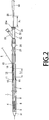
- the catheter apparatus includes a protective sheath 1 and a catheter 2 contained in the sheath 1 with movability to back and forth, as shown in Fig.1 and 2 .
- the catheter 2 constituting this catheter apparatus is a long tubular body with the diameter of one (1) to two (2) mm and the entire length of 70 to 150cm as shown in Figure 3 .
- This catheter 2 is shaped such that it can be deformed in accordance with a curved or tortuous vessel in a living body, such as a blood vessel.
- Conventional types of vascular catheters may be used as the catheter 2.
- the sheath 1 is also made of flexible material which deforms in longitudinal direction. In this embodiment, the sheath 1 is made of polyamide resin.
- a balloon 3 which is inflated by an expansion medium such as a contrast medium is provided as shown in Figure 2 and 3 .
- a stent 4 to be deployed in the desired site in the blood vessel is mounted on the outer periphery of this balloon 3.
- This stent 4 is formed into a cylindrical shape with a channel therein extending from its one end to the other by using, for example, a strand of biodegradable polymer.
- This cylindrically shaped stent 4 is mounted on the outer periphery of the balloon 3 and will be expanded in diameter along with inflation of the balloon 3.
- the proximal side of the stent 4 mounted on the balloon 3 is held by a stent holding member 6.
- the stent holding member 6 is provided so as to prevent the stent 4 from being displaced relative to the balloon 3 during stent expansion, and to ensure reliable expansion of the stent 4 in accordance with the inflation of the balloon 3.
- the catheter 2 is provided with an expansion medium supplying channel 7 through which an expansion medium for expanding the balloon 3 flows.
- the expansion medium supplying channel 7 is formed as a continuous channel which extends from the proximal end of the catheter 2 to the distal end thereof on which the balloon 3 is provided.
- the catheter 2 on which the balloon 3 is attached has a through hole 8 communicated with the expansion medium supplying channel 7. Via the through hole 8, expansion medium supplied to the expansion medium supplying channel 7 flows into the balloon 2 to fill the balloon 3, or the expansion medium filling the balloon 3 is evacuated.
- the section extending from the distal end to the middle portion of the catheter 2 is provided with a guide wire insertion channel 10 into which a guide wire 9 for guiding the catheter 2 is inserted.
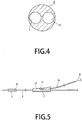
- the section from the distal end of the catheter 2 to the middle portion of the catheter 2 has two channels, the expansion medium supplying channel 7 and the guide wire insertion channel 10, which are paralleled independently.
- the distal open end of the guide wire insertion channel 10 is opened to the distal end of the catheter 2 and its proximal open end opened to the side of the middle portion of the catheter 2.
- the proximal open end is used for a guide wire leading-out opening 11 for leading the guide wire 9 out of the catheter 2.
- the portion of the catheter 2 where the guide wire leading-out opening 11 is provided is formed as a bulge 12 which gradually bulges toward side direction to make a slope.
- the guide wire leading-out opening 11 is formed by cutting the proximal side of the bulge 12 obliquely to the longitudinal line of the catheter 2.
- the cross section of the bulge 12 tilts toward the periphery of the catheter 2 to have large tilt angle to the leading-out direction of the guide wire 9. Consequently, the guide wire 9 can be smoothly led out from the catheter 2.
- the guide wire insertion channel 10 is provided within the range of 10 to 40cm from the distal end of the catheter 2.
- the guide wire leading-out opening 11 is provided within 10 to 40cm from the distal end of the catheter 2.
- a guide wire drawing-out opening 13 is provided in the middle portion of the sheath 1 containing the catheter 2, which is to draw out the guide wire 9 led out from the guide wire leading-out opening 11.
- a guide wire drawing-out guiding mechanism 14 connecting the guide wire leading-out opening 11 and the guide wire drawing-out opening 13 is provided for guiding the guide wire 9 led out from the guide wire leading-out opening 11 to the guide wire drawing-out opening 13.
- the guide wire drawing-out guiding mechanism 14 moves back and forth in accordance with the relative movement of the sheath 1 to the catheter 2, varying the distance between the guide wire leading-out opening 11 and the guide wire drawing-out opening 13.
- the length of this guide wire drawing-out guiding mechanism 14 varies in accordance with changes of the distance between the guide wire leading-out opening 11 and the guide wire drawing-out opening 13 caused by the relative movement between the sheath 1 and the catheter 2. Therefore the guide wire 9 drew out from the catheter 2 toward the sheath 1 can remain linear without warping or bending.
- the guide wire drawing-out guiding mechanism 14 comprises a first tubular member 15, the proximal end of which is connected with the guide wire leading-out opening 11 on the catheter 2, extending along the outer surface of the catheter 2 toward the guide wire drawing-out opening 13 on the sheath 1, and a second tubular member 16, the proximal end of which is connected with the guide wire drawing-out opening 13 on the sheath 1, extending along the inner surface of the sheath 1 toward the guide wire leading-out opening 11 on the catheter 2.
- the first and second tubular members 15 and 16 are a hollow tubular member with an inner diameter sufficient to accommodate the guide wire 9.
- the tubular member 15 and 16 used in this embodiment are preferably formed of a tube made of synthetic resin with smooth and less frictional surface wherein the guide wire 9 formed of a thin metal wire with diameter of 0.3 to 0.6 mm can be smoothly inserted.
- the first and second tubular members 15 and 16 are formed of polyimide synthetic resin.
- the first tubular member 15 is connected with the catheter 2 by fitting its one open end to the guide wire leading-out opening 11 and extends along the outer surface of the catheter 2.
- the proximal end of the first tubular member 15 is clamped to the catheter 2 with a ring-shaped member 17 made of synthetic resin provided on the outer periphery of the catheter 2 to avoid its disengagement from the catheter 2.
- the second tubular member 16 is connected with the sheath 1 by joining the surface of its proximal end to the periphery of the guide wire drawing-out opening 13. The distal end of the second tubular member 16 extends along the inner surface of the sheath 1 toward the guide wire leading-out opening 11.
- the second tubular member 16 is connected with the sheath 1 via a connecting member 19 made of synthetic resin.
- the connecting member 19 is connected with the second tubular member 16 by fitting its one end to the proximal end of the second tubular member 16.
- the joint part of the connecting member 19 with the second tubular member 16 may be further bonded with an adhesive.
- This connecting member 19 is made of synthetic resin having a melting point lower than that of the second tubular member 16.
- the connecting member 19 is connected with the inner surface of the sheath 1 with its proximal end surface 19a joined to the periphery of the guide wire drawing-out opening 13.
- the second tubular member 16 is connected to the sheath 1 by joining the connecting member 19 on its proximal end to the sheath 1.
- the connecting member 19 is thermally welded to be connected to the sheath 1.
- the perimeter of the proximal end surface 19a of the connecting member 19 is joined together with the perimeter of the guide wire drawing-out opening 13 such that the guide wire drawing-out opening 13 is completely covered to prevent leakage of liquid such as saline solution injected into the sheath 1 for complete air removal from the catheter apparatus.
- the connecting member 19 is made of the same sort of synthetic resin as the sheath 1, whose melting point is same as that of the sheath 1.
- the sheath 1 and the connecting member 19 are formed of polyamide resin such that they are welded at almost the same temperature leading to their tight bond.
- thermal effects such as deformation of the second tubular member 16 due to heat during thermal welding to join the connecting member 19 with the sheath 1
- the connecting member 19 is made of synthetic resin having a melting point lower than that of the second tubular member 16.
- the melting point of the connecting member 19 is lower than that of the second tubular member 16, because the second tubular member 16 is formed of polyimide resin and the sheath 1 and connecting member 19 are formed of polyamide resin.
- the proximal ends of the first tubular member 15 connected with the catheter 2 and the second tubular member 16 connected with the sheath 1 are fitted together allowing their back and forth movement.
- the first tubular member 15 for leading the guide wire 9 led out from the catheter 2 to the sheath 1 is fitted into the inner lumen of the second tubular member 16. In this way, no protrusion which would impede advancement of the guide wire 9 is produced on the inner lumen of the catheter 2 and the sheath 1 where the guide wire 9 runs through, thus smooth advancement of the guide wire 9 is available.
- first tubular member 15 and the second tubular member 16 are fitted each other without large interspace between them such that they can move smoothly when they are moved back and forth with respect to each other.
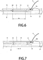
- the first tubular member 15 is, therefore, preferably formed as a tubular member having the outer diameter R 2 which is equal to or slightly smaller than the inner diameter R 1 of the second tubular member 16, as shown in figure 6 .
- an indeflation port 18 communicated to the expansion medium supplying channel 7 is provided at the proximal end of the catheter 2 to be inserted into the sheath 1.
- an indeflator is connected with this indeflation port 18 to supply expansion medium to inflate the baloon3.
- the expansion medium provided from the indeflator enters into the indeflation port 18, runs through the expansion medium supplying channel 7, and flows into the balloon 3 to fill it via the through hole 8 opened at the portion of the catheter 2 where the balloon 3 is provided.
- the stent 4 mounted on the outer periphery of this balloon 3 is expanded in diameter in accordance with the inflation of the balloon 3.
- a connecting member 21 from which the catheter 2 is drawn out is provided at the proximal end of the sheath 1 wherein the catheter 2 attaching the balloon 3 is provided allowing its free back and forth movement.
- This connecting member 21 is provided with a catheter port 22 to draw out the catheter 2 from the sheath 1 and an indeflation port 23 for supplying liquid such as saline solution to remove air in the sheath 1.
- the connecting member 21 is attached to the sheath 1 via a connecting hub 24 attached to the proximal portion of the sheath 1.
- the proximal portion of the catheter port 22 provided in the connecting member 21 includes a clamp fixing mechanism 25 which provides a fixing mean for fixing the relative movement between the sheath 1 and the catheter 2 drawn out from the proximal end of the sheath 1.
- this clamp fixing mechanism 25 the screw body is screwed into/out of the catheter port 22 by turning a screw head 25a, thus clamps the catheter 2 and restrains its relative movement to the sheath 1.
- the first tubular member 15 constituting the guide wire drawing-out guiding mechanism 14 is formed as a tubular member having an overlap length L 2 longer than an exposing length L 1 of the catheter 2 from the sheath 1 at their distal section as shown in figure 8 , when the sheath 1 is pulled back in the direction of arrow P, that is toward the operator's hand, shown in figure 7 with respect to the catheter to inflate the balloon(see also figures 1 and 6 ).
- the connection of the first and second tubular members 15 and 16 can be maintained, even when the sheath 1 is pulled back in the direction of arrow P, that is, toward the operator's body side, with respect to the catheter 2 to uncover the distal portion of the catheter 2 where the balloon is provided. Consequently, even when the distance between the guide wire leading-out opening 11 and the guide wire drawing-out opening 13 is changed according to the pull back of the sheath 1, the connection between the first and second tubular members 15 and 16 is always guaranteed, allowing the guide wire 9 to be surely drawn out toward the side direction of the sheath 1.
- a pullback restriction member 26 is provided at the proximal portion of the catheter 2 drawn out from the proximal portion of the sheath 1 for restricting the pull back distance of the sheath 1 with respect to the catheter 2 to prevent release of the connection between the first and second tubular members 15 and 16.
- This pullback restriction member 26 is formed as a bulge having a diameter larger than the inner diameter of the catheter port 22 provided in the connecting member 21 attached at the proximal end of the sheath 1.
- the pullback distance of the sheath 1 with respect to the catheter 2 is restricted by the abutment of the open end of the catheter drawing-out port 22 with the distal end of the pullback restriction member 26.
- the pullback restriction member 26 is provided where it can restrict the pullback distance of the sheath 1 with respect to the catheter 2 so as not to lose the overlap between the first and second tubular members 15 and 16, when the sheath 1 is pulled back with respect to the catheter 2 in the shown in figure 8 and the second tubular member 16 subsequently moves in the arrow P direction with respect to the first tubular member 1.
- the pullback restriction member 26 is provided so that the migration distance X 1 of the sheath 1 with respect to the catheter 2 in the direction of arrow P shown in figure 8 is shorter than the overlap length L 2 of the first and second tubular members 15 and 16.
- the stent 4 is reliably expanded by releasing from the balloon 3, because the pullback distance of the sheath 1 with respect to the catheter 2 is restricted at the position where it is pulled back by the length to expose the stent 4 mounted on the balloon 3 outwardly,.
- disengagement or dislocation of the stent 4 from the balloon can be surely prevented, because it is reliably mounted in a contracted state on the balloon 3 at the proximal end of the catheter 2.
- connection assist member 27 a stiff tubular member, is connected to the proximal portion of the sheath 1.
- This connection assist member 27 connects a connection hub 24 for the connection of the connecting member 21 with the sheath 1. It is formed of a tubular member made of metal such as stainless steel or aluminum.
- a stopper 31 is provided at the distal end of the catheter 2 to restrict the retracted position with respect to the sheath 1 of the balloon 3 provided at the distal portion of the catheter 2 and the stent 4 mounted on the balloon.
- This stopper 31 is tapered and functioning as a guide to help advancement of the catheter 2 in a vessel such as a blood vessel.
- a catheter apparatus For implantation of the stent 4 into a blood vessel, a catheter apparatus provided with balloon attaching the stent 4 is prepared.
- the stent 4 is radially contracted and mounted on the contracted balloon 3 covered by the sheath 1.
- the catheter 2 As shown in figure 1 , the catheter 2 is contained in the sheath 1 being restricted its relative movement to the sheath 1 by the clamp fixing mechanism 25.
- the proximal end of the guide wire 9 advanced toward a stenosed portion in a blood vessel is inserted into the guide wire insertion channel 10 at the distal end of the catheter 2.
- the guide wire 9 is advanced through the guide wire insertion channel 10, led out from the guide wire leading-out opening 11 provided at the proximal end of the guide wire insertion channel 10 into the first tubular member 15.
- the guide wire advanced in the first tubular member 15 is led to the second tubular member 16 connected with the first tubular member 15 constituting the guide wire drawing-out guiding mechanism 14.
- the guide wire 9 led into the second tubular member 16 is drew out through the guide wire drawing-out opening 13 along the sheath 1.
- the catheter 2 With tightly grasping to secure the end of the guide wire 9 drew out along the sheath 1, the catheter 2 is inserted into the blood vessel with the guidance of the guide wire 9 to deploy the balloon 3 attached on the distal end of the catheter 2 together with the stent mounted on the balloon 3 in the intended site for implantation. The catheter 2 is advanced through the blood vessel together with the sheath 1.
- the second tubular member 16 moves, along with the sheath 1, in the direction of arrow P shown in figure 7 and the second tubular member 16 is pulled from the first tubular member 15.
- the connection between the first and second tubular members 15 and 16 is maintained, even when the sheath 1 is pulled back with respect to the catheter 2 by the length L 1 sufficient for release the support for the balloon 3 at the distal end to expose it from the sheath 1, because the first and second tubular members 15 and 16 are connected with the overlap length L 2 longer than the migration length X 1 sufficient for release the support for the balloon 3 at the distal end to expose it from the sheath. Consequently, the connection between the first and second tubular members 15 and 16 is maintained such that the guide wire 9 is inserted into them to guide the catheter 2.
- the balloon 3 exposed from the distal end of the sheath 1 is inflated, by using the indeflator, with contrast medium supplied through the expansion medium supplying channel 7 in the catheter 2 via the thorough hole 8.
- the stent 4 mounted on the balloon 3 is expanded in diameter.
- the stent 4 thus expanded in diameter comes to be in a state to scaffold the inner wall of the blood vessel from inside.
- the expansion medium filling the balloon 3 is drawn through the expansion medium supplying channel 7 for decompression and contraction.
- the stent 4 previously expanded in diameter keeps the expanded state, is disengaged from the balloon 3 contracted in diameter and is remained at the stenting position in the blood vessel such that the implantation for keeping the state scaffolding the inner wall of the blood vessel is accomplished.
- the catheter apparatus according to the present invention can achieve advantages of monorail catheters, while including the sheath 1 holding the stent 4 mounted on the balloon 3 provided on the catheter 2.
- the catheter apparatus according to the present invention effectively utilizes the advantages of the monorail catheter, surely prevents dislocation or disengagement of the stent 4 mounted on the balloon 3 provided on the catheter 2, as well as quickly implants the stent 4 in a vessel in a living body, such as a blood vessel.
- the vascular stent 4 mounted on the catheter apparatus according to the present invention is not limited to the illustrative stent made of a biodegradable polymer. Any type of stents including metal stents may be broadly used for balloon expandable stents.
- the present invention can be applied to implantations of stents in a vessel of a living body such as an ureter and a bile duct rather than a blood vessel.
Landscapes
- Health & Medical Sciences (AREA)
- Life Sciences & Earth Sciences (AREA)
- Engineering & Computer Science (AREA)
- Biomedical Technology (AREA)
- Veterinary Medicine (AREA)
- Animal Behavior & Ethology (AREA)
- Heart & Thoracic Surgery (AREA)
- Public Health (AREA)
- General Health & Medical Sciences (AREA)
- Oral & Maxillofacial Surgery (AREA)
- Transplantation (AREA)
- Vascular Medicine (AREA)
- Cardiology (AREA)
- Biophysics (AREA)
- Pulmonology (AREA)
- Anesthesiology (AREA)
- Hematology (AREA)
- Media Introduction/Drainage Providing Device (AREA)
Claims (10)
- Medizinische Kathetervorrichtung, umfassend:einen Katheter (2), der einen äußeren Umfang aufweist, auf welchem ein zylindrischer vaskulärer Stent (4) montiert werden soll, und einen Distalteil, der einen Ballon (3) anbringt, welcher unter Zufuhr eines Expansionsmediums aufgebläht werden soll, um den Stent (4) im Durchmesser zu expandieren, versehen mit zumindest einem ein Expansionsmedium zuführenden Kanal (7), der sich vom Distalteil zu einem Proximalteil erstreckt, um das Expansionsmedium zuzuführen, um den Ballon (3) zu expandieren, und einem Führungsdraht-Einführungskanal (10), der sich vom Distalteil zu einem Mittelteil erstreckt, um einen Führungsdraht (9) einzuführen, undeinen Mantel (1), in welchen der Katheter (2) eingeführt ist, welcher den äußeren Umfang des Katheters von dessen Distalseite, wo der den vaskulären Stent (4) anbringende Ballon (3) positioniert ist, bis zu dessen Proximalseite bedeckt und sich in Bezug auf den Katheter (2) zwischen dem Abschnitt, wo er den den vaskulären Stent (4) anbringenden Ballon (3) bedeckt, und dem Abschnitt bewegt, wo er den am Ballon (3) angebrachten vaskulären Stent (4) freilegen soll, wobeider Katheter (2) am Mittelteil mit einer einen Führungsdraht ausleitenden Öffnung (11) versehen ist, um den vom Distalteil des Katheters (2) eingeführten Führungsdraht (9) zur seitlichen Richtung des Katheters (2) auszuleiten,der Mantel (1) an einem Mittelteil mit einer Führungsdraht-Ausziehöffnung (13) versehen ist, um den aus dem Katheter (2) gezogenen Führungsdraht (9) aus dem Mantel (1) herauszuziehen,ein Führungsmechanismus (14) zum Herausziehen des Führungsdrahtes zwischen der einen Führungsdraht ausleitenden Öffnung (11) und der Führungsdraht-Ausziehöffnung (13) vorgesehen ist, um die einen Führungsdraht ausleitende Öffnung (11) und die Führungsdraht-Ausziehöffnung (13) zu verbinden und um den aus der einen Führungsdraht ausleitenden Öffnung (11) ausgeleiteten Führungsdraht (9) zur Führungsdraht-Ausziehöffnung (13) zu führen, undder Führungsmechanismus (14) zum Herausziehen des Führungsdrahtes eine variable Länge von der einen Führungsdraht ausleitenden Öffnung (11) zur Führungsdraht-Ausziehöffnung (13) aufweist und dafür eingerichtet ist, die Länge mit der relativen Bewegung des Mantels (1) in Bezug auf den Katheter (2) zu variieren.
- Medizinische Kathetervorrichtung nach Anspruch 1, wobei der Führungsmechanismus (14) zum Herausziehen des Führungsdrahtes umfasst
ein erstes röhrenförmiges Element (15), dessen Proximalende mit der auf dem Katheter (2) ausgebildeten, einen Führungsdraht ausleitenden Öffnung (11) verbunden ist, verlaufend entlang der äußeren Oberfläche des Katheters (2) in Richtung der auf dem Mantel (1) ausgebildeten Führungsdraht-Ausziehöffnung (13), und
ein zweites röhrenförmiges Element (16), dessen Proximalende mit der auf dem Mantel (1) ausgebildeten Führungsdraht-Ausziehöffnung (13) verbunden ist, verlaufend entlang der inneren Oberfläche des Mantels (1) in Richtung der auf dem Katheter (2) ausgebildeten, einen Führungsdraht ausleitenden Öffnung (11),
wobei das erste röhrenförmige Element (15) und das zweite röhrenförmige Element (16) hin und her bewegbar verbunden sind, indem ihre Endabschnitte verschiebbar montiert sind. - Medizinische Kathetervorrichtung nach Anspruch 2, wobei das erste röhrenförmige Element (15) von einem röhrenförmigen Element (15) mit einem Außendurchmesser gebildet wird, der kleiner oder gleich einem Innendurchmesser des zweiten röhrenförmigen Elements (16) ist, wobei das Ende des ersten röhrenförmigen Elements (15) so in das zweite röhrenförmige Element (16) eingesetzt ist, dass das erste röhrenförmige Element (15) hin und her bewegbar mit dem zweiten röhrenförmigen Element (16) verbunden ist.
- Medizinische Kathetervorrichtung nach Anspruch 2, ferner umfassend ein röhrenförmiges Verbindungselement (19), das mit dem Proximalteil des zweiten röhrenförmigen Elements (16) verbunden ist, um mit dem Mantel (1) verbunden zu werden, wobei das zweite röhrenförmige Element (16) mit der inneren Oberfläche des Mantels (1) verbunden ist, indem eine proximale Endfläche des Verbindungselements (19) mit dem Umfang der Führungsdraht-Ausziehöffnung (13) verbunden ist und die Führungsdraht-Ausziehöffnung (13) abdichtet.
- Medizinische Kathetervorrichtung nach Anspruch 4, wobei zumindest der Mantel (1) und das zweite röhrenförmige Element (16) aus einem synthetischen Harzmaterial bestehen und das das zweite röhrenförmige Element (16) mit dem Mantel (1) verbindende Verbindungselement (19) aus einem synthetischen Harzmaterial besteht, das einen niedrigeren Schmelzpunkt als denjenigen des zweiten röhrenförmigen Elements (16) aufweist.
- Medizinische Kathetervorrichtung nach Anspruch 2, wobei das erste röhrenförmige Element (15), das den Führungsmechanismus (14) zum Herausziehen des Führungsdrahtes bildet, als ein röhrenförmiges Element (15) mit einer Länge ausgebildet ist, die in das zweite röhrenförmige Element (16) mit einer Überlappungslänge L2 eingesetzt wird, welche länger als eine Migrationslänge L1 ist, um welche der am Distalteil des Katheters (2) vorgesehene Ballon (3) vom Distalteil des Mantels (1) zu einer Position wandert, welche den Ballon (3) nach außen freilegt, wenn der Mantel (1) in Bezug auf den Katheter (2) gezogen wird.
- Medizinische Kathetervorrichtung nach Anspruch 6, ferner umfassend ein Beschränkungselement (26), das am Proximalteil des aus dem Proximalteil des Mantels (1) herausgezogenen Katheters vorgesehen ist, um einen Umfang der Bewegung des Mantels (1) in Bezug auf den Katheter (2) zu beschränken, um eine Länge zu beschränken, um welche der Distalteil des Katheters (2), der mit dem Ballon versehen wurde, aus dem Distalende des Mantels (1) freigelegt wird.
- Medizinische Kathetervorrichtung nach Anspruch 6, ferner umfassend ein Verbindungselement (27), das mit dem Proximalteil des Mantels verbunden ist und einen Katheter-Ausziehanschluss aufweist, wobei der Katheter (2) durch den Katheter-Ausziehanschluss aus dem Mantel (1) herausgezogen wird, und ferner umfassend ein Beschränkungselement (31), das am Distalteil des durch den Katheter-Ausziehanschluss herausgezogenen Katheters (2) vorgesehen ist, um einen Umfang der Bewegung des Mantels (1) in Bezug auf den Katheter (2) zu beschränken, wobei das Beschränkungselement (31) einen Durchmesser aufweist, der größer als der Innendurchmesser des Katheter-Ausziehanschlusses ist, um eine Länge zu beschränken, um welche der Distalteil des Katheters (2), der mit dem Ballon (3) versehen wurde, aus dem Distalende des Mantels (1) freigelegt wird.
- Medizinische Kathetervorrichtung nach Anspruch 1, wobei die Führungsdraht-Ausziehöffnung (13) vom Distalende des Mantels (1) um 15 cm bis 45 cm jeweils inklusiv entfernt gelegen ist.
- Medizinische Kathetervorrichtung nach Anspruch 1, wobei der vaskuläre Stent (4), der auf dem am Distalteil des Katheters (2) vorgesehenen Ballon (3) montiert ist, in kontrahiertem Zustand montiert ist.
Applications Claiming Priority (2)
| Application Number | Priority Date | Filing Date | Title |
|---|---|---|---|
| JP2009221435 | 2009-09-25 | ||
| PCT/JP2010/005519 WO2011036852A1 (ja) | 2009-09-25 | 2010-09-09 | 医療用のカテーテル装置 |
Publications (3)
| Publication Number | Publication Date |
|---|---|
| EP2481379A1 EP2481379A1 (de) | 2012-08-01 |
| EP2481379A4 EP2481379A4 (de) | 2015-11-25 |
| EP2481379B1 true EP2481379B1 (de) | 2017-03-01 |
Family
ID=43795622
Family Applications (1)
| Application Number | Title | Priority Date | Filing Date |
|---|---|---|---|
| EP10818533.1A Not-in-force EP2481379B1 (de) | 2009-09-25 | 2010-09-09 | Medizinische kathetervorrichtung |
Country Status (5)
| Country | Link |
|---|---|
| US (1) | US8617232B2 (de) |
| EP (1) | EP2481379B1 (de) |
| JP (1) | JP4798675B2 (de) |
| KR (1) | KR20120081066A (de) |
| WO (1) | WO2011036852A1 (de) |
Families Citing this family (25)
| Publication number | Priority date | Publication date | Assignee | Title |
|---|---|---|---|---|
| DE102005003632A1 (de) | 2005-01-20 | 2006-08-17 | Fraunhofer-Gesellschaft zur Förderung der angewandten Forschung e.V. | Katheter für die transvaskuläre Implantation von Herzklappenprothesen |
| US7896915B2 (en) | 2007-04-13 | 2011-03-01 | Jenavalve Technology, Inc. | Medical device for treating a heart valve insufficiency |
| US9044318B2 (en) | 2008-02-26 | 2015-06-02 | Jenavalve Technology Gmbh | Stent for the positioning and anchoring of a valvular prosthesis |
| WO2011104269A1 (en) | 2008-02-26 | 2011-09-01 | Jenavalve Technology Inc. | Stent for the positioning and anchoring of a valvular prosthesis in an implantation site in the heart of a patient |
| US10856978B2 (en) | 2010-05-20 | 2020-12-08 | Jenavalve Technology, Inc. | Catheter system |
| US11278406B2 (en) | 2010-05-20 | 2022-03-22 | Jenavalve Technology, Inc. | Catheter system for introducing an expandable heart valve stent into the body of a patient, insertion system with a catheter system and medical device for treatment of a heart valve defect |
| WO2011147849A1 (en) | 2010-05-25 | 2011-12-01 | Jenavalve Technology Inc. | Prosthetic heart valve and transcatheter delivered endoprosthesis comprising a prosthetic heart valve and a stent |
| AU2011335994A1 (en) * | 2010-11-29 | 2013-06-06 | Kyoto Medical Planning Co., Ltd. | Medical catheter device |
| JP5885057B2 (ja) * | 2011-09-02 | 2016-03-15 | ニプロ株式会社 | ステントデリバリーカテーテル |
| WO2015028209A1 (en) | 2013-08-30 | 2015-03-05 | Jenavalve Technology Gmbh | Radially collapsible frame for a prosthetic valve and method for manufacturing such a frame |
| KR101602558B1 (ko) * | 2014-04-08 | 2016-03-10 | 주식회사 파인메딕스 | 내시경적 역행성 담도 췌장 조영술용 유두 절개도 |
| KR101663754B1 (ko) | 2014-06-02 | 2016-10-10 | 이상협 | 보형물 삽입기구 |
| EP3270825B1 (de) | 2015-03-20 | 2020-04-22 | JenaValve Technology, Inc. | Herzklappenprothesenzuführsystem |
| WO2016164682A1 (en) | 2015-04-09 | 2016-10-13 | Boston Scientific Scimed, Inc. | Trap balloon catheter with trap balloon retainer |
| EP3288495B1 (de) | 2015-05-01 | 2019-09-25 | JenaValve Technology, Inc. | Vorrichtung mit reduzierter herzschrittmacherrate bei herzklappenersatz |
| CN108136156B (zh) * | 2015-05-29 | 2020-12-29 | 生物传感器国际集团有限公司 | 双内腔管式导管支承系统 |
| JP6426068B2 (ja) * | 2015-08-10 | 2018-11-21 | 朝日インテック株式会社 | カテーテル及びバルーンカテーテル |
| WO2017195125A1 (en) | 2016-05-13 | 2017-11-16 | Jenavalve Technology, Inc. | Heart valve prosthesis delivery system and method for delivery of heart valve prosthesis with introducer sheath and loading system |
| US11197754B2 (en) | 2017-01-27 | 2021-12-14 | Jenavalve Technology, Inc. | Heart valve mimicry |
| KR102053207B1 (ko) * | 2018-03-07 | 2020-01-08 | 인제대학교 산학협력단 | 길이조절이 가능한 카테타 어셈블리 |
| CN112714659B (zh) * | 2018-08-24 | 2023-01-06 | 株式会社钟化 | 医疗用管状体运送装置 |
| US20220054286A1 (en) * | 2019-11-06 | 2022-02-24 | Mg Stroke Analytics Inc. | Stent and Catheter Systems for Treatment of Unstable Plaque and Cerebral Aneurysm |
| CN114515376B (zh) * | 2022-02-17 | 2024-01-26 | 湖南朗开医疗科技有限公司 | 一种用于引导导丝的穿透型定位导管 |
| EP4496615A4 (de) * | 2022-03-22 | 2026-03-25 | Univ Rutgers | Neuroaspirationskatheter für thrombektomie |
| US12171658B2 (en) | 2022-11-09 | 2024-12-24 | Jenavalve Technology, Inc. | Catheter system for sequential deployment of an expandable implant |
Family Cites Families (8)
| Publication number | Priority date | Publication date | Assignee | Title |
|---|---|---|---|---|
| US5389087A (en) | 1991-09-19 | 1995-02-14 | Baxter International Inc. | Fully exchangeable over-the-wire catheter with rip seam and gated side port |
| JPH08500757A (ja) * | 1992-12-30 | 1996-01-30 | シュナイダー・(ユーエスエイ)・インコーポレーテッド | 身体に移植可能なステントを展開する装置 |
| JP4584832B2 (ja) | 2003-05-23 | 2010-11-24 | 株式会社 京都医療設計 | ステント供給装置 |
| US7323006B2 (en) * | 2004-03-30 | 2008-01-29 | Xtent, Inc. | Rapid exchange interventional devices and methods |
| US20060036233A1 (en) | 2004-08-12 | 2006-02-16 | Scimed Life Systems, Inc. | Catheter incorporating a guidewire exit ramp |
| EP3266414B1 (de) * | 2005-05-12 | 2024-07-17 | Covidien LP | Implantatfreisetzungssystem mit verzahnter rx-port-ausrichtung |
| JP2008104660A (ja) | 2006-10-25 | 2008-05-08 | Kaneka Corp | 医療用バルーンカテーテル |
| ES2550752T3 (es) * | 2007-04-09 | 2015-11-12 | Covidien Lp | Stent extensible y sistema de envío |
-
2010
- 2010-09-09 EP EP10818533.1A patent/EP2481379B1/de not_active Not-in-force
- 2010-09-09 JP JP2011516601A patent/JP4798675B2/ja not_active Expired - Fee Related
- 2010-09-09 KR KR20127001773A patent/KR20120081066A/ko not_active Withdrawn
- 2010-09-09 WO PCT/JP2010/005519 patent/WO2011036852A1/ja not_active Ceased
- 2010-09-09 US US13/497,010 patent/US8617232B2/en not_active Expired - Fee Related
Non-Patent Citations (1)
| Title |
|---|
| None * |
Also Published As
| Publication number | Publication date |
|---|---|
| EP2481379A4 (de) | 2015-11-25 |
| WO2011036852A1 (ja) | 2011-03-31 |
| JPWO2011036852A1 (ja) | 2013-02-14 |
| EP2481379A1 (de) | 2012-08-01 |
| JP4798675B2 (ja) | 2011-10-19 |
| US8617232B2 (en) | 2013-12-31 |
| US20120185030A1 (en) | 2012-07-19 |
| KR20120081066A (ko) | 2012-07-18 |
Similar Documents
| Publication | Publication Date | Title |
|---|---|---|
| EP2481379B1 (de) | Medizinische kathetervorrichtung | |
| US10610390B2 (en) | Implant delivery system and method of use | |
| ES2429220T3 (es) | Aparato para tratar una válvula cardiaca defectuosa | |
| EP2647357A1 (de) | Medizinische kathetervorrichtung | |
| EP1796583B1 (de) | Vorrichtung zur abgabe einer endovaskulären stentprothese mit einem in längsrichtung ungestützten teil | |
| JP4721276B2 (ja) | 脈管用ステント供給装置 | |
| JP6321256B2 (ja) | 予めカニューレが挿入された開窓部 | |
| EP2893907B1 (de) | Einführvorrichtung für eine einführbare medizinische Vorrichtung | |
| EP2306939B1 (de) | Einführkatheter mit gebogener distaler spitze | |
| US20050267563A1 (en) | Exchangeable delivery system for expandable prosthetic devices | |
| US9220618B2 (en) | Medical catheter device | |
| US20060247757A1 (en) | Delivery system comprising a self expanding stent | |
| EP3315101A1 (de) | Begrenzung einer vorgespannten abzweigdrahtschleife | |
| JP2017063828A (ja) | ステントデリバリーシステム、およびカテーテル組立体 | |
| HK1152224B (en) | Device delivery catheter having a curved distal tip | |
| MXPA06005017A (en) | Treatment of vascular bifurcations |
Legal Events
| Date | Code | Title | Description |
|---|---|---|---|
| PUAI | Public reference made under article 153(3) epc to a published international application that has entered the european phase |
Free format text: ORIGINAL CODE: 0009012 |
|
| 17P | Request for examination filed |
Effective date: 20120320 |
|
| AK | Designated contracting states |
Kind code of ref document: A1 Designated state(s): AL AT BE BG CH CY CZ DE DK EE ES FI FR GB GR HR HU IE IS IT LI LT LU LV MC MK MT NL NO PL PT RO SE SI SK SM TR |
|
| DAX | Request for extension of the european patent (deleted) | ||
| RA4 | Supplementary search report drawn up and despatched (corrected) |
Effective date: 20151022 |
|
| RIC1 | Information provided on ipc code assigned before grant |
Ipc: A61M 25/00 20060101AFI20151016BHEP Ipc: A61M 25/01 20060101ALI20151016BHEP Ipc: A61F 2/958 20130101ALI20151016BHEP Ipc: A61M 25/06 20060101ALI20151016BHEP |
|
| REG | Reference to a national code |
Ref country code: DE Ref legal event code: R079 Ref document number: 602010040462 Country of ref document: DE Free format text: PREVIOUS MAIN CLASS: A61F0002840000 Ipc: A61M0025000000 |
|
| GRAP | Despatch of communication of intention to grant a patent |
Free format text: ORIGINAL CODE: EPIDOSNIGR1 |
|
| RIC1 | Information provided on ipc code assigned before grant |
Ipc: A61M 25/06 20060101ALI20160829BHEP Ipc: A61M 25/00 20060101AFI20160829BHEP Ipc: A61M 25/01 20060101ALI20160829BHEP Ipc: A61F 2/958 20130101ALI20160829BHEP |
|
| INTG | Intention to grant announced |
Effective date: 20160923 |
|
| STAA | Information on the status of an ep patent application or granted ep patent |
Free format text: STATUS: GRANT OF PATENT IS INTENDED |
|
| GRAS | Grant fee paid |
Free format text: ORIGINAL CODE: EPIDOSNIGR3 |
|
| GRAA | (expected) grant |
Free format text: ORIGINAL CODE: 0009210 |
|
| STAA | Information on the status of an ep patent application or granted ep patent |
Free format text: STATUS: THE PATENT HAS BEEN GRANTED |
|
| AK | Designated contracting states |
Kind code of ref document: B1 Designated state(s): AL AT BE BG CH CY CZ DE DK EE ES FI FR GB GR HR HU IE IS IT LI LT LU LV MC MK MT NL NO PL PT RO SE SI SK SM TR |
|
| REG | Reference to a national code |
Ref country code: GB Ref legal event code: FG4D |
|
| REG | Reference to a national code |
Ref country code: CH Ref legal event code: EP Ref country code: AT Ref legal event code: REF Ref document number: 870559 Country of ref document: AT Kind code of ref document: T Effective date: 20170315 |
|
| REG | Reference to a national code |
Ref country code: IE Ref legal event code: FG4D |
|
| REG | Reference to a national code |
Ref country code: DE Ref legal event code: R096 Ref document number: 602010040462 Country of ref document: DE |
|
| REG | Reference to a national code |
Ref country code: NL Ref legal event code: MP Effective date: 20170301 |
|
| REG | Reference to a national code |
Ref country code: LT Ref legal event code: MG4D |
|
| REG | Reference to a national code |
Ref country code: AT Ref legal event code: MK05 Ref document number: 870559 Country of ref document: AT Kind code of ref document: T Effective date: 20170301 |
|
| PG25 | Lapsed in a contracting state [announced via postgrant information from national office to epo] |
Ref country code: FI Free format text: LAPSE BECAUSE OF FAILURE TO SUBMIT A TRANSLATION OF THE DESCRIPTION OR TO PAY THE FEE WITHIN THE PRESCRIBED TIME-LIMIT Effective date: 20170301 Ref country code: NO Free format text: LAPSE BECAUSE OF FAILURE TO SUBMIT A TRANSLATION OF THE DESCRIPTION OR TO PAY THE FEE WITHIN THE PRESCRIBED TIME-LIMIT Effective date: 20170601 Ref country code: GR Free format text: LAPSE BECAUSE OF FAILURE TO SUBMIT A TRANSLATION OF THE DESCRIPTION OR TO PAY THE FEE WITHIN THE PRESCRIBED TIME-LIMIT Effective date: 20170602 Ref country code: HR Free format text: LAPSE BECAUSE OF FAILURE TO SUBMIT A TRANSLATION OF THE DESCRIPTION OR TO PAY THE FEE WITHIN THE PRESCRIBED TIME-LIMIT Effective date: 20170301 Ref country code: LT Free format text: LAPSE BECAUSE OF FAILURE TO SUBMIT A TRANSLATION OF THE DESCRIPTION OR TO PAY THE FEE WITHIN THE PRESCRIBED TIME-LIMIT Effective date: 20170301 |
|
| PG25 | Lapsed in a contracting state [announced via postgrant information from national office to epo] |
Ref country code: SE Free format text: LAPSE BECAUSE OF FAILURE TO SUBMIT A TRANSLATION OF THE DESCRIPTION OR TO PAY THE FEE WITHIN THE PRESCRIBED TIME-LIMIT Effective date: 20170301 Ref country code: ES Free format text: LAPSE BECAUSE OF FAILURE TO SUBMIT A TRANSLATION OF THE DESCRIPTION OR TO PAY THE FEE WITHIN THE PRESCRIBED TIME-LIMIT Effective date: 20170301 Ref country code: BG Free format text: LAPSE BECAUSE OF FAILURE TO SUBMIT A TRANSLATION OF THE DESCRIPTION OR TO PAY THE FEE WITHIN THE PRESCRIBED TIME-LIMIT Effective date: 20170601 Ref country code: AT Free format text: LAPSE BECAUSE OF FAILURE TO SUBMIT A TRANSLATION OF THE DESCRIPTION OR TO PAY THE FEE WITHIN THE PRESCRIBED TIME-LIMIT Effective date: 20170301 Ref country code: LV Free format text: LAPSE BECAUSE OF FAILURE TO SUBMIT A TRANSLATION OF THE DESCRIPTION OR TO PAY THE FEE WITHIN THE PRESCRIBED TIME-LIMIT Effective date: 20170301 |
|
| REG | Reference to a national code |
Ref country code: FR Ref legal event code: PLFP Year of fee payment: 8 |
|
| PG25 | Lapsed in a contracting state [announced via postgrant information from national office to epo] |
Ref country code: NL Free format text: LAPSE BECAUSE OF FAILURE TO SUBMIT A TRANSLATION OF THE DESCRIPTION OR TO PAY THE FEE WITHIN THE PRESCRIBED TIME-LIMIT Effective date: 20170301 |
|
| PG25 | Lapsed in a contracting state [announced via postgrant information from national office to epo] |
Ref country code: RO Free format text: LAPSE BECAUSE OF FAILURE TO SUBMIT A TRANSLATION OF THE DESCRIPTION OR TO PAY THE FEE WITHIN THE PRESCRIBED TIME-LIMIT Effective date: 20170301 Ref country code: SK Free format text: LAPSE BECAUSE OF FAILURE TO SUBMIT A TRANSLATION OF THE DESCRIPTION OR TO PAY THE FEE WITHIN THE PRESCRIBED TIME-LIMIT Effective date: 20170301 Ref country code: EE Free format text: LAPSE BECAUSE OF FAILURE TO SUBMIT A TRANSLATION OF THE DESCRIPTION OR TO PAY THE FEE WITHIN THE PRESCRIBED TIME-LIMIT Effective date: 20170301 Ref country code: CZ Free format text: LAPSE BECAUSE OF FAILURE TO SUBMIT A TRANSLATION OF THE DESCRIPTION OR TO PAY THE FEE WITHIN THE PRESCRIBED TIME-LIMIT Effective date: 20170301 Ref country code: IT Free format text: LAPSE BECAUSE OF FAILURE TO SUBMIT A TRANSLATION OF THE DESCRIPTION OR TO PAY THE FEE WITHIN THE PRESCRIBED TIME-LIMIT Effective date: 20170301 |
|
| PG25 | Lapsed in a contracting state [announced via postgrant information from national office to epo] |
Ref country code: PT Free format text: LAPSE BECAUSE OF FAILURE TO SUBMIT A TRANSLATION OF THE DESCRIPTION OR TO PAY THE FEE WITHIN THE PRESCRIBED TIME-LIMIT Effective date: 20170703 Ref country code: PL Free format text: LAPSE BECAUSE OF FAILURE TO SUBMIT A TRANSLATION OF THE DESCRIPTION OR TO PAY THE FEE WITHIN THE PRESCRIBED TIME-LIMIT Effective date: 20170301 Ref country code: SM Free format text: LAPSE BECAUSE OF FAILURE TO SUBMIT A TRANSLATION OF THE DESCRIPTION OR TO PAY THE FEE WITHIN THE PRESCRIBED TIME-LIMIT Effective date: 20170301 Ref country code: IS Free format text: LAPSE BECAUSE OF FAILURE TO SUBMIT A TRANSLATION OF THE DESCRIPTION OR TO PAY THE FEE WITHIN THE PRESCRIBED TIME-LIMIT Effective date: 20170701 |
|
| REG | Reference to a national code |
Ref country code: DE Ref legal event code: R097 Ref document number: 602010040462 Country of ref document: DE |
|
| PLBE | No opposition filed within time limit |
Free format text: ORIGINAL CODE: 0009261 |
|
| STAA | Information on the status of an ep patent application or granted ep patent |
Free format text: STATUS: NO OPPOSITION FILED WITHIN TIME LIMIT |
|
| PG25 | Lapsed in a contracting state [announced via postgrant information from national office to epo] |
Ref country code: DK Free format text: LAPSE BECAUSE OF FAILURE TO SUBMIT A TRANSLATION OF THE DESCRIPTION OR TO PAY THE FEE WITHIN THE PRESCRIBED TIME-LIMIT Effective date: 20170301 |
|
| 26N | No opposition filed |
Effective date: 20171204 |
|
| PG25 | Lapsed in a contracting state [announced via postgrant information from national office to epo] |
Ref country code: SI Free format text: LAPSE BECAUSE OF FAILURE TO SUBMIT A TRANSLATION OF THE DESCRIPTION OR TO PAY THE FEE WITHIN THE PRESCRIBED TIME-LIMIT Effective date: 20170301 |
|
| REG | Reference to a national code |
Ref country code: CH Ref legal event code: PL |
|
| GBPC | Gb: european patent ceased through non-payment of renewal fee |
Effective date: 20170909 |
|
| PG25 | Lapsed in a contracting state [announced via postgrant information from national office to epo] |
Ref country code: MC Free format text: LAPSE BECAUSE OF FAILURE TO SUBMIT A TRANSLATION OF THE DESCRIPTION OR TO PAY THE FEE WITHIN THE PRESCRIBED TIME-LIMIT Effective date: 20170301 |
|
| REG | Reference to a national code |
Ref country code: IE Ref legal event code: MM4A |
|
| REG | Reference to a national code |
Ref country code: BE Ref legal event code: MM Effective date: 20170930 |
|
| PG25 | Lapsed in a contracting state [announced via postgrant information from national office to epo] |
Ref country code: LU Free format text: LAPSE BECAUSE OF NON-PAYMENT OF DUE FEES Effective date: 20170909 |
|
| PG25 | Lapsed in a contracting state [announced via postgrant information from national office to epo] |
Ref country code: CH Free format text: LAPSE BECAUSE OF NON-PAYMENT OF DUE FEES Effective date: 20170930 Ref country code: GB Free format text: LAPSE BECAUSE OF NON-PAYMENT OF DUE FEES Effective date: 20170909 Ref country code: LI Free format text: LAPSE BECAUSE OF NON-PAYMENT OF DUE FEES Effective date: 20170930 Ref country code: IE Free format text: LAPSE BECAUSE OF NON-PAYMENT OF DUE FEES Effective date: 20170909 |
|
| PG25 | Lapsed in a contracting state [announced via postgrant information from national office to epo] |
Ref country code: BE Free format text: LAPSE BECAUSE OF NON-PAYMENT OF DUE FEES Effective date: 20170930 |
|
| REG | Reference to a national code |
Ref country code: FR Ref legal event code: PLFP Year of fee payment: 9 |
|
| PG25 | Lapsed in a contracting state [announced via postgrant information from national office to epo] |
Ref country code: MT Free format text: LAPSE BECAUSE OF NON-PAYMENT OF DUE FEES Effective date: 20170909 |
|
| PGFP | Annual fee paid to national office [announced via postgrant information from national office to epo] |
Ref country code: FR Payment date: 20180921 Year of fee payment: 9 |
|
| PGFP | Annual fee paid to national office [announced via postgrant information from national office to epo] |
Ref country code: DE Payment date: 20180926 Year of fee payment: 9 |
|
| PG25 | Lapsed in a contracting state [announced via postgrant information from national office to epo] |
Ref country code: HU Free format text: LAPSE BECAUSE OF FAILURE TO SUBMIT A TRANSLATION OF THE DESCRIPTION OR TO PAY THE FEE WITHIN THE PRESCRIBED TIME-LIMIT; INVALID AB INITIO Effective date: 20100909 |
|
| PG25 | Lapsed in a contracting state [announced via postgrant information from national office to epo] |
Ref country code: CY Free format text: LAPSE BECAUSE OF NON-PAYMENT OF DUE FEES Effective date: 20170301 |
|
| PG25 | Lapsed in a contracting state [announced via postgrant information from national office to epo] |
Ref country code: MK Free format text: LAPSE BECAUSE OF FAILURE TO SUBMIT A TRANSLATION OF THE DESCRIPTION OR TO PAY THE FEE WITHIN THE PRESCRIBED TIME-LIMIT Effective date: 20170301 |
|
| PG25 | Lapsed in a contracting state [announced via postgrant information from national office to epo] |
Ref country code: TR Free format text: LAPSE BECAUSE OF FAILURE TO SUBMIT A TRANSLATION OF THE DESCRIPTION OR TO PAY THE FEE WITHIN THE PRESCRIBED TIME-LIMIT Effective date: 20170301 |
|
| REG | Reference to a national code |
Ref country code: DE Ref legal event code: R119 Ref document number: 602010040462 Country of ref document: DE |
|
| PG25 | Lapsed in a contracting state [announced via postgrant information from national office to epo] |
Ref country code: AL Free format text: LAPSE BECAUSE OF FAILURE TO SUBMIT A TRANSLATION OF THE DESCRIPTION OR TO PAY THE FEE WITHIN THE PRESCRIBED TIME-LIMIT Effective date: 20170301 Ref country code: DE Free format text: LAPSE BECAUSE OF NON-PAYMENT OF DUE FEES Effective date: 20200401 |
|
| PG25 | Lapsed in a contracting state [announced via postgrant information from national office to epo] |
Ref country code: FR Free format text: LAPSE BECAUSE OF NON-PAYMENT OF DUE FEES Effective date: 20190930 |