EP2481918A1 - Procédé de fonctionnement d'une éolienne dans un lieu d'effet du RADAR - Google Patents
Procédé de fonctionnement d'une éolienne dans un lieu d'effet du RADAR Download PDFInfo
- Publication number
- EP2481918A1 EP2481918A1 EP20110152546 EP11152546A EP2481918A1 EP 2481918 A1 EP2481918 A1 EP 2481918A1 EP 20110152546 EP20110152546 EP 20110152546 EP 11152546 A EP11152546 A EP 11152546A EP 2481918 A1 EP2481918 A1 EP 2481918A1
- Authority
- EP
- European Patent Office
- Prior art keywords
- rotor
- axis
- radar system
- determining
- value
- Prior art date
- Legal status (The legal status is an assumption and is not a legal conclusion. Google has not performed a legal analysis and makes no representation as to the accuracy of the status listed.)
- Granted
Links
Images

Classifications
-
- F—MECHANICAL ENGINEERING; LIGHTING; HEATING; WEAPONS; BLASTING
- F03—MACHINES OR ENGINES FOR LIQUIDS; WIND, SPRING, OR WEIGHT MOTORS; PRODUCING MECHANICAL POWER OR A REACTIVE PROPULSIVE THRUST, NOT OTHERWISE PROVIDED FOR
- F03D—WIND MOTORS
- F03D7/00—Controlling wind motors
- F03D7/02—Controlling wind motors the wind motors having rotation axis substantially parallel to the air flow entering the rotor
- F03D7/0204—Controlling wind motors the wind motors having rotation axis substantially parallel to the air flow entering the rotor for orientation in relation to wind direction
-
- F—MECHANICAL ENGINEERING; LIGHTING; HEATING; WEAPONS; BLASTING
- F05—INDEXING SCHEMES RELATING TO ENGINES OR PUMPS IN VARIOUS SUBCLASSES OF CLASSES F01-F04
- F05B—INDEXING SCHEME RELATING TO WIND, SPRING, WEIGHT, INERTIA OR LIKE MOTORS, TO MACHINES OR ENGINES FOR LIQUIDS COVERED BY SUBCLASSES F03B, F03D AND F03G
- F05B2260/00—Function
- F05B2260/99—Radar absorption
-
- Y—GENERAL TAGGING OF NEW TECHNOLOGICAL DEVELOPMENTS; GENERAL TAGGING OF CROSS-SECTIONAL TECHNOLOGIES SPANNING OVER SEVERAL SECTIONS OF THE IPC; TECHNICAL SUBJECTS COVERED BY FORMER USPC CROSS-REFERENCE ART COLLECTIONS [XRACs] AND DIGESTS
- Y02—TECHNOLOGIES OR APPLICATIONS FOR MITIGATION OR ADAPTATION AGAINST CLIMATE CHANGE
- Y02E—REDUCTION OF GREENHOUSE GAS [GHG] EMISSIONS, RELATED TO ENERGY GENERATION, TRANSMISSION OR DISTRIBUTION
- Y02E10/00—Energy generation through renewable energy sources
- Y02E10/70—Wind energy
- Y02E10/72—Wind turbines with rotation axis in wind direction
-
- Y—GENERAL TAGGING OF NEW TECHNOLOGICAL DEVELOPMENTS; GENERAL TAGGING OF CROSS-SECTIONAL TECHNOLOGIES SPANNING OVER SEVERAL SECTIONS OF THE IPC; TECHNICAL SUBJECTS COVERED BY FORMER USPC CROSS-REFERENCE ART COLLECTIONS [XRACs] AND DIGESTS
- Y10—TECHNICAL SUBJECTS COVERED BY FORMER USPC
- Y10T—TECHNICAL SUBJECTS COVERED BY FORMER US CLASSIFICATION
- Y10T29/00—Metal working
- Y10T29/49—Method of mechanical manufacture
- Y10T29/49316—Impeller making
Definitions
- the invention relates to a method for operating a wind turbine and an arrangement with such a wind turbine, which is configured to carry out the method.
- the invention further relates to a system with such an arrangement and a radar system, in particular a weather radar system or an air traffic control radar system.
- Weather radar systems are used to detect precipitation, intensity and movement of precipitation systems, to determine the type of precipitation (for example rain, snow, hail), as well as to predict the temporal and spatial evolution of precipitation systems.
- Air traffic control radar systems are used to monitor air traffic.
- Radar systems emit directional primary signals of pulsed electromagnetic radiation in the S-band or L-band of the microwave range.
- the primary signals are generated by means of a pulse magnetron or a klystron tube, which is connected via a waveguide to a parabolic antenna, which is provided both as a transmitting and as a receiving device.
- the electromagnetic pulses radiate out from the radar station radially at a solid angle ⁇ and become in themselves at that solid angle Reflected objects such as rainfall systems, terrain surveys, aircraft, or other anthropogenic objects. Between the individual pulses, the radar station serves as a receiver for reflected secondary signals.
- the horizontal distance of a reflecting object can be determined from the transit time of the reflected electromagnetic wave propagating at the speed of light in the pulse volume.
- the speed of reflecting objects can be derived from (successive) pulses ((pulse) Doppler radar).
- the radial Doppler velocity of the scatterer results from the correlation of the intensities of successively detected secondary pulses.
- the tangential velocity of the spreader with respect to the radar station can be derived from the radial projection of the tangential velocity from scattered signals detected in adjacent angular ranges.
- Wind turbines can have a detrimental effect on the evaluation accuracy of radar systems. Due to the rotational movement of the rotor blades and the wind-dependent changing profile wind turbines generate stray signals that can be misinterpreted by radar systems. If wind turbines are aligned according to a wind direction, which is rotated by approximately 90 ° with respect to the direction of incidence of a radar pulse, the scattering of the moving rotor blades can cause doublets of Speed signatures emerge that resemble natural weather conditions and critical ones Weather conditions can lead to misinterpretations and inaccurate short-term weather forecasts. Likewise, such spurious signals adversely affect the detection of Aircraft and the determination of their trajectories. Furthermore, weather systems located leeward with respect to the direction of incidence are obscured by wind turbines, which leads to a weakening of the intensity of the secondary signals of such weather systems and makes them worse valued in terms of their precipitation intensity.
- the WO 2010/122350 A1 and WO 2010/109174 A1 describe the use of a rotor blade or a method for producing a rotor blade for a wind energy plant using an electromagnetic absorbing tissue with the aim of reducing the radar signature of wind turbines.
- the production requires additional processing steps and materials that lead to an increase in manufacturing costs in rotor blade construction.
- the WO 2010/099773 A1 describes a method for detecting wind turbines using a radar system. Only wind turbines are identified as sources of interference and localized.
- a method of operating a wind turbine includes providing a wind turbine.
- the wind turbine has a longitudinally extended stand device, in particular a tower, for example designed as a steel tube, prestressed concrete, truss or sandwich tower, as well as a rotatably mounted on the stand device generator.
- the generator is coupled via a rotor hub with a rotor and a rotor hub.
- the rotor has at least one elongated rotor blade.
- a position of a radar system with respect to the wind turbine is determined.
- An area for the axis of rotation of the rotor in the direction of the generator is determined as a function of the determined position, which is not to be permanently assumed when the rotor shaft is aligned about the longitudinal axis of the stationary device.
- the area is avoided in which the movement of the rotor greatly influences the radar system. If the axis of rotation of the rotor is rotated about the longitudinal axis of the stand device, in particular in order to optimally align the rotor depending on a measured wind direction, the area should not be taken permanently, in which the movement of the rotor greatly influences the radar system.
- the area that is avoided corresponds to the area that should not be permanently occupied.
- the area which is not to be permanently occupied may be passed through with an orientation of the axis of rotation of the rotor depending on a wind direction.
- a period is given for which the Rotation axis of the rotor may be aligned in the area.
- a position within the range longer than the predetermined period is not taken.
- the period is predetermined, for example, as a function of a speed with which the axis of rotation of the rotor can be aligned.
- the axis of rotation of the rotor corresponds in particular to the longitudinal axis of a rotor shaft.
- the radar system is in particular a weather radar system for the detection of weather systems or a radar system for air traffic control.
- a weather radar system for the detection of weather systems or a radar system for air traffic control.
- at least two areas are avoided in which the movement of the rotor in the radar system triggers perceptions that are similar to weather phenomena.
- the wind power plant can be operated in the effective range of one or more radar systems with simultaneous reliable operation of the radar system.
- the area which is not to be permanently occupied in the alignment of the axis of rotation of the rotor is determined in dependence on a straight line on which the radar system and the rotor hub lie.
- the straight line is an imaginary direct connecting line between the radar system and the rotor hub.
- the effective range of the radar system is in particular an area around this straight line.
- an absolute geographic coordinate is specified, for example, the north direction at the location of the wind turbine.
- the area is determined which should not be permanently taken during the alignment.
- a wind direction is determined in which an optimal orientation lies in the region to be avoided, in embodiments the rotational axis of the rotor is aligned with the edge of the region to be avoided.
- an operation with oblique flow in which the rotor shaft is not optimally aligned in the wind direction, should be largely avoided, since during such operation in oblique flow, the mechanical load on the wind turbine, especially on bearings and gearbox, is higher than optimal Orientation in the wind direction.
- the wind energy plant is operated in oblique flow.
- the axis of rotation of the rotor is aligned with the edge of the region at which the oblique flow is minimal, in particular compared to the other edge of the range.
- a value for an actual speed of the rotor is determined, in particular immediately before the area to be avoided is traversed.
- a second value for the speed of the rotor is specified.
- the second value for the speed is particularly dependent on the radar system and is chosen so that the rotation of the rotor at a speed of less than or equal to the second value the radar system not or only slightly affected.
- the second value corresponds to an idling operation of the wind power plant, so that the rotor rotates only at a low speed when passing through the area which is not intended to be permanently occupied.
- the speed of the rotor is adjusted to the predetermined second value, for example using a rotor blade pitch system. Subsequently, the area to be avoided is passed through.
- the rotational speed of the rotor can be adjusted in accordance with the wind speed and the rotational speed can be increased. An influence of the radar system by driving through an area to be avoided is thus additionally avoided.
- the region is avoided in which the longitudinal axis of the rotor blade in the direction of the connecting line between the radar system and the rotor hub, ie the rotor shaft is aligned transversely, in particular at right angles, to the connecting line.
- the regions are avoided in which the longitudinal direction of the rotor blade is aligned transversely to the connecting line, so the rotor shaft is aligned in the direction of the connecting line.
- the areas are avoided in which the longitudinal direction of the rotor blade is oriented at right angles to the connecting line.
- the areas are avoided in which the movement of the rotor greatly influences the radar system.
- information is provided to the radar system when the axis of rotation of the rotor is in the region that is in alignment with the Rotor shaft should not be taken permanently around the longitudinal axis of the stand device.
- the information is provided in embodiments by a controller of the wind turbine.
- the information is provided by a central system.
- the central system is for example a control system of a wind turbine park, which collects and provides the information of the respective wind turbines of the park.
- the wind turbine is configured to determine if the radar system is active. Only then, when the radar system is active, the areas that should not be taken, actually not permanently taken.
- the information of the radar system is provided in embodiments by the radar system of a control device of the wind turbine. In further embodiments, the information is provided by the radar system to a central system.
- the central system is, for example, a control system of a wind energy plant park, which provides the information of a plurality of wind turbines of a wind turbine park.
- an arrangement includes a wind turbine. Furthermore, the arrangement comprises the control device, which is set up to carry out method steps for operating the wind energy plant according to the embodiments.
- a system includes such an arrangement. Furthermore, the system comprises a radar system, wherein the wind turbine in an effective range of the Radar system is arranged.
- the radar system is in particular a weather radar system or a radar system for air traffic control.
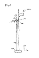
- FIG. 1 shows a wind turbine 100.
- the wind turbine has a foundation 101, by means of the wind turbine is mounted on a surface.
- a pedestal device 102 is coupled to the foundation.
- the standing device 102 is in the Z direction of FIG. 1 elongated.
- the standing device 102 is in particular a tower, for example designed as a steel tube, prestressed concrete, truss or sandwich tower.
- the nacelle comprises a generator 104 which is coupled to a rotor 109 via a rotor shaft 105.
- the rotor shaft 105 is coupled to a rotor hub 106 of the rotor 109.
- the rotor 109 further has a rotor blade 107 or a plurality of rotor blades 107, which are coupled to the rotor hub 106.
- the rotor 109 is set in operation by wind in rotation and this rotation transmitted via the rotor shaft 105 to the generator 104, which converts the kinetic energy of the rotor 109 into electrical energy.
- the nacelle 103 is coupled to the jig 102 so that the nacelle with the rotor is rotatable about the longitudinal axis of the jig 102.
- the machine house 103 is rotatably mounted on the stand device 102 via an azimuth rotary connection such that the machine house 103 and thus also the rotor shaft 105 and in particular the longitudinal axis of the rotor shaft 105 can be tracked in its horizontal orientation of the wind direction.
- the machine house 103 is aligned so that the rotor shaft 105 is aligned in the direction of the measured wind direction.
- a control device 113 is arranged, which is arranged to effect, depending on the measured wind direction 127, an alignment of the rotor.
- the control device 113 is, in embodiments, part of an arrangement 112 comprising the control device 113 and the wind energy plant 100.
- the wind direction 127 is measured, averaged and determined over a time interval of 10 minutes, for example, as the rotor hub 106 is to be tracked in the wind direction.
- the time interval is longer than 10 minutes, in yet further embodiments shorter than 10 minutes.
- the wind energy plant is aligned so that an oblique gas flow is avoided or minimized as possible.
- the wind turbine has for this purpose a device for determining the wind direction, e.g. a sensor for determining the wind direction by means of a wind vane or a 2D ultrasonic anemometer for determining the horizontal components of the wind speed and the wind direction.
- the device for determining the wind direction acquires at least measured values of the wind direction 127 and transmits these to the control device 113.
- control device 113 outputs a control signal to the azimuth drive device (not shown).
- the signal can, for example, directly be passed to a frequency converter, via which an azimuth drive is fed.
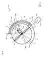
- FIG. 2 shows a system 110 of a wind turbine 100 and a radar system 111 according to an embodiment.
- the wind turbine 100 is shown in plan view.
- the radar system 111 is a weather radar system that is configured to detect precipitation, the intensity and movement of weather systems, or an air traffic control radar system for monitoring air traffic.
- the wind turbine 100 is arranged in the system 110 in an effective range of the radar system 111.
- the electromagnetic waves which are emitted by a transmitting and receiving antenna of the radar system, reach the wind energy plant 100.
- the movement of the rotor 109 and in particular of the rotor blades 107 is detected by the radar system 111.
- the rotational motion of the rotor blades has a pattern that is detected by the radar system as a weather phenomenon, such as precipitation.
- a position 125 of the radar system with respect to the wind energy plant 110 is determined.
- a straight line 126 is determined on which the radar system 111 and the rotor hub 106 lie.
- the effective range of the radar system 111 is in the region of the straight line 126.
- the effective range of the radar system surrounds the straight line 126.
- areas 121, 122 and 123, 124 (FIG. FIG. 3 ), in which an alignment of the rotor in response to the determined wind direction 127, an orientation of the axis of rotation of the rotor, in particular an orientation of the rotor shaft 105, should not be taken permanently.
- the regions 121, 122 and 123, 124 are determined in particular as a function of the straight line 126.
- less than 4 regions are determined which are avoided in the alignment of the rotor shaft 105 as a function of the determined wind direction 127, for example 2 regions.
- more than 4 regions are determined which are avoided in the alignment of the rotor shaft 105 as a function of the determined wind direction 127, for example 6 regions. This is the case in particular when the wind power plant is arranged in the effective range of two or more radar systems.
- further areas are determined by measurement, within which operation of the wind turbine proves to be disturbing the radar system.
- the area 122 is determined as a function of an angle A between the rotor shaft and the straight line 126.
- the angle A is 90 ° for the region 122.
- the size of the area about the longitudinal direction of the rotor shaft is predetermined by a further angle C.
- the angle C is the opening angle of the areas which, when the rotor shaft 105 is aligned with the longitudinal axis of the standing device 102 should not be taken permanently.
- the opening angle of the regions is in each case the same size in embodiments. In further embodiments, the opening angle of the regions is different in each case.
- the angle C specifies the width of the region 122.
- the angle C is dependent on the radar system 111 and the structural design of the wind turbine 100, in particular of the constructive shape of the rotor blades 107.
- the angle C is set so that the range 122 is so large that a significant disturbance of the radar over a longer period is avoided.
- the areas 121 and 123 and 124 are determined, the angle A has for this purpose a value of 180 ° (range 121), 270 ° (range 123) and 0 ° (range 124).
- an absolute geographic coordinate 128 is given, such as the north direction.
- the absolute geographic coordinate 128 is determined, for example, when setting up the wind turbine and stored in the control device 113.
- the regions 121, 122, 123, and 124 are determined in the embodiments as a function of the absolute geographic coordinate 128.
- An angle B between the absolute geographic coordinate 128 and the straight line 126 is determined.
- the area 122 results from the angle B - 90 °, so that an angle D is formed between the longitudinal direction of the shaft 105 and the direction of the absolute geographic coordinate 128.
- the region 121 results from the angle B + 90 °, so that an angle E is formed between the absolute geographic coordinate 128 and the middle of the region 121.
- the middle of area 124 concludes with the absolute geographical Coordinate 128 the angle B.
- the middle of the area 123 results from the angle B + 180 °.
- the areas 121 and 122 are thus determined so that the rotor hub 105 is not aligned for a long period of time so that the longitudinal direction of the rotor blades 107 is directed in the direction of the straight line 126.
- the areas are determined so that the straight line 126 is not aligned over a longer period of time in the plane of rotation of the rotor blades.
- the regions 121 and 122 indicate an orientation to be avoided for the rotor shaft 105, in which the longitudinal direction of the rotor blades 107 is in the direction of the straight line 126.
- FIG. 3 shows a rotated plan view of the system 110 of FIG. 2 .
- the regions 123 and 124 each define an alignment region of the rotor shaft 105 in which the longitudinal direction of the rotor blades 107 is transverse to the straight line 126.
- An alignment of the rotor shaft 105 in the areas 123 and 124 is avoided, so that an alignment of the rotor 109 is avoided, in which the longitudinal direction of the rotor blades 107 is transverse to the straight line 126.
- an optimal orientation of the wind turbine is determined as a function of the wind direction 127, in which the rotor shaft 105 in one of the areas 121, 122, 123 or 124 is aligned, the control device 113, the rotor shaft 105 to an edge of the corresponding area, for example, to an edge 129 of the region 122 from.
- the wind turbine is as close as possible to the optimal alignment and therefore still operable effectively.
- the radar system 111 is little influenced by the wind turbine.
- the wind turbine in particular the control device 113, is set up to provide information to the radar system 111 when, during alignment of the rotor shaft 105, one of the regions to be avoided 121, 122, 123 or 124 is traversed.
- the radar system can then take into account the disturbance by the wind turbine during this time. For example, during the time that the rotor hub 105 is in one of the regions to be avoided, the radar system 111 does not evaluate the radar signals.
- the opening angle C of the area 122 is 16 °, that is from -8 to + 8 °, and the wind turbine is operated so that it is aligned in the direction of + 9 ° with respect to the center of the area 122 and is over a time interval of 10 minutes determines that the wind direction has set on average to -9 ° with respect to the center of the area 122, it is permissible to track the rotor hub 105 through the area to be avoided 122. For example, it is found that the wind direction averages -2 ° with respect to the center of the area 122 has set, the plant in its orientation to - 8 °, so the nearest edge 129 of the area 122, be tracked. In this way, an oblique flow is minimized taking into account an area to be avoided.
Landscapes
- Engineering & Computer Science (AREA)
- Life Sciences & Earth Sciences (AREA)
- Sustainable Development (AREA)
- Sustainable Energy (AREA)
- Chemical & Material Sciences (AREA)
- Combustion & Propulsion (AREA)
- Mechanical Engineering (AREA)
- General Engineering & Computer Science (AREA)
- Radar Systems Or Details Thereof (AREA)
- Wind Motors (AREA)
Priority Applications (4)
| Application Number | Priority Date | Filing Date | Title |
|---|---|---|---|
| PL11152546T PL2481918T3 (pl) | 2011-01-28 | 2011-01-28 | Sposób eksploatacji silnika wiatrowego w zakresie działania radaru |
| EP11152546.5A EP2481918B1 (fr) | 2011-01-28 | 2011-01-28 | Procédé de fonctionnement d'une éolienne dans un lieu d'effet du RADAR |
| US13/350,916 US9033660B2 (en) | 2011-01-28 | 2012-01-16 | Method for operating a wind turbine, arrangement and system |
| CN201210020275.2A CN102619689B (zh) | 2011-01-28 | 2012-01-29 | 用于运行风轮机的方法、构造和系统 |
Applications Claiming Priority (1)
| Application Number | Priority Date | Filing Date | Title |
|---|---|---|---|
| EP11152546.5A EP2481918B1 (fr) | 2011-01-28 | 2011-01-28 | Procédé de fonctionnement d'une éolienne dans un lieu d'effet du RADAR |
Publications (2)
| Publication Number | Publication Date |
|---|---|
| EP2481918A1 true EP2481918A1 (fr) | 2012-08-01 |
| EP2481918B1 EP2481918B1 (fr) | 2015-08-26 |
Family
ID=44170574
Family Applications (1)
| Application Number | Title | Priority Date | Filing Date |
|---|---|---|---|
| EP11152546.5A Active EP2481918B1 (fr) | 2011-01-28 | 2011-01-28 | Procédé de fonctionnement d'une éolienne dans un lieu d'effet du RADAR |
Country Status (4)
| Country | Link |
|---|---|
| US (1) | US9033660B2 (fr) |
| EP (1) | EP2481918B1 (fr) |
| CN (1) | CN102619689B (fr) |
| PL (1) | PL2481918T3 (fr) |
Cited By (2)
| Publication number | Priority date | Publication date | Assignee | Title |
|---|---|---|---|---|
| EP2725225A3 (fr) * | 2012-10-24 | 2016-10-26 | Senvion GmbH | Installation éolienne dotée d'une réflexion radar réduite |
| CN108387881A (zh) * | 2018-02-01 | 2018-08-10 | 三峡大学 | 一种风电机叶片回波的精确仿真算法 |
Families Citing this family (2)
| Publication number | Priority date | Publication date | Assignee | Title |
|---|---|---|---|---|
| WO2018093445A1 (fr) * | 2016-09-01 | 2018-05-24 | Colorado State University Research Foundation | Suppression de signatures radar à variation cyclique dans le temps |
| DE102019114916A1 (de) * | 2019-06-04 | 2020-12-10 | WuF- Windenergie und Flugsicherheit GmbH | Verfahren, Anordnung und System zum Betreiben von Windenergieanlagen in der Nähe eines Flugbewegungen überwachenden Radarsystems |
Citations (6)
| Publication number | Priority date | Publication date | Assignee | Title |
|---|---|---|---|---|
| US7302903B1 (en) * | 2004-07-23 | 2007-12-04 | Rudolph Behrens | Floating vessel for producing hydrocarbons and method for producing hydrocarbons |
| US20090202347A1 (en) * | 2008-02-08 | 2009-08-13 | Technology Service Corporation | Systems and methods for mitigating the effects of wind turbines on radar |
| WO2009144435A1 (fr) * | 2008-05-29 | 2009-12-03 | Cambridge Consultants Limited | Système radar et procédé correspondant |
| WO2010099773A1 (fr) | 2009-03-06 | 2010-09-10 | Eads Deutschland Gmbh | Procédé de détection d'éoliennes au moyen d'une installation radar |
| WO2010109174A1 (fr) | 2009-03-27 | 2010-09-30 | Qinetiq Limited | Composition absorbant les champs électromagnétiques |
| WO2010122350A1 (fr) | 2009-04-23 | 2010-10-28 | Vestas Wind Systems A/S | Incorporation de tissu fonctionnel dans les composites pré-imprégnés |
Family Cites Families (13)
| Publication number | Priority date | Publication date | Assignee | Title |
|---|---|---|---|---|
| US2484291A (en) * | 1945-07-13 | 1949-10-11 | Russell R Hays | Wind rotor |
| DK140382B (da) * | 1977-07-25 | 1979-08-13 | Peder Ulrik Poulsen | Vindmotor. |
| DE2737767C2 (de) * | 1977-08-22 | 1979-05-17 | Ulrich Prof. Dr.-Ing. 7312 Kirchheim Huetter | Windkraftanlage |
| US4449889A (en) * | 1983-01-20 | 1984-05-22 | Belden Ralph A | Windmill |
| DE10153403B4 (de) * | 2001-11-01 | 2013-07-18 | Aloys Wobben | Windpark |
| EP1830447A1 (fr) | 2006-03-02 | 2007-09-05 | ABB Research Ltd | Unité de contrôle pour un convertisseur utilisant des vecteurs de tension ou de courant avec chronotimbre |
| US7417332B2 (en) | 2006-08-24 | 2008-08-26 | General Electric Company | Method and apparatus of monitoring a machine |
| US7551130B2 (en) | 2007-11-21 | 2009-06-23 | General Electric Company | Wind turbine with data receiver |
| DE102008020154B4 (de) * | 2008-04-22 | 2011-04-28 | Repower Systems Ag | Verfahren zum Betreiben einer Windenergieanlage |
| DE102008024644B4 (de) | 2008-05-21 | 2018-07-26 | Airbus Defence and Space GmbH | Rotorblatt mit darin integriertem Radarabsorber für eine Windkraftanlage |
| CA2739099A1 (fr) | 2008-10-06 | 2010-04-15 | Flodesign Wind Turbine Corporation | Eolienne presentant une signature radar reduite |
| GB0822468D0 (en) | 2008-12-10 | 2009-01-14 | Qinetiq Ltd | Method for mitigating the effects of clutter and interference on a radar system |
| WO2010098814A1 (fr) * | 2009-02-28 | 2010-09-02 | Ener2 Llc | Dispositif amélioré à énergie éolienne |
-
2011
- 2011-01-28 EP EP11152546.5A patent/EP2481918B1/fr active Active
- 2011-01-28 PL PL11152546T patent/PL2481918T3/pl unknown
-
2012
- 2012-01-16 US US13/350,916 patent/US9033660B2/en active Active
- 2012-01-29 CN CN201210020275.2A patent/CN102619689B/zh not_active Expired - Fee Related
Patent Citations (6)
| Publication number | Priority date | Publication date | Assignee | Title |
|---|---|---|---|---|
| US7302903B1 (en) * | 2004-07-23 | 2007-12-04 | Rudolph Behrens | Floating vessel for producing hydrocarbons and method for producing hydrocarbons |
| US20090202347A1 (en) * | 2008-02-08 | 2009-08-13 | Technology Service Corporation | Systems and methods for mitigating the effects of wind turbines on radar |
| WO2009144435A1 (fr) * | 2008-05-29 | 2009-12-03 | Cambridge Consultants Limited | Système radar et procédé correspondant |
| WO2010099773A1 (fr) | 2009-03-06 | 2010-09-10 | Eads Deutschland Gmbh | Procédé de détection d'éoliennes au moyen d'une installation radar |
| WO2010109174A1 (fr) | 2009-03-27 | 2010-09-30 | Qinetiq Limited | Composition absorbant les champs électromagnétiques |
| WO2010122350A1 (fr) | 2009-04-23 | 2010-10-28 | Vestas Wind Systems A/S | Incorporation de tissu fonctionnel dans les composites pré-imprégnés |
Non-Patent Citations (2)
| Title |
|---|
| CIVIL AVIATION AUTHORITY: "CAA Policy and Guidelines on Wind Turbines", INTERNET CITATION, 1 July 2006 (2006-07-01), pages 1 - 66, XP007918986, ISBN: 978-0-11-792406-2, Retrieved from the Internet <URL:http://www.caa.co.uk/docs/33/Cap764.pdf> [retrieved on 20110704] * |
| DEPARTMENT OF TRADE AND INDUSTRY: "FEASIBILITY OF MITIGATING THE EFFECTS OF WINDFARMS ON PRIMARY RADAR", INTERNET CITATION, 1 January 2003 (2003-01-01), pages 1 - 71, XP007918988, Retrieved from the Internet <URL:http://www.bwea.com/aviation/ams_report.html> [retrieved on 20110704] * |
Cited By (2)
| Publication number | Priority date | Publication date | Assignee | Title |
|---|---|---|---|---|
| EP2725225A3 (fr) * | 2012-10-24 | 2016-10-26 | Senvion GmbH | Installation éolienne dotée d'une réflexion radar réduite |
| CN108387881A (zh) * | 2018-02-01 | 2018-08-10 | 三峡大学 | 一种风电机叶片回波的精确仿真算法 |
Also Published As
| Publication number | Publication date |
|---|---|
| PL2481918T3 (pl) | 2016-02-29 |
| US9033660B2 (en) | 2015-05-19 |
| US20120195756A1 (en) | 2012-08-02 |
| EP2481918B1 (fr) | 2015-08-26 |
| CN102619689B (zh) | 2014-10-22 |
| CN102619689A (zh) | 2012-08-01 |
Similar Documents
| Publication | Publication Date | Title |
|---|---|---|
| DE602005003341T2 (de) | Eine Vorrichtung und ein Verfahren zum Bestimmen der Geschwindigkeit und der Richtung des Windes, dem eine Windturbine ausgesetzt ist | |
| EP1432911B1 (fr) | Systeme d'alerte rapide pour installations d'energie eolienne a sodar | |
| EP0335009A2 (fr) | Procédé pour acquérir et traiter des données de trafic local et dispositif pour exécuter le procédé | |
| EP3298272B1 (fr) | Dispositif de mesure situé sur une éolienne | |
| EP2357359A2 (fr) | Détection d'une déformation d'une pale d'éolienne | |
| WO2002002936A1 (fr) | Procede pour determiner l'angle d'une pale de rotor d'une installation a energie eolienne | |
| EP2481918B1 (fr) | Procédé de fonctionnement d'une éolienne dans un lieu d'effet du RADAR | |
| DE102015122126A1 (de) | Verfahren zum Bestimmen eines Azimutwinkels einer Windenergieanlage | |
| Norin | A quantitative analysis of the impact of wind turbines on operational Doppler weather radar data | |
| DE602004001726T2 (de) | Windkraftanlage mit waagerechter Welle und Verfahren zur Messung des Aufwärtsströmungswinkels | |
| EP3361094A1 (fr) | Éolienne et parc éolien comprenant au moins une telle éolienne | |
| EP2674616B1 (fr) | Dispositif de commande d'installation éolienne et système de commande d'un parc éolien | |
| DE102018116941B4 (de) | Vorrichtung und Verfahren zum Erkennen der Anlagerung oder der Eisart von Eis an einem Rotorblatt eines Rotors einer Windkraftanlage | |
| US11421651B2 (en) | Method of determining wind direction by means of a LiDAR sensor | |
| DE102008013392B4 (de) | Verfahren zum Erfassen des Spurlaufes der Rotorblätter einer Windkraftanlage | |
| EP2404190B1 (fr) | Procédé de détection d'éoliennes au moyen d'une installation radar | |
| EP2719624B1 (fr) | Procédé d'exploitation d'une éolienne et éolienne destinée à l'exécution du procédé | |
| DE102012015456A1 (de) | Vorrichtung und Verfahren zum Erfassen einer Verformung zumindest eines Rotorblatts eines Rotors einer Windenergieanlage | |
| EP3788385B1 (fr) | Éolienne | |
| DE102015009704A1 (de) | Steuerung und Steuerungsverfahren für eine Windenergieanlage | |
| EP3538758B1 (fr) | Système de mesure et procédé permettant de détecter un givrage sur des pales de rotor d'éolienne | |
| Gallacher et al. | Lidar measurements and visualisation of turbulence and wake decay length | |
| DE102012024272A1 (de) | Verfahren und Vorrichtung zum Verringern eines Rotors einer Windenergieanlage belastenden Nickmoments | |
| EP2481919A1 (fr) | Procédé de fonctionnement d'une éolienne, agencement et système | |
| EP1750141B1 (fr) | Dispositif destiné à la simulation d'une cible de radar mobile |
Legal Events
| Date | Code | Title | Description |
|---|---|---|---|
| PUAI | Public reference made under article 153(3) epc to a published international application that has entered the european phase |
Free format text: ORIGINAL CODE: 0009012 |
|
| AK | Designated contracting states |
Kind code of ref document: A1 Designated state(s): AL AT BE BG CH CY CZ DE DK EE ES FI FR GB GR HR HU IE IS IT LI LT LU LV MC MK MT NL NO PL PT RO RS SE SI SK SM TR |
|
| AX | Request for extension of the european patent |
Extension state: BA ME |
|
| 17P | Request for examination filed |
Effective date: 20130111 |
|
| RAP1 | Party data changed (applicant data changed or rights of an application transferred) |
Owner name: NORDEX ENERGY GMBH |
|
| 17Q | First examination report despatched |
Effective date: 20130816 |
|
| GRAP | Despatch of communication of intention to grant a patent |
Free format text: ORIGINAL CODE: EPIDOSNIGR1 |
|
| INTG | Intention to grant announced |
Effective date: 20150511 |
|
| GRAS | Grant fee paid |
Free format text: ORIGINAL CODE: EPIDOSNIGR3 |
|
| GRAA | (expected) grant |
Free format text: ORIGINAL CODE: 0009210 |
|
| AK | Designated contracting states |
Kind code of ref document: B1 Designated state(s): AL AT BE BG CH CY CZ DE DK EE ES FI FR GB GR HR HU IE IS IT LI LT LU LV MC MK MT NL NO PL PT RO RS SE SI SK SM TR |
|
| REG | Reference to a national code |
Ref country code: GB Ref legal event code: FG4D Free format text: NOT ENGLISH |
|
| REG | Reference to a national code |
Ref country code: CH Ref legal event code: EP |
|
| REG | Reference to a national code |
Ref country code: AT Ref legal event code: REF Ref document number: 745326 Country of ref document: AT Kind code of ref document: T Effective date: 20150915 |
|
| REG | Reference to a national code |
Ref country code: IE Ref legal event code: FG4D Free format text: LANGUAGE OF EP DOCUMENT: GERMAN |
|
| REG | Reference to a national code |
Ref country code: DE Ref legal event code: R096 Ref document number: 502011007677 Country of ref document: DE |
|
| REG | Reference to a national code |
Ref country code: SE Ref legal event code: TRGR |
|
| REG | Reference to a national code |
Ref country code: FR Ref legal event code: PLFP Year of fee payment: 6 |
|
| REG | Reference to a national code |
Ref country code: LT Ref legal event code: MG4D |
|
| REG | Reference to a national code |
Ref country code: NL Ref legal event code: FP |
|
| PG25 | Lapsed in a contracting state [announced via postgrant information from national office to epo] |
Ref country code: NO Free format text: LAPSE BECAUSE OF FAILURE TO SUBMIT A TRANSLATION OF THE DESCRIPTION OR TO PAY THE FEE WITHIN THE PRESCRIBED TIME-LIMIT Effective date: 20151126 Ref country code: LT Free format text: LAPSE BECAUSE OF FAILURE TO SUBMIT A TRANSLATION OF THE DESCRIPTION OR TO PAY THE FEE WITHIN THE PRESCRIBED TIME-LIMIT Effective date: 20150826 Ref country code: GR Free format text: LAPSE BECAUSE OF FAILURE TO SUBMIT A TRANSLATION OF THE DESCRIPTION OR TO PAY THE FEE WITHIN THE PRESCRIBED TIME-LIMIT Effective date: 20151127 Ref country code: LV Free format text: LAPSE BECAUSE OF FAILURE TO SUBMIT A TRANSLATION OF THE DESCRIPTION OR TO PAY THE FEE WITHIN THE PRESCRIBED TIME-LIMIT Effective date: 20150826 |
|
| PG25 | Lapsed in a contracting state [announced via postgrant information from national office to epo] |
Ref country code: RS Free format text: LAPSE BECAUSE OF FAILURE TO SUBMIT A TRANSLATION OF THE DESCRIPTION OR TO PAY THE FEE WITHIN THE PRESCRIBED TIME-LIMIT Effective date: 20150826 Ref country code: HR Free format text: LAPSE BECAUSE OF FAILURE TO SUBMIT A TRANSLATION OF THE DESCRIPTION OR TO PAY THE FEE WITHIN THE PRESCRIBED TIME-LIMIT Effective date: 20150826 Ref country code: PT Free format text: LAPSE BECAUSE OF FAILURE TO SUBMIT A TRANSLATION OF THE DESCRIPTION OR TO PAY THE FEE WITHIN THE PRESCRIBED TIME-LIMIT Effective date: 20151228 Ref country code: ES Free format text: LAPSE BECAUSE OF FAILURE TO SUBMIT A TRANSLATION OF THE DESCRIPTION OR TO PAY THE FEE WITHIN THE PRESCRIBED TIME-LIMIT Effective date: 20150826 Ref country code: IS Free format text: LAPSE BECAUSE OF FAILURE TO SUBMIT A TRANSLATION OF THE DESCRIPTION OR TO PAY THE FEE WITHIN THE PRESCRIBED TIME-LIMIT Effective date: 20151226 |
|
| PG25 | Lapsed in a contracting state [announced via postgrant information from national office to epo] |
Ref country code: EE Free format text: LAPSE BECAUSE OF FAILURE TO SUBMIT A TRANSLATION OF THE DESCRIPTION OR TO PAY THE FEE WITHIN THE PRESCRIBED TIME-LIMIT Effective date: 20150826 Ref country code: SK Free format text: LAPSE BECAUSE OF FAILURE TO SUBMIT A TRANSLATION OF THE DESCRIPTION OR TO PAY THE FEE WITHIN THE PRESCRIBED TIME-LIMIT Effective date: 20150826 Ref country code: IT Free format text: LAPSE BECAUSE OF FAILURE TO SUBMIT A TRANSLATION OF THE DESCRIPTION OR TO PAY THE FEE WITHIN THE PRESCRIBED TIME-LIMIT Effective date: 20150826 Ref country code: CZ Free format text: LAPSE BECAUSE OF FAILURE TO SUBMIT A TRANSLATION OF THE DESCRIPTION OR TO PAY THE FEE WITHIN THE PRESCRIBED TIME-LIMIT Effective date: 20150826 Ref country code: DK Free format text: LAPSE BECAUSE OF FAILURE TO SUBMIT A TRANSLATION OF THE DESCRIPTION OR TO PAY THE FEE WITHIN THE PRESCRIBED TIME-LIMIT Effective date: 20150826 |
|
| REG | Reference to a national code |
Ref country code: DE Ref legal event code: R097 Ref document number: 502011007677 Country of ref document: DE |
|
| PG25 | Lapsed in a contracting state [announced via postgrant information from national office to epo] |
Ref country code: RO Free format text: LAPSE BECAUSE OF FAILURE TO SUBMIT A TRANSLATION OF THE DESCRIPTION OR TO PAY THE FEE WITHIN THE PRESCRIBED TIME-LIMIT Effective date: 20150826 Ref country code: BE Free format text: LAPSE BECAUSE OF NON-PAYMENT OF DUE FEES Effective date: 20160131 |
|
| PLBE | No opposition filed within time limit |
Free format text: ORIGINAL CODE: 0009261 |
|
| STAA | Information on the status of an ep patent application or granted ep patent |
Free format text: STATUS: NO OPPOSITION FILED WITHIN TIME LIMIT |
|
| 26N | No opposition filed |
Effective date: 20160530 |
|
| PG25 | Lapsed in a contracting state [announced via postgrant information from national office to epo] |
Ref country code: LU Free format text: LAPSE BECAUSE OF FAILURE TO SUBMIT A TRANSLATION OF THE DESCRIPTION OR TO PAY THE FEE WITHIN THE PRESCRIBED TIME-LIMIT Effective date: 20160128 Ref country code: SI Free format text: LAPSE BECAUSE OF FAILURE TO SUBMIT A TRANSLATION OF THE DESCRIPTION OR TO PAY THE FEE WITHIN THE PRESCRIBED TIME-LIMIT Effective date: 20150826 |
|
| REG | Reference to a national code |
Ref country code: CH Ref legal event code: PL |
|
| PG25 | Lapsed in a contracting state [announced via postgrant information from national office to epo] |
Ref country code: MC Free format text: LAPSE BECAUSE OF FAILURE TO SUBMIT A TRANSLATION OF THE DESCRIPTION OR TO PAY THE FEE WITHIN THE PRESCRIBED TIME-LIMIT Effective date: 20150826 |
|
| PG25 | Lapsed in a contracting state [announced via postgrant information from national office to epo] |
Ref country code: CH Free format text: LAPSE BECAUSE OF NON-PAYMENT OF DUE FEES Effective date: 20160131 Ref country code: LI Free format text: LAPSE BECAUSE OF NON-PAYMENT OF DUE FEES Effective date: 20160131 |
|
| REG | Reference to a national code |
Ref country code: FR Ref legal event code: PLFP Year of fee payment: 7 |
|
| REG | Reference to a national code |
Ref country code: AT Ref legal event code: MM01 Ref document number: 745326 Country of ref document: AT Kind code of ref document: T Effective date: 20160128 |
|
| PGFP | Annual fee paid to national office [announced via postgrant information from national office to epo] |
Ref country code: NL Payment date: 20170124 Year of fee payment: 7 |
|
| PGFP | Annual fee paid to national office [announced via postgrant information from national office to epo] |
Ref country code: FI Payment date: 20170120 Year of fee payment: 7 |
|
| PG25 | Lapsed in a contracting state [announced via postgrant information from national office to epo] |
Ref country code: AT Free format text: LAPSE BECAUSE OF NON-PAYMENT OF DUE FEES Effective date: 20160128 |
|
| PGFP | Annual fee paid to national office [announced via postgrant information from national office to epo] |
Ref country code: PL Payment date: 20170113 Year of fee payment: 7 Ref country code: IE Payment date: 20170123 Year of fee payment: 7 |
|
| PGFP | Annual fee paid to national office [announced via postgrant information from national office to epo] |
Ref country code: TR Payment date: 20170120 Year of fee payment: 7 |
|
| PG25 | Lapsed in a contracting state [announced via postgrant information from national office to epo] |
Ref country code: MT Free format text: LAPSE BECAUSE OF FAILURE TO SUBMIT A TRANSLATION OF THE DESCRIPTION OR TO PAY THE FEE WITHIN THE PRESCRIBED TIME-LIMIT Effective date: 20150826 |
|
| REG | Reference to a national code |
Ref country code: FR Ref legal event code: PLFP Year of fee payment: 8 |
|
| PG25 | Lapsed in a contracting state [announced via postgrant information from national office to epo] |
Ref country code: HU Free format text: LAPSE BECAUSE OF FAILURE TO SUBMIT A TRANSLATION OF THE DESCRIPTION OR TO PAY THE FEE WITHIN THE PRESCRIBED TIME-LIMIT; INVALID AB INITIO Effective date: 20110128 Ref country code: CY Free format text: LAPSE BECAUSE OF FAILURE TO SUBMIT A TRANSLATION OF THE DESCRIPTION OR TO PAY THE FEE WITHIN THE PRESCRIBED TIME-LIMIT Effective date: 20150826 Ref country code: SM Free format text: LAPSE BECAUSE OF FAILURE TO SUBMIT A TRANSLATION OF THE DESCRIPTION OR TO PAY THE FEE WITHIN THE PRESCRIBED TIME-LIMIT Effective date: 20150826 |
|
| PG25 | Lapsed in a contracting state [announced via postgrant information from national office to epo] |
Ref country code: MK Free format text: LAPSE BECAUSE OF FAILURE TO SUBMIT A TRANSLATION OF THE DESCRIPTION OR TO PAY THE FEE WITHIN THE PRESCRIBED TIME-LIMIT Effective date: 20150826 |
|
| PG25 | Lapsed in a contracting state [announced via postgrant information from national office to epo] |
Ref country code: BG Free format text: LAPSE BECAUSE OF FAILURE TO SUBMIT A TRANSLATION OF THE DESCRIPTION OR TO PAY THE FEE WITHIN THE PRESCRIBED TIME-LIMIT Effective date: 20150826 |
|
| REG | Reference to a national code |
Ref country code: NL Ref legal event code: MM Effective date: 20180201 |
|
| PG25 | Lapsed in a contracting state [announced via postgrant information from national office to epo] |
Ref country code: AL Free format text: LAPSE BECAUSE OF FAILURE TO SUBMIT A TRANSLATION OF THE DESCRIPTION OR TO PAY THE FEE WITHIN THE PRESCRIBED TIME-LIMIT Effective date: 20150826 Ref country code: FI Free format text: LAPSE BECAUSE OF NON-PAYMENT OF DUE FEES Effective date: 20180128 |
|
| REG | Reference to a national code |
Ref country code: IE Ref legal event code: MM4A |
|
| PG25 | Lapsed in a contracting state [announced via postgrant information from national office to epo] |
Ref country code: NL Free format text: LAPSE BECAUSE OF NON-PAYMENT OF DUE FEES Effective date: 20180201 |
|
| PG25 | Lapsed in a contracting state [announced via postgrant information from national office to epo] |
Ref country code: IE Free format text: LAPSE BECAUSE OF NON-PAYMENT OF DUE FEES Effective date: 20180128 |
|
| PG25 | Lapsed in a contracting state [announced via postgrant information from national office to epo] |
Ref country code: PL Free format text: LAPSE BECAUSE OF NON-PAYMENT OF DUE FEES Effective date: 20180128 |
|
| REG | Reference to a national code |
Ref country code: DE Ref legal event code: R082 Ref document number: 502011007677 Country of ref document: DE Representative=s name: EPPING HERMANN FISCHER PATENTANWALTSGESELLSCHA, DE Ref country code: DE Ref legal event code: R081 Ref document number: 502011007677 Country of ref document: DE Owner name: NORDEX ENERGY SE & CO. KG, DE Free format text: FORMER OWNER: NORDEX ENERGY GMBH, 22419 HAMBURG, DE |
|
| PG25 | Lapsed in a contracting state [announced via postgrant information from national office to epo] |
Ref country code: TR Free format text: LAPSE BECAUSE OF NON-PAYMENT OF DUE FEES Effective date: 20180128 |
|
| PGFP | Annual fee paid to national office [announced via postgrant information from national office to epo] |
Ref country code: SE Payment date: 20230123 Year of fee payment: 13 Ref country code: GB Payment date: 20230124 Year of fee payment: 13 Ref country code: DE Payment date: 20230119 Year of fee payment: 13 |
|
| P01 | Opt-out of the competence of the unified patent court (upc) registered |
Effective date: 20230515 |
|
| REG | Reference to a national code |
Ref country code: DE Ref legal event code: R119 Ref document number: 502011007677 Country of ref document: DE |
|
| REG | Reference to a national code |
Ref country code: SE Ref legal event code: EUG |
|
| GBPC | Gb: european patent ceased through non-payment of renewal fee |
Effective date: 20240128 |
|
| PG25 | Lapsed in a contracting state [announced via postgrant information from national office to epo] |
Ref country code: DE Free format text: LAPSE BECAUSE OF NON-PAYMENT OF DUE FEES Effective date: 20240801 |
|
| PG25 | Lapsed in a contracting state [announced via postgrant information from national office to epo] |
Ref country code: GB Free format text: LAPSE BECAUSE OF NON-PAYMENT OF DUE FEES Effective date: 20240128 |
|
| PG25 | Lapsed in a contracting state [announced via postgrant information from national office to epo] |
Ref country code: GB Free format text: LAPSE BECAUSE OF NON-PAYMENT OF DUE FEES Effective date: 20240128 Ref country code: DE Free format text: LAPSE BECAUSE OF NON-PAYMENT OF DUE FEES Effective date: 20240801 |
|
| PG25 | Lapsed in a contracting state [announced via postgrant information from national office to epo] |
Ref country code: SE Free format text: LAPSE BECAUSE OF NON-PAYMENT OF DUE FEES Effective date: 20240129 |
|
| PGFP | Annual fee paid to national office [announced via postgrant information from national office to epo] |
Ref country code: FR Payment date: 20260127 Year of fee payment: 16 |