EP2482018A1 - Türvorrichtung zur abgabe von schlacke für einen elektroofen - Google Patents
Türvorrichtung zur abgabe von schlacke für einen elektroofen Download PDFInfo
- Publication number
- EP2482018A1 EP2482018A1 EP10841099A EP10841099A EP2482018A1 EP 2482018 A1 EP2482018 A1 EP 2482018A1 EP 10841099 A EP10841099 A EP 10841099A EP 10841099 A EP10841099 A EP 10841099A EP 2482018 A1 EP2482018 A1 EP 2482018A1
- Authority
- EP
- European Patent Office
- Prior art keywords
- door
- slag
- slag discharge
- stepped portion
- solidified
- Prior art date
- Legal status (The legal status is an assumption and is not a legal conclusion. Google has not performed a legal analysis and makes no representation as to the accuracy of the status listed.)
- Withdrawn
Links
- 239000002893 slag Substances 0.000 title claims abstract description 163
- 239000002826 coolant Substances 0.000 claims description 22
- 229910000831 Steel Inorganic materials 0.000 description 8
- 239000010959 steel Substances 0.000 description 8
- 239000000498 cooling water Substances 0.000 description 7
- UQSXHKLRYXJYBZ-UHFFFAOYSA-N Iron oxide Chemical compound [Fe]=O UQSXHKLRYXJYBZ-UHFFFAOYSA-N 0.000 description 4
- 239000012535 impurity Substances 0.000 description 4
- 230000003647 oxidation Effects 0.000 description 4
- 238000007254 oxidation reaction Methods 0.000 description 4
- 238000009628 steelmaking Methods 0.000 description 4
- 239000010953 base metal Substances 0.000 description 3
- 239000002184 metal Substances 0.000 description 2
- 229910052751 metal Inorganic materials 0.000 description 2
- 229910044991 metal oxide Inorganic materials 0.000 description 2
- 150000004706 metal oxides Chemical class 0.000 description 2
- 238000012986 modification Methods 0.000 description 2
- 230000004048 modification Effects 0.000 description 2
- 238000007670 refining Methods 0.000 description 2
- 238000007711 solidification Methods 0.000 description 2
- 230000008023 solidification Effects 0.000 description 2
- 238000007792 addition Methods 0.000 description 1
- 239000000956 alloy Substances 0.000 description 1
- 229910045601 alloy Inorganic materials 0.000 description 1
- 239000006227 byproduct Substances 0.000 description 1
- 238000001816 cooling Methods 0.000 description 1
- 230000000994 depressogenic effect Effects 0.000 description 1
- 230000000694 effects Effects 0.000 description 1
- 238000010891 electric arc Methods 0.000 description 1
- 238000010438 heat treatment Methods 0.000 description 1
- 238000000034 method Methods 0.000 description 1
- 238000006467 substitution reaction Methods 0.000 description 1
- -1 that is Substances 0.000 description 1
Images




Classifications
-
- C—CHEMISTRY; METALLURGY
- C21—METALLURGY OF IRON
- C21C—PROCESSING OF PIG-IRON, e.g. REFINING, MANUFACTURE OF WROUGHT-IRON OR STEEL; TREATMENT IN MOLTEN STATE OF FERROUS ALLOYS
- C21C5/00—Manufacture of carbon-steel, e.g. plain mild steel, medium carbon steel or cast steel or stainless steel
- C21C5/52—Manufacture of steel in electric furnaces
-
- F—MECHANICAL ENGINEERING; LIGHTING; HEATING; WEAPONS; BLASTING
- F27—FURNACES; KILNS; OVENS; RETORTS
- F27D—DETAILS OR ACCESSORIES OF FURNACES, KILNS, OVENS OR RETORTS, IN SO FAR AS THEY ARE OF KINDS OCCURRING IN MORE THAN ONE KIND OF FURNACE
- F27D1/00—Casings; Linings; Walls; Roofs
- F27D1/18—Door frames; Doors, lids or removable covers
- F27D1/1858—Doors
-
- F—MECHANICAL ENGINEERING; LIGHTING; HEATING; WEAPONS; BLASTING
- F27—FURNACES; KILNS; OVENS; RETORTS
- F27B—FURNACES, KILNS, OVENS OR RETORTS IN GENERAL; OPEN SINTERING OR LIKE APPARATUS
- F27B3/00—Hearth-type furnaces, e.g. of reverberatory type; Electric arc furnaces ; Tank furnaces
- F27B3/08—Hearth-type furnaces, e.g. of reverberatory type; Electric arc furnaces ; Tank furnaces heated electrically, with or without any other source of heat
-
- F—MECHANICAL ENGINEERING; LIGHTING; HEATING; WEAPONS; BLASTING
- F27—FURNACES; KILNS; OVENS; RETORTS
- F27B—FURNACES, KILNS, OVENS OR RETORTS IN GENERAL; OPEN SINTERING OR LIKE APPARATUS
- F27B3/00—Hearth-type furnaces, e.g. of reverberatory type; Electric arc furnaces ; Tank furnaces
- F27B3/10—Details, accessories or equipment, e.g. dust-collectors, specially adapted for hearth-type furnaces
-
- F—MECHANICAL ENGINEERING; LIGHTING; HEATING; WEAPONS; BLASTING
- F27—FURNACES; KILNS; OVENS; RETORTS
- F27B—FURNACES, KILNS, OVENS OR RETORTS IN GENERAL; OPEN SINTERING OR LIKE APPARATUS
- F27B3/00—Hearth-type furnaces, e.g. of reverberatory type; Electric arc furnaces ; Tank furnaces
- F27B3/10—Details, accessories or equipment, e.g. dust-collectors, specially adapted for hearth-type furnaces
- F27B3/105—Slag chamber
-
- F—MECHANICAL ENGINEERING; LIGHTING; HEATING; WEAPONS; BLASTING
- F27—FURNACES; KILNS; OVENS; RETORTS
- F27B—FURNACES, KILNS, OVENS OR RETORTS IN GENERAL; OPEN SINTERING OR LIKE APPARATUS
- F27B3/00—Hearth-type furnaces, e.g. of reverberatory type; Electric arc furnaces ; Tank furnaces
- F27B3/10—Details, accessories or equipment, e.g. dust-collectors, specially adapted for hearth-type furnaces
- F27B3/19—Arrangements of devices for discharging
-
- F—MECHANICAL ENGINEERING; LIGHTING; HEATING; WEAPONS; BLASTING
- F27—FURNACES; KILNS; OVENS; RETORTS
- F27D—DETAILS OR ACCESSORIES OF FURNACES, KILNS, OVENS OR RETORTS, IN SO FAR AS THEY ARE OF KINDS OCCURRING IN MORE THAN ONE KIND OF FURNACE
- F27D1/00—Casings; Linings; Walls; Roofs
- F27D1/18—Door frames; Doors, lids or removable covers
-
- F—MECHANICAL ENGINEERING; LIGHTING; HEATING; WEAPONS; BLASTING
- F27—FURNACES; KILNS; OVENS; RETORTS
- F27D—DETAILS OR ACCESSORIES OF FURNACES, KILNS, OVENS OR RETORTS, IN SO FAR AS THEY ARE OF KINDS OCCURRING IN MORE THAN ONE KIND OF FURNACE
- F27D1/00—Casings; Linings; Walls; Roofs
- F27D1/18—Door frames; Doors, lids or removable covers
- F27D1/1858—Doors
- F27D1/1866—Door-frames
-
- F—MECHANICAL ENGINEERING; LIGHTING; HEATING; WEAPONS; BLASTING
- F27—FURNACES; KILNS; OVENS; RETORTS
- F27D—DETAILS OR ACCESSORIES OF FURNACES, KILNS, OVENS OR RETORTS, IN SO FAR AS THEY ARE OF KINDS OCCURRING IN MORE THAN ONE KIND OF FURNACE
- F27D3/00—Charging; Discharging; Manipulation of charge
- F27D3/15—Tapping equipment; Equipment for removing or retaining slag
- F27D3/1545—Equipment for removing or retaining slag
-
- F—MECHANICAL ENGINEERING; LIGHTING; HEATING; WEAPONS; BLASTING
- F27—FURNACES; KILNS; OVENS; RETORTS
- F27D—DETAILS OR ACCESSORIES OF FURNACES, KILNS, OVENS OR RETORTS, IN SO FAR AS THEY ARE OF KINDS OCCURRING IN MORE THAN ONE KIND OF FURNACE
- F27D1/00—Casings; Linings; Walls; Roofs
- F27D1/18—Door frames; Doors, lids or removable covers
- F27D1/1858—Doors
- F27D2001/1875—Hanging doors and walls
Definitions
- the present invention relates generally to a slag discharge door apparatus for an electric furnace, and, more particularly, to a slag discharge door apparatus which is configured so that initial slag is prevented from leaking out of a slag discharge outlet of the electric furnace.
- electric furnaces heat and melt metal or alloys using electric energy.
- scraps are inserted into the furnace and then arc currents are applied between three electrodes and the scraps, thus heating the scraps to melt them.
- Slag is formed on an upper surface of molten steel in the electric furnace by oxidation of impurities contained in the scraps.
- the slag isolates the molten steel in the electric furnace from the air, thus retaining arc-generating heat, and preventing the molten steel from adsorbing impurities contained in the air.
- the slag functions to enhance the power efficiency of the furnace and to improve the quality of the steel.
- an object of the present invention is to provide a slag discharge door apparatus for an electric furnace which is configured inhibit slag from leaking out of the electric furnace when steelmaking.
- the present invention provides a slag discharge door apparatus for an electric furnace, including: a door opening and closing a slag discharge outlet of the electric furnace; a door support disposed so that a portion of a lower end of the door overlaps with the door support; and a door operator operating the door to open or close the slag discharge outlet, wherein a stepped portion protrudes from the door support such that the lower end of the door overlaps with the stepped portion.
- a slag discharge door apparatus for an electric furnace inhibitslag from leaking out of the electric furnace during steelmaking, thus improving the heat efficiency during arc discharge.
- the present invention enhances the quality of steel manufactured by the electric furnace.
- the present invention increases a reduction rate of recyclable valuable metal oxides from slag to enhance cost effectiveness.
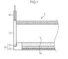
- an electric furnace 1 has at a predetermined position thereof a slag discharge outlet 1a through which slag is discharged from the electric furnace 1.
- Slag is a by-product resulting from oxidation of impurities contained in scraps in the electric furnace 1 during steelmaking.
- the slag isolates molten steel in the electric furnace 1 from the air, thus retaining arc-generating heat, and preventing the molten steel from adsorbing impurities contained in the air.
- a door 10 opens and closes the slag discharge outlet 1a to control discharge of slag.
- a door support 20 is provided in an end of the slag discharge outlet 1a. A portion of a lower end of the door 10 overlaps with the door support 20.
- a stepped portion 22 is formed at one side of the door support 20 so that the door support 20 has a depressed shape.
- the stepped portion 22 supports a lower surface of the lower end of the door 10.
- the door support 20 includes a support base portion 21 with which the lower end of the door 10 partially overlaps, and the stepped portion 22 which protrudes from one side of the support base portion 21 with a height difference between the stepped portion 22 and the support base portion 21, which provides a recessed portion and supports the lower end of the door 10.
- the door support 20 includes first coolant passages 23, which are located in the stepped portion 22 to cool an upper surface of the stepped portion 22, and second coolant passages 24 which cool the door support 20 to protect it from being deformed by high heat of slag.
- the cooling is performed by circulating cooling water through the first coolant passages 23 and the second coolant passages 24.
- the door support 20 is made of metal that is resistant to high heat.
- the door support 20 is cooled by the cooling water circulating through the second coolant passages 24 so that when slag is discharged out of the slag discharge outlet 1a, the door support 20 is protected from being deformed by high heat of the slag.
- cooling water flowing through the first coolant passages 23 cools the upper surface of the stepped portion 22 so that slag that leaks through a gap formed between the upper surface of the stepped portion 22 and the lower end of the door 10 is cooled and solidified.
- the door 10 has coolant passages 11 in the portion thereof that overlaps with the door support 20.
- Cooling water circulates through the coolant passages 11 to cool the lower end of the door 10 so that slag that leaks through the gap formed between the upper surface of the stepped portion 22 and the lower end of the door 10 is cooled and solidified.
- Slag that is formed on the surface of molten steel in the electric furnace 1 during steelmaking expands in volume during carburization in oxidation refining.
- the expanded slag is drawn into the slag discharge outlet 1a.
- the initial slag formed by expanding in volume during the oxidation refining process contains a large amount of valuable metal oxides, such as iron oxide (FeO) and is characterized by very high fluidity.
- metal oxides such as iron oxide (FeO)
- the door 10 closes the slag discharge outlet 1a to prevent the initial expanded slag from being discharged.
- the door 10 is configured so that the lower end thereof partially overlaps with the corresponding surface of the door support 20.
- the door 10 is configured in such a way that the lower end thereof overlaps the upper surface of the stepped portion 22, so that slag is additionally prevented from leaking.
- the lower end of the door 10 is seated and supported on the upper surface of the stepped portion 22 so that a gap between the door 10 and the stepped portion 22 is minimized.
- the fluidity of the initial slag is very high; sufficient to leak even through tiny gaps between the door 10 and the door support 20.
- the initial slag that is in the gap between the door 10 and the door support 20 is cooled and solidified by the cooling water that circulates through the coolant passages 11 and the first coolant passages 23.
- the gap between door 10 and the door support 20 is completely sealed by the solidified slag, so that slag is reliably prevented from leaking out of electric furnace 1 through the gap.
- the door 10 is operated by a door operator 30 to open or close the slag discharge outlet 1a of the electric furnace 1.
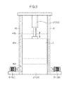
- the door operator 30 may comprise a door lift device 31 which moves the door 10 upwards or downwards to open or close the slag discharge outlet 1a.
- the door operator 30 may comprise a door rotating device which rotates the door 10 to open or close the slag discharge outlet 1a of the electric furnace 1, although it is not shown in the drawings.
- the door operator 30 may comprise a door sliding device which horizontally slides the door 10 to open or close the slag discharge outlet 1a of the electric furnace 1.
- a door sliding device which horizontally slides the door 10 to open or close the slag discharge outlet 1a of the electric furnace 1.
- the door lift device 31 comprises a hydraulic cylinder or pneumatic cylinder which is coupled to an upper end of the door 10.
- a piston rod of the hydraulic cylinder or pneumatic cylinder is coupled to the upper end of the door 10.
- the piston rod is actuated by controlling hydraulic pressure applied into the hydraulic cylinder, thus moving the door 10 upwards or downwards.
- the present invention further includes guide rails 40 which guide the door 10 when it moves to open or close the slag discharge outlet 1a.
- guide rails 40 are placed upright on opposite sides of the door 10.
- Guide grooves 40b are formed in respective guide rails 40 in the longitudinal directions thereof so that guide protrusions 40a provided on the respective opposite side edges of the door 10 are inserted into the corresponding guide grooves 40b.
- the guide grooves 40b are formed in the guide rails 40 in the same direction as the direction in which the door 10 moves.
- the guide protrusions 40a which are inserted into the corresponding guide grooves 40b are provided on the opposite side edges of the door 10.
- each guide protrusion 40a includes a groove cover protrusion 40c which extends a predetermined length from the door 10 downwards and is inserted in the corresponding guide groove 40b of the guide rail 40.
- the groove cover protrusions 40c of the guide protrusions 40a move with being placed in the corresponding guide grooves 40b to cover the guide grooves 40b that communicate with the slag discharge outlet 1a when the slag discharge outlet 1a is open.
- the groove cover protrusions 40c cover portions of the corresponding guide grooves 40b that are exposed by opening the slag discharge outlet 1a, and this prevent the slag from filling the guide grooves 40b.
- the embodiment may be modified in such a way that guide grooves 40b are formed on the opposite side edges of the door 10, and that guide protrusions 40a which are inserted into the corresponding guide grooves 40b are provided on the guide rails 40 that are placed upright on opposite sides of the door 10.
- Such a door guide structure can be modified into any structure which is disposed in the direction in which the door 10 moves, that is, in the direction in which the door 10 is operated to open or close the slag discharge outlet 1a, so long as it can correctly guide the movement of the door 10.
- coolant passages 41 are provided in each guide rail 40.
- Cooling water circulates through the coolant passages 41 to cool the guide rail 40.
- the guide rail 40 is cooled by the cooling water that circulates the coolant passages 41, thus the guide rail 40 is protected from being deformed by high heat of slag that is discharged from the electric furnace 1 through the slag discharge outlet 1a.
- the coolant passages 41 functions to solidify slag which is adhered to the guide rail 40 while slag is discharged through the slag discharge outlet 1a, and thus, it is easy to remove the adhered slag from the guide rail 40.
- the present invention further includes a solidified slag detaching unit 50 which detaches solidified slag from the upper surface of the door support 20.
- Solidified slag formed by solidification of slag on the upper surface of the door support 20 causes a problem of forming a gap between the door 10 and the door support 20 when the door 10 which has been open is closed. Hence, after the door 10 has been open, such solidified slag must be eliminated.
- the solidified slag while being solidified, is adhered to the upper surface of the door support 20, that is, the upper surface of the stepped portion and side surfaces of the door support 20. Thus, it is not easy for a worker to remove the base metal.
- the solidified slag detaching unit 50 is operated to detach the solidified slag from the upper surface of the door support 20, and thus makes it easy for the worker to eliminate the solidified base metal.
- the solidified slag detaching unit 50 may comprise a support vibrating motor 51 which is connected to the door support 20 and vibrates the door support 20.
- the support vibrating motor 51 vibrates the door support 20 to remove solidified slag on the upper surface of the door support 20 from the door support 20.
- the solidified slag detaching unit 50 includes a plurality of solidified slag removal protrusions 52 which are placed through the stepped portion 22 so as to be movable upwards and downwards and thus extracted from and retracted into the upper surface of the stepped portion 22, and a protrusion drive device 53 which moves the solidified slag removal protrusions 52 upwards and downwards.
- the protrusion drive device 53 may comprise a hydraulic cylinder.
- the structure of the protrusion drive device 53 can be variously modified as long as it can move the solidified slag removal protrusions 52 upwards and downwards.
- the solidified slag removal protrusions 52 are extracted upwards from the upper surface of the stepped portion 22 of the door support 20 by the operation of the protrusion drive device 53, that is, the hydraulic cylinder, thus detaching solidified slag from the upper surface of the stepped portion 22.
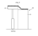
- a door support 20 may include a support base portion 21 with which the lower end of the door 10 partially overlaps, and a stepped portion 22 which is provided on a side surface of the support base portion 21 so as to be movable upwards and downwards and supports the lower end of the door 10.
- the solidified slag detaching unit 50 may include a stepped portion drive device 54 which moves the stepped portion 22 upwards and downwards.
- the stepped portion drive device 54 moves the stepped portion 22 upwards and downwards while the stepped portion 22 is in close contact with the side surface of the support base portion, so that solidified slag which has been adhered to the upper surface of the stepped portion 22 and solidified slag which has been adhered to the side surface of the support base portion 21 are detached therefrom by impacts generated when the stepped portion 22 moves upwards and downwards.
- the stepped portion drive device 54 is illustrated as comprising a hydraulic cylinder, any device can be used as the stepped portion drive device 54 so long as it can move the stepped portion 22 upwards and downwards.
- the stepped portion drive device 54 can moves the stepped portion 22 upwards to a height equal to or higher than the upper surface of the support base portion 21.
- the reason for this is to facilitate removal of solidified slag which is between the door 10 and the door support 20
- the solidified slag detaching unit 50 further includes an operation controller 55 which is connected to the door operator 30 and the stepped portion drive device 54 so that when the slag discharge outlet 1a is open or closed, the stepped portion 22 automatically moves upwards or downwards under the control of the operation controller 55.
- the operation controller 55 is operated in such a way that when the door 10 is lifted, the stepped portion 22 is moved upwards and, when the door 10 moves downwards, the stepped portion 22 is moved downwards.
- the operation controller 55 is operated such that when the slag discharge outlet 1a is open, the stepped portion 22 is level with the support base portion 21.
- the reason for this is to make it easy for the worker to conduct work of eliminating solidified slag when slag is solidified and to prevent slag from undesirably flowing outwards due to increased space between the door 10 and the stepped portion 22 when the slag discharge outlet 1a is open.
- the stepped portion 22 can be moved higher than the upper surface of the support base portion 21 so that removal of solidified slag (solidified slag) is facilitated.
- the worker can easily eliminate, using a tool, the solidified slag that is detached from the upper surface of the door support 20.
- the present invention further includes a solidified slag detaching unit 60 which removes solidified slag that has been adhered to the guide rail 40.
- the solidified slag detaching unit 60 detaches the solidified slag from the guide rail 40, thus making it easy for the worker to remove the solidified slag from the guide rail 40.
- the solidified slag detaching unit 60 may comprise a rail vibrating motor 61 which is connected to the guide rail 40 and vibrates the guide rail 40.
- the rail vibrating motor 61 vibrates the guide rail 40 so that slag solidified on the surface of the guide rail 40, that is, solidified slag formed on the guide rail 40, is detached from the guide rail 40.
- the solidified slag detaching unit 60 may include a plurality of solidified slag removal pins 62 which are movably placed through the guide rail 40, and a pin drive device 63 which moves the solidified slag removal pins 62 so that the solidified slag removal pins 62 protrude from a guide surface of the guide rail 40 which guides the door 10.
- the pin drive device 63 may comprise any other structure, so long as it can move the solidified slag removal pins 62 in the lateral direction.
- the solidified slag removal pins 62 are extracted from the guide surface of the guide rail 40; in other words, from the surface of the guide rail 40 that is connected to the door 10 to guide the movement of the door 10, by the operation of the pin drive device 63, that is, the hydraulic cylinder. Thereby, the solidified slag solidified on the guide surface of the guide rail 40 can be detached therefrom.
- the present invention prevents slag from leaking out of the electric furnace 1 through a gap formed between the door support 20 and the door 10 which opens or closes the slag discharge outlet 1a. Furthermore, solidified slag, that is, base metal, formed between the door 10 and the door support 20 can be easily removed so that the sealed state of the slag discharge outlet 1a can be reliably maintained while the door 10 is in the closed state.
Landscapes
- Engineering & Computer Science (AREA)
- Mechanical Engineering (AREA)
- General Engineering & Computer Science (AREA)
- Chemical & Material Sciences (AREA)
- Manufacturing & Machinery (AREA)
- Materials Engineering (AREA)
- Metallurgy (AREA)
- Organic Chemistry (AREA)
- Furnace Charging Or Discharging (AREA)
- Furnace Details (AREA)
- Vertical, Hearth, Or Arc Furnaces (AREA)
- Refinement Of Pig-Iron, Manufacture Of Cast Iron, And Steel Manufacture Other Than In Revolving Furnaces (AREA)
Applications Claiming Priority (2)
| Application Number | Priority Date | Filing Date | Title |
|---|---|---|---|
| KR1020090132882A KR101185211B1 (ko) | 2009-12-29 | 2009-12-29 | 전기로의 슬래그 배출 도어 장치 |
| PCT/KR2010/004137 WO2011081266A1 (ko) | 2009-12-29 | 2010-06-25 | 전기로의 슬래그 배출 도어 장치 |
Publications (2)
| Publication Number | Publication Date |
|---|---|
| EP2482018A1 true EP2482018A1 (de) | 2012-08-01 |
| EP2482018A4 EP2482018A4 (de) | 2015-11-11 |
Family
ID=44226657
Family Applications (1)
| Application Number | Title | Priority Date | Filing Date |
|---|---|---|---|
| EP10841099.4A Withdrawn EP2482018A4 (de) | 2009-12-29 | 2010-06-25 | Türvorrichtung zur abgabe von schlacke für einen elektroofen |
Country Status (6)
| Country | Link |
|---|---|
| US (1) | US8409494B2 (de) |
| EP (1) | EP2482018A4 (de) |
| JP (1) | JP2012529004A (de) |
| KR (1) | KR101185211B1 (de) |
| CN (1) | CN102472579B (de) |
| WO (1) | WO2011081266A1 (de) |
Cited By (16)
| Publication number | Priority date | Publication date | Assignee | Title |
|---|---|---|---|---|
| EP2762576A4 (de) * | 2011-09-30 | 2015-04-29 | Hyundai Steel Co | Verfahren zur herstellung einer schlammentladungsklappe |
| CN106196158A (zh) * | 2016-08-12 | 2016-12-07 | 桐乡市珂尼尔日用品有限公司 | 一种散热型燃烧机出渣炉门装置 |
| CN106196153A (zh) * | 2016-08-12 | 2016-12-07 | 莫焕东 | 一种可防护的燃烧机用出渣炉门装置 |
| CN106196155A (zh) * | 2016-08-12 | 2016-12-07 | 桐乡市珂尼尔日用品有限公司 | 一种升降速度可调的燃烧机出渣炉门装置 |
| CN106247391A (zh) * | 2016-08-12 | 2016-12-21 | 桐乡市珂尼尔日用品有限公司 | 一种燃烧机用安全出渣炉门装置 |
| CN106247390A (zh) * | 2016-08-12 | 2016-12-21 | 桐乡市珂尼尔日用品有限公司 | 一种降噪式燃烧机出渣炉门装置 |
| CN106247385A (zh) * | 2016-08-12 | 2016-12-21 | 桐乡市珂尼尔日用品有限公司 | 一种便于观察的燃烧机出渣炉门装置 |
| CN106247392A (zh) * | 2016-08-12 | 2016-12-21 | 桐乡市珂尼尔日用品有限公司 | 一种新式燃烧机用出渣炉门装置 |
| CN106247389A (zh) * | 2016-08-12 | 2016-12-21 | 桐乡市珂尼尔日用品有限公司 | 一种减震型燃烧机出渣炉门装置 |
| CN106287797A (zh) * | 2016-08-12 | 2017-01-04 | 桐乡市珂尼尔日用品有限公司 | 一种燃烧机出渣炉门控制系统 |
| CN106287800A (zh) * | 2016-08-12 | 2017-01-04 | 莫焕东 | 一种燃烧机出渣炉门装置 |
| CN106287795A (zh) * | 2016-08-12 | 2017-01-04 | 莫焕东 | 一种可调的燃烧机出渣炉门装置 |
| CN106287765A (zh) * | 2016-08-12 | 2017-01-04 | 桐乡市珂尼尔日用品有限公司 | 一种太阳能供电的燃烧机出渣炉门装置 |
| CN106287801A (zh) * | 2016-08-12 | 2017-01-04 | 桐乡市珂尼尔日用品有限公司 | 一种新型燃烧机出渣炉门装置 |
| CN106287798A (zh) * | 2016-08-12 | 2017-01-04 | 桐乡市珂尼尔日用品有限公司 | 一种安全燃烧机出渣炉门装置 |
| EP2647937A4 (de) * | 2010-11-29 | 2018-01-10 | Hyundai Steel Company | Türvorrichtung zur schlackeentladung für einen elektroofen |
Families Citing this family (24)
| Publication number | Priority date | Publication date | Assignee | Title |
|---|---|---|---|---|
| US7811665B2 (en) | 2008-02-29 | 2010-10-12 | The Procter & Gamble Compmany | Embossed fibrous structures |
| US8025966B2 (en) | 2008-02-29 | 2011-09-27 | The Procter & Gamble Company | Fibrous structures |
| US7960020B2 (en) | 2008-02-29 | 2011-06-14 | The Procter & Gamble Company | Embossed fibrous structures |
| US7687140B2 (en) | 2008-02-29 | 2010-03-30 | The Procter & Gamble Company | Fibrous structures |
| US8334049B2 (en) | 2010-02-04 | 2012-12-18 | The Procter & Gamble Company | Fibrous structures |
| US8334050B2 (en) | 2010-02-04 | 2012-12-18 | The Procter & Gamble Company | Fibrous structures |
| ITMI20120532A1 (it) * | 2012-04-02 | 2013-10-03 | Tenova Spa | Apparato di chiusura della porta di scorifica e di pulizia della porta e del canale di scorifica di un forno metallurgico e relativo metodo |
| CN106119675B (zh) * | 2016-08-11 | 2017-09-12 | 金堆城钼业股份有限公司 | 一种钼铁熔炼炉排渣装置及排渣方法 |
| CN106090992A (zh) * | 2016-08-12 | 2016-11-09 | 纪敏婵 | 一种燃烧机用新型出渣炉门装置 |
| CN106287792A (zh) * | 2016-08-12 | 2017-01-04 | 纪敏婵 | 一种燃烧机的便用出渣炉门装置 |
| CN106247383A (zh) * | 2016-08-12 | 2016-12-21 | 纪敏婵 | 一种带照明灯的燃烧机出渣炉门装置 |
| CN106196151A (zh) * | 2016-08-12 | 2016-12-07 | 纪敏婵 | 一种燃烧机用的可调出渣炉门装置 |
| CN106247381A (zh) * | 2016-08-12 | 2016-12-21 | 纪敏婵 | 一种节能型燃烧机出渣炉门装置 |
| CN106090991A (zh) * | 2016-08-12 | 2016-11-09 | 纪敏婵 | 一种便于观察且升降可调的燃烧机出渣炉门装置 |
| CN106247382A (zh) * | 2016-08-12 | 2016-12-21 | 纪敏婵 | 一种燃烧机的可散热出渣炉门装置 |
| CN106287793A (zh) * | 2016-08-12 | 2017-01-04 | 纪敏婵 | 一种炉门闭合报警的燃烧机出渣炉门装置 |
| CN106196152A (zh) * | 2016-08-12 | 2016-12-07 | 纪敏婵 | 一种燃烧机用防护出渣炉门装置 |
| CN106247384A (zh) * | 2016-08-12 | 2016-12-21 | 纪敏婵 | 一种太阳能供电调节升降的燃烧机出渣炉门装置 |
| CN106287794A (zh) * | 2016-08-12 | 2017-01-04 | 纪敏婵 | 一种能够闭合报警的燃烧机用可调出渣炉门装置 |
| CN106247380A (zh) * | 2016-08-12 | 2016-12-21 | 纪敏婵 | 一种可控燃烧机出渣炉门装置 |
| CN110777255B (zh) * | 2019-11-22 | 2025-01-24 | 中国恩菲工程技术有限公司 | 锌精矿流态化焙烧炉的排底料装置及锌精矿流态化焙烧炉 |
| CN111256478A (zh) * | 2020-03-23 | 2020-06-09 | 江苏新春兴再生资源有限责任公司 | 一种铅熔炼炉可控式放渣闸门装置及控制方法 |
| KR102736561B1 (ko) * | 2022-06-03 | 2024-12-02 | 현대제철 주식회사 | 전기로 |
| CN119755982B (zh) * | 2025-03-10 | 2025-06-13 | 浙江科奥高温技术集成有限公司 | 高温炉门板密封装置 |
Family Cites Families (12)
| Publication number | Priority date | Publication date | Assignee | Title |
|---|---|---|---|---|
| US2202362A (en) * | 1938-01-04 | 1940-05-28 | Alloy Steel And Metals Company | Electric melting furnace |
| US2772665A (en) * | 1949-03-19 | 1956-12-04 | Blaw Knox Co | Water cooled furnace structures |
| US2720192A (en) * | 1952-03-08 | 1955-10-11 | Humes George Walter | Water cooled furnace door and frame |
| US4483709A (en) * | 1972-03-27 | 1984-11-20 | Pennsylvania Engineering Corporation | Steel production method |
| JPH0333475A (ja) * | 1989-06-30 | 1991-02-13 | Hitachi Ltd | 燃料噴射制御装置 |
| JPH05346291A (ja) * | 1992-06-15 | 1993-12-27 | Toyohira Seiko Kk | 電気炉出滓堤付着地金及び付着スラグ除去装置 |
| FR2695715B1 (fr) * | 1992-09-11 | 1994-11-25 | Unimetall Sa | Porte de décrassage d'un four électrique à arc. |
| JPH07145420A (ja) * | 1993-09-30 | 1995-06-06 | Ishikawajima Harima Heavy Ind Co Ltd | 電気アーク溶解炉 |
| JP3867310B2 (ja) * | 1995-11-08 | 2007-01-10 | 石川島播磨重工業株式会社 | 製鋼用アーク炉の除滓口ドア装置 |
| JPH11211058A (ja) * | 1998-01-29 | 1999-08-06 | Nippon Steel Corp | 灰処理用電気溶融炉の出滓口構造 |
| US7767137B2 (en) * | 2006-06-20 | 2010-08-03 | Empco (Canada) Ltd. | Sealing apparatus for a slag door of a metallurgical furnace |
| IT1393096B1 (it) * | 2009-02-19 | 2012-04-11 | Sms Concast Italia Srl | Porta di scorifica in forno metallurgico ad arco costituito da un pannello mobile inferiore estrattore della scoria e da un pannello mobile superiore apribile per effettuare rilievi e interventi sul metallo fuso, e relativo apparato di comando |
-
2009
- 2009-12-29 KR KR1020090132882A patent/KR101185211B1/ko active Active
-
2010
- 2010-06-25 WO PCT/KR2010/004137 patent/WO2011081266A1/ko not_active Ceased
- 2010-06-25 CN CN201080024783.7A patent/CN102472579B/zh active Active
- 2010-06-25 EP EP10841099.4A patent/EP2482018A4/de not_active Withdrawn
- 2010-06-25 JP JP2012513887A patent/JP2012529004A/ja active Pending
-
2011
- 2011-12-05 US US13/311,424 patent/US8409494B2/en active Active
Non-Patent Citations (1)
| Title |
|---|
| See references of WO2011081266A1 * |
Cited By (16)
| Publication number | Priority date | Publication date | Assignee | Title |
|---|---|---|---|---|
| EP2647937A4 (de) * | 2010-11-29 | 2018-01-10 | Hyundai Steel Company | Türvorrichtung zur schlackeentladung für einen elektroofen |
| EP2762576A4 (de) * | 2011-09-30 | 2015-04-29 | Hyundai Steel Co | Verfahren zur herstellung einer schlammentladungsklappe |
| CN106247389A (zh) * | 2016-08-12 | 2016-12-21 | 桐乡市珂尼尔日用品有限公司 | 一种减震型燃烧机出渣炉门装置 |
| CN106287797A (zh) * | 2016-08-12 | 2017-01-04 | 桐乡市珂尼尔日用品有限公司 | 一种燃烧机出渣炉门控制系统 |
| CN106247391A (zh) * | 2016-08-12 | 2016-12-21 | 桐乡市珂尼尔日用品有限公司 | 一种燃烧机用安全出渣炉门装置 |
| CN106247390A (zh) * | 2016-08-12 | 2016-12-21 | 桐乡市珂尼尔日用品有限公司 | 一种降噪式燃烧机出渣炉门装置 |
| CN106247385A (zh) * | 2016-08-12 | 2016-12-21 | 桐乡市珂尼尔日用品有限公司 | 一种便于观察的燃烧机出渣炉门装置 |
| CN106247392A (zh) * | 2016-08-12 | 2016-12-21 | 桐乡市珂尼尔日用品有限公司 | 一种新式燃烧机用出渣炉门装置 |
| CN106196153A (zh) * | 2016-08-12 | 2016-12-07 | 莫焕东 | 一种可防护的燃烧机用出渣炉门装置 |
| CN106196155A (zh) * | 2016-08-12 | 2016-12-07 | 桐乡市珂尼尔日用品有限公司 | 一种升降速度可调的燃烧机出渣炉门装置 |
| CN106287800A (zh) * | 2016-08-12 | 2017-01-04 | 莫焕东 | 一种燃烧机出渣炉门装置 |
| CN106287795A (zh) * | 2016-08-12 | 2017-01-04 | 莫焕东 | 一种可调的燃烧机出渣炉门装置 |
| CN106287765A (zh) * | 2016-08-12 | 2017-01-04 | 桐乡市珂尼尔日用品有限公司 | 一种太阳能供电的燃烧机出渣炉门装置 |
| CN106287801A (zh) * | 2016-08-12 | 2017-01-04 | 桐乡市珂尼尔日用品有限公司 | 一种新型燃烧机出渣炉门装置 |
| CN106287798A (zh) * | 2016-08-12 | 2017-01-04 | 桐乡市珂尼尔日用品有限公司 | 一种安全燃烧机出渣炉门装置 |
| CN106196158A (zh) * | 2016-08-12 | 2016-12-07 | 桐乡市珂尼尔日用品有限公司 | 一种散热型燃烧机出渣炉门装置 |
Also Published As
| Publication number | Publication date |
|---|---|
| CN102472579B (zh) | 2014-08-27 |
| CN102472579A (zh) | 2012-05-23 |
| US8409494B2 (en) | 2013-04-02 |
| KR101185211B1 (ko) | 2012-09-21 |
| US20120139170A1 (en) | 2012-06-07 |
| WO2011081266A1 (ko) | 2011-07-07 |
| KR20110076231A (ko) | 2011-07-06 |
| JP2012529004A (ja) | 2012-11-15 |
| EP2482018A4 (de) | 2015-11-11 |
Similar Documents
| Publication | Publication Date | Title |
|---|---|---|
| EP2482018A1 (de) | Türvorrichtung zur abgabe von schlacke für einen elektroofen | |
| CN108300929B (zh) | 一种板材的加工方法及其连铸设备的进料机构 | |
| CN102027305B (zh) | 熔炉设备 | |
| EP3824235A1 (de) | Metallurgischer ofen mit integrierter abgashaube | |
| KR20120079053A (ko) | 전기로 | |
| EP2762576A2 (de) | Verfahren zur herstellung einer schlammentladungsklappe | |
| KR101225325B1 (ko) | 전기로의 슬래그 배출 도어 장치 | |
| KR101225260B1 (ko) | 전기로의 슬래그 배출 도어 구조체 | |
| JP2022126953A (ja) | 鋳造装置 | |
| KR101017113B1 (ko) | 탈산제 제조장치 | |
| KR20130107999A (ko) | 용탕이 잔존하지 않는 진공원심주조장치의 용탕투입구조 | |
| KR20130108000A (ko) | 레일을 통한 금형 교체식 진공원심주조장치 | |
| CN210877450U (zh) | 一种真空速凝甩带炉 | |
| KR102157597B1 (ko) | 용강 재산화 방지장치 | |
| KR102032655B1 (ko) | 전기로용 전극봉 냉각장치 | |
| KR20120050082A (ko) | 다이캐스팅장치 및 방법 | |
| KR20140042040A (ko) | 슬래그 환원 방법 | |
| KR101148914B1 (ko) | 용강 배출장치 | |
| KR101445090B1 (ko) | 노저 출선 전기로를 이용한 용융물을 드레인하는 방법 | |
| KR101607028B1 (ko) | 용탕 공급 장치용 스토퍼 | |
| KR102929601B1 (ko) | 실링재 회수장치 및 주조방법 | |
| JPH1129815A (ja) | アーク炉の装入材料予熱方法および装置 | |
| CN213624232U (zh) | 一种可滑动水冷式喂丝孔盖板 | |
| KR20120046828A (ko) | 압연기용 가열로 | |
| CN209520361U (zh) | 一种带复合结构扒渣头装置的扒渣机 |
Legal Events
| Date | Code | Title | Description |
|---|---|---|---|
| PUAI | Public reference made under article 153(3) epc to a published international application that has entered the european phase |
Free format text: ORIGINAL CODE: 0009012 |
|
| 17P | Request for examination filed |
Effective date: 20111202 |
|
| AK | Designated contracting states |
Kind code of ref document: A1 Designated state(s): AL AT BE BG CH CY CZ DE DK EE ES FI FR GB GR HR HU IE IS IT LI LT LU LV MC MK MT NL NO PL PT RO SE SI SK SM TR |
|
| DAX | Request for extension of the european patent (deleted) | ||
| RA4 | Supplementary search report drawn up and despatched (corrected) |
Effective date: 20151008 |
|
| RIC1 | Information provided on ipc code assigned before grant |
Ipc: F27D 1/18 20060101ALI20151002BHEP Ipc: F27D 3/15 20060101ALI20151002BHEP Ipc: C21C 5/52 20060101ALI20151002BHEP Ipc: F27B 3/19 20060101AFI20151002BHEP Ipc: F27B 3/10 20060101ALI20151002BHEP Ipc: F27B 3/08 20060101ALI20151002BHEP |
|
| STAA | Information on the status of an ep patent application or granted ep patent |
Free format text: STATUS: REQUEST FOR EXAMINATION WAS MADE |
|
| STAA | Information on the status of an ep patent application or granted ep patent |
Free format text: STATUS: THE APPLICATION IS DEEMED TO BE WITHDRAWN |
|
| 18D | Application deemed to be withdrawn |
Effective date: 20180103 |