EP2482356A2 - Rechteckiger akku mit einkerbug - Google Patents
Rechteckiger akku mit einkerbug Download PDFInfo
- Publication number
- EP2482356A2 EP2482356A2 EP10818987A EP10818987A EP2482356A2 EP 2482356 A2 EP2482356 A2 EP 2482356A2 EP 10818987 A EP10818987 A EP 10818987A EP 10818987 A EP10818987 A EP 10818987A EP 2482356 A2 EP2482356 A2 EP 2482356A2
- Authority
- EP
- European Patent Office
- Prior art keywords
- safety groove
- case body
- secondary battery
- case
- thickness
- Prior art date
- Legal status (The legal status is an assumption and is not a legal conclusion. Google has not performed a legal analysis and makes no representation as to the accuracy of the status listed.)
- Granted
Links
Images


Classifications
-
- H—ELECTRICITY
- H01—ELECTRIC ELEMENTS
- H01M—PROCESSES OR MEANS, e.g. BATTERIES, FOR THE DIRECT CONVERSION OF CHEMICAL ENERGY INTO ELECTRICAL ENERGY
- H01M50/00—Constructional details or processes of manufacture of the non-active parts of electrochemical cells other than fuel cells, e.g. hybrid cells
- H01M50/10—Primary casings; Jackets or wrappings
- H01M50/102—Primary casings; Jackets or wrappings characterised by their shape or physical structure
- H01M50/103—Primary casings; Jackets or wrappings characterised by their shape or physical structure prismatic or rectangular
-
- H—ELECTRICITY
- H01—ELECTRIC ELEMENTS
- H01M—PROCESSES OR MEANS, e.g. BATTERIES, FOR THE DIRECT CONVERSION OF CHEMICAL ENERGY INTO ELECTRICAL ENERGY
- H01M50/00—Constructional details or processes of manufacture of the non-active parts of electrochemical cells other than fuel cells, e.g. hybrid cells
- H01M50/10—Primary casings; Jackets or wrappings
- H01M50/116—Primary casings; Jackets or wrappings characterised by the material
- H01M50/117—Inorganic material
- H01M50/119—Metals
-
- H—ELECTRICITY
- H01—ELECTRIC ELEMENTS
- H01M—PROCESSES OR MEANS, e.g. BATTERIES, FOR THE DIRECT CONVERSION OF CHEMICAL ENERGY INTO ELECTRICAL ENERGY
- H01M50/00—Constructional details or processes of manufacture of the non-active parts of electrochemical cells other than fuel cells, e.g. hybrid cells
- H01M50/10—Primary casings; Jackets or wrappings
- H01M50/131—Primary casings; Jackets or wrappings characterised by physical properties, e.g. gas permeability, size or heat resistance
- H01M50/133—Thickness
-
- H—ELECTRICITY
- H01—ELECTRIC ELEMENTS
- H01M—PROCESSES OR MEANS, e.g. BATTERIES, FOR THE DIRECT CONVERSION OF CHEMICAL ENERGY INTO ELECTRICAL ENERGY
- H01M50/00—Constructional details or processes of manufacture of the non-active parts of electrochemical cells other than fuel cells, e.g. hybrid cells
- H01M50/30—Arrangements for facilitating escape of gases
- H01M50/342—Non-re-sealable arrangements
- H01M50/3425—Non-re-sealable arrangements in the form of rupturable membranes or weakened parts, e.g. pierced with the aid of a sharp member
-
- H—ELECTRICITY
- H01—ELECTRIC ELEMENTS
- H01M—PROCESSES OR MEANS, e.g. BATTERIES, FOR THE DIRECT CONVERSION OF CHEMICAL ENERGY INTO ELECTRICAL ENERGY
- H01M10/00—Secondary cells; Manufacture thereof
- H01M10/05—Accumulators with non-aqueous electrolyte
- H01M10/052—Li-accumulators
-
- Y—GENERAL TAGGING OF NEW TECHNOLOGICAL DEVELOPMENTS; GENERAL TAGGING OF CROSS-SECTIONAL TECHNOLOGIES SPANNING OVER SEVERAL SECTIONS OF THE IPC; TECHNICAL SUBJECTS COVERED BY FORMER USPC CROSS-REFERENCE ART COLLECTIONS [XRACs] AND DIGESTS
- Y02—TECHNOLOGIES OR APPLICATIONS FOR MITIGATION OR ADAPTATION AGAINST CLIMATE CHANGE
- Y02E—REDUCTION OF GREENHOUSE GAS [GHG] EMISSIONS, RELATED TO ENERGY GENERATION, TRANSMISSION OR DISTRIBUTION
- Y02E30/00—Energy generation of nuclear origin
-
- Y—GENERAL TAGGING OF NEW TECHNOLOGICAL DEVELOPMENTS; GENERAL TAGGING OF CROSS-SECTIONAL TECHNOLOGIES SPANNING OVER SEVERAL SECTIONS OF THE IPC; TECHNICAL SUBJECTS COVERED BY FORMER USPC CROSS-REFERENCE ART COLLECTIONS [XRACs] AND DIGESTS
- Y02—TECHNOLOGIES OR APPLICATIONS FOR MITIGATION OR ADAPTATION AGAINST CLIMATE CHANGE
- Y02E—REDUCTION OF GREENHOUSE GAS [GHG] EMISSIONS, RELATED TO ENERGY GENERATION, TRANSMISSION OR DISTRIBUTION
- Y02E60/00—Enabling technologies; Technologies with a potential or indirect contribution to GHG emissions mitigation
- Y02E60/10—Energy storage using batteries
Definitions
- the present invention relates to a prismatic secondary battery having a safety groove, and, more particularly, to a prismatic secondary battery including an electrode assembly mounted in a prismatic battery case in a sealed state, the battery case including a hexahedral case body open at the top thereof, the hexahedral case body being made of a metal material, and a cap coupled to the open top of the body, the case cap having an electrode terminal, wherein the case body has a thickness of 0.4 mm or less, the case body is provided at a region exhibiting a stress distribution equivalent to 40 % or less of the maximum stress (S MAX ) of the case in a high pressure state with a line-shaped safety groove configured to be ruptured when high pressure occurs in the battery, and the safety groove is configured in a structure in which a residual thickness ('a vent thickness') of the case body is decreased toward the middle from opposite ends of the safety groove in the longitudinal direction.
- S MAX maximum stress
- a secondary battery may be classified as a cylindrical battery having an electrode assembly mounted in a cylindrical metal container, a prismatic battery having an electrode assembly mounted in a prismatic metal container, or a pouch-shaped battery having an electrode assembly mounted in a pouch-shaped case formed of an aluminum laminate sheet.
- the electrode assembly mounted in the battery case is a power generating element, having a cathode/separator/anode stack structure, which can be charged and discharged.
- the electrode assembly may be classified as a jelly roll type electrode assembly configured in a structure in which a long sheet type cathode and a long sheet type anode, to which active materials are applied, are wound while a separator is disposed between the cathode and the anode or a stacked type electrode assembly configured in a structure in which pluralities of cathodes and anodes having a predetermined size are sequentially stacked while separators are disposed respectively between the cathodes and the anodes.
- Secondary batteries may be exposed to various environments according to use status and conditions. It is necessary to prevent explosion of the secondary batteries for the sake of safety of users. Generally, the batteries may explode due to high temperature and high pressure in the batteries caused by an abnormal operational status, such as an internal short circuit, charging exceeding allowable current and voltage, exposure to high temperature, impact due to falling, of the batteries. For these reasons, each of the batteries is provided with a high pressure solving device for solving high pressure of the battery, which is a direct cause for battery explosion, although the shapes of the batteries are different from one another.
- a cylindrical battery has a safety plate of a specific structure, which is mounted to a cap assembly, a prismatic battery has a safety groove formed at a cap or a case of the battery, and a pouch-shaped battery is configured such that sutured portions (sealed portions) of laminate sheets are separated from each other without use of an additional safety groove.
- closed type or a partially open type safety groove is formed at an aluminum battery case such that the safety groove can be cut out.
- a prismatic secondary battery has a partially open type safety groove formed at the side of a battery case.
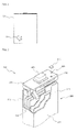
- a safety groove 30 of FIG. 1 is formed at a corner of the side of a case 20 of a prismatic secondary battery in the shape of a small contour.
- the safety groove is of a partially open type. That is, the safety groove is located at a region of the case exhibiting relatively high stress such that the curved safety groove can be ruptured when the internal pressure of the battery is excessively increased.
- the safety groove having the structure as described above has an advantage in that the safety groove can relatively sensitively respond to high pressure generated in the battery; however, the safety groove has a disadvantage in that it is difficult to correctly set an intended critical pressure value intended during designing of the battery.
- the present invention has been made to solve the above problems, and other technical problems that have yet to be resolved.
- the inventors of the present invention have found that, when a safety groove of a specific structure as well as a specific shape is formed at a region of the side of a case of a battery exhibiting relatively low stress, the safety groove is reliably rupture in a proper condition, thereby improving safety of the battery.
- a prismatic secondary battery including an electrode assembly consisting of a cathode, an anode, and a separator mounted in a prismatic battery case in a sealed state
- the battery case including a hexahedral case body open at the top thereof, the hexahedral case body being made of a metal material, and a case cap coupled to the open top of the case body, the case cap having an electrode terminal, wherein the case body has a thickness of 0.4 mm or less, the case body is provided at a region exhibiting a stress distribution equivalent to 40 % or less of the maximum stress (S MAX ) of the case in a high pressure state with a line-shaped safety groove configured to be ruptured when high pressure occurs in the battery, and the safety groove is configured in a structure in which a residual thickness ('a vent thickness') of the case body is decreased toward the middle from opposite ends of the safety groove in the longitudinal direction.
- S MAX maximum stress
- the safety groove of the prismatic battery according to the present invention is formed at a region of the case body exhibiting a stress distribution equivalent to 40 % or less of the maximum stress of the case, i.e., relatively low stress. Consequently, it is possible to prevent the safety groove from being easily ruptured at low pressure, to provide high rupture pressure, and to deeply form the safety groove.
- the prismatic battery according to the present invention is configured in a structure in which the safety groove is formed at a specific position such that the depth of the safety groove is decreased toward the middle from the opposite ends of the safety groove in the longitudinal direction, as supported from experiment examples, which will be described later. Consequently, the safety groove provides high operational reliability of the battery, and gas is quickly discharged from the battery through uniform rupture of the safety groove, thereby securing safety of the battery.
- the case body, to which the present invention is applied preferably has a thickness of 0.2 to 0.4 mm. Consequently, the safety groove located at the specific position and formed in the specific shape is reliably ruptured at a proper critical value although the thickness of the battery case according to the present invention is much less than that of a general battery case.
- the line-shaped safety groove is formed at a region of the case body exhibiting a stress distribution equivalent to 40 % of less of the maximum stress (S MAX ) of the case in the high pressure state as described above
- the stress distribution may be variously changed depending upon the shape and structure of the battery case.
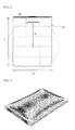
- a stress distribution generated in a general prismatic battery is shown in FIG. 4 .
- the inventors have found that, when the safety groove is formed at a region of the case body exhibiting a stress distribution equivalent to more than 40 % of the maximum stress (S MAX ) of the case, the safety groove is easily ruptured even at low pressure.
- the safety groove is ruptured at higher pressure when the above conditions are satisfied than when the safety groove is formed at a region of the case body exhibiting a conventional high stress distribution, i.e., a stress distribution equivalent to more than 40 % of the maximum stress (S MAX ) of the case.
- the safety groove may be formed at a region of the case body exhibiting a stress distribution equivalent to preferably 10 to 40 %, more preferably 25 to 35 %, of the maximum stress (S MAX ) of the case.
- the safety groove is formed at the region of the case body exhibiting relatively low stress, therefore, it is possible to prevent the safety groove from being easily ruptured at low pressure, to provide high rupture pressure, and to deeply form the safety groove.
- the safety groove is formed at a vertical center axis region of each main surface of the case body. More preferably, the safety groove is formed at a middle position having a size equivalent to 1/4 to 1/2 of the lateral width of the case body and at an upper or lower position having a size equivalent to 1/20 to 1/5 of the vertical length of the case body.
- the safety groove according to the present invention is formed in an arc shape to prevent discharge of gas from being disproportionately concentrated on a portion of the safety groove, thereby minimizing pressure deviation upon rupture of the safety groove and securing strength of the case with respect to the thin case body.
- the safety groove may be formed in an upward arc shape in which the center of curvature of the arc shape is located at the upside or in a downward arc shape in which the center of curvature of the arc shape is located at the downside.
- the inventors have experimentally confirmed that, when the vent thickness of the safety groove was uniform, the safety groove was not effectively ruptured although the safety groove was formed at a region of the case body exhibiting relatively low stress in an arc shape.
- the vent thickness may have an average value equivalent to 40 to 70 % of the thickness of the case body. That is, the average value of the vent thickness may be decided within a range which can provide an optimum state in consideration of various factors as previously described.
- vent thickness may be successively decreased toward the middle from the opposite ends of the safety groove.
- “successively decreased” means “gradually decreased.” Consequently, concentration of pressure on a specific region is prevented, and pressure deviation upon rupture of the safety groove is minimized.
- vent thickness at the middle of the safety groove is not particularly restricted as long as the vent thickness at the middle of the safety groove is less than the vent thickness at the opposite ends of the safety groove with the result that the safety groove can be easily ruptured.
- the vent thickness at the middle of the safety groove has a size equivalent to 40 to 70 % of the vent thickness at the opposite ends of the safety groove.
- the prismatic battery having the safety grove configured such that the vent thickness is decreased toward the middle from the opposite ends of the safety groove exhibited effective operational reliability.
- the safety groove may be formed using various methods.
- the safety groove is formed through rolling using an additional punch. According to circumstances, it is possible to scrape the case using a specific tool to form the safety groove.
- the vertical section of the safety groove is not particularly restricted as long as the safety groove can be easily ruptured when the internal pressure of the battery is increased.
- the vertical section of the safety groove may be formed in a downward wedge shape or in a trapezoidal shape.
- the upside of the safety groove is cracked, with the result that the safety groove is ruptured.
- the trapezoidal shape short sides of the safety groove are lengthened, with the result that the safety groove is ruptured due to shear stress. In conclusion, uniform and immediate rupture of the safety groove are induced, thereby securing safety of the battery.
- the electrode assembly may be configured in a jelly-roll (winding type) structure in which a long sheet type cathode and anode are wound while a separator is disposed between the cathode and the anode, which has an advantage in that the jelly-roll is easily manufactured and has high energy density per weight.
- a jelly-roll winding type
- the secondary battery includes a lithium secondary battery.
- the prismatic secondary battery according to the present invention is configured in a structure in which a safety groove is formed at a specific region exhibiting relatively low stress in an arc shape such that the thickness of a vent of the safety groove is gradually decreased toward the middle of the safety groove over the overall length of the safety groove, with the result that the safety groove is reliably ruptured at relatively high internal pressure of the battery to effectively discharge high-pressure gas from the battery. Consequently, it is possible to greatly improve safety of the battery.
- a prismatic secondary battery 100 includes an electrode assembly 300, which is configured in a jelly-roll structure in which a sheet type cathode and a sheet type anode are wound while a separator is disposed between the cathode and the anode, is mounted in a prismatic battery case 200, which serves as an anode terminal.
- the case 200 includes a hexahedral case body 210 open at the top thereof, the hexahedral case body 210 being made of metal, and a cap 220 coupled to the open top of the case body 210, the cap 220 having a cathode terminal 400.
- the anode terminal may be the case body 210 or the cap 220 electrically insulated from the cathode terminal 400.
- the electrode assembly 300 is placed in the case body 210, the cap 220 is located at the open top of the case body 210, and a connection region between the case body 210 and the cap 220 is sealed by laser welding. Subsequently, an electrolyte is injected into the case 200. Electrolyte injection is performed through an injection port 230 formed at a one-side region of the cap 220. Specifically, the electrolyte is injected into the case 200 through the injection port 230, a ball member 600 made of aluminum is fitted into the injection port 230, and a thin metal sheet 610 is placed on the ball member 600 to close the injection port 230. In this state, the injection port 230 is sealed by laser welding. Sealing of the injection port 230 is not limited to the above method. Various other methods may be used to seal the injection port 230.
- a safety groove according to the present invention is formed at a front side 211 or a rear side 212 of the case 200 of the prismatic secondary battery 100.
- the case body 210 has a thickness of approximately 0.3 mm.
- FIG. 3 is a plan view illustrating the shape of a safety groove according to an embodiment of the present invention
- FIG. 4 is a photograph illustrating stress distribution of the prismatic secondary battery of FIG. 3 .
- a safety groove 60 formed at a case body 40 is a member that can be cut out to discharge high-pressure gas.
- the safety groove 60 is formed at a region of a case exhibiting a stress distribution equivalent to approximately 25 to 35 % of the maximum stress S MAX of the case in an upward arc shape in which the center of curvature of an arc shape is located at the upside.
- stress distribution is shown in the form of a contour line of tensile stress per region occurring upon application of predetermined pressure.
- a high brightness region (a bright region) has relatively high stress. In other words, the high brightness region is a region where maximum stress S MAX is distributed.
- a low brightness region (a dark region) has relatively low stress. In other words, the low brightness region is a region where minimum stress S MIN is distributed.
- the arc-shaped safety groove 60 is formed at a middle position having a size equivalent to approximately 1/3 of the width W of the case body 40 and at an upper end position having a size equivalent to approximately 1/10 of the length L of the case body 40. Also, the arc shape of the safety groove 60 has a radius R of curvature equivalent to approximately 1/2 of the length L of the case body 40. Because of such an arc shape, it is possible for the safety groove 60 to maintain uniform mechanical strength while achieving uniform-discharge of gas.
- the arc shape is formed such that the center of curvature of the arc shape is located at the upside.
- the arc shape may be formed such that the center of curvature of the arc shape is located at the downside.
- the safety groove of FIG. 5 is identical in position and curvature to the safety groove of FIG. 3 except that the arc shape of the safety groove of FIG. 5 is formed such that the center of curvature of the arc shape is located at the downside, and therefore, a detailed description thereof will not be given.
- FIG. 6 is a partial plan view illustrating the shape of the safety groove
- FIG. 7 is a graph illustrating a thickness per vent region of the safety groove of FIG. 6
- FIG. 8 is a photograph illustrating a vertical section of the safety groove of FIG. 3 .
- the thickness of a vent 80 is gradually decreased from opposite ends 1 and 5 to the middle 3 of the safety groove over the entire length 1 of the safety groove. That is, the thickness t of the vent at the middle 3 of the safety groove 60 (see Example 1) is approximately 58 ⁇ m, which is the minimum, with respect to the thickness T of the case body. At predetermined positions approaching the opposite ends of the safety groove, the vent has thicknesses t of approximately 70 ⁇ m and approximately 90 ⁇ m, respectively. That is, the thickness t of the vent is gradually increased toward the opposite ends of the safety groove.
- the vertical section of the safety groove 60 is formed in a downward wedge shape, and the average thickness of the vent is approximately 60 % of the thickness T of the case body 40.
- a cathode active material containing LiCoO 2 was applied to an aluminum current collector, and then a cathode tab was attached to the end of the current collector, such that the cathode tab protruded upward, by spot welding, to manufacture a cathode.
- An anode active material containing artificial graphite was applied to a copper current collector, an anode tab was attached to the end of the current collector, such that the anode tab protruded upward, by spot welding, and a polyimide film was wound at the interface between the current collector and the anode tab so as to surround the front, the rear, and one side of the anode tab such that the polyimide film protruded 5 to 6 mm from the upper end of the current collector to manufacture an anode.
- a safety groove was formed at an aluminum prismatic case having a thickness of approximately 250 to 270 ⁇ m in the vertical sectional shape of a wedge using a punch such that the safety groove was located at a position having a size equivalent to approximately 1/3 of the width of a case body and at a position having a size equivalent to approximately 1/10 of the length of the case body and such that such that the safety groove had a radius of curvature equivalent to approximately 1/2 of the length of the case body.
- the safety groove was formed such that a vent had a thickness of approximately 57 ⁇ m at the middle of the safety groove and such that the vent had thicknesses of approximately 70 ⁇ m and approximately 90 ⁇ m, respectively, at predetermined positions approaching opposite ends of the safety groove, i.e., such that the thickness of the vent was gradually increased toward the opposite ends of the safety groove (see Example 1 of FIG. 7 ). It was confirmed that the safety groove was formed at a region of the case exhibiting a stress distribution equivalent to approximately 25 to 35 % of the maximum stress S MAX of the case.
- the cathode manufactured as described in Section 1-1 and the anode manufactured as described in Section 1-2 were wound into a roll and compressed while a separator was disposed between the cathode and the anode to manufacture a prismatic jelly-roll.
- the prismatic jelly-roll was placed in the aluminum prismatic case having the safety groove formed as described in Section 1-3, and an EC-EMC blending-based solution was impregnated as an electrolyte to manufacture a battery.
- a battery was manufactured in the same manner as Example 1 except that a safety groove was formed such that a vent had a thickness of approximately 49 ⁇ m at the middle of the safety groove and such that the vent had thicknesses of approximately 55 ⁇ m and approximately 75 ⁇ m, respectively, at predetermined positions approaching opposite ends of the safety groove, i.e., such that the thickness of the vent was gradually increased toward the opposite ends of the safety groove, as shown in Example 2 of FIG. 7 .
- a battery was manufactured in the same manner as Example 1 except that a safety groove was formed such that a vent had a thickness of approximately 40 ⁇ m at the middle of the safety groove and such that the vent had thicknesses of approximately 45 ⁇ m and approximately 63 ⁇ m, respectively, at predetermined positions approaching opposite ends of the safety groove, i.e., such that the thickness of the vent was gradually increased toward the opposite ends of the safety groove, as shown in Example 3 of FIG. 7 .
- a battery was manufactured in the same manner as Example 1 except that a safety groove was formed at a corner region of a case as shown in FIG. 1 , and a vent had a uniform thickness as shown in FIG. 9 .
- the straight distance h between opposite ends of the safety groove of FIG. 1 is approximately 16 mm.
- a battery was manufactured in the same manner as Example 1 except that a safety groove was formed at a top region of a case as shown in FIG. 3 , and a vent had a uniform thickness, as shown in FIG. 9 .
- the batteries of Examples 1 to 3 each of which had the arc-shaped safety groove formed at the specific region having low stress such that the thickness of the vent was gradually decreased toward the middle from the opposite ends of the safety groove, had rupture pressures of 12.4, 10.9, and 7.7 kgf/cm 2 , which were relatively high.
- the safety grooves of the batteries of Comparative example 2 each of which was formed at the same position as in Examples 1 to 3 and had the thickness of the vent similar to that of Example 2 and uniform in the longitudinal direction, were ruptured even at a pressure lower than those of the batteries of Example 2 as well as Example 3 although the thickness of the vent of each of the safety grooves of the batteries of Comparative example 2 was greater than the thickness of the vent of each of the safety grooves of the batteries of Example 3.
- the batteries of Examples 1 to 3 had average rupture times, 5 minutes, 4 minutes 37 seconds, and 4 minutes 14 seconds, which were relatively long.
- the safety grooves of the batteries of Comparative example 1 were easily ruptured in relatively short times.
- a battery having a safety groove according to the present invention is not easily ruptured at a middle or low pressure, at which the rupture of the battery is not allowed, thereby preventing injury due to leakage of an electrolyte and evaporated gas.
Landscapes
- Chemical & Material Sciences (AREA)
- Chemical Kinetics & Catalysis (AREA)
- Electrochemistry (AREA)
- General Chemical & Material Sciences (AREA)
- Inorganic Chemistry (AREA)
- Gas Exhaust Devices For Batteries (AREA)
- Sealing Battery Cases Or Jackets (AREA)
Applications Claiming Priority (2)
| Application Number | Priority Date | Filing Date | Title |
|---|---|---|---|
| KR20090090396 | 2009-09-24 | ||
| PCT/KR2010/006255 WO2011037346A2 (ko) | 2009-09-24 | 2010-09-14 | 노치홈이 구비된 각형 이차전지 |
Publications (3)
| Publication Number | Publication Date |
|---|---|
| EP2482356A2 true EP2482356A2 (de) | 2012-08-01 |
| EP2482356A4 EP2482356A4 (de) | 2014-04-16 |
| EP2482356B1 EP2482356B1 (de) | 2016-04-20 |
Family
ID=43796341
Family Applications (1)
| Application Number | Title | Priority Date | Filing Date |
|---|---|---|---|
| EP10818987.9A Active EP2482356B1 (de) | 2009-09-24 | 2010-09-14 | Prismatischer akku mit einer sicherheitskerbe |
Country Status (7)
| Country | Link |
|---|---|
| US (1) | US8974936B2 (de) |
| EP (1) | EP2482356B1 (de) |
| JP (1) | JP5674165B2 (de) |
| KR (1) | KR101183529B1 (de) |
| CN (1) | CN102576826B (de) |
| TW (1) | TWI426639B (de) |
| WO (1) | WO2011037346A2 (de) |
Cited By (3)
| Publication number | Priority date | Publication date | Assignee | Title |
|---|---|---|---|---|
| WO2017171459A1 (ko) * | 2016-03-31 | 2017-10-05 | 주식회사 엘지화학 | 고 유연성의 전극조립체 및 이를 포함하는 전지셀 |
| EP3694013A4 (de) * | 2018-12-29 | 2020-10-21 | Contemporary Amperex Technology Co., Limited | Sekundärbatterie und batteriemodul |
| US11316189B2 (en) | 2013-10-22 | 2022-04-26 | Semiconductor Energy Laboratory Co., Ltd. | Secondary battery and electronic device |
Families Citing this family (12)
| Publication number | Priority date | Publication date | Assignee | Title |
|---|---|---|---|---|
| JP2012014978A (ja) * | 2010-07-01 | 2012-01-19 | Nisshin Steel Co Ltd | 電池用ケースの安全弁 |
| JP5938249B2 (ja) * | 2012-03-27 | 2016-06-22 | 本田技研工業株式会社 | 電動式鞍乗り型車両のバッテリユニット |
| KR20140015769A (ko) * | 2012-07-24 | 2014-02-07 | 삼성에스디아이 주식회사 | 이차 전지 |
| KR102052063B1 (ko) * | 2013-01-11 | 2019-12-04 | 삼성에스디아이 주식회사 | 이차 전지 |
| JP5574003B1 (ja) * | 2013-03-29 | 2014-08-20 | 株式会社豊田自動織機 | 蓄電装置 |
| US9583741B2 (en) * | 2013-07-05 | 2017-02-28 | Samsung Sdi Co., Ltd. | Secondary battery |
| JP6536354B2 (ja) * | 2015-11-02 | 2019-07-03 | 株式会社村田製作所 | 電池、電池パック、電子機器、電動車両、蓄電装置および電力システム |
| KR102629177B1 (ko) * | 2016-07-12 | 2024-01-26 | 삼성에스디아이 주식회사 | 이차 전지 |
| US9837682B1 (en) * | 2016-08-29 | 2017-12-05 | Microsoft Technology Licensing, Llc | Variable layer thickness in curved battery cell |
| JP7782448B2 (ja) * | 2020-08-24 | 2025-12-09 | 株式会社Gsユアサ | 蓄電素子 |
| CA3193858A1 (en) * | 2021-09-28 | 2023-03-28 | Mingguang GU | Pressure relief apparatus, battery cell, battery, and electrical device |
| US12107285B2 (en) * | 2022-01-13 | 2024-10-01 | GM Global Technology Operations LLC | Systems and methods for responding to thermal excursions in a battery |
Family Cites Families (20)
| Publication number | Priority date | Publication date | Assignee | Title |
|---|---|---|---|---|
| KR100422175B1 (ko) | 1997-01-13 | 2004-03-10 | 오보닉 배터리 컴퍼니, 아이엔씨. | 유체 냉각 배터리 팩 시스템 |
| KR100329562B1 (ko) * | 1999-07-05 | 2002-03-20 | 김순택 | 이차전지 |
| JP2001126693A (ja) * | 1999-10-25 | 2001-05-11 | Nec Mobile Energy Kk | 密閉型電池 |
| JP3863351B2 (ja) * | 2000-02-18 | 2006-12-27 | 松下電器産業株式会社 | 角形電池および角形電池の安全機構の製造方法 |
| JP2001266804A (ja) * | 2000-03-23 | 2001-09-28 | At Battery:Kk | 密閉二次電池 |
| WO2002027819A1 (en) * | 2000-09-29 | 2002-04-04 | Lg Chemical Co., Ltd. | Safety plate of secondary battery |
| JP4155734B2 (ja) * | 2001-12-20 | 2008-09-24 | 三洋電機株式会社 | 電池の安全弁 |
| JP4100978B2 (ja) * | 2002-06-28 | 2008-06-11 | 三洋電機株式会社 | 開裂溝付き密閉型電池 |
| JP4097482B2 (ja) * | 2002-08-19 | 2008-06-11 | 三洋電機株式会社 | 開裂溝付き密閉型電池 |
| KR20050037689A (ko) * | 2003-10-20 | 2005-04-25 | 삼성에스디아이 주식회사 | 최적 위치의 벤트를 갖는 이차전지 |
| CN2757343Y (zh) * | 2004-11-16 | 2006-02-08 | 比亚迪股份有限公司 | 一种防爆安全电池 |
| KR101136162B1 (ko) * | 2005-09-06 | 2012-04-17 | 삼성에스디아이 주식회사 | 이차 전지 |
| KR101136215B1 (ko) * | 2005-09-06 | 2012-04-17 | 삼성에스디아이 주식회사 | 이차 전지 |
| KR100788574B1 (ko) * | 2005-11-29 | 2007-12-26 | 삼성에스디아이 주식회사 | 이차전지 |
| CN100468828C (zh) * | 2005-12-20 | 2009-03-11 | 深圳华粤宝电池有限公司 | 一种电池防爆铝壳及其铝壳防爆电池 |
| KR100824878B1 (ko) * | 2006-09-15 | 2008-04-23 | 삼성에스디아이 주식회사 | 이차전지 |
| JP5137480B2 (ja) | 2007-06-29 | 2013-02-06 | 三洋電機株式会社 | 車両用の電源装置 |
| US20090068548A1 (en) * | 2007-09-06 | 2009-03-12 | Gillettte Company, The | Lithium Ion Prismatic Cells |
| KR100922470B1 (ko) * | 2007-09-14 | 2009-10-21 | 삼성에스디아이 주식회사 | 이차 전지 |
| JP2009147187A (ja) | 2007-12-17 | 2009-07-02 | Calsonic Kansei Corp | 発熱体の冷却装置 |
-
2010
- 2010-09-14 JP JP2012530769A patent/JP5674165B2/ja active Active
- 2010-09-14 KR KR1020100089898A patent/KR101183529B1/ko active Active
- 2010-09-14 WO PCT/KR2010/006255 patent/WO2011037346A2/ko not_active Ceased
- 2010-09-14 CN CN201080042832.XA patent/CN102576826B/zh active Active
- 2010-09-14 EP EP10818987.9A patent/EP2482356B1/de active Active
- 2010-09-20 TW TW099131799A patent/TWI426639B/zh active
-
2011
- 2011-11-29 US US13/306,677 patent/US8974936B2/en active Active
Cited By (7)
| Publication number | Priority date | Publication date | Assignee | Title |
|---|---|---|---|---|
| US11316189B2 (en) | 2013-10-22 | 2022-04-26 | Semiconductor Energy Laboratory Co., Ltd. | Secondary battery and electronic device |
| US11677095B2 (en) | 2013-10-22 | 2023-06-13 | Semiconductor Energy Laboratory Co., Ltd. | Secondary battery and electronic device |
| US12388110B2 (en) | 2013-10-22 | 2025-08-12 | Semiconductor Energy Laboratory Co., Ltd. | Secondary battery and electronic device |
| WO2017171459A1 (ko) * | 2016-03-31 | 2017-10-05 | 주식회사 엘지화학 | 고 유연성의 전극조립체 및 이를 포함하는 전지셀 |
| US12002922B2 (en) | 2016-03-31 | 2024-06-04 | Lg Energy Solution, Ltd. | Electrode assembly having high flexibility and battery cell including the same |
| EP3694013A4 (de) * | 2018-12-29 | 2020-10-21 | Contemporary Amperex Technology Co., Limited | Sekundärbatterie und batteriemodul |
| US12244025B2 (en) | 2018-12-29 | 2025-03-04 | Contemporary Amperex Technology (Hong Kong) Limited | Secondary battery and battery module |
Also Published As
| Publication number | Publication date |
|---|---|
| US20120177961A1 (en) | 2012-07-12 |
| CN102576826B (zh) | 2014-11-19 |
| TW201140910A (en) | 2011-11-16 |
| CN102576826A (zh) | 2012-07-11 |
| JP2013506248A (ja) | 2013-02-21 |
| TWI426639B (zh) | 2014-02-11 |
| WO2011037346A3 (ko) | 2011-07-14 |
| EP2482356B1 (de) | 2016-04-20 |
| JP5674165B2 (ja) | 2015-02-25 |
| US8974936B2 (en) | 2015-03-10 |
| KR101183529B1 (ko) | 2012-09-20 |
| WO2011037346A2 (ko) | 2011-03-31 |
| EP2482356A4 (de) | 2014-04-16 |
| KR20110033038A (ko) | 2011-03-30 |
Similar Documents
| Publication | Publication Date | Title |
|---|---|---|
| EP2482356A2 (de) | Rechteckiger akku mit einkerbug | |
| EP2337110B1 (de) | Kappenanordnung mit erhöhter stabilität und zylinderförmige sekundärbatterie damit | |
| US8968898B2 (en) | Cap assembly of novel structure and cylindrical battery employed with the same | |
| US8277970B2 (en) | Pouch-type secondary battery having an non-sealing residue portion | |
| US10490792B2 (en) | Cap assembly for secondary battery | |
| TWI415319B (zh) | 柱狀二次電池之蓋組及包含該蓋組之柱狀二次電池 | |
| US20080070097A1 (en) | Secondary battery | |
| KR101347715B1 (ko) | 안전판이 구비된 각형 이차전지 | |
| KR101325030B1 (ko) | 안전판이 구비된 각형 이차전지 | |
| KR101516649B1 (ko) | 안전판이 구비된 각형 이차전지 | |
| KR20120094693A (ko) | 안전판이 구비된 각형 이차전지 | |
| KR200244258Y1 (ko) | 이차전지의 안전판 | |
| KR100788574B1 (ko) | 이차전지 | |
| KR20160034884A (ko) | 안전판이 구비된 각형 이차전지 | |
| KR101084919B1 (ko) | 이차전지 | |
| KR101254830B1 (ko) | 각형 이차전지 | |
| KR20120094194A (ko) | 안전판이 구비된 각형 이차전지 | |
| KR101326186B1 (ko) | 안전판이 구비된 각형 이차전지 | |
| KR100788555B1 (ko) | 이차전지 | |
| KR20140042837A (ko) | 안전판이 구비된 각형 이차전지 | |
| KR20140041662A (ko) | 안전판이 구비된 각형 이차전지 | |
| KR20140031348A (ko) | 안전판이 구비된 각형 이차전지 | |
| KR20140060881A (ko) | 용접 벤팅부가 구비된 각형 이차전지 |
Legal Events
| Date | Code | Title | Description |
|---|---|---|---|
| PUAI | Public reference made under article 153(3) epc to a published international application that has entered the european phase |
Free format text: ORIGINAL CODE: 0009012 |
|
| 17P | Request for examination filed |
Effective date: 20120322 |
|
| AK | Designated contracting states |
Kind code of ref document: A2 Designated state(s): AL AT BE BG CH CY CZ DE DK EE ES FI FR GB GR HR HU IE IS IT LI LT LU LV MC MK MT NL NO PL PT RO SE SI SK SM TR |
|
| DAX | Request for extension of the european patent (deleted) | ||
| A4 | Supplementary search report drawn up and despatched |
Effective date: 20140319 |
|
| RIC1 | Information provided on ipc code assigned before grant |
Ipc: H01M 2/12 20060101ALI20140313BHEP Ipc: H01M 10/052 20100101ALN20140313BHEP Ipc: H01M 2/02 20060101AFI20140313BHEP |
|
| 17Q | First examination report despatched |
Effective date: 20150217 |
|
| GRAP | Despatch of communication of intention to grant a patent |
Free format text: ORIGINAL CODE: EPIDOSNIGR1 |
|
| RIC1 | Information provided on ipc code assigned before grant |
Ipc: H01M 2/02 20060101AFI20151029BHEP Ipc: H01M 10/052 20100101ALN20151029BHEP Ipc: H01M 2/12 20060101ALI20151029BHEP |
|
| INTG | Intention to grant announced |
Effective date: 20151113 |
|
| RIN1 | Information on inventor provided before grant (corrected) |
Inventor name: LEE, KILYOUNG Inventor name: AHN, SOONHO Inventor name: LEE, JINSOO Inventor name: SUNG, JOO-HWAN Inventor name: KIM, JIN |
|
| GRAS | Grant fee paid |
Free format text: ORIGINAL CODE: EPIDOSNIGR3 |
|
| GRAA | (expected) grant |
Free format text: ORIGINAL CODE: 0009210 |
|
| AK | Designated contracting states |
Kind code of ref document: B1 Designated state(s): AL AT BE BG CH CY CZ DE DK EE ES FI FR GB GR HR HU IE IS IT LI LT LU LV MC MK MT NL NO PL PT RO SE SI SK SM TR |
|
| REG | Reference to a national code |
Ref country code: GB Ref legal event code: FG4D |
|
| REG | Reference to a national code |
Ref country code: CH Ref legal event code: EP |
|
| REG | Reference to a national code |
Ref country code: AT Ref legal event code: REF Ref document number: 793288 Country of ref document: AT Kind code of ref document: T Effective date: 20160515 |
|
| REG | Reference to a national code |
Ref country code: IE Ref legal event code: FG4D |
|
| REG | Reference to a national code |
Ref country code: DE Ref legal event code: R096 Ref document number: 602010032653 Country of ref document: DE |
|
| REG | Reference to a national code |
Ref country code: FR Ref legal event code: PLFP Year of fee payment: 7 |
|
| REG | Reference to a national code |
Ref country code: LT Ref legal event code: MG4D |
|
| REG | Reference to a national code |
Ref country code: AT Ref legal event code: MK05 Ref document number: 793288 Country of ref document: AT Kind code of ref document: T Effective date: 20160420 |
|
| REG | Reference to a national code |
Ref country code: NL Ref legal event code: MP Effective date: 20160420 |
|
| PG25 | Lapsed in a contracting state [announced via postgrant information from national office to epo] |
Ref country code: PL Free format text: LAPSE BECAUSE OF FAILURE TO SUBMIT A TRANSLATION OF THE DESCRIPTION OR TO PAY THE FEE WITHIN THE PRESCRIBED TIME-LIMIT Effective date: 20160420 Ref country code: FI Free format text: LAPSE BECAUSE OF FAILURE TO SUBMIT A TRANSLATION OF THE DESCRIPTION OR TO PAY THE FEE WITHIN THE PRESCRIBED TIME-LIMIT Effective date: 20160420 Ref country code: NO Free format text: LAPSE BECAUSE OF FAILURE TO SUBMIT A TRANSLATION OF THE DESCRIPTION OR TO PAY THE FEE WITHIN THE PRESCRIBED TIME-LIMIT Effective date: 20160720 Ref country code: NL Free format text: LAPSE BECAUSE OF FAILURE TO SUBMIT A TRANSLATION OF THE DESCRIPTION OR TO PAY THE FEE WITHIN THE PRESCRIBED TIME-LIMIT Effective date: 20160420 Ref country code: LT Free format text: LAPSE BECAUSE OF FAILURE TO SUBMIT A TRANSLATION OF THE DESCRIPTION OR TO PAY THE FEE WITHIN THE PRESCRIBED TIME-LIMIT Effective date: 20160420 |
|
| PG25 | Lapsed in a contracting state [announced via postgrant information from national office to epo] |
Ref country code: AT Free format text: LAPSE BECAUSE OF FAILURE TO SUBMIT A TRANSLATION OF THE DESCRIPTION OR TO PAY THE FEE WITHIN THE PRESCRIBED TIME-LIMIT Effective date: 20160420 Ref country code: SE Free format text: LAPSE BECAUSE OF FAILURE TO SUBMIT A TRANSLATION OF THE DESCRIPTION OR TO PAY THE FEE WITHIN THE PRESCRIBED TIME-LIMIT Effective date: 20160420 Ref country code: LV Free format text: LAPSE BECAUSE OF FAILURE TO SUBMIT A TRANSLATION OF THE DESCRIPTION OR TO PAY THE FEE WITHIN THE PRESCRIBED TIME-LIMIT Effective date: 20160420 Ref country code: PT Free format text: LAPSE BECAUSE OF FAILURE TO SUBMIT A TRANSLATION OF THE DESCRIPTION OR TO PAY THE FEE WITHIN THE PRESCRIBED TIME-LIMIT Effective date: 20160822 Ref country code: HR Free format text: LAPSE BECAUSE OF FAILURE TO SUBMIT A TRANSLATION OF THE DESCRIPTION OR TO PAY THE FEE WITHIN THE PRESCRIBED TIME-LIMIT Effective date: 20160420 Ref country code: ES Free format text: LAPSE BECAUSE OF FAILURE TO SUBMIT A TRANSLATION OF THE DESCRIPTION OR TO PAY THE FEE WITHIN THE PRESCRIBED TIME-LIMIT Effective date: 20160420 Ref country code: GR Free format text: LAPSE BECAUSE OF FAILURE TO SUBMIT A TRANSLATION OF THE DESCRIPTION OR TO PAY THE FEE WITHIN THE PRESCRIBED TIME-LIMIT Effective date: 20160721 |
|
| PG25 | Lapsed in a contracting state [announced via postgrant information from national office to epo] |
Ref country code: BE Free format text: LAPSE BECAUSE OF FAILURE TO SUBMIT A TRANSLATION OF THE DESCRIPTION OR TO PAY THE FEE WITHIN THE PRESCRIBED TIME-LIMIT Effective date: 20160420 Ref country code: IT Free format text: LAPSE BECAUSE OF FAILURE TO SUBMIT A TRANSLATION OF THE DESCRIPTION OR TO PAY THE FEE WITHIN THE PRESCRIBED TIME-LIMIT Effective date: 20160420 |
|
| REG | Reference to a national code |
Ref country code: DE Ref legal event code: R097 Ref document number: 602010032653 Country of ref document: DE |
|
| PG25 | Lapsed in a contracting state [announced via postgrant information from national office to epo] |
Ref country code: DK Free format text: LAPSE BECAUSE OF FAILURE TO SUBMIT A TRANSLATION OF THE DESCRIPTION OR TO PAY THE FEE WITHIN THE PRESCRIBED TIME-LIMIT Effective date: 20160420 Ref country code: SK Free format text: LAPSE BECAUSE OF FAILURE TO SUBMIT A TRANSLATION OF THE DESCRIPTION OR TO PAY THE FEE WITHIN THE PRESCRIBED TIME-LIMIT Effective date: 20160420 Ref country code: RO Free format text: LAPSE BECAUSE OF FAILURE TO SUBMIT A TRANSLATION OF THE DESCRIPTION OR TO PAY THE FEE WITHIN THE PRESCRIBED TIME-LIMIT Effective date: 20160420 Ref country code: EE Free format text: LAPSE BECAUSE OF FAILURE TO SUBMIT A TRANSLATION OF THE DESCRIPTION OR TO PAY THE FEE WITHIN THE PRESCRIBED TIME-LIMIT Effective date: 20160420 Ref country code: CZ Free format text: LAPSE BECAUSE OF FAILURE TO SUBMIT A TRANSLATION OF THE DESCRIPTION OR TO PAY THE FEE WITHIN THE PRESCRIBED TIME-LIMIT Effective date: 20160420 |
|
| PLBE | No opposition filed within time limit |
Free format text: ORIGINAL CODE: 0009261 |
|
| STAA | Information on the status of an ep patent application or granted ep patent |
Free format text: STATUS: NO OPPOSITION FILED WITHIN TIME LIMIT |
|
| PG25 | Lapsed in a contracting state [announced via postgrant information from national office to epo] |
Ref country code: SM Free format text: LAPSE BECAUSE OF FAILURE TO SUBMIT A TRANSLATION OF THE DESCRIPTION OR TO PAY THE FEE WITHIN THE PRESCRIBED TIME-LIMIT Effective date: 20160420 |
|
| 26N | No opposition filed |
Effective date: 20170123 |
|
| PG25 | Lapsed in a contracting state [announced via postgrant information from national office to epo] |
Ref country code: MC Free format text: LAPSE BECAUSE OF FAILURE TO SUBMIT A TRANSLATION OF THE DESCRIPTION OR TO PAY THE FEE WITHIN THE PRESCRIBED TIME-LIMIT Effective date: 20160420 |
|
| REG | Reference to a national code |
Ref country code: CH Ref legal event code: PL |
|
| PG25 | Lapsed in a contracting state [announced via postgrant information from national office to epo] |
Ref country code: SI Free format text: LAPSE BECAUSE OF FAILURE TO SUBMIT A TRANSLATION OF THE DESCRIPTION OR TO PAY THE FEE WITHIN THE PRESCRIBED TIME-LIMIT Effective date: 20160420 |
|
| REG | Reference to a national code |
Ref country code: IE Ref legal event code: MM4A |
|
| PG25 | Lapsed in a contracting state [announced via postgrant information from national office to epo] |
Ref country code: IE Free format text: LAPSE BECAUSE OF NON-PAYMENT OF DUE FEES Effective date: 20160914 Ref country code: CH Free format text: LAPSE BECAUSE OF NON-PAYMENT OF DUE FEES Effective date: 20160930 Ref country code: LI Free format text: LAPSE BECAUSE OF NON-PAYMENT OF DUE FEES Effective date: 20160930 |
|
| REG | Reference to a national code |
Ref country code: FR Ref legal event code: PLFP Year of fee payment: 8 |
|
| PG25 | Lapsed in a contracting state [announced via postgrant information from national office to epo] |
Ref country code: LU Free format text: LAPSE BECAUSE OF NON-PAYMENT OF DUE FEES Effective date: 20160914 |
|
| PG25 | Lapsed in a contracting state [announced via postgrant information from national office to epo] |
Ref country code: CY Free format text: LAPSE BECAUSE OF FAILURE TO SUBMIT A TRANSLATION OF THE DESCRIPTION OR TO PAY THE FEE WITHIN THE PRESCRIBED TIME-LIMIT Effective date: 20160420 Ref country code: HU Free format text: LAPSE BECAUSE OF FAILURE TO SUBMIT A TRANSLATION OF THE DESCRIPTION OR TO PAY THE FEE WITHIN THE PRESCRIBED TIME-LIMIT; INVALID AB INITIO Effective date: 20100914 |
|
| PG25 | Lapsed in a contracting state [announced via postgrant information from national office to epo] |
Ref country code: TR Free format text: LAPSE BECAUSE OF FAILURE TO SUBMIT A TRANSLATION OF THE DESCRIPTION OR TO PAY THE FEE WITHIN THE PRESCRIBED TIME-LIMIT Effective date: 20160420 Ref country code: MT Free format text: LAPSE BECAUSE OF NON-PAYMENT OF DUE FEES Effective date: 20160930 Ref country code: MK Free format text: LAPSE BECAUSE OF FAILURE TO SUBMIT A TRANSLATION OF THE DESCRIPTION OR TO PAY THE FEE WITHIN THE PRESCRIBED TIME-LIMIT Effective date: 20160420 Ref country code: IS Free format text: LAPSE BECAUSE OF FAILURE TO SUBMIT A TRANSLATION OF THE DESCRIPTION OR TO PAY THE FEE WITHIN THE PRESCRIBED TIME-LIMIT Effective date: 20160420 |
|
| PG25 | Lapsed in a contracting state [announced via postgrant information from national office to epo] |
Ref country code: BG Free format text: LAPSE BECAUSE OF FAILURE TO SUBMIT A TRANSLATION OF THE DESCRIPTION OR TO PAY THE FEE WITHIN THE PRESCRIBED TIME-LIMIT Effective date: 20160420 |
|
| REG | Reference to a national code |
Ref country code: FR Ref legal event code: PLFP Year of fee payment: 9 |
|
| PG25 | Lapsed in a contracting state [announced via postgrant information from national office to epo] |
Ref country code: AL Free format text: LAPSE BECAUSE OF FAILURE TO SUBMIT A TRANSLATION OF THE DESCRIPTION OR TO PAY THE FEE WITHIN THE PRESCRIBED TIME-LIMIT Effective date: 20160420 |
|
| REG | Reference to a national code |
Ref country code: DE Ref legal event code: R079 Ref document number: 602010032653 Country of ref document: DE Free format text: PREVIOUS MAIN CLASS: H01M0002020000 Ipc: H01M0050100000 |
|
| REG | Reference to a national code |
Ref country code: DE Ref legal event code: R081 Ref document number: 602010032653 Country of ref document: DE Owner name: LG ENERGY SOLUTION LTD., KR Free format text: FORMER OWNER: LG CHEM. LTD., SEOUL, KR Ref country code: DE Ref legal event code: R081 Ref document number: 602010032653 Country of ref document: DE Owner name: LG ENERGY SOLUTION, LTD., KR Free format text: FORMER OWNER: LG CHEM. LTD., SEOUL, KR |
|
| P01 | Opt-out of the competence of the unified patent court (upc) registered |
Effective date: 20230408 |
|
| REG | Reference to a national code |
Ref country code: GB Ref legal event code: 732E Free format text: REGISTERED BETWEEN 20230824 AND 20230831 |
|
| REG | Reference to a national code |
Ref country code: DE Ref legal event code: R081 Ref document number: 602010032653 Country of ref document: DE Owner name: LG ENERGY SOLUTION, LTD., KR Free format text: FORMER OWNER: LG ENERGY SOLUTION LTD., SEOUL, KR |
|
| PGFP | Annual fee paid to national office [announced via postgrant information from national office to epo] |
Ref country code: DE Payment date: 20250820 Year of fee payment: 16 |
|
| PGFP | Annual fee paid to national office [announced via postgrant information from national office to epo] |
Ref country code: GB Payment date: 20250820 Year of fee payment: 16 |
|
| PGFP | Annual fee paid to national office [announced via postgrant information from national office to epo] |
Ref country code: FR Payment date: 20250821 Year of fee payment: 16 |