EP2483193B1 - Dispositif de manutention et d'arrimage, notamment pour conteneur iso - Google Patents
Dispositif de manutention et d'arrimage, notamment pour conteneur iso Download PDFInfo
- Publication number
- EP2483193B1 EP2483193B1 EP10769031.5A EP10769031A EP2483193B1 EP 2483193 B1 EP2483193 B1 EP 2483193B1 EP 10769031 A EP10769031 A EP 10769031A EP 2483193 B1 EP2483193 B1 EP 2483193B1
- Authority
- EP
- European Patent Office
- Prior art keywords
- shaft
- nut
- gib
- handling
- ring
- Prior art date
- Legal status (The legal status is an assumption and is not a legal conclusion. Google has not performed a legal analysis and makes no representation as to the accuracy of the status listed.)
- Active
Links
Images


Classifications
-
- B—PERFORMING OPERATIONS; TRANSPORTING
- B66—HOISTING; LIFTING; HAULING
- B66C—CRANES; LOAD-ENGAGING ELEMENTS OR DEVICES FOR CRANES, CAPSTANS, WINCHES, OR TACKLES
- B66C1/00—Load-engaging elements or devices attached to lifting or lowering gear of cranes or adapted for connection therewith for transmitting lifting forces to articles or groups of articles
- B66C1/10—Load-engaging elements or devices attached to lifting or lowering gear of cranes or adapted for connection therewith for transmitting lifting forces to articles or groups of articles by mechanical means
- B66C1/62—Load-engaging elements or devices attached to lifting or lowering gear of cranes or adapted for connection therewith for transmitting lifting forces to articles or groups of articles by mechanical means comprising article-engaging members of a shape complementary to that of the articles to be handled
- B66C1/66—Load-engaging elements or devices attached to lifting or lowering gear of cranes or adapted for connection therewith for transmitting lifting forces to articles or groups of articles by mechanical means comprising article-engaging members of a shape complementary to that of the articles to be handled for engaging holes, recesses, or abutments on articles specially provided for facilitating handling thereof
- B66C1/663—Load-engaging elements or devices attached to lifting or lowering gear of cranes or adapted for connection therewith for transmitting lifting forces to articles or groups of articles by mechanical means comprising article-engaging members of a shape complementary to that of the articles to be handled for engaging holes, recesses, or abutments on articles specially provided for facilitating handling thereof for containers
Definitions
- the present invention relates to the field of containers used in international transport. It relates in particular to a handling device of such a container.
- Such containers particularly suitable for multimodal transport are defined in particular by ISO standards IS0668 and ISO1161.
- the invention is of course not limited to the containers defined by this standard.
- the containers defined by the standard IS0668 are equipped with ISO1161-compliant corners, that is to say boxes containing oblong openings intended to introduce a handling or stowage device.
- this handling device may be a hook or a lifting shackle.
- This device can also be a securing device, allowing, for example to fix the container and equipped to the deck of a ship or the hold of an aircraft.
- Such a handling device is known from the document JP 7 172758 A .
- an articulated device it is particularly advantageous to be able to use an articulated device in such a way that it accepts all ISO1161 compatible wedge-compatible traction orientations while remaining locked regardless of the orientation, and which can remain in place during transport of the container equipped with it. In particular, this limits the number and duration of operations when unloading the container.
- the European road gauge is 2550 mm and the width of an ISO container is 2438 mm. Thus, it remains on both sides of the container, in the sense of its width, that 56 mm.
- the handling devices known in the state of the art have a bulk such that a container equipped with it exceeds the European road gauge, that is to say that these devices of the prior art make a transverse projection more than 56 mm from the corner on which they are engaged. In addition, the reduction of this transverse projection is particularly important for air transport, given the narrowness of the aircraft bunkers.
- the invention aims to provide a handling device forming a transverse projection, relative to the load with which it is engaged, preferably less than 56mm. More particularly, the object of the invention is to propose a securing and handling device for a container defined by the standards IS0668 and ISO1161, sufficiently strong to withstand the forces during transport or lifting, the locking of which on the container does not depend on the direction of these efforts, and planned to remain fixed to the container during transport, including road transport. Another object of the invention is also to provide a handling device adapted to be used both for lifting and securing the container.
- such a handling device for a container provided with a handling port is characterized in that it comprises a handling ring, a body and a lardon, the body and the lardon being movable one by relative to the other in rotation about a main axis between a first position in which the body and the lardon together have a transverse profile adapted to pass through the handling port, and a second position, in which the body and the bacon have, together, a transverse profile unfit to pass through the handling port, the body further comprising a footprint in which the lardon can be housed when in the second position.
- Such a device comprises a shaft extending along the main axis, the gibber being disposed at a first end of the shaft, said shaft being preferably formed in one piece with said gib, this shaft being axially extended to a second end opposite the first by a threaded zone, the device further comprising a movable nut, between a target position and an unscrewed position, on the threaded zone.
- the device comprises means for locking the nut in its screwed position.
- the second end of the shaft carries an abutment piece, the threaded zone forming with the shaft a shoulder, so that the axial displacement of the nut is limited between the abutment piece, in its unscrewed position, and the shoulder, in its screwed position.
- Such a device may comprise return means arranged so that they tend to make penetrate the bacon in the impression when the bacon is in the second position.
- An abutment preferably forming a single piece with the body, can advantageously be arranged so that in the second position, the stop and the lardon can be arranged each on one side of the handling port.
- the ring may comprise a body rotatably mounted around the shaft, the ring further comprising a loop, preferably hinged to the body about an axis transverse to the main axis.
- the return means can also be mounted around the shaft, between the body and the nut.
- the body of the ring can be mounted on the shaft between the nut and the return means.
- the device according to the invention can be adapted to the handling of containers defined by the IS0668 and ISO1161 standards.
- the figure 1 illustrates a handling device 1 according to the invention.
- the device 1 is organized around a longitudinal axis X1, shown horizontally.
- This handling device is intended to be mounted on the oblong holes of a container of the type defined by the standards IS0668 and ISO1161.
- the main components of the device 1 are exploded along the axis X1.
- a peg 2 a stop 3
- a helical spring 4 a spacer 5
- a ring 6 a nut 7 associated with a pin 8
- the bolt 2 comprises, from front to rear, a bolt 11, a shaft 12, a threaded intermediate zone 13 and a cylindrical end 14. It further comprises a passage 15, designed to receive the spindle 8.
- the abutment 3, the spring 4, the spacer 5 and the ring 5 are provided for mounting on the shaft 12.
- the nut 7 is provided to be screwed onto the threaded zone 13.
- the gib 11 has an oblong transverse shape, complementary to that of a handling port 20 (see FIG. Figures 8-11 ) a corner of a container as provided by the ISO1161 standard.
- the gib 11 is dimensioned so that its passage through the orifice 20 is effortless.
- the bacon is symmetrical about the X1 axis.
- the shaft 12, the zone 13 and the tip 14 are coaxial with the main axis X1.
- the shaft 12 extends rearwardly from the bolt 11.
- the diameter D12 of the shaft 12 is less than a width L11 of the bolt 11.
- the diameter D13 of the threaded zone 13 is smaller than the diameter D12 of the shaft 12, and the diameter D 14 of the nozzle is smaller than the internal diameter of the thread of the threaded zone 13.
- the abutment 3 comprises a body 21 of oblong transverse shape, substantially identical to that of the lardon 11 and adapted to penetrate without effort into the orifice 20.
- the depth P21 measured axially, is greater than the thickness P20 of the wall 19 of the corner ISO1161, in the vicinity of the handling port 20.
- the stop 3 further comprises a disk 22, in front of which the body 21 extends.
- the disk is of axis X1, and the diameter D22 of the disk 22. is substantially equal to the length L21 of the oblong shape of the body 21, so that, seen along the axis X1, the body 21 is inscribed in the disk 22. As particularly illustrated in FIGS.
- the disk 22 is extended rearwardly by an annular zone 23 of diameter D23 less than the diameter D22 of the disk 22.
- a cavity having the groove-like shape 24 is formed in the body 21, substantially transversely to the dimension L21 the most 21.
- the width L24 of the groove 24 is substantially identical to the width L11 of the gib 11, so that the gibble can slide without effort in the groove 24.
- the distance P24 between the bottom of the groove 24 and the face before the disc 22 is less than or equal to the thickness P20 of the wall of the ISO1161 wedge.
- the abutment further comprises a passage 26 for the shaft 12.
- the diameter D26 of the passage 26 is substantially identical to the diameter D12 of the shaft 12, so that the shaft 12 can move without effort in translation and in translation. rotation.
- the passage 12 opens rearwardly on a cylindrical housing 27 of diameter D27 greater than the diameter D26.
- the housing 27 is intended to accommodate the spring 4, as particularly illustrated in FIGS. Figures 6 and 7 .
- the spacer is of cylindrical shape and is designed to slide inside the housing 27 of the abutment 3 at the same time as around the shaft 12.
- the spring 4 is designed to be compressed between the abutment 3 and the abutment. 5.
- the dimensions of the spacer 5, the spring 4 and the housing 27, measured along the axis X, are such that in the position of the figure 6 the spring being compressed, the spacer is entirely inside the housing 27, its rear face being flush with the rear face 29 of the annular zone 23.
- the ring comprises a body 31 and a handle 32.
- the handle is articulated on the body about an axis X6, transverse and non-secant with the main axis X1.
- the handle 32 extends substantially in a plane including the transverse axis X6.
- the body 31 is provided to be mounted on the shaft 12.
- the handle is provided to receive a lifting hook or lashing device for the container.
- the body 31 of the ring 6 is of symmetrical shape relative to a plane transverse to the main axis X1. It is pierced with an orifice 33 for the effortless passage of the shaft 12.
- the body 31 comprises at the front and at the rear of the orifice 33, a cylindrical recess 34 whose diameter D34 is greater than the diameter D33 of the orifice 33. That of the recesses 34 which is at the front of the body is intended to receive and serve as a support for the annular zone 23 of the abutment 3.
- the nut 7 has a substantially square cross-section, with beveled corners.
- the square shape allows a good grip, so that the nut can be handled without the use of a tool.
- the nut comprises a cylindrical extension 36 whose diameter is in the square of the nut.
- the cylindrical extension is intended to be housed and abut in that of the recesses 34, not visible in the figures, which is at the rear of the body 31 of the ring 6.
- the nut further comprises a threaded hole 38 therethrough axially and provided to engage the threaded zone 13 of the stud 2.
- the nut further comprises, in its rear portion 37 of square shape, on either side of the tapped hole 38, a transverse passage 39.
- the passage 39 is intended to come in the extension of the passage 15 of the peak 2 and to introduce pin 8.
- the nut 7 also comprises a cylindrical housing 41, open towards the rear, and in front of which opens the tapped hole 38.
- the inner diameter D41 of the housing 41 is greater than the outside diameter of the thread of the tapped hole 38.
- the pin 8 is a ball pin, it is kept connected to the nut 7 by a chain 42.
- the pin 9 comprises a flat head 44, extended axially forwardly by a rod 45.
- the rod 45 is provided to be introduced into a corresponding cylindrical housing 46, axially pierced in the tip 14 of the peak 2.
- the rod 45 comprises a transverse passage 48 provided to coincide with a passage 49 corresponding to the 14 to insert an elastic pin 51.
- the diameter D44 of the head 44 of the pin 9 is smaller than the diameter D41 of the housing 41 of the nut 7. Thus, when the nut 7 is unscrewed, the head 44 can retract into the housing 41.
- the diameter D44 is greater than the outer diameter of the tapping of the nut 7. Thus, when the nut 7 is unscrewed, the head 44 can abut against a shoulder formed between the tapped hole 38 and the housing 41.
- the nut 7 is completely screwed onto the threaded zone 13, its front face abuts against a shoulder formed between the threaded zone 13 and the shaft 12.
- the elastic pin 51 makes it possible to fix the pin 9 on the pin 2, in a way that can not be dismantled by a user of the handling device 1.
- the nut is mounted captively on the pin 2 between two positions, one in the nut is completely unscrewed, abutting the head 44, the other completely screwed, in which the nut is abutting on the shaft 12.
- the head 44 can penetrate into the housing 41 of the nut, this prevents it being positioned beyond the nut in its unscrewed position, to form a stop.
- the compactness of the device particularly benefits. Such a device therefore extends less outside the corner of the container.
- the handling device 1 is a single piece that can be used without other accessories and without tools.
- the abutment 3, the spring 4 and the spacer 5 together form biasing means 3-5 which tend to bring the bolt towards the rear of the device.
- the nut comprises without one of its angles a passage 52 to arrange the pin 8, when it does not serve to lock the nut 7 on the shaft 12.
- FIGS. 8 to 11 These figures partially represent an ISO1161 wedge of a container 60.
- the container handling port 20, of oblong shape, is arranged vertically, that is to say that its largest dimension is vertical.
- the handling device 1 is shown vis-à-vis the orifice 20, ready to be introduced therein.
- the nut is unscrewed, in its position of the figure 3 .
- the gib 11 is vertical, aligned with the body 11 of the abutment, that is to say in the position shown in dashed line at the figure 1 .
- the bacon lies before the body 21 of the stop.
- the return means 3-5 are in their position illustrated in FIG. figure 6 the spring 4 being compressed.
- the device can easily be introduced into the orifice 20, as shown in FIG. figure 9 .
- the nut 7 is turned by hand, in the direction of its unscrewing.
- the nut is already in its unscrewed position, abutting on the head 44 of the pin 9, this has the effect of pivoting the bacon 11.
- the bacon is horizontal, that is to say, it arrives in its position shown in full line at the figure 1 it is opposite the groove 24, at the bottom of which it is immediately introduced by the return means 3-5, as shown in FIG. figure 10 .
- the nut 7 is screwed until it is in the position illustrated in FIG. figure 2 .
- the device is then in the configuration of the figure 11 .
- the clearance between the body 31 of the ring 6 has been reduced, so that only a clearance J2 remains, which is insufficient for the bolt 11 to escape from the groove 24 and sufficient to allow rotation of the ring. around the main axis X1.
- the ring can freely rotate around the shaft 12, so that it can align naturally with slings provided to lift the container 60 or be oriented the handle down to be used at the stowage of the container on the deck of a ship, on the platform of a truck or in the hold of an aircraft.
- the pin 8 is inserted into the passages 15, 39 provided for this purpose in the nut. 7 and the bolt 2, thus preventing the rotation of the nut relative to the bolt.
- Such a device is particularly compact, so that it can be left in place on a container, without it exceeding the road gauge. It can thus be used both for loading and unloading the container on the tray of a truck, and, during transport, used to tie the container on the tray. Thus, the risks of accidents related to the setting up such a device are reduced, along with the time lost to such an operation.
- a device according to the invention can be adapted to another type of container having in particular a handling port which is not circular, so that a rotation of a bacon of suitable shape prevents the withdrawal; whatever the shape of the orifice.
Landscapes
- Engineering & Computer Science (AREA)
- Mechanical Engineering (AREA)
- Details Of Rigid Or Semi-Rigid Containers (AREA)
Description
- La présente invention se rapporte au domaine des conteneurs utilisé dans le transport international. Elle se rapporte en particulier à un dispositif de manutention d'un tel conteneur. De tels conteneurs, notamment adaptés au transport multimodal sont notamment définis par les nonnes IS0668 et ISO1161. L'invention n'est bien sûr pas limitée aux conteneurs définis par cette norme.
- Les conteneurs définis par la nonne IS0668 sont équipés de coins répondant à la norme ISO1161, c'est-à-dire de boites comprenant des ouvertures oblongues prévues pour y introduire un dispositif de manutention ou d'arrimage, Un coin ISO permet d'y assurer la prise du dispositif de manutention sur le conteneur. Par exemple, ce dispositif de manutention peut être un crochet ou une manille de levage. Ce dispositif peut aussi être un dispositif d'arrimage, permettant, par exemple de fixer le conteneur ainsi équipé au pont d'un navire ou à la soute d'un aéronef.
- Un tel dispositif de manutention est connu du document
JP 7 172758 A - Il est particulièrement avantageux de pouvoir utiliser un dispositif articulé de telle façon qu'il accepte toutes les orientations de traction compatibles avec les coins répondant à la norme ISO1161 tout en restant verrouillé quelle que soit l'orientation, et qui puisse rester en place pendant le transport du conteneur qui en est équipé. En particulier, cela limite le nombre et la durée des opérations lors du déchargement du conteneur. Or, le gabarit routier européen est de 2550 mm et la largeur d'un conteneur ISO est de 2438 mm. Ainsi, il ne reste de part et d'autre du conteneur, dans le sens de sa largeur, que 56 mm. Les dispositifs de manutention connus de l'état de l'art ont un encombrement tel qu'un conteneur qui en est équipé excède le gabarit routier européen, c'est-à-dire que ces dispositifs de l'art antérieur font une saillie transversale de plus de 56 mm par rapport au coin sur lequel ils sont en prise. En outre, la diminution de cette saillie transversale est particulièrement importante pour le transport aérien, compte tenu de l'étroitesse des soutes des aéronefs.
- L'invention a pour but de proposer un dispositif de manutention formant une saillie transversale, par rapport à la charge avec laquelle il est en prise, de préférence moins de 56mm. Plus particulièrement, l'invention a pour but de proposer un dispositif d'arrimage et de manutention pour un conteneur défini par les nonnes IS0668 et ISO1161, suffisamment résistant pour supporter les efforts lors du transport ou du levage, dont le verrouillage sur le conteneur ne dépend pas de l'orientation de ces efforts, et prévu pour pouvoir rester fixé au conteneur durant son transport, notamment son transport routier. Un autre but de l'invention est aussi de proposer un dispositif de manutention apte à être utilisé à la fois pour le levage et l'arrimage du conteneur.
- Selon l'invention, un tel dispositif de manutention pour un conteneur muni d'un orifice de manutention est caractérisé en ce qu'il comprend un anneau de manutention, un corps et un lardon, le corps et le lardon étant mobiles l'un par rapport à l'autre en rotation autour d'un axe principal entre une première position dans laquelle le corps et le lardon présentent ensemble un profil transversal apte à traverser l'orifice de manutention, et une deuxième position, dans laquelle le corps et le lardon présentent, ensemble, un profil transversal inapte à traverser l'orifice de manutention, le corps comprenant en outre une empreinte dans laquelle le lardon peut se loger lorsqu'il est dans la deuxième position.
- Un tel dispositif comprend un arbre s'étendant selon l'axe principal, le lardon étant disposé à une première extrémité de l'arbre, ledit arbre étant de préférence formé d'une seule pièce avec ledit lardon, cet arbre étant axialement prolongé à une deuxième extrémité opposée à la première par une zone filetée, le dispositif comprenant en outre un écrou mobile, entre une position visée et une position dévissée, sur la zone filetée. Avantageusement, le dispositif comprend des moyens pour bloquer l'écrou dans sa position vissée. La deuxième extrémité de l'arbre porte une pièce de butée, la zone filetée formant avec l'arbre un épaulement, de sorte que le déplacement axial de l'écrou est limité entre la pièce de butée, dans sa position dévissée, et l'épaulement, dans sa position vissée.
- Un tel dispositif peut comprendre des moyens de rappel disposés de sorte qu'ils tendent à faire pénétrer le lardon dans l'empreinte lorsque le lardon est dans la deuxième position.
- Une butée, formant de préférence une seule pièce avec le corps, peut avantageusement être disposée de sorte que dans la deuxième position, la butée et le lardon puissent être disposés chacun d'un côté de l'orifice de manutention.
- Afin de diminuer la saillie du dispositif il peut être conçu de sorte que dans la position dévissée la pièce de butée est escamotée à l'intérieur d'un logement de l'écrou. L'anneau peut comprendre un corps monté mobile en rotation autour de l'arbre, l'anneau comprenant en outre une anse, de préférence articulée sur le corps autour d'un axe transversal à l'axe principal. Ces deux dispositions, prises ensemble, permettent d'orienter indifféremment l'anse de l'anneau selon la direction de l'effort qui lui est appliqué, par exemple pour le levage ou l'arrimage, sans modifier la position du dispositif sur le conteneur.
- Les moyens de rappel peuvent aussi être montés autour de l'arbre, entre le corps et l'écrou. Le corps de l'anneau peut quant à lui être monté sur l'arbre entre l'écrou et les moyens de rappel.
- Le dispositif selon l'invention, peut être adapté à la manutention de conteneurs définis par les normes IS0668 et ISO1161.
- Plusieurs modes d'exécution de l'invention seront décrits ci-après, à titre d'exemples non limitatifs, en référence aux dessins annexés dans lesquels :
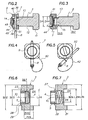
- la
figure 1 est une vue axialement éclatée d'un mode de réalisation pour un dispositif selon l'invention ; - les
figures 2 et 3 sont des coupes longitudinales du dispositif de lafigure 1 , illustrant de quelle façon un écrou et un piton coopèrent en vue du fonctionnement du dispositif ; - les
figures 4 et 5 sont des vues axiale de l'écrou respectivement en position verrouillée et déverrouillée ; - les
figures 6 et 7 sont des coupes longitudinales illustrant deux positions de moyens de rappel et de butée du dispositif de lafigure 1 ; et, - les
figures 8 à 11 illustrent différentes étapes de la mise en oeuvre du dispositif de lafigure 1 . - La
figure 1 illustre un dispositif de manutention 1 selon l'invention. Le dispositif 1 est organisé autour d'un axe longitudinal X1, représenté horizontalement. Ce dispositif de manutention est prévu pour venir se monter sur les trous oblongs d'un conteneur du type défini par les normes IS0668 et ISO1161. - A la
figure 1 , les principaux composants du dispositif 1 sont éclatés selon l'axe X1. On distingue d'avant en arrière, l'avant et l'arrière étant arbitrairement choisis ainsi, un piton 2, une butée 3, un ressort hélicoïdal 4, une entretoise 5, un anneau 6, un écrou 7 associé à une broche 8 et un pion 9. - Le piton 2 comprend, d'avant en arrière, un lardon 11, un arbre 12, une zone intermédiaire filetée 13 et un embout cylindrique 14. Il comprend en outre un passage 15, prévu pour recevoir la broche 8. La butée 3, le ressort 4, l'entretoise 5 et l'anneau 5 sont prévus pour se monter sur l'arbre 12. L'écrou 7 est prévu pour être vissé sur la zone filetée 13.
- Le lardon 11 a une forme transversale oblongue, complémentaire de celle d'un orifice 20 de manutention (voir
figures 8-11 ) d'un coin d'un conteneur tel que prévu par la norme ISO1161. Le lardon 11 est dimensionné de sorte que son passage dans l'orifice 20 se fait sans effort. Le lardon est symétrique relativement à l'axe X1. L'arbre 12, la zone 13 et l'embout 14 sont coaxiaux avec l'axe principal X1. L'arbre 12 s'étend vers l'arrière depuis le lardon 11. Le diamètre D12 de l'arbre 12 est inférieur à une largeur L11 du lardon 11. Le diamètre D13 de la zone filetée 13 est inférieur au diamètre D12 de l'arbre 12, et le diamètre D 14 de l'embout est inférieur au diamètre intérieur de du filetage de la zone filetée 13. - La butée 3 comprend un corps 21 de forme transversale oblongue, sensiblement identique à celle du lardon 11 et adaptée à pénétrer sans effort dans l'orifice 20. La profondeur P21, mesurée axialement, est supérieure à l'épaisseur P20 de la paroi 19 du coin ISO1161, au voisinage de l'orifice de manutention 20. La butée 3 comprend en outre un disque 22, à l'avant duquel s'étend le corps 21. Le disque est d'axe X1, et le diamètre D22 du disque 22 est sensiblement égal à la longueur L21 de la forme oblongue du corps 21, de sorte que, vu selon l'axe X1, le corps 21 est inscrit dans le disque 22. Comme particulièrement illustré aux
figures 6 et 7 , le disque 22 est prolongé vers l'arrière par une zone annulaire 23 de diamètre D23 inférieur au diamètre D22 du disque 22. Une empreinte ayant la forme d'gorge 24 est formée dans le corps 21, sensiblement transversalement à la dimension L21 la plus grande du corps 21. La largeur L24 de la gorge 24 est sensiblement identique à la largeur L11 du lardon 11, de sorte que le lardon puisse coulisser sans effort dans la gorge 24. La distance P24 entre le fond de la gorge 24 et la face avant du disque 22 est inférieure ou égale à l'épaisseur P20 de la paroi du coin ISO1161. - La butée comprend en outre un passage 26 pour l'arbre 12. Le diamètre D26 du passage 26 est sensiblement identique au diamètre D12 de l'arbre 12, de sorte que l'arbre 12 puisse s'y déplacer sans effort en translation et en rotation. Le passage 12 s'ouvre vers l'arrière sur un logement cylindrique 27 de diamètre D27 supérieur au diamètre D26. Le logement 27 est prévu pour y loger le ressort 4, comme particulièrement illustré aux
figures 6 et 7 . - L'entretoise est de forme cylindrique et elle est prévue pour coulisser à l'intérieur du logement 27 de la butée 3 en même temps qu'autour de l'arbre 12. Le ressort 4 est prévu pour être comprimé entre la butée 3 et l'entretoise 5. Les dimensions de l'entretoise 5, du ressort 4 et du logement 27, mesurées selon l'axe X, sont telles que dans la position de la
figure 6 , le ressort étant comprimé, l'entretoise est entièrement à l'intérieur du logement 27, sa face arrière étant affleurante 28 avec la face arrière 29 de la zone annulaire 23. - L'anneau comprend un corps 31et une anse 32. L'anse est articulée sur le corps autour d'un axe X6, transversal et non sécant avec l'axe principal X1. L'anse 32 s'étend sensiblement dans un plan incluant l'axe transversal X6. Le corps 31 est prévu pour être monté sur l'arbre 12. L'anse est prévue pour recevoir un crochet de levage ou un agrès d'arrimage pour le conteneur. Le corps 31 de l'anneau 6 est de forme symétrique relativement à un plan transversal à l'axe principal X1. Il est percé d'un orifice 33 pour le passage sans effort de l'arbre 12. Le corps 31 comprend à l'avant et à l'arrière de l'orifice 33, un renfoncement cylindrique 34 dont le diamètre D34 est supérieur au diamètre D33 de l'orifice 33. Celui des renfoncements 34 qui est à l'avant du corps est prévu pour recevoir et servir d'appui à la zone annulaire 23 de la butée 3.
- L'écrou 7 a une forme transversale sensiblement carrée, aux angles biseautés. La forme carrée permet une bonne prise en main, de sorte que l'écrou peut être manipulé sans utilisation d'un outil. L'écrou comprend un prolongement cylindrique 36 dont le diamètre s'inscrit dans le carré de l'écrou. Le prolongement cylindrique est prévu pour se loger et venir en appui dans celui des renfoncements 34, non visible aux figures, qui est à l'arrière du corps 31 de l'anneau 6. L'écrou comprend en outre un trou taraudé 38 le traversant axialement et prévu pour venir en prise sur la zone filetée 13 du piton 2. L'écrou comprend en outre, dans sa partie arrière 37 de forme carrée, de part et d'autre du trou taraudé 38, un passage transversal 39. Le passage 39 est prévu pour venir dans le prolongement du passage 15 du piton 2 et pour y introduire la broche 8. Comme particulièrement illustré aux
figures 2 et 3 , l'écrou 7 comprend aussi un logement cylindrique 41, ouvert vers l'arrière, et à l'avant duquel débouche le trou taraudé 38. Le diamètre intérieur D41 du logement 41 est supérieur au diamètre extérieur du taraudage du trou taraudé 38. - La broche 8 est une broche à bille, elle est maintenue reliée à l'écrou 7 par une chaînette 42.
- Le pion 9 comprend une tête plate 44, prolongée axialement vers l'avant par une tige 45. Comme particulièrement illustré aux
figures 2 et 3 , la tige 45 est prévue pour être introduite dans un logement cylindrique 46 correspondant, axialement percé dans l'embout 14 du piton 2. En outre, la tige 45 comprend un passage transversal 48 prévu pour venir en coïncidence avec un passage 49 correspondant de l'embout 14 afin d'y introduire une goupille élastique 51. - Le diamètre D44 de la tête 44 du pion 9 est inférieur au diamètre D41 du logement 41 de l'écrou 7. Ainsi, lorsque l'écrou 7 est dévissé, la tête 44 peut venir s'escamoter dans le logement 41. Le diamètre D44 est supérieur au diamètre extérieur du taraudage de l'écrou 7. Ainsi, lorsque l'écrou 7 est dévissé, la tête 44 peut venir en butée contre un épaulement formé entre le trou taraudé 38 et le logement 41. Lorsque l'écrou 7 est complètement vissé sur la zone filetée 13, sa face avant vient en butée contre un épaulement formé entre la zone filetée 13 et l'arbre 12.
- La goupille élastique 51 permet de fixer le pion 9 sur le piton 2, de façon indémontable par un utilisateur du dispositif de manutention 1. Ainsi, l'écrou est monté de façon imperdable sur le piton 2, entre deux positions, l'une dans laquelle l'écrou est totalement dévissé, en butée du la tête 44, l'autre totalement vissé, dans laquelle l'écrou est en butée sur l'arbre 12. La tête 44 pouvant pénétrer dans le logement 41 de l'écrou, cela évite qu'elle soit positionnée au-delà de l'écrou dans sa position dévissée, pour y former butée. La compacité du dispositif en bénéficie particulièrement. Un tel dispositif s'étend donc moins à l'extérieur du coin du conteneur.
- Le pion 9, l'écrou 7 et le piton 2 forment ensemble un boulon indémontable sur lequel l'ensemble des autres pièces 3-7 du dispositif 1 sont maintenues entre le lardon 11 et la tête 44, de façon imperdable et indémontable, la broche 8 étant elle-même reliée à cet ensemble par la chaînette 42. Le dispositif de manutention 1 selon l'invention constitue une pièce unique qui peut être utilisée sans autre accessoire et sans outil.
- La butée 3, le ressort 4 et l'entretoise 5 forment ensemble des moyens de rappel 3-5 qui tendent à ramener le piton vers l'arrière du dispositif.
- Comme particulièrement illustré à la
figure 5 , l'écrou comprend sans un de ses angles un passage 52 pour y disposer la broche 8, lorsqu'elle ne sert pas au blocage de l'écrou 7 sur l'arbre 12. - On va maintenant décrire le fonctionnement du dispositif 1, notamment en référence aux
figures 8 à 11 . Ces figures représentent partiellement un coin ISO1161 d'un conteneur 60. L'orifice de manutention 20 du conteneur, de forme oblongue, est disposé verticalement, c'est-à-dire que sa plus grande dimension est verticale. - A la
figure 8 , le dispositif de manutention 1 est représenté en vis-à-vis de l'orifice 20, prêt à y être introduit. Dans cette configuration, l'écrou est dévissé, dans sa position de lafigure 3 . Le lardon 11 est vertical, aligné avec le corps 11 de la butée, c'est-à-dire dans la position représentée en pointillée à lafigure 1 . Le lardon repose avant du corps 21 de la butée. Les moyens de rappel 3-5 sont dans leur position illustrée à lafigure 6 , le ressort 4 étant comprimé. - Dans cette configuration, le dispositif peut aisément être introduit dans l'orifice 20, comme cela est représenté à la
figure 9 . Pour verrouiller le dispositif 1 sur le conteneur 60, on tourne l'écrou 7 à la main, dans le sens de son dévissage. L'écrou étant déjà dans sa position dévissée, en butée sur la tête 44 du pion 9, cela a pour conséquence de faire pivoter le lardon 11. Lorsque le lardon est horizontal, c'est-à-dire qu'il arrive dans sa position illustrée en trait plein à lafigure 1 , il est en vis-à-vis de la gorge 24, au fond de laquelle il est immédiatement introduit par les moyens de rappel 3-5, tel que cela est illustré à lafigure 10 . - Dans la configuration de la
figure 10 , la paroi 19 du coin ISO1161 est alors pincée entre le lardon 11 et le disque 22. Les moyens de rappel sont dans leur position illustrée à lafigure 7 , le ressort étant décomprimé, de sort qu'un jeu J1 est apparu entre le disque 22, correspondant à l'enfoncement du lardon 11 dans la gorge 24. - Pour assurer le maintien du lardon 11 dans la gorge 24, on visse l'écrou 7, jusqu'à ce qu'il soit dans la position illustrée à la
figure 2 . Le dispositif est alors dans la configuration de lafigure 11 . Le jeu entre le corps 31 de l'anneau 6 a été réduit, de sorte qu'il ne subsiste qu'un jeu J2, insuffisant pour que le lardon 11 puisse échapper de la gorge 24 et suffisant pour permettre une rotation de l'anneau autour de l'axe principal X1. Ainsi, l'anneau peut librement tourner autour de l'arbre 12, de sorte qu'il peut s'aligner naturellement avec des élingues prévues pour lever le conteneur 60 ou bien être orienté l'anse vers le bas pour être utiliser à l'arrimage du conteneur sur le pont d'un navire, sur le plateau d'un camion ou dans la soute d'un aéronef. - Notamment lorsque le dispositif 1 est utilisé pour l'arrimage du conteneur, afin de garantir que l'écrou 7 ne se dévissera pas au cours du transport, on introduit la broche 8 dans les passages 15,39 prévus à cet effet dans l'écrou 7 et le piton 2, empêchant ainsi la rotation de l'écrou relativement au piton.
- Pour retirer le dispositif, il convient de faire les mêmes opérations dans un ordre et un sens inverses.
- Un tel dispositif est particulièrement compact, de sorte qu'il peut être laissé en place sur un conteneur, sans qu'il excède le gabarit routier. Il peut ainsi, être utilisé à la fois pour le chargement et le déchargement du conteneur sur le plateau d'un camion, et, pendant le transport, servir à l'arrimage du conteneur sur ce plateau. Ainsi, les risques d'accidents liés à la mise en place d'un tel dispositif en sont diminués, en même temps que le temps perdu à une telle opération.
- Bien sûr, l'invention n'est pas limitée aux exemples qui viennent d'être décrits.
- En particulier, si la description précédente a été faite en référence à la norme ISO1161, il est évident qu'un dispositif selon l'invention peut être adapté à un autre type de conteneur présentant notamment un orifice de manutention qui n'est pas circulaire, de sorte qu'une rotation d'un lardon de forme adaptée en empêche le retrait; quelle que soit la forme de l'orifice.
Claims (9)
- Dispositif (1) de manutention pour un conteneur (60) muni d'un orifice (20) de manutention, comprenant un anneau de manutention (6), un corps (21) et un lardon (11), le corps (21) et le lardon (11) étant mobiles l'un par rapport à l'autre en rotation autour d'un axe principal (X1) entre une première position dans laquelle ledit corps (21) et ledit lardon (11) présentent ensemble un profil transversal apte à traverser l'orifice de manutention (20), et une deuxième position, dans laquelle ledit corps (21) et ledit lardon (11) présentent, ensemble, un profil transversal inapte à traverser l'orifice de manutention (20), le corps comprenant en outre une empreinte (24) dans laquelle le lardon peut se loger lorsqu'il est dans la deuxième position, ledit dispositif comprenant aussi un arbre (12) s'étendant selon l'axe principal (X1), le lardon (11) étant disposé à une première extrémité dudit arbre (12), ledit arbre étant de préférence formé d'une seule pièce avec ledit lardon (11), l'arbre étant axialement prolongé à une deuxième extrémité opposée à la première par une zone filetée (13),
caractérisé en ce que
il comprend en outre un écrou (7) mobile, entre une position visée et une position dévissée, sur la zone filetée (13), la deuxième extrémité de l'arbre (12) portant une pièce de butée (44), la zone filetée (13) formant avec l'arbre (12) un épaulement, de sorte que le déplacement axial de l'écrou (7) est limité entre la pièce de butée (44), dans sa position dévissée, et ledit épaulement, dans sa position vissée. - Dispositif selon la revendication 1, caractérisé en ce qu'il comprend des moyens de rappel (3-5) disposés de sorte qu'ils tendent à faire pénétrer le lardon dans l'empreinte (24) lorsque ledit lardon est dans la deuxième position.
- Dispositif selon la revendication 1 ou 2, caractérisé en ce que dans la position dévissée la pièce de butée (44) est escamotée à l'intérieur d'un logement (41) de l'écrou (7).
- Dispositif selon la revendication 3, caractérisé en ce que les moyens de rappel (3-5) sont montés autour de l'arbre (12), entre le corps (11) et l'écrou (7).
- Dispositif selon l'une des revendications 1 à 4, caractérisé en ce qu'il comprend une butée (22), formant de préférence une seule pièce avec le corps (21), et disposée de sorte que dans la deuxième position, ladite butée et le lardon (11) puissent être disposés chacun d'un côté de l'orifice de manutention (20).
- Dispositif selon la revendication 5, caractérisé en ce qu'il comprend des moyens (8, 15, 39) pour bloquer l'écrou (7) dans sa position vissée.
- Dispositif selon l'une des revendications 1 à 6, caractérisé en ce que l'anneau (6) comprend un corps (31) monté mobile en rotation autour de l'arbre (12), l'anneau (6) comprenant en outre une anse (32), de préférence articulée sur le corps (31) autour d'un axe (X6) transversal à l'axe principal (X1).
- Dispositif selon l'une des revendications 1 à 6 et 7, caractérisé en ce que le corps (31) de l'anneau (6) est monté sur l'arbre (12) entre l'écrou (7) et les moyens de rappel (3-5).
- Dispositif selon l'une des revendications précédentes, caractérisé en ce qu'il est adapté à la manutention de conteneurs définis par les normes ISO668 et ISO1161.
Applications Claiming Priority (2)
| Application Number | Priority Date | Filing Date | Title |
|---|---|---|---|
| FR0956805A FR2950617B1 (fr) | 2009-09-30 | 2009-09-30 | Dispositif de manutention et d'arrimage, notamment pour conteneur iso. |
| PCT/FR2010/052018 WO2011039456A1 (fr) | 2009-09-30 | 2010-09-27 | Dispositif de manutention et d'arrimage, notamment pour conteneur iso |
Publications (2)
| Publication Number | Publication Date |
|---|---|
| EP2483193A1 EP2483193A1 (fr) | 2012-08-08 |
| EP2483193B1 true EP2483193B1 (fr) | 2014-01-15 |
Family
ID=42173408
Family Applications (1)
| Application Number | Title | Priority Date | Filing Date |
|---|---|---|---|
| EP10769031.5A Active EP2483193B1 (fr) | 2009-09-30 | 2010-09-27 | Dispositif de manutention et d'arrimage, notamment pour conteneur iso |
Country Status (4)
| Country | Link |
|---|---|
| EP (1) | EP2483193B1 (fr) |
| ES (1) | ES2456497T3 (fr) |
| FR (1) | FR2950617B1 (fr) |
| WO (1) | WO2011039456A1 (fr) |
Families Citing this family (2)
| Publication number | Priority date | Publication date | Assignee | Title |
|---|---|---|---|---|
| WO2017045037A1 (fr) * | 2015-09-16 | 2017-03-23 | C & J Rigging Pty Ltd | Connecteur de pièce de coin de conteneur intermodal |
| US12214714B2 (en) | 2020-04-29 | 2025-02-04 | Sean Phoenix Jones | Shipping container fastener and method |
Family Cites Families (5)
| Publication number | Priority date | Publication date | Assignee | Title |
|---|---|---|---|---|
| FR2102616A6 (fr) * | 1970-08-06 | 1972-04-07 | Stas | |
| US4068878A (en) * | 1976-09-28 | 1978-01-17 | The United States Of America As Represented By The Secretary Of The Navy | Container lift coupling |
| US4139228A (en) * | 1977-06-13 | 1979-02-13 | Israel Aircraft Industries Ltd. | Quarter-turn locking device |
| JPH07172758A (ja) * | 1993-12-21 | 1995-07-11 | Sekisui Chem Co Ltd | 吊り具とその取り付け方法 |
| NL1023202C2 (nl) * | 2003-04-16 | 2004-10-19 | Faget B V | Samenstel van te hijsen voorwerp en hijsmiddel daarvoor. |
-
2009
- 2009-09-30 FR FR0956805A patent/FR2950617B1/fr not_active Expired - Fee Related
-
2010
- 2010-09-27 ES ES10769031.5T patent/ES2456497T3/es active Active
- 2010-09-27 WO PCT/FR2010/052018 patent/WO2011039456A1/fr not_active Ceased
- 2010-09-27 EP EP10769031.5A patent/EP2483193B1/fr active Active
Also Published As
| Publication number | Publication date |
|---|---|
| WO2011039456A1 (fr) | 2011-04-07 |
| FR2950617B1 (fr) | 2012-08-24 |
| ES2456497T3 (es) | 2014-04-22 |
| EP2483193A1 (fr) | 2012-08-08 |
| FR2950617A1 (fr) | 2011-04-01 |
Similar Documents
| Publication | Publication Date | Title |
|---|---|---|
| EP1961531B1 (fr) | Dispositif de serrage à bras de manoeuvre escamotable et appareil comportant un tel dispositif | |
| EP2082403B1 (fr) | Conteneur pour le stockage de dechets radioactifs | |
| EP2243972A1 (fr) | Maillon d'attache à bague rotative verrouillable | |
| CA2199495A1 (fr) | Remote manoeuvrable snap-hook to make a rope fast | |
| EP2431555B1 (fr) | Verrou de trappe extérieur | |
| EP3838666B1 (fr) | Support de levage de conteneur par des orifices supérieurs du conteneur | |
| FR2987856A1 (fr) | Attache en deux parties pour le support et la fixation d'une structure de travail en encorbellement a un mur | |
| WO2011039456A1 (fr) | Dispositif de manutention et d'arrimage, notamment pour conteneur iso | |
| EP1978838B1 (fr) | Bagage a main du type remorquable equipe d ' une poignee telescopique amortie | |
| EP2632842B1 (fr) | Dispositif de manutention, notamment pour conteneur normalisé | |
| WO2012143474A1 (fr) | Système de connexion pour la fixation d'un dispositif de portage | |
| FR3075847A1 (fr) | Verrou et trappe comprenant un tel verrou | |
| FR3020827A1 (fr) | Dispositif antivol pour benne amovible | |
| FR2585787A1 (fr) | Dispositif autobloquant destine a remplacer l'ecrou visse sur l'axe des apparaux et, notamment, des grosses manilles | |
| EP4219077A1 (fr) | Outil de vissage/dévissage adapté pour une vis ou un boulon difficile d accès | |
| FR2897027A1 (fr) | Dispositif d'arrimage d'un transpalette sur le plateau d'un camion | |
| FR3058993A1 (fr) | Outil de manutention et de deversement d'un fut pour un chariot telescopique | |
| WO2025257282A1 (fr) | Dispositif pour amarrer un conteneur de type maritime | |
| EP3181506A1 (fr) | Anneau de levage a verrouillage tangentiel | |
| FR3020351A1 (fr) | Dispositif de chargement en dechets d'une benne de dechetterie depuis une plateforme | |
| FR3158331A1 (fr) | Dispositif de verrouillage/deverrouillage et élément pivotant muni d’un tel dispositif de verrouillage/ deverrouillage | |
| FR2643352A1 (fr) | Crochet de prehension en deux parties pour appareil de halage a bras, notamment pour potence de chargement/dechargement | |
| FR2987353A1 (fr) | Outillage de levage | |
| EP3165807B1 (fr) | Chapeau de protection d'une bouteille de gaz | |
| FR3005645A1 (fr) | Dispositif d'ancrage d'une charge, en vue du levage de cette charge |
Legal Events
| Date | Code | Title | Description |
|---|---|---|---|
| PUAI | Public reference made under article 153(3) epc to a published international application that has entered the european phase |
Free format text: ORIGINAL CODE: 0009012 |
|
| 17P | Request for examination filed |
Effective date: 20120312 |
|
| AK | Designated contracting states |
Kind code of ref document: A1 Designated state(s): AL AT BE BG CH CY CZ DE DK EE ES FI FR GB GR HR HU IE IS IT LI LT LU LV MC MK MT NL NO PL PT RO SE SI SK SM TR |
|
| DAX | Request for extension of the european patent (deleted) | ||
| GRAP | Despatch of communication of intention to grant a patent |
Free format text: ORIGINAL CODE: EPIDOSNIGR1 |
|
| INTG | Intention to grant announced |
Effective date: 20130808 |
|
| GRAS | Grant fee paid |
Free format text: ORIGINAL CODE: EPIDOSNIGR3 |
|
| GRAA | (expected) grant |
Free format text: ORIGINAL CODE: 0009210 |
|
| AK | Designated contracting states |
Kind code of ref document: B1 Designated state(s): AL AT BE BG CH CY CZ DE DK EE ES FI FR GB GR HR HU IE IS IT LI LT LU LV MC MK MT NL NO PL PT RO SE SI SK SM TR |
|
| REG | Reference to a national code |
Ref country code: GB Ref legal event code: FG4D Free format text: NOT ENGLISH Ref country code: CH Ref legal event code: EP |
|
| REG | Reference to a national code |
Ref country code: AT Ref legal event code: REF Ref document number: 649742 Country of ref document: AT Kind code of ref document: T Effective date: 20140215 |
|
| REG | Reference to a national code |
Ref country code: IE Ref legal event code: FG4D Free format text: LANGUAGE OF EP DOCUMENT: FRENCH |
|
| REG | Reference to a national code |
Ref country code: DE Ref legal event code: R096 Ref document number: 602010013168 Country of ref document: DE Effective date: 20140227 |
|
| REG | Reference to a national code |
Ref country code: ES Ref legal event code: FG2A Ref document number: 2456497 Country of ref document: ES Kind code of ref document: T3 Effective date: 20140422 |
|
| REG | Reference to a national code |
Ref country code: NL Ref legal event code: VDEP Effective date: 20140115 |
|
| REG | Reference to a national code |
Ref country code: AT Ref legal event code: MK05 Ref document number: 649742 Country of ref document: AT Kind code of ref document: T Effective date: 20140115 |
|
| REG | Reference to a national code |
Ref country code: LT Ref legal event code: MG4D |
|
| PG25 | Lapsed in a contracting state [announced via postgrant information from national office to epo] |
Ref country code: NO Free format text: LAPSE BECAUSE OF FAILURE TO SUBMIT A TRANSLATION OF THE DESCRIPTION OR TO PAY THE FEE WITHIN THE PRESCRIBED TIME-LIMIT Effective date: 20140415 Ref country code: IS Free format text: LAPSE BECAUSE OF FAILURE TO SUBMIT A TRANSLATION OF THE DESCRIPTION OR TO PAY THE FEE WITHIN THE PRESCRIBED TIME-LIMIT Effective date: 20140515 Ref country code: LT Free format text: LAPSE BECAUSE OF FAILURE TO SUBMIT A TRANSLATION OF THE DESCRIPTION OR TO PAY THE FEE WITHIN THE PRESCRIBED TIME-LIMIT Effective date: 20140115 |
|
| PG25 | Lapsed in a contracting state [announced via postgrant information from national office to epo] |
Ref country code: CY Free format text: LAPSE BECAUSE OF FAILURE TO SUBMIT A TRANSLATION OF THE DESCRIPTION OR TO PAY THE FEE WITHIN THE PRESCRIBED TIME-LIMIT Effective date: 20140115 Ref country code: NL Free format text: LAPSE BECAUSE OF FAILURE TO SUBMIT A TRANSLATION OF THE DESCRIPTION OR TO PAY THE FEE WITHIN THE PRESCRIBED TIME-LIMIT Effective date: 20140115 Ref country code: AT Free format text: LAPSE BECAUSE OF FAILURE TO SUBMIT A TRANSLATION OF THE DESCRIPTION OR TO PAY THE FEE WITHIN THE PRESCRIBED TIME-LIMIT Effective date: 20140115 Ref country code: FI Free format text: LAPSE BECAUSE OF FAILURE TO SUBMIT A TRANSLATION OF THE DESCRIPTION OR TO PAY THE FEE WITHIN THE PRESCRIBED TIME-LIMIT Effective date: 20140115 Ref country code: SE Free format text: LAPSE BECAUSE OF FAILURE TO SUBMIT A TRANSLATION OF THE DESCRIPTION OR TO PAY THE FEE WITHIN THE PRESCRIBED TIME-LIMIT Effective date: 20140115 Ref country code: PT Free format text: LAPSE BECAUSE OF FAILURE TO SUBMIT A TRANSLATION OF THE DESCRIPTION OR TO PAY THE FEE WITHIN THE PRESCRIBED TIME-LIMIT Effective date: 20140515 |
|
| PG25 | Lapsed in a contracting state [announced via postgrant information from national office to epo] |
Ref country code: LV Free format text: LAPSE BECAUSE OF FAILURE TO SUBMIT A TRANSLATION OF THE DESCRIPTION OR TO PAY THE FEE WITHIN THE PRESCRIBED TIME-LIMIT Effective date: 20140115 Ref country code: HR Free format text: LAPSE BECAUSE OF FAILURE TO SUBMIT A TRANSLATION OF THE DESCRIPTION OR TO PAY THE FEE WITHIN THE PRESCRIBED TIME-LIMIT Effective date: 20140115 |
|
| REG | Reference to a national code |
Ref country code: DE Ref legal event code: R097 Ref document number: 602010013168 Country of ref document: DE |
|
| PG25 | Lapsed in a contracting state [announced via postgrant information from national office to epo] |
Ref country code: RO Free format text: LAPSE BECAUSE OF FAILURE TO SUBMIT A TRANSLATION OF THE DESCRIPTION OR TO PAY THE FEE WITHIN THE PRESCRIBED TIME-LIMIT Effective date: 20140115 Ref country code: EE Free format text: LAPSE BECAUSE OF FAILURE TO SUBMIT A TRANSLATION OF THE DESCRIPTION OR TO PAY THE FEE WITHIN THE PRESCRIBED TIME-LIMIT Effective date: 20140115 Ref country code: CZ Free format text: LAPSE BECAUSE OF FAILURE TO SUBMIT A TRANSLATION OF THE DESCRIPTION OR TO PAY THE FEE WITHIN THE PRESCRIBED TIME-LIMIT Effective date: 20140115 Ref country code: DK Free format text: LAPSE BECAUSE OF FAILURE TO SUBMIT A TRANSLATION OF THE DESCRIPTION OR TO PAY THE FEE WITHIN THE PRESCRIBED TIME-LIMIT Effective date: 20140115 |
|
| PLBE | No opposition filed within time limit |
Free format text: ORIGINAL CODE: 0009261 |
|
| STAA | Information on the status of an ep patent application or granted ep patent |
Free format text: STATUS: NO OPPOSITION FILED WITHIN TIME LIMIT |
|
| PG25 | Lapsed in a contracting state [announced via postgrant information from national office to epo] |
Ref country code: SK Free format text: LAPSE BECAUSE OF FAILURE TO SUBMIT A TRANSLATION OF THE DESCRIPTION OR TO PAY THE FEE WITHIN THE PRESCRIBED TIME-LIMIT Effective date: 20140115 Ref country code: PL Free format text: LAPSE BECAUSE OF FAILURE TO SUBMIT A TRANSLATION OF THE DESCRIPTION OR TO PAY THE FEE WITHIN THE PRESCRIBED TIME-LIMIT Effective date: 20140115 |
|
| 26N | No opposition filed |
Effective date: 20141016 |
|
| REG | Reference to a national code |
Ref country code: DE Ref legal event code: R097 Ref document number: 602010013168 Country of ref document: DE Effective date: 20141016 |
|
| PG25 | Lapsed in a contracting state [announced via postgrant information from national office to epo] |
Ref country code: MC Free format text: LAPSE BECAUSE OF FAILURE TO SUBMIT A TRANSLATION OF THE DESCRIPTION OR TO PAY THE FEE WITHIN THE PRESCRIBED TIME-LIMIT Effective date: 20140115 |
|
| REG | Reference to a national code |
Ref country code: CH Ref legal event code: PL |
|
| PG25 | Lapsed in a contracting state [announced via postgrant information from national office to epo] |
Ref country code: SI Free format text: LAPSE BECAUSE OF FAILURE TO SUBMIT A TRANSLATION OF THE DESCRIPTION OR TO PAY THE FEE WITHIN THE PRESCRIBED TIME-LIMIT Effective date: 20140115 |
|
| REG | Reference to a national code |
Ref country code: IE Ref legal event code: MM4A |
|
| PG25 | Lapsed in a contracting state [announced via postgrant information from national office to epo] |
Ref country code: BE Free format text: LAPSE BECAUSE OF NON-PAYMENT OF DUE FEES Effective date: 20140930 |
|
| PG25 | Lapsed in a contracting state [announced via postgrant information from national office to epo] |
Ref country code: CH Free format text: LAPSE BECAUSE OF NON-PAYMENT OF DUE FEES Effective date: 20140930 Ref country code: LI Free format text: LAPSE BECAUSE OF NON-PAYMENT OF DUE FEES Effective date: 20140930 |
|
| PG25 | Lapsed in a contracting state [announced via postgrant information from national office to epo] |
Ref country code: IE Free format text: LAPSE BECAUSE OF NON-PAYMENT OF DUE FEES Effective date: 20140927 |
|
| PG25 | Lapsed in a contracting state [announced via postgrant information from national office to epo] |
Ref country code: SM Free format text: LAPSE BECAUSE OF FAILURE TO SUBMIT A TRANSLATION OF THE DESCRIPTION OR TO PAY THE FEE WITHIN THE PRESCRIBED TIME-LIMIT Effective date: 20140115 |
|
| PG25 | Lapsed in a contracting state [announced via postgrant information from national office to epo] |
Ref country code: BG Free format text: LAPSE BECAUSE OF FAILURE TO SUBMIT A TRANSLATION OF THE DESCRIPTION OR TO PAY THE FEE WITHIN THE PRESCRIBED TIME-LIMIT Effective date: 20140115 Ref country code: MT Free format text: LAPSE BECAUSE OF FAILURE TO SUBMIT A TRANSLATION OF THE DESCRIPTION OR TO PAY THE FEE WITHIN THE PRESCRIBED TIME-LIMIT Effective date: 20140115 Ref country code: GR Free format text: LAPSE BECAUSE OF FAILURE TO SUBMIT A TRANSLATION OF THE DESCRIPTION OR TO PAY THE FEE WITHIN THE PRESCRIBED TIME-LIMIT Effective date: 20140416 Ref country code: IT Free format text: LAPSE BECAUSE OF FAILURE TO SUBMIT A TRANSLATION OF THE DESCRIPTION OR TO PAY THE FEE WITHIN THE PRESCRIBED TIME-LIMIT Effective date: 20140115 |
|
| REG | Reference to a national code |
Ref country code: FR Ref legal event code: PLFP Year of fee payment: 7 |
|
| PG25 | Lapsed in a contracting state [announced via postgrant information from national office to epo] |
Ref country code: HU Free format text: LAPSE BECAUSE OF FAILURE TO SUBMIT A TRANSLATION OF THE DESCRIPTION OR TO PAY THE FEE WITHIN THE PRESCRIBED TIME-LIMIT; INVALID AB INITIO Effective date: 20100927 Ref country code: TR Free format text: LAPSE BECAUSE OF FAILURE TO SUBMIT A TRANSLATION OF THE DESCRIPTION OR TO PAY THE FEE WITHIN THE PRESCRIBED TIME-LIMIT Effective date: 20140115 |
|
| REG | Reference to a national code |
Ref country code: FR Ref legal event code: PLFP Year of fee payment: 8 |
|
| PG25 | Lapsed in a contracting state [announced via postgrant information from national office to epo] |
Ref country code: MK Free format text: LAPSE BECAUSE OF FAILURE TO SUBMIT A TRANSLATION OF THE DESCRIPTION OR TO PAY THE FEE WITHIN THE PRESCRIBED TIME-LIMIT Effective date: 20140115 |
|
| REG | Reference to a national code |
Ref country code: FR Ref legal event code: PLFP Year of fee payment: 9 |
|
| PG25 | Lapsed in a contracting state [announced via postgrant information from national office to epo] |
Ref country code: AL Free format text: LAPSE BECAUSE OF FAILURE TO SUBMIT A TRANSLATION OF THE DESCRIPTION OR TO PAY THE FEE WITHIN THE PRESCRIBED TIME-LIMIT Effective date: 20140115 |
|
| PGFP | Annual fee paid to national office [announced via postgrant information from national office to epo] |
Ref country code: LU Payment date: 20250929 Year of fee payment: 16 |
|
| PGFP | Annual fee paid to national office [announced via postgrant information from national office to epo] |
Ref country code: GB Payment date: 20250929 Year of fee payment: 16 |
|
| PGFP | Annual fee paid to national office [announced via postgrant information from national office to epo] |
Ref country code: FR Payment date: 20250926 Year of fee payment: 16 |
|
| PGFP | Annual fee paid to national office [announced via postgrant information from national office to epo] |
Ref country code: DE Payment date: 20251029 Year of fee payment: 16 |
|
| PGFP | Annual fee paid to national office [announced via postgrant information from national office to epo] |
Ref country code: ES Payment date: 20251210 Year of fee payment: 16 |