EP2483482B1 - Dispositif de retenue de dent d'excavatrice - Google Patents
Dispositif de retenue de dent d'excavatrice Download PDFInfo
- Publication number
- EP2483482B1 EP2483482B1 EP10819761.7A EP10819761A EP2483482B1 EP 2483482 B1 EP2483482 B1 EP 2483482B1 EP 10819761 A EP10819761 A EP 10819761A EP 2483482 B1 EP2483482 B1 EP 2483482B1
- Authority
- EP
- European Patent Office
- Prior art keywords
- wedge
- clamp
- bucket
- retention device
- fork
- Prior art date
- Legal status (The legal status is an assumption and is not a legal conclusion. Google has not performed a legal analysis and makes no representation as to the accuracy of the status listed.)
- Active
Links
Images


Classifications
-
- E—FIXED CONSTRUCTIONS
- E02—HYDRAULIC ENGINEERING; FOUNDATIONS; SOIL SHIFTING
- E02F—DREDGING; SOIL-SHIFTING
- E02F9/00—Component parts of dredgers or soil-shifting machines, not restricted to one of the kinds covered by groups E02F3/00 - E02F7/00
- E02F9/28—Small metalwork for digging elements, e.g. teeth scraper bits
- E02F9/2808—Teeth
- E02F9/2816—Mountings therefor
- E02F9/2833—Retaining means, e.g. pins
-
- E—FIXED CONSTRUCTIONS
- E02—HYDRAULIC ENGINEERING; FOUNDATIONS; SOIL SHIFTING
- E02F—DREDGING; SOIL-SHIFTING
- E02F9/00—Component parts of dredgers or soil-shifting machines, not restricted to one of the kinds covered by groups E02F3/00 - E02F7/00
- E02F9/28—Small metalwork for digging elements, e.g. teeth scraper bits
- E02F9/2808—Teeth
- E02F9/2816—Mountings therefor
- E02F9/2825—Mountings therefor using adapters
Definitions
- the invention relates to excavator equipment with a bucket or shovel of the type having teeth, and in particular to a retaining device for retaining teeth on the shovel or bucket of such equipment, in which the retaining device can be fastened and released without the use of hammers.
- Excavators usually have a bucket or shovel, and teeth are attached to the leading edge of the bucket, to assist in penetrating the material.
- the teeth are subject to heavy wear. They are replaced at frequent service intervals.
- Tooth retention devices are provided which attach to the leading edge of the bucket. These devices have mechanisms which secure the individual teeth. They permit the release and replacement of the teeth as required.
- the tooth retention devices are also subject to heavy wear. They are releasably secured to the leading edge of the bucket. They must also be removed and replaced as required.
- the invention is directed to such tooth retention devices, and to a system for attaching and releasing them without the use of hammers.
- the '529 patent discloses a retaining device for retaining a digging component on a lip of a bucket.
- the retaining device of the '529 patent includes a keeper wedge with protrusions bearing against the digging component.
- the '529 patent also discloses a wedge member interposed between a forward surface of the lip and the digging component.
- the keeper wedge has at least one angled face and the wedge member has a pair of angled faces, at least one of which bears against the angled face of the keeper wedge.
- the wedge member is retained in position by a tension bolt.
- WO 00/20696 to Emrich et al. published on April 13, 2000 discloses a wedging device for insertion between components such as an adaptor and a dragline bucket.
- the wedging device of the '696 publication has a typically C-shaped insert cooperating with a wedge element.
- the insert and the wedge element are interconnected by a tensioning screw that engages with a lateral arm projecting from the insert.
- WO 2008/140878 to Ruvang published on November 20, 2008 discloses a C-clamp and wedge connector system extending through aligned openings in a ground-engaging wear member and a support structure that retains the wear member.
- the C-clamp of the '878 publication includes a wedge structure, spool structure, rotatable screw member and a tongue-and-groove interconnection.
- the invention seeks to provide a tooth retention device for attachment to an excavator bucket, as claimed in claim 1 below.
- the wedge is generally tapered from a narrow end to a wider end and the clamp has a wedge engaging surface angled to receive the tapered wedge.
- the lip of the bucket is formed with an opening through which the clamp can be passed, and the lip of the bucket has a wedge engaging surface for receiving the wedge.
- the lip of the bucket is also formed with diverging pressure surfaces and the clamp is formed with diverging clamping surfaces, the respective surfaces being inter engageable when the wedge is inserted.
- the clamp also has wedge receiving recesses, through which the wedge can be inserted between the clamp and the lip so that when the block on the wedge is tightened up, the lip and the clamp are forced apart, thereby forcing the clamp into engagement with the lip.
- a resilient cap which can be applied to the top of the rod, and the rod has a head, receiving the cap, so as to protect the head of the threaded rod from damage.
- the threaded rod has an annular collar
- the wedge has a semi annular recess, with the collar fitting within the recess, while permitting the threaded rod to be rotated.
- the wedge has a wedge block with a wedge rack portion.
- the clamp has a clamp rack portion, the two rack portions being inter engagable securely.
- the wedge block has a threaded bore, and through the threaded bore, the threaded rod is connected so that the block can be tightened up.
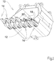
- FIG. 1 it will be seen that the invention is illustrated there in relation to an excavator bucket (10).
- the bucket is mounted on any of a variety of pieces of excavator equipment (not shown) which require no description.
- the bucket has a leading lower lip or edge (12) provided with a plurality of tooth members (14).
- Each tooth is retained on an individual tooth retention device (16).
- the tooth retention devices are secured to the lip (12) at spaced intervals.
- Each tooth can be attached to and removed from its tooth retention device by means known in the art and requiring no description.
- the tooth retention device (16) is also releasable and replaceable, as and when required.
- the attachment system used for this purpouse involved the use of simple metal wedge pieces, which were hammered into a space in the tooth retention device. Removal involved hammering the wedges pieces, in the opposite direction, to release them.
- the invention is directed to a tooth retention device having an improved attachment for securing the tooth retention devices to the bucket, and enabling its release for replacement in a quicker more efficient manner.
- a first embodiment of the tooth retention device is shown in more detail in Figs 2 and 3 ;
- the tooth retention device (16) of this embodiment comprises a main body (18) having a forwardly extending tooth mounting portion (20) formed integrally. This support fits into the tooth (T)in known manner, and the tooth is secured in known manner.
- the lip or edge (12) is formed with clamp openings (26) and angled diverging pressure surfaces (30).
- the arms (22) and (24) are formed with respective clamp receiving openings (28).
- C - shaped clamps (32) are shaped and adapted to fit through clamp openings (28), in arms (22), (24), and through clamp openings (26) in the edge (12).
- the upper and lower edges (34) of the C clamp are formed at angles as to make a tapered wedging fit against angled surfaces (30) of lip (12)
- the C clamp (32) is formed with a rectangular recess (36).
- Each retention device is provided with a releasable wedge member (38).
- Wedge member (38) consists of an integral wedge body (40) tapering from a wide upper end to a narrower lower end, and having a generally U-shaped channel (42), with a semi-annular ridge (44) at its upper end.
- a threaded rod (46) Within channel (42) there is a threaded rod (46), with an annular groove (48) for receiving the ridge (44).
- a C clamp (32) is then slid through the clamp slots (28) and clamp opening (26), with its upper and lower angled surfaces (34) fitting over the angled surfaces (30).
- a wedge member (38) is then slid down into the clamp slots (28) and clamp opening (26).
- the block (50) will then contact the C clamp (32) within rectangular space (36).
- Removal of the retention device (10) proceeds in the opposite manner by reversing rod (46) and thus releasing the block (50) from the C clamp (32).
- FIG. 4 A further embodiment of the invention is illustrated in Figures 4 , 5 & 6 .
- the wedge member is illustrated as (60).
- the wedge member (60) has a wedge body (62) tapering from a wide upper end to a narrower lower end.
- the wedge body (62) has a generally u-shaped channel (64).
- a semi-annular ridge (66) forming a collar.
- a threaded rod (68) has a head portion (30) with an annular groove (72) formed around it, to receive the ridge (66).
- a block nut (74) is threadedly received on the threaded rod (68).
- the block nut (74) has a ridged rack portion (76) extending therefrom normal to the axis of the nut (74)
- the C clamp (32) in this embodiment is somewhat modified. It has a clamp rack portion (78) formed thereon, located in a generally rectangular shaped block (80) extending upwardly and downwardly, and receiving rack (76) of the block nut (74).
- the threaded rod is first of all rotated so as to drive the block nut down to the lower most point on the rod.
- the wedge member is then inserted, in the same way as before in the previous embodiment, seating against the lip of the shovel.
- the threaded rack portion (76) on the block nut (74) will engage the lower most ridges of the clamp rack portion (78) on the C clamp (32).
- the rod (68) is then rotated, by a suitable tool such as an allen key (not shown). This will cause the block nut (74) to progress up the threaded rod (68).
- rack portion (76) is engaging the rack portion (78) of the C-clamp (32), the block nut (74) cannot move upwardly.
- a cap (80) typically formed of resilient synthetic plastic material or the like, will be press fitted onto the top of the nut (74), thereby preventing it from rotating. At the same time it will prevent the entry of foreign matter, which might damage the key surfaces on the nut head, and make it difficult to remove.
- a cap is also used in the embodiment of Figs 2 and 3 .
- the cap (80) has internal ridges formed to inter-engage with grooves on the head of the rod. This will resist any tendency for the thread not to be loosened during use.
Landscapes
- Engineering & Computer Science (AREA)
- Mining & Mineral Resources (AREA)
- Civil Engineering (AREA)
- General Engineering & Computer Science (AREA)
- Structural Engineering (AREA)
- Component Parts Of Construction Machinery (AREA)
- Earth Drilling (AREA)
- Clamps And Clips (AREA)
Claims (7)
- Dispositif de retenue de dent (16) destiné à être fixé au bord d'un godet d'excavatrice (10),
ledit godet (10) définissant une ouverture d'agrafe de godet (26), le dispositif de retenue de dent (16) comportant :une partie de montage de dent (20) ;un corps en forme de fourche (18, 22, 24) formant une partie de ladite partie de montage de dent (20) s'ajustant sur ledit bord (12) dudit godet (10), ledit corps en forme de fourche définissant une ouverture d'agrafe de fourche (28) calée avec l'ouverture d'agrafe de godet (26) ;un agrafe généralement en forme de C (32) passant par ladite ouverture d'agrafe de godet (26) et ladite ouverture d'agrafe de fourche (28) dans ledit corps en forme de fourche (22, 24) ;un coin (38) située le long de ladite agrafe (32) et s'étendant dans ladite ouverture d'agrafe de fourche (28) et ladite ouverture d'agrafe de godet (26) et maintenant l'agrafe (32) en position et ledit coin (38) comprenant un canal de coin (42) ;une tige filetée (46) reçue dans ledit canal de coin (42) dans ledit coin (38) ; le dispositif caractérisé en ce qu'il existe un bloc de coin fileté (50) reçu dans ledit canal de coin (42) entre ledit coin (38) et ladite agrafe (32) et la tige (46) pouvant être tournée pour déplacer le bloc de coin (50) le long de la tige (46) entre des positions verrouillée et dégagée ;le canal de coin (42) présentant un pli semi-annulaire (44) formé à l'intérieur de celui-ci et la tige (46) présentant une rainure annulaire (48) pour recevoir ce pli (44). - Dispositif de retenue de dent (16) tel que défini dans la revendication 1 et caractérisé en ce que ledit coin (38) présente une forme généralement effilée d'une extrémité plus étroite vers une extrémité plus large.
- Dispositif de retenue de dent (16) tel que défini dans la revendication 2 caractérisé en ce que ladite agrafe (32) comporte un bloc de coin (50) recevant un évidement (36), et dans lequel ledit bloc de coin (50) peut être déplacé le long dudit évidement (36) entre des positions verrouillée et dégagée.
- Dispositif de retenue de dent (16) tel que défini dans la revendication 3, caractérisé en ce que ladite tige filetée (68) est formée avec une tête (70) à une extrémité, et comprenant un capuchon élastique (80) conçu pour amener un frottement à s'ajuster sur ladite tête (70), permettant ainsi de retenir celle-ci contre une rotation éventuelle.
- Dispositif de retenue de dent (16) tel que défini dans la revendication 4 et comprenant un évidement de col généralement annulaire (66) formé dans ladite tige et une collerette semi-circulaire (72) formée sur ledit canal, et reçue dans ledit évidement annulaire.
- Dispositif de retenue de dent (16) tel que défini dans la revendication 1 et caractérisé en outre en ce que le corps en forme de fourche (22, 24) est formé avec des surfaces de serrage divergentes supérieure et inférieure (30), et dans lequel ladite agrafe (32) est formée avec des surfaces de serrage supérieure et inférieure (34), divergentes l'une de l'autre, et conçues pour s'intercaler entre lesdites surfaces de serrage (30) dudit corps en forme de fourche (22, 24).
- Dispositif de retenue de dent (16) tel que défini dans la revendication 6 et comprenant en outre un godet d'excavatrice (10), une partie de lèvre (12) sur ledit godet (10), s'insérant dans ledit corps en forme de fourche (22, 24), et ladite ouverture d'agrafe de godet (26) étant formée par le biais de ladite partie de lèvre (12), et une surface de calage définie par un bord latéral de ladite partie de lèvre, ledit coin (38) étant conçu pour mettre en prise ladite surface de calage (12), sur un côté dudit coin et ledit coin étant conçu pour mettre en prise ladite agrafe (32) sur la surface opposée dudit coin, permettant ainsi d'écarter ladite agrafe (32) de ladite surface de calage de ladite partie de lèvre (10).
Applications Claiming Priority (2)
| Application Number | Priority Date | Filing Date | Title |
|---|---|---|---|
| US27248709P | 2009-09-29 | 2009-09-29 | |
| PCT/CA2010/001470 WO2011038482A1 (fr) | 2009-09-29 | 2010-09-20 | Dispositif de retenue de dent d'excavatrice |
Publications (3)
| Publication Number | Publication Date |
|---|---|
| EP2483482A1 EP2483482A1 (fr) | 2012-08-08 |
| EP2483482A4 EP2483482A4 (fr) | 2017-01-18 |
| EP2483482B1 true EP2483482B1 (fr) | 2019-10-30 |
Family
ID=43778707
Family Applications (1)
| Application Number | Title | Priority Date | Filing Date |
|---|---|---|---|
| EP10819761.7A Active EP2483482B1 (fr) | 2009-09-29 | 2010-09-20 | Dispositif de retenue de dent d'excavatrice |
Country Status (14)
| Country | Link |
|---|---|
| US (2) | US8458931B2 (fr) |
| EP (1) | EP2483482B1 (fr) |
| JP (1) | JP2013506065A (fr) |
| KR (1) | KR101750123B1 (fr) |
| CN (1) | CN102575460B (fr) |
| AU (2) | AU2010302883B2 (fr) |
| BR (1) | BR112012006856A2 (fr) |
| CA (1) | CA2774602C (fr) |
| CL (1) | CL2012000672A1 (fr) |
| EA (1) | EA024047B1 (fr) |
| ES (1) | ES2767253T3 (fr) |
| MX (1) | MX2012003580A (fr) |
| WO (1) | WO2011038482A1 (fr) |
| ZA (1) | ZA201202135B (fr) |
Families Citing this family (38)
| Publication number | Priority date | Publication date | Assignee | Title |
|---|---|---|---|---|
| CA2745979A1 (fr) * | 2008-12-10 | 2010-06-17 | Cqms Pty Ltd | Verrouillage pour ensemble d'usure d'excavateur |
| US8943716B2 (en) | 2011-10-10 | 2015-02-03 | Caterpillar Inc. | Implement tooth assembly with tip and adapter |
| US8819967B2 (en) * | 2012-03-21 | 2014-09-02 | Hensley Industries, Inc. | Adapter stabilization structure for bucket lip |
| US8898937B2 (en) * | 2012-03-21 | 2014-12-02 | Hensley Industries, Inc. | Screw-adjustable connector apparatus for telescoped wear and support members |
| US8978277B2 (en) * | 2012-06-06 | 2015-03-17 | Raptor Mining Products Inc. | Dual thread hammerless wedge and spool |
| US8904677B2 (en) * | 2012-07-12 | 2014-12-09 | Kan Cui | Locking pin assembly |
| SE539082C2 (sv) * | 2012-09-21 | 2017-04-04 | Combi Wear Parts Ab | Lås för verktygshållare, slitdelssystem samt metod |
| USD696698S1 (en) * | 2012-12-11 | 2013-12-31 | H&L Tooth Company | Wedge key |
| US9228325B2 (en) * | 2013-06-18 | 2016-01-05 | Caterpillar Inc. | Tool retention system |
| US9200433B2 (en) * | 2013-10-03 | 2015-12-01 | Caterpillar Inc. | Tool retention system |
| US10815638B2 (en) | 2013-10-17 | 2020-10-27 | Joy Global Surface Mining Inc | Liner system for a dipper |
| US9518380B2 (en) * | 2014-01-15 | 2016-12-13 | Caterpillar Inc. | Tool retention system |
| EP2913441A1 (fr) * | 2014-02-27 | 2015-09-02 | Metalogenia Research & Technologies S.L. | Un dispositif de verrouillage pour un ensemble d'usure d'un engin de terrassement |
| US9970181B2 (en) | 2015-04-17 | 2018-05-15 | Caterpillar Inc. | Lip for machine bucket |
| US9951500B2 (en) * | 2015-04-17 | 2018-04-24 | Caterpillar Inc. | Tool retention system |
| US9957696B2 (en) * | 2015-04-17 | 2018-05-01 | Caterpillar Inc. | Tool retention system |
| US20160305095A1 (en) * | 2015-04-17 | 2016-10-20 | Caterpillar Inc. | Tool retention system |
| FR3035889B1 (fr) * | 2015-05-05 | 2017-06-16 | Safe Metal | Dispositif, systeme et procede de protection d'une arete de godet |
| WO2016195712A1 (fr) * | 2015-06-05 | 2016-12-08 | Black Cat Blades Ltd. | Système de fixation d'élément d'usure pour outil d'excavation |
| CA2951741A1 (fr) | 2015-12-15 | 2017-06-15 | Pasquale Lombardo | Assemblages de retenue et goupille sans marteau universels |
| US10113302B2 (en) * | 2016-01-04 | 2018-10-30 | Catepillar Inc. | Tool retention system having pocketed wedge |
| US10041231B2 (en) | 2016-04-28 | 2018-08-07 | Raptor Mining Products Inc. | Excavator tooth retention apparatus |
| US10407880B2 (en) | 2016-06-24 | 2019-09-10 | Caterpillar Inc. | Wear member retention system for an implement |
| US10036412B2 (en) * | 2016-09-13 | 2018-07-31 | Caterpillar Inc. | Counterbore plug |
| EP3425128A1 (fr) | 2017-07-07 | 2019-01-09 | Metalogenia Research & Technologies S.L. | Procédé de fixation d'un élément d'usure sur le bord avant d'un support et moyen de fixation correspondants |
| RU177079U1 (ru) * | 2017-09-01 | 2018-02-07 | Алексей Витальевич Амельченко | Агрегат для установки зубьев ковша карьерного экскаватора |
| US10883257B2 (en) | 2018-11-06 | 2021-01-05 | Caterpillar Inc. | Shroud retention system for a work tool |
| AU2019377652B2 (en) * | 2018-11-09 | 2025-03-13 | Talon Engineering Sdn Bhd | "locking mechanism for a wear assembly" |
| US10428858B1 (en) | 2018-12-13 | 2019-10-01 | Pasquale Lombardo | Heavy machinery pin with a pawl |
| CN110439887B (zh) * | 2019-08-15 | 2021-11-23 | 成都工合科技有限公司 | 一种螺栓式月牙形锁紧装置 |
| US11634892B2 (en) | 2019-11-27 | 2023-04-25 | Hensley Industries, Inc. | Excavating tooth assembly with releasable lock pin assembly |
| DE102020109010A1 (de) * | 2020-04-01 | 2021-10-07 | Liebherr-Mining Equipment Colmar Sas | Wechselsystem für Verschleissteile eines Baggerlöffels einer Erdbewegungsmaschine |
| US20220325505A1 (en) * | 2021-04-12 | 2022-10-13 | Esco Group Llc | Wear assembly |
| CN113774986B (zh) * | 2021-08-11 | 2023-02-07 | 宁波吉威熔模铸造有限公司 | 一种耐冲击磨损的挖掘机斗齿及其生产工艺 |
| US12209394B2 (en) | 2022-02-16 | 2025-01-28 | Caterpillar Inc. | Adapter retention plug |
| US20230417028A1 (en) * | 2022-06-23 | 2023-12-28 | Black Cat Wear Parts, Ltd. | Material handling implement with wear component securement |
| US20250230638A1 (en) * | 2024-01-17 | 2025-07-17 | Ningbo Heshun New Materials Co.,Ltd. | Stable connection system for fixing worn part of excavation equipment and assembly method thereof |
| DE202024106452U1 (de) | 2024-11-11 | 2025-01-10 | JAIN (Deemed-to-be University) | Automatisierte Baggerzahnwechselvorrichtung |
Family Cites Families (17)
| Publication number | Priority date | Publication date | Assignee | Title |
|---|---|---|---|---|
| US4413432A (en) * | 1982-07-09 | 1983-11-08 | Bierwith Robert S | Wedge and clamp locking system |
| US4433496A (en) * | 1983-03-14 | 1984-02-28 | Esco Corporation | Locking device for excavating equipment |
| US4753299A (en) * | 1986-05-02 | 1988-06-28 | Meyers Thomas A | Grader blade assembly and pick therefor |
| US5410826A (en) * | 1993-03-01 | 1995-05-02 | Harnischfeger Corporation | Assembly and method for tooth tip retention |
| US5452529A (en) * | 1993-08-25 | 1995-09-26 | Harnischfeger Corporation | Retaining device |
| AUPN174595A0 (en) * | 1995-03-15 | 1995-04-06 | Ani Corporation Limited, The | A mounting system |
| US6032390A (en) * | 1995-06-07 | 2000-03-07 | Bierwith; Robert | Tooth assembly for excavation bucket |
| AUPN540695A0 (en) * | 1995-09-13 | 1995-10-05 | Cutting Edges Replacement Parts Pty Ltd | Spool & wedge assembly |
| AUPO657997A0 (en) * | 1997-05-02 | 1997-05-29 | Hedweld Engineering Pty. Ltd. | A tooth wedge assembly |
| AUPO842697A0 (en) * | 1997-08-06 | 1997-08-28 | Cutting Edges Replacement Parts Pty Ltd | Connection pin assembly |
| WO2000020696A1 (fr) * | 1998-10-02 | 2000-04-13 | The Ani Corporation Limited | Ensemble coin et bride |
| US6301810B1 (en) * | 1999-10-01 | 2001-10-16 | Caterpillar Inc. | Hammerless mechanically attached adapter system |
| US20040107608A1 (en) * | 2002-12-04 | 2004-06-10 | Thomas Meyers | Improvements in excavator teeth |
| US6986216B2 (en) * | 2003-04-30 | 2006-01-17 | Esco Corporation | Wear assembly for the digging edge of an excavator |
| US7171771B2 (en) * | 2003-04-30 | 2007-02-06 | Esco Corporation | Releasable coupling assembly |
| US7036249B2 (en) * | 2003-05-22 | 2006-05-02 | Trn Business Trust | Tooth adapter having an elastomeric clamp assembly and method for using same |
| US7516564B2 (en) * | 2007-05-09 | 2009-04-14 | Hensley Industries, Inc. | Hammerless c-clamp and wedge connector system |
-
2010
- 2010-09-20 KR KR1020127007959A patent/KR101750123B1/ko active Active
- 2010-09-20 WO PCT/CA2010/001470 patent/WO2011038482A1/fr not_active Ceased
- 2010-09-20 AU AU2010302883A patent/AU2010302883B2/en active Active
- 2010-09-20 ES ES10819761T patent/ES2767253T3/es active Active
- 2010-09-20 BR BR112012006856A patent/BR112012006856A2/pt not_active Application Discontinuation
- 2010-09-20 CA CA2774602A patent/CA2774602C/fr active Active
- 2010-09-20 JP JP2012530056A patent/JP2013506065A/ja active Pending
- 2010-09-20 EP EP10819761.7A patent/EP2483482B1/fr active Active
- 2010-09-20 MX MX2012003580A patent/MX2012003580A/es active IP Right Grant
- 2010-09-20 EA EA201270470A patent/EA024047B1/ru not_active IP Right Cessation
- 2010-09-20 CN CN201080043455.1A patent/CN102575460B/zh active Active
- 2010-09-23 US US12/923,491 patent/US8458931B2/en active Active
-
2012
- 2012-03-16 CL CL2012000672A patent/CL2012000672A1/es unknown
- 2012-03-23 ZA ZA2012/02135A patent/ZA201202135B/en unknown
-
2013
- 2013-06-10 US US13/914,297 patent/US8720088B2/en active Active
-
2015
- 2015-02-20 AU AU2015200892A patent/AU2015200892B2/en active Active
Non-Patent Citations (1)
| Title |
|---|
| None * |
Also Published As
| Publication number | Publication date |
|---|---|
| MX2012003580A (es) | 2012-08-03 |
| US20110072693A1 (en) | 2011-03-31 |
| US8458931B2 (en) | 2013-06-11 |
| AU2010302883B2 (en) | 2014-11-27 |
| CA2774602A1 (fr) | 2011-04-07 |
| KR20120137342A (ko) | 2012-12-20 |
| KR101750123B1 (ko) | 2017-06-22 |
| CN102575460A (zh) | 2012-07-11 |
| EP2483482A4 (fr) | 2017-01-18 |
| EP2483482A1 (fr) | 2012-08-08 |
| CN102575460B (zh) | 2015-11-25 |
| CL2012000672A1 (es) | 2012-09-14 |
| JP2013506065A (ja) | 2013-02-21 |
| AU2015200892B2 (en) | 2016-08-04 |
| US8720088B2 (en) | 2014-05-13 |
| CA2774602C (fr) | 2014-08-05 |
| ZA201202135B (en) | 2013-06-26 |
| WO2011038482A1 (fr) | 2011-04-07 |
| ES2767253T3 (es) | 2020-06-17 |
| AU2015200892A1 (en) | 2015-03-12 |
| AU2010302883A1 (en) | 2012-04-12 |
| EA201270470A1 (ru) | 2012-11-30 |
| US20130269222A1 (en) | 2013-10-17 |
| EA024047B1 (ru) | 2016-08-31 |
| BR112012006856A2 (pt) | 2016-06-07 |
Similar Documents
| Publication | Publication Date | Title |
|---|---|---|
| EP2483482B1 (fr) | Dispositif de retenue de dent d'excavatrice | |
| US8434248B2 (en) | Excavation retention assembly | |
| US7788830B2 (en) | Excavation retention assembly | |
| US7171771B2 (en) | Releasable coupling assembly | |
| US9200433B2 (en) | Tool retention system | |
| CN106164383B (zh) | 用于运土机磨损元件的锁合装置 | |
| CN106368260B (zh) | 用于机具的磨损部件保持系统 | |
| US20110258891A1 (en) | Excavation tooth lip adapter and fastening system therefor | |
| RS62397B1 (sr) | Vezni sklopovi sa poboljšanim prihvatom za opremu za iskopavanje | |
| EP2672026A2 (fr) | Bobine et coin ne provoquant pas de coup à filetage double | |
| CN106368261B (zh) | 用于机具的磨损部件保持系统 | |
| KR20180021143A (ko) | 마모 부품 시스템 및 마모 부품 잠금 고정 방법 | |
| EA030151B1 (ru) | Фиксатор для держателя инструмента землеройного оборудования | |
| US12553223B2 (en) | Material handling implement with displaceable wear component abutment | |
| US20230417028A1 (en) | Material handling implement with wear component securement | |
| WO2023214875A1 (fr) | Dent pour un outil de dragage, corps de dent destiné à être utilisé dans la dent et outil de dragage muni de la dent |
Legal Events
| Date | Code | Title | Description |
|---|---|---|---|
| PUAI | Public reference made under article 153(3) epc to a published international application that has entered the european phase |
Free format text: ORIGINAL CODE: 0009012 |
|
| 17P | Request for examination filed |
Effective date: 20120327 |
|
| AK | Designated contracting states |
Kind code of ref document: A1 Designated state(s): AL AT BE BG CH CY CZ DE DK EE ES FI FR GB GR HR HU IE IS IT LI LT LU LV MC MK MT NL NO PL PT RO SE SI SK SM TR |
|
| DAX | Request for extension of the european patent (deleted) | ||
| RAP1 | Party data changed (applicant data changed or rights of an application transferred) |
Owner name: CATERPILLAR INC. |
|
| RA4 | Supplementary search report drawn up and despatched (corrected) |
Effective date: 20161216 |
|
| RIC1 | Information provided on ipc code assigned before grant |
Ipc: E02F 9/28 20060101AFI20161212BHEP |
|
| STAA | Information on the status of an ep patent application or granted ep patent |
Free format text: STATUS: EXAMINATION IS IN PROGRESS |
|
| 17Q | First examination report despatched |
Effective date: 20181207 |
|
| GRAP | Despatch of communication of intention to grant a patent |
Free format text: ORIGINAL CODE: EPIDOSNIGR1 |
|
| STAA | Information on the status of an ep patent application or granted ep patent |
Free format text: STATUS: GRANT OF PATENT IS INTENDED |
|
| INTG | Intention to grant announced |
Effective date: 20190805 |
|
| GRAS | Grant fee paid |
Free format text: ORIGINAL CODE: EPIDOSNIGR3 |
|
| GRAA | (expected) grant |
Free format text: ORIGINAL CODE: 0009210 |
|
| STAA | Information on the status of an ep patent application or granted ep patent |
Free format text: STATUS: THE PATENT HAS BEEN GRANTED |
|
| AK | Designated contracting states |
Kind code of ref document: B1 Designated state(s): AL AT BE BG CH CY CZ DE DK EE ES FI FR GB GR HR HU IE IS IT LI LT LU LV MC MK MT NL NO PL PT RO SE SI SK SM TR |
|
| REG | Reference to a national code |
Ref country code: GB Ref legal event code: FG4D |
|
| REG | Reference to a national code |
Ref country code: CH Ref legal event code: EP |
|
| REG | Reference to a national code |
Ref country code: DE Ref legal event code: R096 Ref document number: 602010061757 Country of ref document: DE |
|
| REG | Reference to a national code |
Ref country code: AT Ref legal event code: REF Ref document number: 1196272 Country of ref document: AT Kind code of ref document: T Effective date: 20191115 |
|
| REG | Reference to a national code |
Ref country code: IE Ref legal event code: FG4D |
|
| REG | Reference to a national code |
Ref country code: LT Ref legal event code: MG4D |
|
| PG25 | Lapsed in a contracting state [announced via postgrant information from national office to epo] |
Ref country code: BG Free format text: LAPSE BECAUSE OF FAILURE TO SUBMIT A TRANSLATION OF THE DESCRIPTION OR TO PAY THE FEE WITHIN THE PRESCRIBED TIME-LIMIT Effective date: 20200130 Ref country code: GR Free format text: LAPSE BECAUSE OF FAILURE TO SUBMIT A TRANSLATION OF THE DESCRIPTION OR TO PAY THE FEE WITHIN THE PRESCRIBED TIME-LIMIT Effective date: 20200131 Ref country code: NO Free format text: LAPSE BECAUSE OF FAILURE TO SUBMIT A TRANSLATION OF THE DESCRIPTION OR TO PAY THE FEE WITHIN THE PRESCRIBED TIME-LIMIT Effective date: 20200130 Ref country code: FI Free format text: LAPSE BECAUSE OF FAILURE TO SUBMIT A TRANSLATION OF THE DESCRIPTION OR TO PAY THE FEE WITHIN THE PRESCRIBED TIME-LIMIT Effective date: 20191030 Ref country code: NL Free format text: LAPSE BECAUSE OF FAILURE TO SUBMIT A TRANSLATION OF THE DESCRIPTION OR TO PAY THE FEE WITHIN THE PRESCRIBED TIME-LIMIT Effective date: 20191030 Ref country code: PL Free format text: LAPSE BECAUSE OF FAILURE TO SUBMIT A TRANSLATION OF THE DESCRIPTION OR TO PAY THE FEE WITHIN THE PRESCRIBED TIME-LIMIT Effective date: 20191030 Ref country code: LT Free format text: LAPSE BECAUSE OF FAILURE TO SUBMIT A TRANSLATION OF THE DESCRIPTION OR TO PAY THE FEE WITHIN THE PRESCRIBED TIME-LIMIT Effective date: 20191030 Ref country code: SE Free format text: LAPSE BECAUSE OF FAILURE TO SUBMIT A TRANSLATION OF THE DESCRIPTION OR TO PAY THE FEE WITHIN THE PRESCRIBED TIME-LIMIT Effective date: 20191030 Ref country code: LV Free format text: LAPSE BECAUSE OF FAILURE TO SUBMIT A TRANSLATION OF THE DESCRIPTION OR TO PAY THE FEE WITHIN THE PRESCRIBED TIME-LIMIT Effective date: 20191030 Ref country code: PT Free format text: LAPSE BECAUSE OF FAILURE TO SUBMIT A TRANSLATION OF THE DESCRIPTION OR TO PAY THE FEE WITHIN THE PRESCRIBED TIME-LIMIT Effective date: 20200302 |
|
| REG | Reference to a national code |
Ref country code: NL Ref legal event code: MP Effective date: 20191030 |
|
| PG25 | Lapsed in a contracting state [announced via postgrant information from national office to epo] |
Ref country code: IS Free format text: LAPSE BECAUSE OF FAILURE TO SUBMIT A TRANSLATION OF THE DESCRIPTION OR TO PAY THE FEE WITHIN THE PRESCRIBED TIME-LIMIT Effective date: 20200229 Ref country code: HR Free format text: LAPSE BECAUSE OF FAILURE TO SUBMIT A TRANSLATION OF THE DESCRIPTION OR TO PAY THE FEE WITHIN THE PRESCRIBED TIME-LIMIT Effective date: 20191030 |
|
| REG | Reference to a national code |
Ref country code: ES Ref legal event code: FG2A Ref document number: 2767253 Country of ref document: ES Kind code of ref document: T3 Effective date: 20200617 |
|
| PG25 | Lapsed in a contracting state [announced via postgrant information from national office to epo] |
Ref country code: AL Free format text: LAPSE BECAUSE OF FAILURE TO SUBMIT A TRANSLATION OF THE DESCRIPTION OR TO PAY THE FEE WITHIN THE PRESCRIBED TIME-LIMIT Effective date: 20191030 |
|
| PG25 | Lapsed in a contracting state [announced via postgrant information from national office to epo] |
Ref country code: DK Free format text: LAPSE BECAUSE OF FAILURE TO SUBMIT A TRANSLATION OF THE DESCRIPTION OR TO PAY THE FEE WITHIN THE PRESCRIBED TIME-LIMIT Effective date: 20191030 Ref country code: EE Free format text: LAPSE BECAUSE OF FAILURE TO SUBMIT A TRANSLATION OF THE DESCRIPTION OR TO PAY THE FEE WITHIN THE PRESCRIBED TIME-LIMIT Effective date: 20191030 Ref country code: RO Free format text: LAPSE BECAUSE OF FAILURE TO SUBMIT A TRANSLATION OF THE DESCRIPTION OR TO PAY THE FEE WITHIN THE PRESCRIBED TIME-LIMIT Effective date: 20191030 Ref country code: CZ Free format text: LAPSE BECAUSE OF FAILURE TO SUBMIT A TRANSLATION OF THE DESCRIPTION OR TO PAY THE FEE WITHIN THE PRESCRIBED TIME-LIMIT Effective date: 20191030 |
|
| REG | Reference to a national code |
Ref country code: DE Ref legal event code: R097 Ref document number: 602010061757 Country of ref document: DE |
|
| REG | Reference to a national code |
Ref country code: AT Ref legal event code: MK05 Ref document number: 1196272 Country of ref document: AT Kind code of ref document: T Effective date: 20191030 |
|
| PG25 | Lapsed in a contracting state [announced via postgrant information from national office to epo] |
Ref country code: SK Free format text: LAPSE BECAUSE OF FAILURE TO SUBMIT A TRANSLATION OF THE DESCRIPTION OR TO PAY THE FEE WITHIN THE PRESCRIBED TIME-LIMIT Effective date: 20191030 Ref country code: SM Free format text: LAPSE BECAUSE OF FAILURE TO SUBMIT A TRANSLATION OF THE DESCRIPTION OR TO PAY THE FEE WITHIN THE PRESCRIBED TIME-LIMIT Effective date: 20191030 |
|
| PLBE | No opposition filed within time limit |
Free format text: ORIGINAL CODE: 0009261 |
|
| STAA | Information on the status of an ep patent application or granted ep patent |
Free format text: STATUS: NO OPPOSITION FILED WITHIN TIME LIMIT |
|
| 26N | No opposition filed |
Effective date: 20200731 |
|
| PG25 | Lapsed in a contracting state [announced via postgrant information from national office to epo] |
Ref country code: SI Free format text: LAPSE BECAUSE OF FAILURE TO SUBMIT A TRANSLATION OF THE DESCRIPTION OR TO PAY THE FEE WITHIN THE PRESCRIBED TIME-LIMIT Effective date: 20191030 Ref country code: AT Free format text: LAPSE BECAUSE OF FAILURE TO SUBMIT A TRANSLATION OF THE DESCRIPTION OR TO PAY THE FEE WITHIN THE PRESCRIBED TIME-LIMIT Effective date: 20191030 |
|
| PG25 | Lapsed in a contracting state [announced via postgrant information from national office to epo] |
Ref country code: MC Free format text: LAPSE BECAUSE OF FAILURE TO SUBMIT A TRANSLATION OF THE DESCRIPTION OR TO PAY THE FEE WITHIN THE PRESCRIBED TIME-LIMIT Effective date: 20191030 |
|
| REG | Reference to a national code |
Ref country code: CH Ref legal event code: PL |
|
| REG | Reference to a national code |
Ref country code: BE Ref legal event code: MM Effective date: 20200930 |
|
| PG25 | Lapsed in a contracting state [announced via postgrant information from national office to epo] |
Ref country code: LU Free format text: LAPSE BECAUSE OF NON-PAYMENT OF DUE FEES Effective date: 20200920 |
|
| PG25 | Lapsed in a contracting state [announced via postgrant information from national office to epo] |
Ref country code: IE Free format text: LAPSE BECAUSE OF NON-PAYMENT OF DUE FEES Effective date: 20200920 Ref country code: LI Free format text: LAPSE BECAUSE OF NON-PAYMENT OF DUE FEES Effective date: 20200930 Ref country code: CH Free format text: LAPSE BECAUSE OF NON-PAYMENT OF DUE FEES Effective date: 20200930 Ref country code: BE Free format text: LAPSE BECAUSE OF NON-PAYMENT OF DUE FEES Effective date: 20200930 |
|
| PG25 | Lapsed in a contracting state [announced via postgrant information from national office to epo] |
Ref country code: MT Free format text: LAPSE BECAUSE OF FAILURE TO SUBMIT A TRANSLATION OF THE DESCRIPTION OR TO PAY THE FEE WITHIN THE PRESCRIBED TIME-LIMIT Effective date: 20191030 Ref country code: CY Free format text: LAPSE BECAUSE OF FAILURE TO SUBMIT A TRANSLATION OF THE DESCRIPTION OR TO PAY THE FEE WITHIN THE PRESCRIBED TIME-LIMIT Effective date: 20191030 |
|
| PG25 | Lapsed in a contracting state [announced via postgrant information from national office to epo] |
Ref country code: MK Free format text: LAPSE BECAUSE OF FAILURE TO SUBMIT A TRANSLATION OF THE DESCRIPTION OR TO PAY THE FEE WITHIN THE PRESCRIBED TIME-LIMIT Effective date: 20191030 |
|
| P01 | Opt-out of the competence of the unified patent court (upc) registered |
Effective date: 20230517 |
|
| PGFP | Annual fee paid to national office [announced via postgrant information from national office to epo] |
Ref country code: DE Payment date: 20250820 Year of fee payment: 16 |
|
| PGFP | Annual fee paid to national office [announced via postgrant information from national office to epo] |
Ref country code: IT Payment date: 20250820 Year of fee payment: 16 Ref country code: TR Payment date: 20250828 Year of fee payment: 16 |
|
| PGFP | Annual fee paid to national office [announced via postgrant information from national office to epo] |
Ref country code: GB Payment date: 20250822 Year of fee payment: 16 |
|
| PGFP | Annual fee paid to national office [announced via postgrant information from national office to epo] |
Ref country code: FR Payment date: 20250820 Year of fee payment: 16 |
|
| PGFP | Annual fee paid to national office [announced via postgrant information from national office to epo] |
Ref country code: ES Payment date: 20251001 Year of fee payment: 16 |