EP2484565A2 - Multi-adaptateur pour essuie-glace de véhicule - Google Patents
Multi-adaptateur pour essuie-glace de véhicule Download PDFInfo
- Publication number
- EP2484565A2 EP2484565A2 EP10820816A EP10820816A EP2484565A2 EP 2484565 A2 EP2484565 A2 EP 2484565A2 EP 10820816 A EP10820816 A EP 10820816A EP 10820816 A EP10820816 A EP 10820816A EP 2484565 A2 EP2484565 A2 EP 2484565A2
- Authority
- EP
- European Patent Office
- Prior art keywords
- arm
- adaptor
- hook
- end portion
- vehicle wiper
- Prior art date
- Legal status (The legal status is an assumption and is not a legal conclusion. Google has not performed a legal analysis and makes no representation as to the accuracy of the status listed.)
- Withdrawn
Links
Images


Classifications
-
- B—PERFORMING OPERATIONS; TRANSPORTING
- B60—VEHICLES IN GENERAL
- B60S—SERVICING, CLEANING, REPAIRING, SUPPORTING, LIFTING, OR MANOEUVRING OF VEHICLES, NOT OTHERWISE PROVIDED FOR
- B60S1/00—Cleaning of vehicles
- B60S1/02—Cleaning windscreens, windows or optical devices
- B60S1/04—Wipers or the like, e.g. scrapers
- B60S1/32—Wipers or the like, e.g. scrapers characterised by constructional features of wiper blade arms or blades
- B60S1/38—Wiper blades
- B60S1/3848—Flat-type wiper blade, i.e. without harness
- B60S1/3849—Connectors therefor; Connection to wiper arm; Attached to blade
- B60S1/387—Connectors therefor; Connection to wiper arm; Attached to blade the connector being suitable for receiving different types of adapter
-
- B—PERFORMING OPERATIONS; TRANSPORTING
- B60—VEHICLES IN GENERAL
- B60S—SERVICING, CLEANING, REPAIRING, SUPPORTING, LIFTING, OR MANOEUVRING OF VEHICLES, NOT OTHERWISE PROVIDED FOR
- B60S1/00—Cleaning of vehicles
- B60S1/02—Cleaning windscreens, windows or optical devices
- B60S1/04—Wipers or the like, e.g. scrapers
- B60S1/32—Wipers or the like, e.g. scrapers characterised by constructional features of wiper blade arms or blades
- B60S1/40—Connections between blades and arms
- B60S1/4038—Connections between blades and arms for arms provided with a channel-shaped end
- B60S1/4045—Connections between blades and arms for arms provided with a channel-shaped end comprising a detachable intermediate element mounted on the channel-shaped end
- B60S1/4048—Connections between blades and arms for arms provided with a channel-shaped end comprising a detachable intermediate element mounted on the channel-shaped end the element being provided with retention means co-operating with the channel-shaped end of the arm
-
- B—PERFORMING OPERATIONS; TRANSPORTING
- B60—VEHICLES IN GENERAL
- B60S—SERVICING, CLEANING, REPAIRING, SUPPORTING, LIFTING, OR MANOEUVRING OF VEHICLES, NOT OTHERWISE PROVIDED FOR
- B60S1/00—Cleaning of vehicles
- B60S1/02—Cleaning windscreens, windows or optical devices
- B60S1/04—Wipers or the like, e.g. scrapers
- B60S1/32—Wipers or the like, e.g. scrapers characterised by constructional features of wiper blade arms or blades
- B60S1/38—Wiper blades
- B60S1/3848—Flat-type wiper blade, i.e. without harness
- B60S1/3874—Flat-type wiper blade, i.e. without harness with a reinforcing vertebra
- B60S1/3875—Flat-type wiper blade, i.e. without harness with a reinforcing vertebra rectangular section
- B60S1/3881—Flat-type wiper blade, i.e. without harness with a reinforcing vertebra rectangular section in additional element, e.g. spoiler
-
- B—PERFORMING OPERATIONS; TRANSPORTING
- B60—VEHICLES IN GENERAL
- B60S—SERVICING, CLEANING, REPAIRING, SUPPORTING, LIFTING, OR MANOEUVRING OF VEHICLES, NOT OTHERWISE PROVIDED FOR
- B60S1/00—Cleaning of vehicles
- B60S1/02—Cleaning windscreens, windows or optical devices
- B60S1/04—Wipers or the like, e.g. scrapers
- B60S1/32—Wipers or the like, e.g. scrapers characterised by constructional features of wiper blade arms or blades
- B60S1/40—Connections between blades and arms
- B60S1/4038—Connections between blades and arms for arms provided with a channel-shaped end
- B60S1/4045—Connections between blades and arms for arms provided with a channel-shaped end comprising a detachable intermediate element mounted on the channel-shaped end
- B60S1/4048—Connections between blades and arms for arms provided with a channel-shaped end comprising a detachable intermediate element mounted on the channel-shaped end the element being provided with retention means co-operating with the channel-shaped end of the arm
- B60S2001/4051—Connections between blades and arms for arms provided with a channel-shaped end comprising a detachable intermediate element mounted on the channel-shaped end the element being provided with retention means co-operating with the channel-shaped end of the arm the intermediate element engaging the side walls of the arm
-
- B—PERFORMING OPERATIONS; TRANSPORTING
- B60—VEHICLES IN GENERAL
- B60S—SERVICING, CLEANING, REPAIRING, SUPPORTING, LIFTING, OR MANOEUVRING OF VEHICLES, NOT OTHERWISE PROVIDED FOR
- B60S1/00—Cleaning of vehicles
- B60S1/02—Cleaning windscreens, windows or optical devices
- B60S1/04—Wipers or the like, e.g. scrapers
- B60S1/32—Wipers or the like, e.g. scrapers characterised by constructional features of wiper blade arms or blades
- B60S1/40—Connections between blades and arms
- B60S1/4038—Connections between blades and arms for arms provided with a channel-shaped end
- B60S1/4045—Connections between blades and arms for arms provided with a channel-shaped end comprising a detachable intermediate element mounted on the channel-shaped end
- B60S1/4048—Connections between blades and arms for arms provided with a channel-shaped end comprising a detachable intermediate element mounted on the channel-shaped end the element being provided with retention means co-operating with the channel-shaped end of the arm
- B60S2001/4054—Connections between blades and arms for arms provided with a channel-shaped end comprising a detachable intermediate element mounted on the channel-shaped end the element being provided with retention means co-operating with the channel-shaped end of the arm the intermediate element engaging the back part of the arm
-
- B—PERFORMING OPERATIONS; TRANSPORTING
- B60—VEHICLES IN GENERAL
- B60S—SERVICING, CLEANING, REPAIRING, SUPPORTING, LIFTING, OR MANOEUVRING OF VEHICLES, NOT OTHERWISE PROVIDED FOR
- B60S1/00—Cleaning of vehicles
- B60S1/02—Cleaning windscreens, windows or optical devices
- B60S1/04—Wipers or the like, e.g. scrapers
- B60S1/32—Wipers or the like, e.g. scrapers characterised by constructional features of wiper blade arms or blades
- B60S1/40—Connections between blades and arms
- B60S1/4038—Connections between blades and arms for arms provided with a channel-shaped end
- B60S2001/4058—Connections between blades and arms for arms provided with a channel-shaped end comprising a separate locking element, e.g. in addition to an intermediate element
Definitions
- the present invention relates to a multi-adaptor for a vehicle wiper, more particularly, a multi-adaptor for a vehicle wiper which can drastically increase arm-coupling force as compared to conventional adaptors.
- a wiper device for vehicle which wipes out snow, rain or foreign matters etc. on the surface of glass window.
- a wiper device comprises a blade of a predetermined length made of soft rubber for wiping out snow, rain or polluting matters while moving in close contact with the surface of glass window; a body spring coupled to upper end of the blade and having a predetermined curvature and elastic force; a resting plate coupled to the body spring at center thereof in a longitudinal direction; an adaptor coupled to the resting plate; and a longitudinal arm for delivering rotational power by connecting one end of the arm to a motor installed in the vehicle and detachably connecting the other end to the adaptor.
- the arm according to the cited reference 1 is formed so as to wrap top portion and both lateral sides of the adaptor and is provided on upper surface of its free end portion with finger parts.
- joint member formed at free end portion of joint member are concave parts coupled with the finger parts of the arm, and protruding parts are formed each extending from longitudinal direction side of the joint member to lateral direction, by which parts protruding parts correspondingly formed on the arm are caught.
- the adaptor according to the cited reference 1 has a structure wherein the finger parts of the arm are inserted in the concave parts formed on the joint member into close contact therewith and the protruding parts of the arm are supported on the protruding parts formed on side walls of the joint member, whereby the arm is coupled to the adaptor. Since the finger parts of the arm are not hook-coupled to the concave parts of the adaptor, but simply inserted in the concave parts into close contact therewith, there is a concern that the finger parts of the arm coupled to the concave parts of the adaptor can be separated from upper portion of the adaptor due to shock from the outside or centrifugal force resulting from wiping.
- the arm according to the cited reference 2 is one of top lock type and is formed so as to wrap the upper portion and both lateral sides of the adaptor, and has assembling holes on upper plate and protruding parts formed on both side walls.
- the adaptor according to the cited reference 2 comprises two side plates including elastic members exhibiting elasticity through elongate holes formed in both side walls and having a through hole formed in the center; a front plate including depressed groove in which upper portion of a blade is inserted; depressed part formed so as to be opened at its lower end and provided through a plurality of ribs; and a upper plate having a button formed on its upper portion and coupled to the assembling hole of the arm.
- the arm is coupled to the adaptor by coupling the button protrudingly formed on the upper plate to the assembling hole of the arm.
- the arm is placed so as to cover upper portion of the adaptor in such a way that the protruding part of the arm is brought into close contact with both sides of the adaptor, and thereafter the button of the adaptor is inserted in the assembling hole of the arm, whereby the arm is coupled to the adaptor.
- the adaptor according to the cited reference 2 is coupled with the arm only by using the button formed on the upper plate, portion for coupling the arm with the adaptor is not sufficient, the coupling force is weak, and since both sides of the adaptor is formed so as to exhibit elasticity, there is a concern that the arm can be separated from the adaptor due to shock from the outside or centrifugal force resulting from wiping.
- the present invention has been devised for solving the above-mentioned problems, and its object is to provide a multi-adaptor for a vehicle wiper which can drastically increase the coupling force as compared to the conventional adaptors.
- Another object of the present invention is to provide a multi-adaptor for a vehicle wiper which can enhance convenience of users and reduce production cost.
- a multi-adaptor for a vehicle wiper of the present invention for connecting an arm having stopper pieces formed at both side walls and a hook selectively protrudingly formed at a free end portion and a blade for wiping a surface of glass window
- the multi-adaptor comprises a main body, a coupling portion arranged at one end portion of the main body, to which coupling portion the free end portion of the arm is coupled, and support portions arranged at both side walls of the other end portion of the main body to support the stopper pieces of the arm.
- the multi-adaptor of the present invention is characterized in that the coupling portion comprises a hook-coupling portion to which the hook of the arm is coupled.
- the multi-adaptor of the present invention is characterized in that the hook-coupling portion comprises an insertion groove in which the hook of the arm is inserted, and a support projection for supporting a tip of the hook inserted through the insertion groove.
- the multi-adaptor of the present invention is characterized in that the arm further comprises an auxiliary hook positioned with a distance from the hook, and an auxiliary hook-coupling part coupled with the auxiliary hook is arranged at the other end portion of the main body.
- the multi-adaptor of the present invention is characterized in that the auxiliary hook-coupling portion comprises an auxiliary insertion groove in which the auxiliary hook is inserted, and an auxiliary support projection for supporting a tip of the auxiliary hook inserted through the auxiliary insertion groove.
- the multi-adaptor of the present invention is characterized in that the coupling portion comprises snap hooks for elastically supporting the free end portion of the arm.
- the multi-adaptor of the present invention is characterized in that the support portions further comprise stopper projections by which the stopper pieces of the arm are kept caught.
- the arm-coupling force can be drastically increased as compared to the conventional adaptor, and thus arm can be preemptively prevented from being separated from the adaptor.
- Fig. 1 is a perspective view showing the construction of a multi-adaptor for a vehicle wiper according to the first example of the present invention and an arm having a single hook.
- the multi-adaptor (10) for a vehicle wiper comprises a main body (20), a coupling portion arranged at one end portion of the main body (20), to which coupling portion a free end portion of the arm (80) is coupled, and support portions (40) arranged at the other end portion of the main body (20) to support stopper pieces (86) of the arm (80).
- the arm (80) coupled to the multi-adaptor (10) for a vehicle wiper has a single hook, and the arm (80) is provided with a hook (84) protruding from its free end portion (82), and a pair of stopper pieces (86) are formed at both side walls of the arms (80) while downwardly protruding therefrom.
- the main body (20) is in the form of case and coupled to a blade (70) for wiping a surface of glass window of the vehicle.
- the multi-adaptor (10) comprises a hook-coupling portion (30) as a coupling portion to which the hook (84) of the arm (80) is coupled.
- the hook-coupling portion (30) is arranged at one end portion of the main body (20), to which coupling portion the hook (84) of the arm (80) is hook-coupled, and such a hook-coupling portion (30) consists of an insertion groove (32) in which the hook (84) of the arm (80) is inserted, and a support projection (34) for supporting a tip of the hook (84) inserted through the insertion groove (32).
- the support portions (40) are arranged at the other end portion of the main body (20) and elastically support the stopper pieces (86) of the arm (80), and provide the arm (80) with elastic force such that the hook (84) of the arm (80) can be supported on the support projection (34) of the hook-coupling portion (30) in close contact therewith,
- the support portions (40) are formed so as to be coupled with the stopper pieces (86) of the arm (80) in a form-fitting manner, and have elasticity such that the support portions (40) can be elastically deformed as its upper portions are pressed, and when the stopper pieces (86) of the arm (80) are coupled to the support portions, the support portions (40) are restored from its elastic deformation and thus provide the arm (80) with the elastic force such that the hook (84) of the arm (80) can be supported on the support projection (34) of the hook-coupling portion (30) in close contact therewith.
- snap hooks (50) can be additionally arranged at the one end portion of the main body (20) as coupling portions coupled with the free end portion (82) of the arm.
- the snap hooks (50) are arranged at both side walls of the one end portion of the main body (20), and when the hook (84) of the arm (80) is supported on the support projection (34) of the hook-coupling portion (30), the snap hooks serve to simultaneously support the free end portion (82) of the arm (80), whereby the arm (80) can be more firmly secured to the adaptor (10).
- Figs. 2 to 4 are views showing connection states where the arm having the single hook is coupled to the multi-adaptor assembly for a vehicle wiper according to the first example of the present invention.
- the stopper pieces (86) of the arm (80) are fittingly coupled to the support portions (40), wherein, firstly, after downwardly elastically deforming the support portions (40) by pressing the upper portion thereof, the stopper pieces (86) of the arm (80) are fitted, and then, as illustrated in Fig.
- the hook (84) of the arm (80) is supported on the support projection (34) of the hook-coupling portion (30) in close contact therewith by means of the elastic force of the support portions (40), and at the same time the free end portion (82) of the arm (80) is also supported on the snap hooks (50) in close contact therewith.
- the hook (84) of the arm (80) is supported on the hook-coupling portion (30) of the adaptor (10) in close contact therewith and the stopper pieces (86) of the arm is supported on the support portions (40) of the adaptor in close contact therewith, thus the one end portion and the other end portion of the arm (80) are simultaneously secured to the adaptor (10), whereby arm-coupling force can be drastically increased as compared to the conventional adaptor.
- the multi-adaptor for a vehicle wiper couples the arm having the hook to the main body of the adaptor by using the hook-coupling portion and snap hooks as coupling portions and through its support portions provides the arm with the elastic force such that the hook of the arm can be supported inside the hook-coupling portion in close contact therewith, whereby the arm-coupling force can be drastically increased as compared to the conventional adaptor, and thus the arm can be preemptively prevented from being separated from the adaptor.
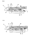
- Fig. 5 is an exploded perspective view showing a state where an arm having a plurality of hooks is coupled to a multi-adaptor for a vehicle wiper according to a second example of the present invention.
- the arm (90) having the plurality of hooks is provided with a hook (94) protruding from a free end portion (92) and an auxiliary hook (96) positioned with a distance from the hook (94), and a pair of stopper pieces (98) are formed at both side walls of the arm (90) while downwardly protruding therefrom, respectively.
- the adaptor (10') according to the second example coupled with the arm (90) having the plurality of hooks (94, 96) has the same construction as that of the adaptor of the first example, but further comprises an auxiliary hook-coupling portion (60) arranged in the main body (20) and coupled with the auxiliary hook (96) of the arm (90).
- the main body (20) of the adaptor (10') has the hook-coupling portion (30) and auxiliary hook-coupling portion (60) coupled with the hook (94) and auxiliary hook (96) of the arm (90), respectively and the support portions (40) for elastically supporting the stopper pieces (98) of the arm (90).
- the auxiliary hook-coupling portion (60) is arranged at the other end portion of the main body and hook-coupled with the auxiliary hook (96) of the arm (90).
- Such an auxiliary hook-coupling portion (60) consists of an auxiliary insertion groove (62) in which the auxiliary hook (96) of the arm (90) is inserted, and an auxiliary support projection (64) for supporting a tip of the auxiliary hook (96) inserted through the auxiliary insertion groove (62).
- the support portions (40) elastically support the stopper pieces (98) of the arm (90), and provide the arm (90) with the elastic force such that the hook (94) of the arm (90) can be supported on the support projection (34) of the hook-coupling portion (30) in close contact therewith and the auxiliary hook (96) of the arm (90) can be supported on the auxiliary support projection (64) of the auxiliary hook-coupling portion (60) in close contact therewith.
- the snap hooks (50) are additionally arranged at one end portion of the main body (20) as coupling portions coupled with the free end portion (92) of the arm (90), the arm (90) can be more firmly secured to the adaptor (10).
- the adaptor (10') according to the second example can be coupled with the arm (80) having a single hook by using the hook-coupling portion (30) and the support portions (40), the arm (80) having the single hook and arm (90) having the plurality of hooks are simultaneously compatible with the adaptor.
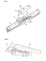
- Figs. 6 to 8 are views showing connection states where the arm having the plurality of hooks is coupled to the multi-adaptor for a vehicle wiper according to the second example of the present invention.
- a process of coupling of the arm (90) having the plurality of hooks As illustrated in Fig. 6 , the arm (90) is placed so as to cover upper portion of the adaptor (10'), and then the hook (94) of the arm (90) is inserted in the insertion groove (32) of the hook-coupling portion (30), and at the same time, as illustrated in Fig. 7 , the auxiliary hook (96) of the arm (90) is also inserted in the auxiliary insertion groove (62) of the auxiliary hook-coupling portion (60).
- the auxiliary hook(96) of the arm (90) is inserted in the auxiliary hook-coupling portion (60) and at the same time the stopper pieces (98) of the arm (90) are fittingly coupled to the support portions (40), wherein, firstly, after downwardly elastically deforming the support portions (40) by pressing the upper portion thereof, the stopper pieces (98) of the arm (90) are fitted to the support portions (40), and then, as illustrated in Fig.
- the hook (94) of the arm (90) is supported on the support projection (34) of the hook-coupling portion (30) in close contact therewith by means of the elastic force of the support portions (40), and the auxiliary hook (96) of the arm (90) is also supported on the auxiliary support projection (64) of the auxiliary hook-coupling portion (60) in close contact therewith, and at the same time the free end portion (92) of the arm (90) is also supported on the snap hooks (50) in close contact therewith.
- the hook (94), auxiliary hook (96) and stopper pieces (98) of the arm (90) are supported on the hook-coupling portion (30), auxiliary hook-coupling portion (60) and support portions (40) of the adaptor (10') in close contact therewith, respectively, and thus the one end portion and the other end portion of the arm (90) are simultaneously secured to the adaptor (10'), whereby the arm-coupling force can be drastically increased as compared to the conventional adaptor.
- Fig. 9 is a perspective view showing construction of a multi-adaptor for a vehicle wiper according to a third example of the present invention and an arm of top lock type.
- the multi-adaptor (10") for a vehicle wiper comprises a main body (20), a coupling portion arranged at one end portion of the main body (20), to which coupling portion a free end portion (102) of the arm (100) is coupled, and support portions (40) arranged at both side walls of the main body (20) to support stopper pieces (104) of the arm (100).
- the arm (100) coupled with the multi-adaptor (10") for a vehicle wiper has a protruding free end portion (102), and a pair of stopper pieces (104) are arranged at both side walls of the arm (100), respectively while downwardly protruding and extending bent inward.
- the main body (20) is in the form of case and coupled to a blade (70) for wiping surface of glass window of the vehicle.
- the multi-adaptor (10") according to the third example of the present invention comprises snap hooks (50) as coupling portions, to which the free end portion (102) of the arm (100) is coupled.
- the snap hooks (50) are arranged at one end portion of the main body (20) to elastically support the free end portion (102) of the arm (100), and provide the arm (100) with the elastic force such that the stopper pieces (104) of the arm (100) can be supported on the support portions (40) arranged at the other end portion of the main body (20) in close contact therewith.
- the snap hooks (50) are arranged at both side walls of the one end portion of the main body (20) so as to each have elasticity, and when the free end portion (102) of the arm (100) is supported on the snap hooks in close contact therewith, the hooks are elastically deformed toward a side opposite the free end portion (102) of the arm (100), and when the stopper pieces (104) of the arm (100) are supported on the support portions (40) arranged at both side walls of the other end portion of the main body (20), the elastically deformed snap hooks (50) are restored to thereby provide the arm (100) with the elastic force such that the stopper pieces (104) of the arm (100) can be supported on the support portions (40) in close contact therewith.
- the support portions (40) are arranged at the other end portion of the main body (20) and protrude from both side walls of the other end portion of the main body (20) toward the snap hooks (50), and support the stopper pieces (104) of the arm (100) such that the free end portion (102) of the arm (100) can be elastically supported on the snap hooks (50).
- stopper projections (42) by which the stopper pieces (104) of the arm (100) are kept caught.
- the stopper pieces (104) of the arm (100) protrude downwardly from both side walls of the arm (100) and each extend bent inward, if the stopper projections (42) are formed at the tips of the support portions (40) such that the stopper pieces (104) of the arm (100) can be supported on the support portions (40) and at the same time kept caught thereby, the stopper pieces (104) of the arm (100) are kept caught by the stopper projections (42) of the support portions (40), whereby the arm (100) can be firmly secured to the adaptor (10") for a vehicle wiper without being separated therefrom.
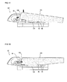
- Figs. 10 to 12 are views showing connection states where the arm of top lock type is coupled to the multi-adaptor for a vehicle wiper according to the present invention.
- a process of coupling of the arm (100) of top lock type to the multi-adaptor (100) for a vehicle wiper wherein, as illustrated in Fig. 10 , if the arm (100) is placed so as to cover the upper portion of the adaptor (10") with the stopper pieces (104) of the arm (100) abutting against the stopper projections (42) of the support portions (40), the upper portions of the snap hooks (50) are pressed by the protruding free end portion (102) of the arm (100).
- the snap hooks (50) are elastically deformed while being pressed by the free end portion (102) of the arm (100) wherein, as illustrated in Fig. 12 , if the stopper pieces (104) of the arm (100) are fitted to the stopper projections (42) of the support portions (40), the snap hooks (50) are restored from its elastic deformation to provide the elastic force such that the stopper pieces (104) of the arm (100) can be supported on the stopper projections (42) of the support portions (40) in close contact therewith, whereby the stopper pieces (104) of the arm (100) are kept caught by the stopper projections (42) of the support portions (40), thus the arm (100) is firmly secured without departing from the adaptor (10").
- the free end portion (102) and stopper pieces (104) of the arm (100) are supported on the snap hooks (50) and stopper projections (42) of the support portions (40) of the adaptor (10") in close contact therewith, respectively, and thus the one end portion and the other end portion of the arm (100) are simultaneously secured to the adaptor (10"), whereby the arm-coupling force can be drastically increased as compared to the conventional adaptor.
- the multi-adaptor for a vehicle wiper according to the third example of the present invention has wide portions coupled with the arm of top lock type by utilizing the snap hooks and support portions, thereby can drastically increase the arm-coupling force as compared to the conventional adaptor, and thus can preemptively prevent the arm from being separated from the adaptor.
Landscapes
- Engineering & Computer Science (AREA)
- Mechanical Engineering (AREA)
- Insertion Pins And Rivets (AREA)
- Pivots And Pivotal Connections (AREA)
Applications Claiming Priority (3)
| Application Number | Priority Date | Filing Date | Title |
|---|---|---|---|
| KR1020090092518A KR101038760B1 (ko) | 2009-09-29 | 2009-09-29 | 차량 와이퍼용 멀티 어댑터 |
| KR1020090092519A KR101105339B1 (ko) | 2009-09-29 | 2009-09-29 | 차량 와이퍼용 멀티 어댑터 |
| PCT/KR2010/006589 WO2011040743A2 (fr) | 2009-09-29 | 2010-09-28 | Multi-adaptateur pour essuie-glace de véhicule |
Publications (2)
| Publication Number | Publication Date |
|---|---|
| EP2484565A2 true EP2484565A2 (fr) | 2012-08-08 |
| EP2484565A4 EP2484565A4 (fr) | 2014-06-25 |
Family
ID=43826776
Family Applications (1)
| Application Number | Title | Priority Date | Filing Date |
|---|---|---|---|
| EP10820816.6A Withdrawn EP2484565A4 (fr) | 2009-09-29 | 2010-09-28 | Multi-adaptateur pour essuie-glace de véhicule |
Country Status (4)
| Country | Link |
|---|---|
| US (1) | US8959701B2 (fr) |
| EP (1) | EP2484565A4 (fr) |
| JP (1) | JP2013505879A (fr) |
| WO (1) | WO2011040743A2 (fr) |
Cited By (2)
| Publication number | Priority date | Publication date | Assignee | Title |
|---|---|---|---|---|
| CN103909907A (zh) * | 2014-04-02 | 2014-07-09 | 九江亚达实业有限公司 | 一种雨刷器多功能接头 |
| CN106515672A (zh) * | 2016-12-07 | 2017-03-22 | 丹阳市龙威汽配有限公司 | 雨刷用连接装置和应用其的雨刷及雨刷的装配方法 |
Families Citing this family (31)
| Publication number | Priority date | Publication date | Assignee | Title |
|---|---|---|---|---|
| US9457768B2 (en) | 2011-04-21 | 2016-10-04 | Pylon Manufacturing Corp. | Vortex damping wiper blade |
| US9174609B2 (en) | 2011-04-21 | 2015-11-03 | Pylon Manufacturing Corp. | Wiper blade with cover |
| DE102011079783A1 (de) * | 2011-07-26 | 2013-01-31 | Robert Bosch Gmbh | Anschlussvorrichtung zum gelenkigen Verbinden eines Wischblatts mit einem Wischarm und ein Adapter |
| CA2843527C (fr) | 2011-07-28 | 2018-11-27 | Pylon Manufacturing Corp. | Adaptateur, raccord et ensemble d'essuie-glace |
| US9108595B2 (en) | 2011-07-29 | 2015-08-18 | Pylon Manufacturing Corporation | Windshield wiper connector |
| US8806700B2 (en) * | 2011-07-29 | 2014-08-19 | Pylon Manufacturing Corporation | Wiper blade connector |
| EP2578458B1 (fr) * | 2011-10-05 | 2014-11-19 | Unipoint Electric Mfg. Co., Ltd. | Connecteur d'essuie-glace et ensemble formant connecteur d'essuie-glace |
| PL2597000T3 (pl) * | 2011-11-23 | 2014-08-29 | Unipoint Electric Mfg Co Ltd | Adapter wycieraczki szyby przedniej i zespół wycieraczki szyby przedniej |
| EP2604482A1 (fr) * | 2011-12-15 | 2013-06-19 | Unipoint Electric MFG. Co., Ltd. | Adaptateur multifonction pour essuie-glace et assemblage l'utilisant |
| MX385411B (es) | 2012-02-24 | 2025-03-18 | Pylon Mfg Corp | Escobilla limpiaparabrisas. |
| US20130219649A1 (en) | 2012-02-24 | 2013-08-29 | Pylon Manufacturing Corp. | Wiper blade |
| US10829092B2 (en) | 2012-09-24 | 2020-11-10 | Pylon Manufacturing Corp. | Wiper blade with modular mounting base |
| US9260084B2 (en) | 2013-01-03 | 2016-02-16 | Trico Products Corporation | Wiper coupler adapter and wiper assembly incorporating same |
| US9511748B2 (en) | 2013-03-15 | 2016-12-06 | Illinois Tool Works Inc. | Universal connector for attachment of a windshield wiper blade with multiple types of windshield wiper arms |
| US9555775B2 (en) | 2013-03-15 | 2017-01-31 | Illinois Tool Works Inc. | Connectors and connector kit for attachment of a windshield wiper blade to multiple types of windshield wiper arms |
| US10166951B2 (en) | 2013-03-15 | 2019-01-01 | Pylon Manufacturing Corp. | Windshield wiper connector |
| US20150013093A1 (en) * | 2013-07-12 | 2015-01-15 | Trico Products Corporation | Wiper coupler adaptor and wiper assembly incorporating same |
| USD727238S1 (en) | 2013-12-13 | 2015-04-21 | Illinois Tool Works Inc. | Cover used for windshield wiper connectors |
| US9505380B2 (en) | 2014-03-07 | 2016-11-29 | Pylon Manufacturing Corp. | Windshield wiper connector and assembly |
| CN103909906A (zh) * | 2014-04-02 | 2014-07-09 | 九江亚达实业有限公司 | 一种复合型雨刷器 |
| KR20170005815A (ko) * | 2014-05-13 | 2017-01-16 | 페더럴-모걸 모터파츠 코오포레이숀 | 자동차 앞유리 와이퍼 장치 |
| USD777079S1 (en) | 2014-10-03 | 2017-01-24 | Pylon Manufacturing Corp. | Wiper blade frame |
| US10046739B2 (en) * | 2014-12-23 | 2018-08-14 | Trico Products Corporation | Wiper adapter and wiper assembly incorporating the same |
| US10071712B2 (en) * | 2014-12-23 | 2018-09-11 | Trico Products Corporation | Wiper adapter and wiper assembly incorporating the same |
| JP6359141B1 (ja) * | 2017-03-23 | 2018-07-18 | 日本ワイパブレード株式会社 | ワイパーブレードとワイパーアームの結合構造及びワイパーブレード |
| JP6558394B2 (ja) * | 2017-04-26 | 2019-08-14 | トヨタ自動車株式会社 | SiC単結晶の製造方法及び製造装置 |
| EP3755587A4 (fr) | 2018-02-19 | 2022-06-15 | Trico Products Corporation | Adaptateur, raccord et ensemble bras d'essuie-glace de pare-brise |
| USD896156S1 (en) | 2019-04-16 | 2020-09-15 | Trico Products Corporation | Coupler for windshield wiper |
| USD904275S1 (en) | 2019-04-16 | 2020-12-08 | Trico Products Corporation | Adapter for windshield wiper arm |
| USD895523S1 (en) | 2019-04-16 | 2020-09-08 | Trico Products Corporation | Coupler for windshield wiper |
| CN113561941B (zh) * | 2020-11-30 | 2023-06-27 | 厦门富可汽车配件有限公司 | 一种适配器及雨刷 |
Family Cites Families (17)
| Publication number | Priority date | Publication date | Assignee | Title |
|---|---|---|---|---|
| US2031297A (en) * | 1931-06-05 | 1936-02-18 | John W Anderson | Windshield wiper |
| US6300429B1 (en) | 1998-12-31 | 2001-10-09 | Union Carbide Chemicals & Plastics Technology Corporation | Method of modifying near-wall temperature in a gas phase polymerization reactor |
| DE10212441A1 (de) * | 2002-03-21 | 2003-11-13 | Valeo Auto Electric Gmbh | Wischvorrichtung mit Flachwischblatt und Wischarm |
| US7891044B2 (en) * | 2002-11-26 | 2011-02-22 | Valeo Wischersysteme Gmbh | Device for detachably linking a wiper blade with a driven wiper arm |
| JP4615511B2 (ja) | 2003-05-09 | 2011-01-19 | フオルクスヴアーゲン アクチエンゲゼルシヤフト | ウインドウワイパ装置のワイパアームに設けられるワイパブレードのための接続装置 |
| FR2865699B1 (fr) * | 2004-01-30 | 2007-09-28 | Valeo Systemes Dessuyage | Connecteur pour relier un bras en troncon de profile a une structure articulee d'un balai d'essuie-glace |
| US7774892B2 (en) * | 2005-04-04 | 2010-08-17 | Trico Products Corporation | Wiper coupler and wiper assembly incorporating same |
| DE102005016486A1 (de) | 2005-04-08 | 2006-10-12 | Robert Bosch Gmbh | Vorrichtung zum gelenkigen Verbinden eines Wischblatts mit einem Wischarm eines Scheibenwischers |
| FR2890925B1 (fr) * | 2005-09-21 | 2009-12-25 | Valeo Systemes Dessuyage | Connecteur de montage et d'articulation d'un balai d'essuyage sur l'extremite d'un bras d'entrainement |
| KR100692369B1 (ko) | 2006-02-23 | 2007-03-12 | 주식회사 캄코 | 와이퍼 연결장치의 와이퍼 암 연결체 |
| EP1849666B1 (fr) | 2006-04-28 | 2011-02-23 | Federal-Mogul S.A. | Dispositif d'essuie-glace |
| DE102007022185B4 (de) | 2007-02-19 | 2018-12-13 | Robert Bosch Gmbh | Verbindungselement zum gelenkigen Verbinden eines Wischblatts mit einem Wischarm |
| JP4878565B2 (ja) * | 2007-02-28 | 2012-02-15 | 株式会社ミツバ | ワイパ装置 |
| KR20080099013A (ko) * | 2007-05-08 | 2008-11-12 | 주식회사 캐프 | 자동차 와이퍼 블레이드장치의 탑록킹 아암용 커넥터 |
| KR100961662B1 (ko) | 2008-03-21 | 2010-06-09 | 에이디엠이십일 주식회사 | 와이퍼 블레이드와 와이퍼 아암의 연결장치 |
| KR100891195B1 (ko) | 2008-04-30 | 2009-04-02 | 주식회사 캐프 | 차량용 범용 와이퍼 장치 |
| US20100205763A1 (en) * | 2009-02-18 | 2010-08-19 | Chin Pech Co., Ltd. | Universal Adaptors for Connecting Wiper Blades to Wiper Arms |
-
2010
- 2010-09-28 JP JP2012532005A patent/JP2013505879A/ja active Pending
- 2010-09-28 US US13/498,872 patent/US8959701B2/en not_active Expired - Fee Related
- 2010-09-28 WO PCT/KR2010/006589 patent/WO2011040743A2/fr not_active Ceased
- 2010-09-28 EP EP10820816.6A patent/EP2484565A4/fr not_active Withdrawn
Cited By (2)
| Publication number | Priority date | Publication date | Assignee | Title |
|---|---|---|---|---|
| CN103909907A (zh) * | 2014-04-02 | 2014-07-09 | 九江亚达实业有限公司 | 一种雨刷器多功能接头 |
| CN106515672A (zh) * | 2016-12-07 | 2017-03-22 | 丹阳市龙威汽配有限公司 | 雨刷用连接装置和应用其的雨刷及雨刷的装配方法 |
Also Published As
| Publication number | Publication date |
|---|---|
| EP2484565A4 (fr) | 2014-06-25 |
| WO2011040743A2 (fr) | 2011-04-07 |
| WO2011040743A3 (fr) | 2011-09-09 |
| JP2013505879A (ja) | 2013-02-21 |
| US20120180244A1 (en) | 2012-07-19 |
| US8959701B2 (en) | 2015-02-24 |
Similar Documents
| Publication | Publication Date | Title |
|---|---|---|
| EP2484565A2 (fr) | Multi-adaptateur pour essuie-glace de véhicule | |
| EP2635467B1 (fr) | Essuie-glace de pare-brise ayant un coupleur présentant des caractéristiques d'autoverrouillage | |
| US8935825B2 (en) | Wiper blade assembly | |
| US8327500B2 (en) | Wiper blade | |
| EP2468588B1 (fr) | Structure d'assemblage de balai d'essuie-glace | |
| US9555774B2 (en) | Windscreen wiper device | |
| EP2471693A2 (fr) | Adaptateur multiple pour un essuie-glace de véhicule | |
| CN103459211B (zh) | 刮水片适配器装置 | |
| EP2271526A1 (fr) | Balai d essuie-glace pour automobile | |
| CN104442720A (zh) | 扁平雨刮器组件及其耦合方法 | |
| CN101925495B (zh) | 用于机动车风挡擦拭器刮片的连接平台 | |
| KR101105339B1 (ko) | 차량 와이퍼용 멀티 어댑터 | |
| KR100999126B1 (ko) | 와이퍼 블레이드 조립체 | |
| CN105270342A (zh) | 用于联接雨刮片与雨刮臂的适配器设备 | |
| JP5524452B2 (ja) | 車両用ワイパー及びワイパーブレードの脱落防止ストッパー | |
| JP2019051852A (ja) | ワイパブレード | |
| KR200407928Y1 (ko) | 자동차용 와이퍼 블레이드의 결합구조 | |
| KR101038760B1 (ko) | 차량 와이퍼용 멀티 어댑터 | |
| KR100705663B1 (ko) | 와이퍼 블레이드 | |
| KR100893194B1 (ko) | 자동차 유리 세척용 블레이드 조립체 | |
| KR100974702B1 (ko) | 자동차용 와이퍼블레이드 장치 | |
| KR101074135B1 (ko) | 와이퍼 장치 | |
| JP5638917B2 (ja) | ワイパブレード | |
| KR20090093022A (ko) | 차량용 와이퍼 장치 | |
| KR20000056940A (ko) | 차량용 와이퍼 블레이드 |
Legal Events
| Date | Code | Title | Description |
|---|---|---|---|
| PUAI | Public reference made under article 153(3) epc to a published international application that has entered the european phase |
Free format text: ORIGINAL CODE: 0009012 |
|
| 17P | Request for examination filed |
Effective date: 20120326 |
|
| AK | Designated contracting states |
Kind code of ref document: A2 Designated state(s): AL AT BE BG CH CY CZ DE DK EE ES FI FR GB GR HR HU IE IS IT LI LT LU LV MC MK MT NL NO PL PT RO SE SI SK SM TR |
|
| DAX | Request for extension of the european patent (deleted) | ||
| A4 | Supplementary search report drawn up and despatched |
Effective date: 20140526 |
|
| RIC1 | Information provided on ipc code assigned before grant |
Ipc: B60S 1/32 20060101ALI20140520BHEP Ipc: B60S 1/40 20060101AFI20140520BHEP |
|
| 17Q | First examination report despatched |
Effective date: 20160405 |
|
| STAA | Information on the status of an ep patent application or granted ep patent |
Free format text: STATUS: THE APPLICATION IS DEEMED TO BE WITHDRAWN |
|
| 18D | Application deemed to be withdrawn |
Effective date: 20180404 |