EP2484865A2 - Verdichter - Google Patents
Verdichter Download PDFInfo
- Publication number
- EP2484865A2 EP2484865A2 EP12154423A EP12154423A EP2484865A2 EP 2484865 A2 EP2484865 A2 EP 2484865A2 EP 12154423 A EP12154423 A EP 12154423A EP 12154423 A EP12154423 A EP 12154423A EP 2484865 A2 EP2484865 A2 EP 2484865A2
- Authority
- EP
- European Patent Office
- Prior art keywords
- silencing
- compressor
- cylinder block
- cooling
- housing
- Prior art date
- Legal status (The legal status is an assumption and is not a legal conclusion. Google has not performed a legal analysis and makes no representation as to the accuracy of the status listed.)
- Granted
Links
Images





Classifications
-
- F—MECHANICAL ENGINEERING; LIGHTING; HEATING; WEAPONS; BLASTING
- F04—POSITIVE - DISPLACEMENT MACHINES FOR LIQUIDS; PUMPS FOR LIQUIDS OR ELASTIC FLUIDS
- F04C—ROTARY-PISTON, OR OSCILLATING-PISTON, POSITIVE-DISPLACEMENT MACHINES FOR LIQUIDS; ROTARY-PISTON, OR OSCILLATING-PISTON, POSITIVE-DISPLACEMENT PUMPS
- F04C29/00—Component parts, details or accessories of pumps or pumping installations, not provided for in groups F04C18/00 - F04C28/00
- F04C29/06—Silencing
-
- F—MECHANICAL ENGINEERING; LIGHTING; HEATING; WEAPONS; BLASTING
- F01—MACHINES OR ENGINES IN GENERAL; ENGINE PLANTS IN GENERAL; STEAM ENGINES
- F01C—ROTARY-PISTON OR OSCILLATING-PISTON MACHINES OR ENGINES
- F01C21/00—Component parts, details or accessories not provided for in groups F01C1/00 - F01C20/00
- F01C21/10—Outer members for co-operation with rotary pistons; Casings
-
- F—MECHANICAL ENGINEERING; LIGHTING; HEATING; WEAPONS; BLASTING
- F04—POSITIVE - DISPLACEMENT MACHINES FOR LIQUIDS; PUMPS FOR LIQUIDS OR ELASTIC FLUIDS
- F04B—POSITIVE-DISPLACEMENT MACHINES FOR LIQUIDS; PUMPS
- F04B39/00—Component parts, details, or accessories, of pumps or pumping systems specially adapted for elastic fluids, not otherwise provided for in, or of interest apart from, groups F04B25/00 - F04B37/00
- F04B39/0027—Pulsation and noise damping means
- F04B39/0033—Pulsation and noise damping means with encapsulations
- F04B39/0038—Pulsation and noise damping means with encapsulations of inlet or outlet channels
-
- F—MECHANICAL ENGINEERING; LIGHTING; HEATING; WEAPONS; BLASTING
- F04—POSITIVE - DISPLACEMENT MACHINES FOR LIQUIDS; PUMPS FOR LIQUIDS OR ELASTIC FLUIDS
- F04C—ROTARY-PISTON, OR OSCILLATING-PISTON, POSITIVE-DISPLACEMENT MACHINES FOR LIQUIDS; ROTARY-PISTON, OR OSCILLATING-PISTON, POSITIVE-DISPLACEMENT PUMPS
- F04C29/00—Component parts, details or accessories of pumps or pumping installations, not provided for in groups F04C18/00 - F04C28/00
- F04C29/04—Heating; Cooling; Heat insulation
-
- F—MECHANICAL ENGINEERING; LIGHTING; HEATING; WEAPONS; BLASTING
- F04—POSITIVE - DISPLACEMENT MACHINES FOR LIQUIDS; PUMPS FOR LIQUIDS OR ELASTIC FLUIDS
- F04C—ROTARY-PISTON, OR OSCILLATING-PISTON, POSITIVE-DISPLACEMENT MACHINES FOR LIQUIDS; ROTARY-PISTON, OR OSCILLATING-PISTON, POSITIVE-DISPLACEMENT PUMPS
- F04C29/00—Component parts, details or accessories of pumps or pumping installations, not provided for in groups F04C18/00 - F04C28/00
- F04C29/06—Silencing
- F04C29/065—Noise dampening volumes, e.g. muffler chambers
- F04C29/066—Noise dampening volumes, e.g. muffler chambers with means to enclose the source of noise
-
- F—MECHANICAL ENGINEERING; LIGHTING; HEATING; WEAPONS; BLASTING
- F04—POSITIVE - DISPLACEMENT MACHINES FOR LIQUIDS; PUMPS FOR LIQUIDS OR ELASTIC FLUIDS
- F04C—ROTARY-PISTON, OR OSCILLATING-PISTON, POSITIVE-DISPLACEMENT MACHINES FOR LIQUIDS; ROTARY-PISTON, OR OSCILLATING-PISTON, POSITIVE-DISPLACEMENT PUMPS
- F04C29/00—Component parts, details or accessories of pumps or pumping installations, not provided for in groups F04C18/00 - F04C28/00
- F04C29/12—Arrangements for admission or discharge of the working fluid, e.g. constructional features of the inlet or outlet
-
- F—MECHANICAL ENGINEERING; LIGHTING; HEATING; WEAPONS; BLASTING
- F04—POSITIVE - DISPLACEMENT MACHINES FOR LIQUIDS; PUMPS FOR LIQUIDS OR ELASTIC FLUIDS
- F04C—ROTARY-PISTON, OR OSCILLATING-PISTON, POSITIVE-DISPLACEMENT MACHINES FOR LIQUIDS; ROTARY-PISTON, OR OSCILLATING-PISTON, POSITIVE-DISPLACEMENT PUMPS
- F04C18/00—Rotary-piston pumps specially adapted for elastic fluids
- F04C18/08—Rotary-piston pumps specially adapted for elastic fluids of intermeshing-engagement type, i.e. with engagement of co-operating members similar to that of toothed gearing
- F04C18/12—Rotary-piston pumps specially adapted for elastic fluids of intermeshing-engagement type, i.e. with engagement of co-operating members similar to that of toothed gearing of other than internal-axis type
- F04C18/126—Rotary-piston pumps specially adapted for elastic fluids of intermeshing-engagement type, i.e. with engagement of co-operating members similar to that of toothed gearing of other than internal-axis type with radially from the rotor body extending elements, not necessarily co-operating with corresponding recesses in the other rotor, e.g. lobes, Roots type
Definitions
- the present invention relates to compressors.
- the fuel cell In order to reduce the carbon dioxide emissions, electric vehicles using a fuel cell have been developed.
- the fuel cell generates electric power by an electrochemical reaction between oxygen supplied to a cathode and hydrogen supplied to an anode.
- oxygen supplied to a cathode and hydrogen supplied to an anode In an electric vehicle, in order to supply oxygen to the cathode of the fuel cell, oxygen in air compressed and supplied by a compressor is used.
- the compressor has a problem in that various noises are generated from an air inlet side and a discharge outlet side.
- a heat exchanger such as an intercooler or the like is provided to reduce the temperature of the discharged air.
- auxiliaries are mounted in an electric vehicle, and hence there is a problem that it is difficult to secure a mounting space.
- Japanese Patent Application Laid-open No. 2003-184767 describes a screw compressor having two rotors to be mounted on a fuel cell vehicle in which there is provided a silencing and cooling device having a silencing function for reducing noise from the discharge outlet side and a function for cooling discharged fluid (air).
- a cover which internally forms an additional space is attached to the outside of the housing of a compressor, and the additional space is formed between two planes which extend orthogonal to a plane connecting the two central axes of the two rotors that are in parallel with each other, and further the two planes pass through the two individual central axes. That is, the additional space is formed at a position where a valley is formed by the pair of rotors in a part of the housing.
- the additional space forms an inlet-side space connected to a discharge port of a space where the rotors are accommodated and an exit-side space connected to a discharge outlet serving as an opening of the cover.
- the inlet-side space and the exit-side space are connected via a plurality of heat exchanging tubes provided in the additional space.
- heat exchanging flow paths are formed in the plurality of heat exchanging tubes, and cooling water paths are formed between the plurality of heat exchanging tubes.
- heat exchanging fins attached to the outside of the heat exchanging tubes protrude into the cooling water paths.
- the present invention has been achieved in order to solve such problem, and an object thereof is to provide a compressor which has a function of cooling a discharged fluid, and is capable of achieving a reduction in noise.
- a compressor according to the present invention has a housing which includes a compression mechanism for compressing and then discharging a sucked fluid and a silencing and cooling device for cooling the discharged fluid and mitigating pressure fluctuations thereof, wherein the housing has a cylinder block integrally formed so as to include a compression space which accommodates the compression mechanism, a silencing and cooling space which accommodates the silencing and cooling device, and a communicating hole which provides communication between the compression space and the silencing and cooling space.
- the compressor 101 integrally includes a compression mechanism portion 10 which internally has a compression mechanism for compressing air as a fluid, and a silencing and cooling portion 30 which internally has a water-cooled intercooler core.
- the compressor 101 includes a motor 40 which is integrally coupled to the compression mechanism portion 10 and serves as a drive device for driving the compression mechanism of the compression mechanism portion 10. That is, the compressor 101 is supplied to the market as an assembly of the compressor with the compression mechanism portion 10, the silencing and cooling portion 30, and the motor 40 provided therein.
- a z axis extends from the compression mechanism portion 10 toward the silencing and cooling portion 30, a direction from the compression mechanism portion 10 toward the silencing and cooling portion 30 is a +z direction, and a direction opposite to the +z direction is a -z direction.
- a y axis extends from the compression mechanism portion 10 toward the motor 40 perpendicularly to the z axis, a direction from the compression mechanism portion 10 toward the motor 40 is a +y direction, and a direction opposite to the +y direction is-y direction.
- an x axis extends perpendicularly to the y axis and the z axis, a direction from left to right on a paper sheet with the drawing is a +x direction, and a direction opposite to the +x direction is a -x direction.
- FIG. 2 there is shown a cross section of the compressor 101 including a line in the y-y direction and a line in the z-z direction of FIG. 1 , i.e., a view of a cross section of the compressor 101 in parallel with a plane including the y axis and the z axis as viewed from the +x direction toward the -x direction, i.e. , a view of a cross section of the compressor 101 which passes through the central axis of each of a main rotary shaft 6 of the compression mechanism portion 10 and and a drive shaft 42 of the motor 40.
- the compressor 101 has a housing 1 formed integrally with a cylinder block 3 as a central housing, a front housing 2 joined to the cylinder block 3 on a side opposite to the side of the motor 40, a rear housing 4 joined to the cylinder block 3 on the side of the motor 40, and a gear cover 5 joined to the rear housing 4 on the side of the motor 40.
- a shell 41 constituting a casing of the motor 40 is integrally coupled to the gear cover 5 on a side opposite to the side of the rear housing 4 and the shell 41 also constitutes a part of the housing 1.
- the cylinder block 3 has a structure in which a first cylinder block portion 3A forming the compression mechanism portion 10 and a second cylinder block portion 3B forming the silencing and cooling portion 30 are integrally molded by using the same metal material by casting or the like.
- the first cylinder block portion 3A internally forms a rotor chamber 3A1 having one side opened in the +y direction, while the second cylinder block portion 3B internally forms a prism-like through portion 3B1 having both sides opened in the +y direction and the -y direction.
- the rotor chamber 3A1 constitutes a compression space.
- the rear housing 4 has a structure in which a first rear housing portion 4A forming the compression mechanism portion 10 and a second rear housing portion 4B forming the silencing and cooling portion 30 are integrally molded by using the same metal material by casting or the like.
- the first rear housing portion 4A is joined to the first cylinder block portion 3A so as to cover the opened side of the rotor chamber 3A1.
- the second rear housing portion 4B forms a prism-like concave portion 4B1 having a side opened in the -y direction and fitting the through portion 3B1, and is joined to the second cylinder block portion 3B.
- the gear cover 5 forms a closed gear chamber 5A on the side of the compression mechanism portion 10 together with the first rear housing portion 4A.
- the compression mechanism portion 10 has the main rotary shaft 6 passing through the first cylinder block portion 3A and the first rear housing portion 4A and extending into the gear chamber 5A.
- the main rotary shaft 6 is coupled to the drive shaft 42 of the motor 40 via a first gear 11 so as to be rotatable integrally with the drive shaft 42.
- the main rotary shaft 6 is radially supported by a ball bearing 12 provided in the first cylinder block portion 3A and a ball bearing 13 provided in the first rear housing portion 4A.
- the compression mechanism portion 10 has a sub-rotary shaft 7 (see FIG. 3 ) passing through the first cylinder block portion 3A and the first rear housing portion 4A and extending into the gear chamber 5A.
- the sub-rotary shaft 7 is coupled to a second gear in the gear chamber 5A (not shown) so as to be rotatable integrally with the second gear, and the second gear is engaged with the first gear 11.
- the concave portion 2B1, the through portion 3B1 and the concave portion 4B1 form a silencing and cooling chamber 31 as one silencing and cooling space in a generally rectangular parallelepiped shape inside the silencing and cooling portion 30.
- the compression mechanism portion 10 has a first rotor 8 which is provided inside the rotor chamber 3A1 and coupled to the main rotary shaft 6 so as to be rotatable integrally with the main rotary shaft 6, and a second rotor 9 (see FIG. 3 ) which is provided inside the rotor chamber 3A1 and coupled to the sub-rotary shaft 7 (see FIG. 3 ) so as to be rotatable integrally with the sub-rotary shaft 7.
- the first and second rotors 8 and 9 constitute rotating bodies.
- the first and second rotors 8 and 9 are three-bladed rotors each having three protruding portions, and have the same shape.
- the first and second rotors 8 and 9 are engaged with each other such that the protruding portion of one of the rotors fits between the protruding portions of the other rotor.
- the first cylinder block portion 3A of the cylinder block 3, the first rear housing portion 4A of the rear housing 4, the gear cover 5, the first rotor 8, the second rotor 9, the main rotary shaft 6, the sub-rotary shaft 7, the first gear 11, the second gear (not shown), and members included inside them constitute the compression mechanism 10A which compresses and then discharges sucked air.
- the rotor chamber 3A1 accommodates a portion where air is compressed in the compression mechanism 10A.
- a discharge hole 3D as a communicating hole which provides communication between the rotor chamber 3A1 and the silencing and cooling chamber 31 is formed between the rotor chamber 3A1 and the through portion 3B1 (see FIG. 2 ).
- the discharge hole 3D is opened at an inlet 33 of the silencing and cooling chamber 31.
- a suction hole 3C is formed on a side opposite to the side of the discharge hole 3D relative to the rotor chamber 3A1.
- a suction pipe having an air cleaner (not shown) or the like attached thereto is connected to an outer suction opening 20 of the suction hole 3C when the compressor 101 is mounted on a vehicle.
- a side portion 3BA (see FIG. 3 ) of the second cylinder block portion 3B of the cylinder block 3 in the -x direction is formed with a discharge outlet 34 which provides communication between the silencing and cooling chamber 31 and the outside.
- the discharge outlet 34 is opened to the outside of the silencing and cooling portion 30 in an orientation different from that of the inlet 33, and communicates with a cathode of a fuel cell (not shown) via a pipe.
- a water-cooled intercooler core 32 formed of cooling pipes in which cooling water flows with fins attached to the cooling pipes.
- the fins are provided to protrude into fluid flow paths formed between the cooling pipes, and divide the fluid flow paths into lattice-like flow paths. Further, the fins increase heat transfer area between the fluid flowing in the flow paths and the cooling pipes to improve mutual heat exchange efficiency.
- the intercooler core 32 extends to divide the silencing and cooling chamber 31 into a first silencing and cooling chamber portion 31A including the inlet 33 and a second silencing and cooling chamber portion 31B including the discharge outlet 34. Consequently, air discharged from the inlet 33 into the first silencing and cooling chamber portion 31A inevitably passes through the intercooler core 32 to flow into the second silencing and cooling chamber portion 31B, and changes its direction to be discharged to the outside from the discharge outlet 34. In this arrangement, the intercooler core 32 constitutes a silencing and cooling device.
- the compressor 101 when the motor 40 is started, the motor 40 causes the drive shaft 42 to rotate, the first gear 11 and the main rotary shaft 6 integral with the drive shaft 42 are made to rotate with the rotation of the drive shaft 42 in the compression mechanism portion 10, and the first rotor 8 is made to rotate together with the main rotary shaft 6.
- the second gear (not shown) engaged with the first gear 11 is made to rotate, and the sub-rotary shaft 7 (see FIG. 3 ) and the second rotor 9 (see FIG. 3 ) are further made to rotate together with the second gear.
- a negative pressure is generated in the vicinity of the suction hole 3C in the rotor chamber 3A1 serving as the suction side, and air as outside air is sucked into the rotor chamber 3A1 from the outside of the compressor 101 via the suction hole 3C and the suction opening 20.
- the sucked air is contained in a space 3E1 surrounded by the first rotor 8 and an inner peripheral surface 3A1A of the rotor chamber 3A1, and a space 3E2 surrounded by the second rotor 9 and the inner peripheral surface 3A1A of the rotor chamber 3A1.
- the air contained in the spaces 3E1 and 3E2 is carried along the inner peripheral surface 3A1A of the rotor chamber 3A1 in the directions P and Q, and is discharged to the discharge hole 3D serving as the discharge side in a pressurized state. All of the compressed air discharged to the discharge hole 3D is discharged from the inlet 33 into the first silencing and cooling chamber portion 31A of the silencing and cooling chamber 31 after passing through the discharge hole 3D, further passes through the intercooler core 32 to be discharged into the second silencing and cooling chamber portion 31B, and is discharged to the outside of the compressor 101 from the discharge outlet 34 to be supplied to the cathode of the fuel cell (not shown) as an oxidant.
- an area of a portion where a radiant sound is generated by the discharge pulsation corresponds only to an area of the wall portion of the housing 1 surrounding the first silencing and cooling chamber portion 31A, and is therefore small so that the generated radiant sound is low. Accordingly, in the compressor 101, the noise resulting from the discharge pulsations is reduced by the two actions described above.
- the compressor 101 has the housing 1 which includes the compression mechanism 10A for compressing and then discharging the sucked air and the intercooler core 32 for cooling the discharged air and mitigating the pressure fluctuation thereof.
- the housing 1 has the cylinder block 3 which is integrally formed so as to include the rotor chamber 3A1 which accommodates the compression mechanism 10A, the silencing and cooling chamber 31 which accommodates the intercooler core 32, and the discharge hole 3D which provides communication between the rotor chamber 3A1 and the silencing and cooling chamber 31.
- the intercooler core 32 is capable of cooling the discharged air, and also reducing the noise resulting from the discharge pulsations by mitigating the pressure fluctuations of the discharged air.
- the intercooler core 32 has both the function of silencing and cooling the air, whereby it is possible to reduce the size of the structure for silencing and cooling the air.
- the silencing and cooling chamber 31 is made to communicate with the discharge side of the rotor chamber 3A1 to be included integrally in the rotor chamber 3A1, whereby the pipe between the silencing and cooling chamber 31 and the rotor chamber 3A1 is obviated making it possible to further reduce the size of the structure therefor.
- the compressor 101 allows a reduction in noise while having the function of cooling the discharged air.
- the intercooler core 32 when the intercooler core 32 is a water cooled type, the intercooler core 32 can reduce the temperature of the discharged air by causing the cooling water flowing in the cooling pipes inside the intercooler core 32 to perform heat exchange with the discharged air passing through the intercooler core 32.
- the intercooler core 32 when the intercooler core 32 is an air cooled type, the intercooler core 32 can reduce the temperature of the discharged air by causing gas flowing inside the intercooler core 32 to perform heat exchange with the discharged air passing through the intercooler core 32. Further, the intercooler core 32 improves the heat exchange efficiency of the discharged air by having the fins protrude into the flow paths in which the discharged air flows.
- the intercooler core 32 can perform the functions of silencing and cooling the discharged air, the intercooler core 32 allows a reduction in the size of the silencing and cooling chamber 31 by abolishing the use of a silencer or the like.
- the housing 1 of the compressor 101 has the shell 41 which accommodates the motor 40 for driving the compression mechanism 10A.
- the compressor 101 is supplied as an assembly of the compressor with the compression mechanism portion 10, the silencing and cooling portion 30 and the motor 40 provided therein. Therefore, it becomes possible to provide a small compressor having the drive device and the functions of silencing and cooling the discharged air.
- the first front housing portion 2A, the first cylinder block portion 3A and the first rear housing portion 4A, and the second front housing portion 2B, the second cylinder block portion 3B and the second rear housing portion 4B are integrally molded by using metal material, respectively.
- each of the front housing 2, the cylinder block 3 and the rear housing 4 is formed of one seamless continuous member. Therefore, it becomes possible to improve the rigidity and strength between the first and second front housing portions 2A and 2B, the first and second cylinder block portions 3A and 3B, and the first and second rear housing portions 4A and 4B.
- the silencing and cooling chamber 31 of the silencing and cooling portion 30 is formed of the front housing 2, the cylinder block 3 and the rear housing 4, the silencing and cooling chamber 31 is not limited thereto.
- the silencing and cooling chamber 31 may also be formed of the cylinder block 3 and the front housing 2, or the cylinder block 3 and the rear housing 4.
- a compressor 201 according to a second embodiment of the present invention has a single-piece structure in which the front housing 2, the cylinder block 3 and the rear housing 4 of the compressor 101 of the first embodiment are formed of one part.
- the first cylinder block portion 3A and the second cylinder block portion 3B in the compressor 101 of the first embodiment have substantially identical widths.
- the cylinder block 210 is obtained by integrating the front housing 2, the cylinder block 3 and the rear housing 4 in the compressor 101 of the first embodiment.
- the rotor chamber 220 internally has the main rotary shaft 6, the first rotor 8, the sub-rotary shaft 7 and the second rotor 9.
- the silencing and cooling chamber 231 is formed on the discharge side of the rotor chamber 220, and internally has the intercooler core 32.
- FIG. 5 which is a view showing a central cross section of the cylinder block 210 and the gear cover 25 including a line in the y-y direction and a line in the z-z direction of FIG. 4 as viewed from the direction V, on a front side opposite to the side of the gear cover 25, the cylinder block 210 integrally has a front wall 210F which corresponds to the front housing 2 in the compressor 101 of the first embodiment.
- the front wall 210F covers the rotor chamber 220 and the silencing and cooling chamber 231 from the front side.
- an upper wall 210A which forms the ceiling of the silencing and cooling chamber 231 so as to extend to be inclined downward from the front wall 210F toward side walls 210B and 210C and the rear wall 210E which are formed to be lower than the front wall 210F.
- the height of the cylinder block 210 is reduced, and the area of walls surrounding the silencing and cooling chamber 231 is reduced significantly as compared with a case where the side walls 210B and 210C and the rear wall 210E are formed to have the same height as that of the front wall 210F.
- the silencing and cooling chamber 231 is surrounded by the upper wall 210A, the side walls 210B and 210C, the partition wall 210G, the front wall 210F and the rear wall 210E, and is opened at the core insertion opening 210F2, the discharge outlet 234 and the inlet 233. Consequently, the silencing and cooling chamber 231 is made by forming, in the cylinder block 210, a recessed space which has the rear wall 210E as its bottom portion and extends in the horizontal direction from the front wall 210F to the rear wall 210E.
- the silencing and cooling chamber 231 is formed into the recessed shape having the rear wall 210E as the bottom portion, the silencing and cooling chamber 231 is surrounded by the rigid structure. Therefore, the silencing and cooling chamber 231 is surrounded by walls having a rigidity greater than that of the walls of the silencing and cooling chamber 31 of the first embodiment. With this arrangement, the vibration of the walls surrounding the silencing and cooling chamber 231 relative to the other portions of the cylinder block 210 and the deformation thereof resulting from the discharge pulsation of the compression mechanism 10A are further reduced, and an increase in vibration by resonance is therefore suppressed so that it becomes possible to reduce noise.
- the shell 241 of the motor 240 and the gear cover 25 including a gear mechanism for transmitting the driving force of the motor 240 to all of the rotors 8 and 9 are fixed in tandem with each other by using the bolts 241C extending through the cylinder block 210. Since the cylinder block 210, the gear cover 25 and the shell 241 are coupled and fixed together in one line by using the fastener extending therethrough such as the bolt 241C, the rigidity of each coupling portion is increased so that it is possible to reduce the relative vibration between the cylinder block 210 and the shell 241. Note that, even when the bolt 241C extends through the cylinder block 210, a similar effect can be obtained.
- the cylinder block 210 has the substantially constant width B and length L, the cylinder block 210 is not limited thereto. At least one of the width and the length of the cylinder block 210 may be reduced from the rotor chamber 220 toward the silencing and cooling chamber 231.
- the upper wall 210A of the cylinder block 210 in the compressor 201 of the second embodiment is a member made of a material having damping properties.
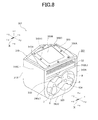
- a cylinder block 310 of the compressor 301 has an upper wall 310A" side walls 310B and 310C, a bottom wall 310D, a front wall 310F, a rotor chamber 320, a silencing and cooling chamber 331, a suction hole 310H, a discharge hole 310I and a discharge outlet 334.
- the cylinder block 310 has a rectangular opening 310A1 which provides communication between the silencing and cooling chamber 331 and the outside in the upper wall 310A.
- the cylinder block 310 does not have a rear wall in a rear end portion 310E1 but has a cooling chamber opening 310E2 which opens the silencing and cooling chamber 331 on the rear side.
- the cooling chamber opening 310E2 also serves as the core insertion opening, and the intercooler core 32 is inserted into the silencing and cooling chamber 331 from the cooling chamber opening 310E2 to be installed.
- the damping cover 350 is made from a material having damping properties.
- a material having damping properties there can be used a constrained type damping material such as a laminated damping steel sheet or a laminated pasted multilayer sheet that has a resin sandwiched between metal sheets, a non-constrained type damping material obtained by pasting, applying or spraying a resin to a metal plate, or a damping alloy in which the metal itself has a vibration absorbing ability.
- the damping alloy there can be used a composite structure-type alloy such as flake graphite cast iron or the like, a ferromagnetic-type alloy (based on inner friction) such as Silentalloy (Fe-Cr-Al) or the like, a dislocation-type alloy such as magnesium alloy or the like, and a twinning deformation-type alloy such as Mn-Cu alloy or the like.
- the material having damping properties has a loss factor ( ⁇ ) of not less than 10 -2 .
- the damping cover 350 constitutes a wall member made from the damping material in the cylinder block 310.
- the cylinder block 310 has the opening 310A1 which provides communication between the silencing and cooling chamber 331 and the outside, and the opening 310A1 is covered with the damping cover 350 made from the damping material.
- the damping cover 350 attenuates the deformation resulting from the vibration generated by the discharge pulsations of the compression mechanism 10A, and hence the damping cover 350 allows suppression of the vibration of the cylinder block 310 and a reduction in the noise of the compressor 301.
- the damping cover 350 the noise is not increased even when the rigidity of the wall of the cylinder block 310 is reduced so that the damping cover 350 allows a reduction in the weight of the compressor 301.
- the damping cover 350 is provided only on the upper wall 310A of the cylinder block 310, the damping cover 350 is not limited thereto.
- the damping cover 350 may be provided on any of the front wall 310F and the side walls 310B and 310C.
- the damping cover 350 is attached to the cylinder block 310 by using the bolts 350C, the damping cover 350 may also be embedded so as to be integrated with the cylinder block 310 at the time of molding.
- damping cover 350 may be applied to the front housing 2, the cylinder block 3 and the rear housing 4 of the first embodiment, and the upper wall 210A, the side wall 210B, the side wall 210C, the front wall 210F and the rear wall 210E of the cylinder block 210 of the second embodiment.
- a cylinder block 410 of the compressor 401 there is used a cylinder block similar in structure to the cylinder block 210 of the compressor 201 of the second embodiment.
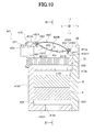
- the cylinder block 410 has an upper wall 410A, side walls 410B and 410C, a bottom wall 410D, a front wall 410F, a rear wall 410E, a rotor chamber 420, a silencing and cooling chamber 431, a suction hole 410H, a discharge hole 410I and a discharge outlet 434.
- the cylinder block 410 has a rectangular opening 410A1 which provides communication between the silencing and cooling chamber 431 and the outside in the upper wall 410A.
- the compressor 401 has a damping cover 450 which covers the opening 410AI from the outside.
- the damping cover 450 is made from a material having damping properties similar to that of the damping cover 350 of the third embodiment.
- the damping cover 450 includes a plate-like edge portion 450A which fits the outer surface of the upper wall 410A at the periphery of the opening 410A1, and a plate-like main body portion 450B which is formed integrally with the edge portion 450A inside the edge portion 450A.
- the main body portion 450B is curved so as to protrude from the inside of the silencing and cooling chamber 431 toward the outside of the cylinder block 410, and has a smooth convex shape. That is, the main body portion 450B is curved in a direction from the front wall 410F toward the rear wall 410E and also in a direction from the side wall 410B toward the side wall 410C, and has an egg shell-like shell shape.
- the compressor 401 has a partition plate 451 between the upper wall 410A and the damping cover 450.
- the partition plate 451 includes a plate-like edge portion 451A which fits the outer surface of the upper wall 410A at the periphery of the opening 410A1, and a plate-like main body portion 451B which is formed integrally with the edge portion 451A inside the edge portion 451A.
- the main body portion 451B is curved in the direction from the front wall 410F toward the rear wall 410E and also in the direction from the side wall 410B toward the side wall 410C so as to protrude from the outside of the cylinder block 410 toward the inside of the silencing and cooling chamber 431.
- the main body portion 451B has the egg shell-like shell shape.
- the partition plate 451 is formed with a plurality of through holes 451C which extend through the main body portion 451B.
- the damping cover 450 and the partition plate 451 are fixed to the upper wall 410A by using bolts 452 together with their respective edge portions 450A and 451A.
- the partition plate 451 partitions a part of the silencing and cooling chamber 431, and a hollow 453 surrounded by the damping cover 450 and the partition plate 451 is formed at position opposing an inlet 433 (the discharge hole 410I) of the silencing and cooling chamber 431.
- a thickness D in a direction from the silencing and cooling chamber 431 toward the hollow 453 along a central axis 451CC of the through hole 451C becomes smaller from the center toward end portions so that the thicknesses D at the individual through holes 451C are not identical.
- air having the pulsations discharged from the inlet 433 into the silencing and cooling chamber 431 passes through the intercooler core 32, then flows toward the partition plate 451, and flows into the hollow 453 through the through holes 451C.
- air inside the hollow 453 acts as a spring, whereby resonance (Helmholtz resonance) occurs inside the hollow 453, frictional loss at each through hole 451C is increased, and the pulsation of the air is reduced.
- the thickness D of the hollow 453 differs depending on the position of the through hole 451C, and the frequency of the reduced pulsation thereby differs. With this arrangement, in the hollow 453, the pulsation of the air is reduced in a wide frequency range.
- the damping cover 450 since the main body portion 450B of the damping cover 450 has the shell shape, the rigidity thereof is high as compared with that of the flat plate-like damping cover 350 of the third embodiment. With this arrangement, the damping cover 450 is capable of suppressing the vibration of the damping cover 450 by its high rigidity, and also suppressing the radiation of the vibration via the damping cover 450 by having material characteristics with damping properties.
- the pulsations of the air discharged into the silencing and cooling chamber 431 are reduced in the intercooler core 32 and then further reduced in the hollow 453 in the wide frequency range, and the radiation of the vibration to the outside, i.e., the radiation of sound is suppressed by the damping cover 450 having high rigidity and damping properties.
- the compressor 401 in the fourth embodiment effects similar to those of the above-described compressor 301 of the third embodiment can be obtained.
- the hollow 453, which communicates with the silencing and cooling chamber 431 via the plurality of through holes 451C and has the varied thicknesses is provided adjacent to the inner side of the damping cover 450, the vibration propagated to the damping cover 450 is reduced in the wide frequency range, the damping cover 450 in the shape having high rigidity reduces the vibration of the damping cover 450, and the radiation of sound resulting from the vibration is thereby reduced. Therefore, the compressor 401 is capable of reducing more noise than the compressor 301 of the third embodiment.
- the damping cover 450 and the partition plate 451 are only provided on the upper wall 410A of the cylinder block 410, the damping cover 450 and the partition plate 451 are not limited thereto, and they may be provided on any of the front wall 410F and the side walls 410B and 410C.
- the damping cover 450 and the partition plate 451 are attached to the cylinder block 410 by using the bolts 452, they may also be embedded so as to be integrated with the cylinder block 410 at the time of molding.
- the partition plate 451 may have a flat plate-like shape, and the damping cover 450 and/or the partition plate 451 may have a semi-cylindrical shape curved only in one direction. In this case as well, there is formed the hollow 453 having the dimensions D which are not identical at the individual through holes 451C.
- the damping cover 450 is provided on the upper wall 410A of the cylinder block 410 as a separate member, the upper wall 410A itself may be formed into the shell shape.
- the hollow 453 having the thicknesses D which are not identical at the individual through holes 451C, and the rigidity of the upper wall 410A is further improved so that the radiant sound is reduced.
- the wall thereof may be formed into the shell shape.
- the upper wall 210a can be formed into the shell shape. In this arrangement, the rigidity of the upper wall is improved so that the radiation of sound from this wall is reduced.
- either or both of the damping cover 450 and the partition plate 451 may be applied to the front housing 2, the cylinder block 3 and the rear housing 4 of the first embodiment, and the upper wall 210A, the side wall 210B, the side wall 210C, the front wall 210F and the rear wall 210E of the cylinder block 210 of the second embodiment.
- the damping cover 450 instead of the flat plate-like damping cover 350, the damping cover 450 may be used.
- the partition plate 451 may be provided in combination with the flat plate-like damping cover 350 of the third embodiment.
- a sound absorbing material 454 may be put into the whole or a part of the hollow 453 in the compressor 401 of the fourth embodiment.
- the sound absorbing material 454 may be a material which attenuates the pulsations, or a material having elasticity which generates another resonance in the hollow 453 to further reduce the pulsations in another frequency, and it is possible to thereby further reduce the pulsations in the hollow 453.
- the sound absorbing material 454 there can be used, e.g. , a porous element, an elastic element, or a foam element or the like.
- the intercooler core 32 is not limited thereto, and an air-cooled intercooler core may be provided.
- the discharge outlets 34, 234, 334 and 434 are formed in the side portion 3BA, the front wall 210F, the front wall 310F and the front wall 410F of the cylinder blocks 3, 210, 310 and 410, respectively. Consequently, when each of the compressors 101 to 401 is mounted on a vehicle such that each of the silencing and cooling chambers 31, 231, 331 and 431 is positioned on the upper side of the compressor, each of the discharge outlets 34, 234, 334 and 434 is laterally directed so that it becomes easy to mount each of the compressors 101 to 401 with each of the discharge outlets 34, 234, 334 and 434 directed in a direction other than a direction toward a passenger of the vehicle.
- the gear cover 5 or 25 is provided between the rear housing 4 and the shell 41 of the motor 40, or between the cylinder block 210, 310 or 410 and the shell 241 of the motor 240, the gear cover is not limited thereto.
- the gear cover 5 or 25 may be attached to the front housing 2 or the cylinder block 210, 310 or 410 on a side opposite to the side of the motor 40 or 240.
- each of the compressors 101 to 401 is a Roots air compressor
- the compressor is not limited thereto, and there can be used a compressor which generates discharge pulsations such as a screw compressor, a centrifugal compressor or the like.
- each of the compressors 101 to 401 is used to compress and send a fluid to the fuel cell of the fuel cell vehicle, the compressor is not limited thereto, and can also be applied to a compression mechanism of a supercharger.
Landscapes
- Engineering & Computer Science (AREA)
- Mechanical Engineering (AREA)
- General Engineering & Computer Science (AREA)
- Applications Or Details Of Rotary Compressors (AREA)
- Compressor (AREA)
- Compressors, Vaccum Pumps And Other Relevant Systems (AREA)
Applications Claiming Priority (3)
| Application Number | Priority Date | Filing Date | Title |
|---|---|---|---|
| JP2011024987 | 2011-02-08 | ||
| JP2011237182 | 2011-10-28 | ||
| JP2011273700A JP5522158B2 (ja) | 2011-02-08 | 2011-12-14 | 圧縮機 |
Publications (3)
| Publication Number | Publication Date |
|---|---|
| EP2484865A2 true EP2484865A2 (de) | 2012-08-08 |
| EP2484865A3 EP2484865A3 (de) | 2016-05-18 |
| EP2484865B1 EP2484865B1 (de) | 2018-09-12 |
Family
ID=45655438
Family Applications (1)
| Application Number | Title | Priority Date | Filing Date |
|---|---|---|---|
| EP12154423.3A Not-in-force EP2484865B1 (de) | 2011-02-08 | 2012-02-08 | Verdichter |
Country Status (4)
| Country | Link |
|---|---|
| US (1) | US9366258B2 (de) |
| EP (1) | EP2484865B1 (de) |
| JP (1) | JP5522158B2 (de) |
| CN (1) | CN102635552B (de) |
Cited By (1)
| Publication number | Priority date | Publication date | Assignee | Title |
|---|---|---|---|---|
| EP3218586A4 (de) * | 2014-11-05 | 2018-06-27 | Eaton Corporation | Aufladereinlassplatten |
Families Citing this family (13)
| Publication number | Priority date | Publication date | Assignee | Title |
|---|---|---|---|---|
| WO2015179048A2 (en) * | 2014-04-17 | 2015-11-26 | Callaway Cars, Inc. | Induction assembly and system for a supercharged internal combustion engine, and method for assembly of the same |
| US9664152B2 (en) * | 2008-01-06 | 2017-05-30 | Callaway Cars, Inc. | Induction assembly and system for a supercharged internal combustion engine, and method for assembly for the same |
| JP5895902B2 (ja) | 2013-07-16 | 2016-03-30 | 株式会社豊田自動織機 | 圧縮機 |
| JP2015045251A (ja) * | 2013-08-28 | 2015-03-12 | 株式会社神戸製鋼所 | 圧縮装置 |
| US9359914B2 (en) * | 2014-08-19 | 2016-06-07 | General Electric Company | Silencing and cooling assembly with fibrous medium |
| CN107849968B (zh) * | 2015-06-11 | 2021-03-02 | 伊顿公司 | 增压器集成谐振器 |
| EP3909813B1 (de) | 2019-01-11 | 2023-09-13 | FUJIFILM Corporation | Schalldämmelement für elektrisch angetriebene fahrzeuge |
| CN111271245A (zh) * | 2020-02-10 | 2020-06-12 | 嘉兴学院 | 活塞式空气压缩机 |
| CN113107853B (zh) * | 2021-04-16 | 2022-11-01 | 安琪酵母(宜昌)有限公司 | 一种罗茨风机的内部降温机构 |
| JP7399495B2 (ja) * | 2021-10-19 | 2023-12-18 | オリオン機械株式会社 | パッケージ型回転ポンプユニット |
| CN114278563B (zh) * | 2021-12-23 | 2024-01-19 | 上海重塑能源科技有限公司 | 一种燃料电池用氢气循环泵、氢气循环系统及其工作方法 |
| CN115355170A (zh) * | 2022-07-29 | 2022-11-18 | 迈科微真空技术(苏州)有限公司 | 一种高度集成的真空泵泵体 |
| US12503974B1 (en) * | 2024-09-13 | 2025-12-23 | Kong Performance LLC | Supercharger modifications |
Citations (1)
| Publication number | Priority date | Publication date | Assignee | Title |
|---|---|---|---|---|
| JP2003184767A (ja) | 2001-12-14 | 2003-07-03 | Nippon Soken Inc | スクリュー型コンプレッサ |
Family Cites Families (17)
| Publication number | Priority date | Publication date | Assignee | Title |
|---|---|---|---|---|
| US4061444A (en) * | 1976-07-30 | 1977-12-06 | Lennox Industries, Inc. | Compressor muffling arrangement |
| US4201523A (en) * | 1978-01-23 | 1980-05-06 | Olofsson Bjorn O E | Device for cooling and silencing of noise of a compressor or vacuum pump |
| US4264282A (en) * | 1979-01-03 | 1981-04-28 | K. C. Mosier Company | Air compressor apparatus including noise-reducing means |
| US4347042A (en) * | 1980-06-02 | 1982-08-31 | Carrier Corporation | Motor compressor unit and a method of reducing noise transmitted therefrom |
| KR920010733B1 (ko) * | 1988-06-28 | 1992-12-14 | 마쯔시다덴기산교 가부시기가이샤 | 스크로울압축기 |
| JPH0557386A (ja) | 1991-08-30 | 1993-03-09 | Kanai Hiroyuki | 自動車用アルミホイールのデイスクの製造方法 |
| JP3022179B2 (ja) * | 1994-06-30 | 2000-03-15 | 株式会社三協精機製作所 | ギアポンプ |
| US6158989A (en) * | 1997-12-15 | 2000-12-12 | Scroll Technologies | Scroll compressor with integral outer housing and fixed scroll member |
| JP2002048062A (ja) * | 2000-08-04 | 2002-02-15 | Matsushita Refrig Co Ltd | 密閉型電動圧縮機 |
| US6447264B1 (en) * | 2001-02-05 | 2002-09-10 | Ingersoll-Rand Company | Compressor system |
| JP3932175B2 (ja) | 2002-03-28 | 2007-06-20 | 本田技研工業株式会社 | 燃料電池自動車 |
| JP4206799B2 (ja) | 2003-03-31 | 2009-01-14 | 株式会社豊田自動織機 | 圧縮機 |
| US7563077B2 (en) * | 2004-09-27 | 2009-07-21 | Santa Ana Roland C | Quiet fluid pump |
| CN2878733Y (zh) * | 2005-03-22 | 2007-03-14 | 西安庆安制冷设备股份有限公司 | 一种机体外设气体消声冷却器的封闭式压缩机 |
| JP4640190B2 (ja) * | 2006-01-20 | 2011-03-02 | 株式会社豊田自動織機 | 水素循環用電動ポンプ |
| JP2007247630A (ja) | 2006-03-20 | 2007-09-27 | Toyota Motor Corp | 燃料電池用気体圧縮モジュール |
| JP5895902B2 (ja) * | 2013-07-16 | 2016-03-30 | 株式会社豊田自動織機 | 圧縮機 |
-
2011
- 2011-12-14 JP JP2011273700A patent/JP5522158B2/ja not_active Expired - Fee Related
-
2012
- 2012-02-06 US US13/366,563 patent/US9366258B2/en active Active
- 2012-02-06 CN CN201210025434.8A patent/CN102635552B/zh not_active Expired - Fee Related
- 2012-02-08 EP EP12154423.3A patent/EP2484865B1/de not_active Not-in-force
Patent Citations (1)
| Publication number | Priority date | Publication date | Assignee | Title |
|---|---|---|---|---|
| JP2003184767A (ja) | 2001-12-14 | 2003-07-03 | Nippon Soken Inc | スクリュー型コンプレッサ |
Cited By (1)
| Publication number | Priority date | Publication date | Assignee | Title |
|---|---|---|---|---|
| EP3218586A4 (de) * | 2014-11-05 | 2018-06-27 | Eaton Corporation | Aufladereinlassplatten |
Also Published As
| Publication number | Publication date |
|---|---|
| CN102635552A (zh) | 2012-08-15 |
| CN102635552B (zh) | 2015-05-06 |
| US9366258B2 (en) | 2016-06-14 |
| JP5522158B2 (ja) | 2014-06-18 |
| EP2484865B1 (de) | 2018-09-12 |
| US20120201709A1 (en) | 2012-08-09 |
| EP2484865A3 (de) | 2016-05-18 |
| JP2013108488A (ja) | 2013-06-06 |
Similar Documents
| Publication | Publication Date | Title |
|---|---|---|
| EP2484865B1 (de) | Verdichter | |
| CN108915997B (zh) | 消声器、压缩机组件及冰箱 | |
| US10941776B2 (en) | Screw compressor resonator arrays | |
| CN116591962B (zh) | 螺杆压缩机 | |
| CN112324642A (zh) | 一种气缸座及具有其的压缩机 | |
| CN211288018U (zh) | 消音器、压缩机及制冷设备 | |
| CN116499106A (zh) | 消声风道及系统 | |
| CN113898554B (zh) | 压缩机结构和制冷设备 | |
| US20070217939A1 (en) | Gas-compression module for a fuel cell | |
| CN116044769B (zh) | 排气消声结构和压缩机 | |
| JP5895902B2 (ja) | 圧縮機 | |
| CN113898558A (zh) | 消音器、压缩机和制冷设备 | |
| EP2476906B1 (de) | Luftkompressor | |
| CN220869590U (zh) | 一种内排气消音组件、压缩机、电器设备 | |
| CN114017344B (zh) | 一种旋转式压缩机及制冷设备 | |
| CN118669299A (zh) | 压力脉动衰减装置、压缩机和车辆 | |
| CN212227311U (zh) | 蒸汽管组件和空调器 | |
| CN116838571A (zh) | 电动压缩机、空调系统和车辆 | |
| CN116838570A (zh) | 电动压缩机、空调系统和车辆 | |
| CN221033131U (zh) | 压缩机 | |
| KR101417098B1 (ko) | 연료전지 시스템용 공기블로워 | |
| CN216769740U (zh) | 一种室内空调器 | |
| CN117307489B (zh) | 电动压缩机、空调系统及车辆 | |
| CN215860696U (zh) | 隔板组件、压缩机及制冷制热设备 | |
| CN224017406U (zh) | 涡旋压缩机 |
Legal Events
| Date | Code | Title | Description |
|---|---|---|---|
| PUAI | Public reference made under article 153(3) epc to a published international application that has entered the european phase |
Free format text: ORIGINAL CODE: 0009012 |
|
| 17P | Request for examination filed |
Effective date: 20120208 |
|
| AK | Designated contracting states |
Kind code of ref document: A2 Designated state(s): AL AT BE BG CH CY CZ DE DK EE ES FI FR GB GR HR HU IE IS IT LI LT LU LV MC MK MT NL NO PL PT RO RS SE SI SK SM TR |
|
| AX | Request for extension of the european patent |
Extension state: BA ME |
|
| PUAL | Search report despatched |
Free format text: ORIGINAL CODE: 0009013 |
|
| AK | Designated contracting states |
Kind code of ref document: A3 Designated state(s): AL AT BE BG CH CY CZ DE DK EE ES FI FR GB GR HR HU IE IS IT LI LT LU LV MC MK MT NL NO PL PT RO RS SE SI SK SM TR |
|
| AX | Request for extension of the european patent |
Extension state: BA ME |
|
| RIC1 | Information provided on ipc code assigned before grant |
Ipc: F04C 29/06 20060101ALI20160411BHEP Ipc: F04C 18/12 20060101ALI20160411BHEP Ipc: F04C 29/12 20060101ALI20160411BHEP Ipc: F04C 29/04 20060101ALI20160411BHEP Ipc: F01C 21/10 20060101AFI20160411BHEP Ipc: F04B 39/00 20060101ALI20160411BHEP |
|
| GRAP | Despatch of communication of intention to grant a patent |
Free format text: ORIGINAL CODE: EPIDOSNIGR1 |
|
| STAA | Information on the status of an ep patent application or granted ep patent |
Free format text: STATUS: GRANT OF PATENT IS INTENDED |
|
| RIC1 | Information provided on ipc code assigned before grant |
Ipc: F04C 29/04 20060101ALI20180418BHEP Ipc: F04B 39/00 20060101ALI20180418BHEP Ipc: F04C 18/12 20060101ALI20180418BHEP Ipc: F04C 29/06 20060101ALI20180418BHEP Ipc: F01C 21/10 20060101AFI20180418BHEP Ipc: F04C 29/12 20060101ALI20180418BHEP |
|
| INTG | Intention to grant announced |
Effective date: 20180522 |
|
| GRAS | Grant fee paid |
Free format text: ORIGINAL CODE: EPIDOSNIGR3 |
|
| GRAA | (expected) grant |
Free format text: ORIGINAL CODE: 0009210 |
|
| STAA | Information on the status of an ep patent application or granted ep patent |
Free format text: STATUS: THE PATENT HAS BEEN GRANTED |
|
| AK | Designated contracting states |
Kind code of ref document: B1 Designated state(s): AL AT BE BG CH CY CZ DE DK EE ES FI FR GB GR HR HU IE IS IT LI LT LU LV MC MK MT NL NO PL PT RO RS SE SI SK SM TR |
|
| REG | Reference to a national code |
Ref country code: GB Ref legal event code: FG4D |
|
| REG | Reference to a national code |
Ref country code: CH Ref legal event code: EP |
|
| REG | Reference to a national code |
Ref country code: IE Ref legal event code: FG4D |
|
| REG | Reference to a national code |
Ref country code: DE Ref legal event code: R096 Ref document number: 602012050880 Country of ref document: DE |
|
| REG | Reference to a national code |
Ref country code: AT Ref legal event code: REF Ref document number: 1040821 Country of ref document: AT Kind code of ref document: T Effective date: 20181015 |
|
| REG | Reference to a national code |
Ref country code: NL Ref legal event code: MP Effective date: 20180912 |
|
| REG | Reference to a national code |
Ref country code: LT Ref legal event code: MG4D |
|
| PG25 | Lapsed in a contracting state [announced via postgrant information from national office to epo] |
Ref country code: NO Free format text: LAPSE BECAUSE OF FAILURE TO SUBMIT A TRANSLATION OF THE DESCRIPTION OR TO PAY THE FEE WITHIN THE PRESCRIBED TIME-LIMIT Effective date: 20181212 Ref country code: GR Free format text: LAPSE BECAUSE OF FAILURE TO SUBMIT A TRANSLATION OF THE DESCRIPTION OR TO PAY THE FEE WITHIN THE PRESCRIBED TIME-LIMIT Effective date: 20181213 Ref country code: SE Free format text: LAPSE BECAUSE OF FAILURE TO SUBMIT A TRANSLATION OF THE DESCRIPTION OR TO PAY THE FEE WITHIN THE PRESCRIBED TIME-LIMIT Effective date: 20180912 Ref country code: RS Free format text: LAPSE BECAUSE OF FAILURE TO SUBMIT A TRANSLATION OF THE DESCRIPTION OR TO PAY THE FEE WITHIN THE PRESCRIBED TIME-LIMIT Effective date: 20180912 Ref country code: FI Free format text: LAPSE BECAUSE OF FAILURE TO SUBMIT A TRANSLATION OF THE DESCRIPTION OR TO PAY THE FEE WITHIN THE PRESCRIBED TIME-LIMIT Effective date: 20180912 Ref country code: LT Free format text: LAPSE BECAUSE OF FAILURE TO SUBMIT A TRANSLATION OF THE DESCRIPTION OR TO PAY THE FEE WITHIN THE PRESCRIBED TIME-LIMIT Effective date: 20180912 Ref country code: BG Free format text: LAPSE BECAUSE OF FAILURE TO SUBMIT A TRANSLATION OF THE DESCRIPTION OR TO PAY THE FEE WITHIN THE PRESCRIBED TIME-LIMIT Effective date: 20181212 |
|
| PG25 | Lapsed in a contracting state [announced via postgrant information from national office to epo] |
Ref country code: AL Free format text: LAPSE BECAUSE OF FAILURE TO SUBMIT A TRANSLATION OF THE DESCRIPTION OR TO PAY THE FEE WITHIN THE PRESCRIBED TIME-LIMIT Effective date: 20180912 Ref country code: HR Free format text: LAPSE BECAUSE OF FAILURE TO SUBMIT A TRANSLATION OF THE DESCRIPTION OR TO PAY THE FEE WITHIN THE PRESCRIBED TIME-LIMIT Effective date: 20180912 Ref country code: LV Free format text: LAPSE BECAUSE OF FAILURE TO SUBMIT A TRANSLATION OF THE DESCRIPTION OR TO PAY THE FEE WITHIN THE PRESCRIBED TIME-LIMIT Effective date: 20180912 |
|
| REG | Reference to a national code |
Ref country code: AT Ref legal event code: MK05 Ref document number: 1040821 Country of ref document: AT Kind code of ref document: T Effective date: 20180912 |
|
| PG25 | Lapsed in a contracting state [announced via postgrant information from national office to epo] |
Ref country code: EE Free format text: LAPSE BECAUSE OF FAILURE TO SUBMIT A TRANSLATION OF THE DESCRIPTION OR TO PAY THE FEE WITHIN THE PRESCRIBED TIME-LIMIT Effective date: 20180912 Ref country code: NL Free format text: LAPSE BECAUSE OF FAILURE TO SUBMIT A TRANSLATION OF THE DESCRIPTION OR TO PAY THE FEE WITHIN THE PRESCRIBED TIME-LIMIT Effective date: 20180912 Ref country code: CZ Free format text: LAPSE BECAUSE OF FAILURE TO SUBMIT A TRANSLATION OF THE DESCRIPTION OR TO PAY THE FEE WITHIN THE PRESCRIBED TIME-LIMIT Effective date: 20180912 Ref country code: RO Free format text: LAPSE BECAUSE OF FAILURE TO SUBMIT A TRANSLATION OF THE DESCRIPTION OR TO PAY THE FEE WITHIN THE PRESCRIBED TIME-LIMIT Effective date: 20180912 Ref country code: PL Free format text: LAPSE BECAUSE OF FAILURE TO SUBMIT A TRANSLATION OF THE DESCRIPTION OR TO PAY THE FEE WITHIN THE PRESCRIBED TIME-LIMIT Effective date: 20180912 Ref country code: ES Free format text: LAPSE BECAUSE OF FAILURE TO SUBMIT A TRANSLATION OF THE DESCRIPTION OR TO PAY THE FEE WITHIN THE PRESCRIBED TIME-LIMIT Effective date: 20180912 Ref country code: IS Free format text: LAPSE BECAUSE OF FAILURE TO SUBMIT A TRANSLATION OF THE DESCRIPTION OR TO PAY THE FEE WITHIN THE PRESCRIBED TIME-LIMIT Effective date: 20190112 Ref country code: AT Free format text: LAPSE BECAUSE OF FAILURE TO SUBMIT A TRANSLATION OF THE DESCRIPTION OR TO PAY THE FEE WITHIN THE PRESCRIBED TIME-LIMIT Effective date: 20180912 Ref country code: IT Free format text: LAPSE BECAUSE OF FAILURE TO SUBMIT A TRANSLATION OF THE DESCRIPTION OR TO PAY THE FEE WITHIN THE PRESCRIBED TIME-LIMIT Effective date: 20180912 |
|
| PG25 | Lapsed in a contracting state [announced via postgrant information from national office to epo] |
Ref country code: SK Free format text: LAPSE BECAUSE OF FAILURE TO SUBMIT A TRANSLATION OF THE DESCRIPTION OR TO PAY THE FEE WITHIN THE PRESCRIBED TIME-LIMIT Effective date: 20180912 Ref country code: SM Free format text: LAPSE BECAUSE OF FAILURE TO SUBMIT A TRANSLATION OF THE DESCRIPTION OR TO PAY THE FEE WITHIN THE PRESCRIBED TIME-LIMIT Effective date: 20180912 Ref country code: PT Free format text: LAPSE BECAUSE OF FAILURE TO SUBMIT A TRANSLATION OF THE DESCRIPTION OR TO PAY THE FEE WITHIN THE PRESCRIBED TIME-LIMIT Effective date: 20190112 |
|
| REG | Reference to a national code |
Ref country code: DE Ref legal event code: R097 Ref document number: 602012050880 Country of ref document: DE |
|
| PLBE | No opposition filed within time limit |
Free format text: ORIGINAL CODE: 0009261 |
|
| STAA | Information on the status of an ep patent application or granted ep patent |
Free format text: STATUS: NO OPPOSITION FILED WITHIN TIME LIMIT |
|
| PG25 | Lapsed in a contracting state [announced via postgrant information from national office to epo] |
Ref country code: DK Free format text: LAPSE BECAUSE OF FAILURE TO SUBMIT A TRANSLATION OF THE DESCRIPTION OR TO PAY THE FEE WITHIN THE PRESCRIBED TIME-LIMIT Effective date: 20180912 |
|
| 26N | No opposition filed |
Effective date: 20190613 |
|
| PG25 | Lapsed in a contracting state [announced via postgrant information from national office to epo] |
Ref country code: SI Free format text: LAPSE BECAUSE OF FAILURE TO SUBMIT A TRANSLATION OF THE DESCRIPTION OR TO PAY THE FEE WITHIN THE PRESCRIBED TIME-LIMIT Effective date: 20180912 |
|
| REG | Reference to a national code |
Ref country code: CH Ref legal event code: PL |
|
| GBPC | Gb: european patent ceased through non-payment of renewal fee |
Effective date: 20190208 |
|
| PG25 | Lapsed in a contracting state [announced via postgrant information from national office to epo] |
Ref country code: LU Free format text: LAPSE BECAUSE OF NON-PAYMENT OF DUE FEES Effective date: 20190208 Ref country code: MC Free format text: LAPSE BECAUSE OF FAILURE TO SUBMIT A TRANSLATION OF THE DESCRIPTION OR TO PAY THE FEE WITHIN THE PRESCRIBED TIME-LIMIT Effective date: 20180912 |
|
| REG | Reference to a national code |
Ref country code: BE Ref legal event code: MM Effective date: 20190228 |
|
| REG | Reference to a national code |
Ref country code: IE Ref legal event code: MM4A |
|
| PG25 | Lapsed in a contracting state [announced via postgrant information from national office to epo] |
Ref country code: LI Free format text: LAPSE BECAUSE OF NON-PAYMENT OF DUE FEES Effective date: 20190228 Ref country code: CH Free format text: LAPSE BECAUSE OF NON-PAYMENT OF DUE FEES Effective date: 20190228 |
|
| PG25 | Lapsed in a contracting state [announced via postgrant information from national office to epo] |
Ref country code: GB Free format text: LAPSE BECAUSE OF NON-PAYMENT OF DUE FEES Effective date: 20190208 Ref country code: IE Free format text: LAPSE BECAUSE OF NON-PAYMENT OF DUE FEES Effective date: 20190208 |
|
| PG25 | Lapsed in a contracting state [announced via postgrant information from national office to epo] |
Ref country code: FR Free format text: LAPSE BECAUSE OF NON-PAYMENT OF DUE FEES Effective date: 20190228 Ref country code: BE Free format text: LAPSE BECAUSE OF NON-PAYMENT OF DUE FEES Effective date: 20190228 |
|
| PG25 | Lapsed in a contracting state [announced via postgrant information from national office to epo] |
Ref country code: TR Free format text: LAPSE BECAUSE OF FAILURE TO SUBMIT A TRANSLATION OF THE DESCRIPTION OR TO PAY THE FEE WITHIN THE PRESCRIBED TIME-LIMIT Effective date: 20180912 |
|
| PG25 | Lapsed in a contracting state [announced via postgrant information from national office to epo] |
Ref country code: MT Free format text: LAPSE BECAUSE OF NON-PAYMENT OF DUE FEES Effective date: 20190208 |
|
| PG25 | Lapsed in a contracting state [announced via postgrant information from national office to epo] |
Ref country code: CY Free format text: LAPSE BECAUSE OF FAILURE TO SUBMIT A TRANSLATION OF THE DESCRIPTION OR TO PAY THE FEE WITHIN THE PRESCRIBED TIME-LIMIT Effective date: 20180912 |
|
| PG25 | Lapsed in a contracting state [announced via postgrant information from national office to epo] |
Ref country code: HU Free format text: LAPSE BECAUSE OF FAILURE TO SUBMIT A TRANSLATION OF THE DESCRIPTION OR TO PAY THE FEE WITHIN THE PRESCRIBED TIME-LIMIT; INVALID AB INITIO Effective date: 20120208 |
|
| PG25 | Lapsed in a contracting state [announced via postgrant information from national office to epo] |
Ref country code: MK Free format text: LAPSE BECAUSE OF FAILURE TO SUBMIT A TRANSLATION OF THE DESCRIPTION OR TO PAY THE FEE WITHIN THE PRESCRIBED TIME-LIMIT Effective date: 20180912 |
|
| P01 | Opt-out of the competence of the unified patent court (upc) registered |
Effective date: 20230519 |
|
| PGFP | Annual fee paid to national office [announced via postgrant information from national office to epo] |
Ref country code: DE Payment date: 20231228 Year of fee payment: 13 |
|
| REG | Reference to a national code |
Ref country code: DE Ref legal event code: R119 Ref document number: 602012050880 Country of ref document: DE |
|
| PG25 | Lapsed in a contracting state [announced via postgrant information from national office to epo] |
Ref country code: DE Free format text: LAPSE BECAUSE OF NON-PAYMENT OF DUE FEES Effective date: 20250902 |